1
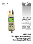
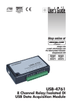
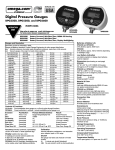
User’s Guide
Shop online at
omega.com
e-mail: [email protected]
For latest product manuals:
omegamanual.info
MADE IN TAIWAN
HHB400
Wireless Video Inspection System
OMEGAnet ® On-Line Service
omega.com
Internet e-mail
[email protected]
Servicing North America:
U.S.A.: ISO 9001 Certified
OMEGA Engineering, Inc.,
One Omega Drive, P.O. Box 4047
Stamford, CT 06907-0047
Toll-Free: 1-800-826-6342 Tel: (203) 359-1660
FAX: (203) 359-7700 e-mail: [email protected]
Canada:
976 Bergar
Laval (Quebec), H7L 5A1 Canada
Toll-Free: 1-800-826-6342 TEL: (514) 856-6928
FAX: (514) 856-6886 e-mail: [email protected]
For immediate technical or application assistance:
U.S.A. and Canada:
Sales Service: 1-800-826-6342/1-800-TC-OMEGA®
Customer Service: 1-800-622-2378/1-800-622-BEST ®
Engineering Service: 1-800-872-9436/1-800-USA-WHEN®
Mexico/Latin America:
En Español: 001 (203) 359-7803
FAX: 001 (203) 359-7807
[email protected]
e-mail: [email protected]
Servicing Europe:
Benelux:
Managed by the United Kingdom Office
Toll-Free: 0800 099 3344 TEL: +31 20 347 21 21
FAX: +31 20 643 46 4
e-mail: [email protected]
Czech Republic:
Frystatska 184
733 01 Karviná, Czech Republic
Toll-Free: 0800-1-66342
TEL: +420-59-6311899
FAX: +420-59-6311114
e-mail: [email protected]
France:
Managed by the United Kingdom Office
Toll-Free: 0800 466 342
TEL: +33 (0) 161 37 29 00
FAX: +33 (0) 130 57 54 27 e-mail: [email protected]
Germany/Austria:
Daimlerstrasse 26
D-75392 Deckenpfronn, Germany
Toll-Free: 0800 6397678
TEL: +49 (0) 7056 9398-0
FAX: +49 (0) 7056 9398-29 e-mail: [email protected]
United Kingdom:
ISO 9001 Certified
OMEGA Engineering Ltd.
One Omega Drive
River Bend Technology Centre
Northbank
Irlam, Manchester M44 5BD
United Kingdom
Toll-Free: 0800-488-488
TEL: +44 (0) 161 777-6611
FAX: +44 (0) 161 777-6622
e-mail: [email protected]
It is the policy of OMEGA Engineering, Inc. to comply with all worldwide safety and EMC/EMI regulations that apply. OMEGA
is constantly pursuing certification of its products to the European New Approach Directives. OMEGA will add the CE mark
to every appropriate device upon certification.
The information contained in this document is believed to be correct, but OMEGA accepts no liability for any errors it
contains, and reserves the right to alter specifications without notice.
WARNING: These products are not designed for use in, and should not be used for, human applications.
CONTENTS
Welcome . . . . . . . . . . . . . . . . . . . . . . . . . . . . . . . . . . . . . . . 1
Overview. . . . . . . . . . . . . . . . . . . . . . . . . . . . . . . . . . . . . . . 1
Features . . . . . . . . . . . . . . . . . . . . . . . . . . . . . . . . . . . . . . . 2
Safety Instructions . . . . . . . . . . . . . . . . . . . . . . . . . . . . 2, 3
Battery Precautions. . . . . . . . . . . . . . . . . . . . . . . . . . . . . . 3
Product Components . . . . . . . . . . . . . . . . . . . . . . . . . . . . 4
Tool Components . . . . . . . . . . . . . . . . . . . . . . . . . . . . . . 5
Monitor . . . . . . . . . . . . . . . . . . . . . . . . . . . . . . . . . . . . . . 5
Description for Keys . . . . . . . . . . . . . . . . . . . . . . . . . . . . 6
Operation Instructions. . . . . . . . . . . . . . . . . . . . . . . . . . . . 6
Connecting the Display Unit to the Camera . . . . . . . . . 7
Head and Probe . . . . . . . . . . . . . . . . . . . . . . . . . . . . 7
Accessories Installation . . . . . . . . . . . . . . . . . . . . . . 7
Connect the Grip Handle to the Monitor . . . . . . . . . 7
Install Micro SD Card . . . . . . . . . . . . . . . . . . . . . . . . 8
U-disk Function- attache to computer . . . . . . . . . . . 8
Video Output . . . . . . . . . . . . . . . . . . . . . . . . . . . . . . . 8
How to Work. . . . . . . . . . . . . . . . . . . . . . . . . . . . . . . . . . . . 8
How to operate the grip . . . . . . . . . . . . . . . . . . . . . . . 8
How to view the screen. . . . . . . . . . . . . . . . . . . . . . . . 9
How to set the screen Menu. . . . . . . . . . . . . . . . . . . . 9
Description for Keys . . . . . . . . . . . . . . . . . . . . . . 10, 11
Operation Precautions . . . . . . . . . . . . . . . . . . . . . . . . 11, 12
Trouble Shooting . . . . . . . . . . . . . . . . . . . . . . . . . . . . . . . 13
FCC Information . . . . . . . . . . . . . . . . . . . . . . . . . . . . . . . 14
Cautions . . . . . . . . . . . . . . . . . . . . . . . . . . . . . . . . . . . . . . 14
Specifications . . . . . . . . . . . . . . . . . . . . . . . . . . . . . . 15, 16
i
WELCOME
Thank you for purchasing a HHB400 Wireless Data logging
Video Inspection Camera Scope. Please read this User’s Manual
carefully before using this product.
The product is designed as a remote inspection device. It can be
used to look into tight or inaccessible areas and wirelessly transmit real time video or still images for monitoring or recording.
Typical applications may include HVAC inspection, automotive
inspection, cable routing, automotive/boat/aircraft inspection,
etc.
OVERVIEW
The HHB400 Wireless Video Inspection System
HHB400 Camera Scope with removable display comes with,
12mm Diameter, 3.28 ft. (1m) Obedient Probe, 2GB Micro SD card,
3 Extension Tools: (Mirror, Magnet, Pick-Up Hook), USB and Video
interconnect Cables, Li-ion rechargeable batteries with Charger,
Hard Blow Mold Case and Instruction Manual. It is suitable for
HVAC/R, plumbing and general inspection
The system has a high clarity color LCD of 3.5" in size. The camera
head and adjustable LED lights are imbedded in the probe tip.
Three accessories can be attached to the probe tip for various
applications: the magnetic tip is used to pick up small metal
objects; the mirror tip is used to view 90° angle; the hook is used
to grab onto objects.
HHB400 Series’ wireless function allows user to detach the LCD
from the handle and view findings remotely up to 32 ft away. The
system operates on a built-in rechargeable lithium polymer battery.
It interfaces with external displays such as computer, TV and LCD
panel via USB, SD card and AV cable.
1
FEATURES
• 12mm diameter probe, 3.28 ft. (1m) long, flexible obedient and
waterproof to IP67 standards
• Optional probe extensions are available to extend probe length up
to 16 ft. (5m)
• 3.5 in. (88.9mm) (Screen Diagonal) TFT-LCD Wireless Color Monitor can be detached from the unit for remote viewing up to 32 ft.
(10m) away
• Both monitor and handle use Li-ion rechargeable batteries.
System comes complete with batteries and charger.
• Two LED lights inside the tip of the probe illuminate dark spaces
for clear inspection
• Built-in magnets on back of monitor facilitate hands-free operation
• View results in real time or data log and record in still photo
(JPEG) or (AVI) video
• NTSC or PAL compatible USB and AV Out interfaces
• Three languages menu includes English, Spanish and French
• (x3.2) zoom feature
• 180° image rotation feature on still images
SAFETY INSTRUCTIONS
Failure to follow the instructions listed below may result in electric
shock or personal injury.
• Read and understand all instructions prior to any operation.
• Do not remove any labels from the product.
• Work in a well lit area as dark areas may cause accidents.
• Do not operate the product in the presence of flammable/
explosive gases.
• Do not use the product around corrosive chemicals which can
damage sensitive tips.
• Keep bystanders, children and visitors away while operating the
product.
2
• Stay alert, watch what you are doing and use common sense. A
moment of interruption can result in serious personal injury.
• Do not over-reach. Keep proper footing and balance at all times.
• Always wear eye protective gear. Dust mask, non-skid safety
shoes, hard hat or hearing protection must be used for appropriate conditions.
• Do not place the product on any unstable cart or surface. The
product may fall causing serious injury to a person or serious
damage to the product.
• Never spill liquid of any kind on the video display units. Liquid increases the risk of electrical shock and damage to the product.
• Do not use the device for personal or medical use.
• The units are not shock-resistant. Do not drop it.
BATTERY PRECAUTIONS
• Please use the enclosed factory power adapter, otherwise you
may damage the instrument.
• Completely exhaust the power for the first time. We recommend
full charging and full discharging for the first few times. The
charging time should not be less than 12 hours for the first few
usages. A fully activated battery will offer maximum capacity of
the built-in batteries.
• The charging and discharging time differs based on the current
consumption of the units’ components.
• Always keep the charging connector away from the metal and
oily objects.
• Fully charge the battery to make sure it has high performance.
• Don’t compress and puncture the battery inside.
• “Li-ion” Rechargeable battery inside! Please do not open battery
compartment in the handle unless battery replacement is necessary.
• Don’t throw the product into fire, this may cause an explosion.
• Dispose the battery properly. High temperature will cause the
battery to explode. Some countries have regulations concerning
battery disposal.
Please follow all applicable regulations.
3
PRODUCT COMPONENTS
Fig. 1
Fig. 3
10
11
Fig. 4
1.Camera head and Probe
2.The grip
3.LCD Screen
4.Magnetic tip
5.Hook tip
6.Mirror tip
7.DC adapter
8.One-into-two cable
9.Micro SD memory card
10.TV cable
11.USB cable
4
TOOL COMPONENTS
Grip Handle
A.Camera protection cover
(Remove cover before use)
B.Camera head
C.Probe
D.Probe connector
E.Power indicator——Green
lights means normal power;
Red light means low battery.
F.Switch / Wheel button to
adjust the LED brightness
G.Charging light indicator
H.Charging interface
Fig. 5
Monitor
I.
J.Locking buckle clip
K.Signal connector slot
L.Charging light indicator
M.Charging interface
N.Micro SD socket
O.USB interface
Fig. 6
P.Video Out
Q.
R.
S.MENU
T.
U.
5
V.LCD screen
W.Base stand
DESCRIPTION FOR KEYS
Keys
View mode
Switch into playback
mode; Hold for 3s to
turn off the unit.
Playback mode
Switch into view
mode; Hold for 3s
to turn off the unit.
Menu set
Hold for 3s to turn
off the unit.
MENU
Switch into menu set.
Switch into current
file operation, delete
single all format the
memory card, etc.
Set functions set
date and time
XXXX
Take a photo
Show the last photo
or video;
Moving to left;
XXXX
Take a video
Show the next photo
or video;
Moving to right
XXXX
Image rotation
Play pause, resume
the video file;
Moving up / progressive increase
data and time;
XXXX
Image magnify
Stop video file;
View six files or six
folders.
Moving down /
progressive
decrease data
and time;
OPERATION INSTRUCTIONS
• Battery Charging
1. Connect the DC cable to the grip and/or screen.
2. Plug the AC plugs to household power outlet.
3. The LED G and/or L turns red means charging.
4. The LED G and/or L turns green, means fully charged
5. Pull out the AC plug of adapter.
Notes: If you want to charge both the grip and screen, use the oneto-two cable. The single end goes to the adapter, and the
double end goes to screen and grip.
6
CONNECTING THE DISPLAY UNIT
TO THE CAMERA
HEAD AND PROBE:
The display unit must be connected to
the camera head and probe. To connect
the probe to the display unit, make sure
the keyed ends are properly aligned
(See Fig. 7). Once they are aligned,
tighten the nut.
ACCESSORIES INSTALLATION:
The three accessories include mirror tip,
hook tip and magnetic tip (See Fig. 2). All
are attached to the camera head the same
way. Hold the camera head as shown in
Fig. 8, slip the semicircle end of the
accessory over the flats of the camera
head then rotate the accessory 90° to
fix it in place as shown in Fig. 9.
• Connect the grip handle to Monitor
The product can work with the grip detached
from screen and the grip attached with
screen; Slide the slot at the back screen into
the slot of grip in the left direction until you
hear the locking sound, which means connection is accomplished. Press the lock
buckle clip and slide to the right direction to
detach the screen (FIG.10).
Note: The wireless function is off while the
product is attached to the screen on the grip, which will ensure that the image quality does not suffer from outside interference.
7
• Install Micro SD card
When the SD card is inserted correctly,
screen; Otherwise
icon will show.
icon will show on the
• U-disk function- attach to computer
The USB interface on the screen can be connected to a computer.
When inserting the memory card, it can be considered as a U-disk;
When connecting the USB2.0 cable to computer and turning the
power on, the LCD displays “MSDC” , now the screen can be used
as U-disk.
• Video output
If you want to view image from television, please connect the VIDEO
OUT of screen to VIDEO IN of television by video out cable, now the
screen is off.
• How to work
1. How to operate the grip:
a. Roll the button on the grip towards the probe direction to
power on.
b. Continue to roll the button to adjust the brightness of the
camera LEDS (FIG.11).
8
2. How to view the screen
a. Insert the Micro SD to memory card slot correctly.
b. Press
to enter view mode, the screen automatically find
the image signal. When the same receiving and transmission
frequency occurs, it is time to view image.(The default channel is CH1:2414MHZ)。
c. Press
to take a photo (but if no card is inserted, the key
will not function), the files will be stored in memory card itself.
d. Press
to start record image (but if no card is inserted, the
key will not function), red icon will show on the up edge of the
screen, the files with be stored in memory card itself.
e. Press
to rotate image, every press rotates 180°.
f. Press
to zoom from 1 to 3.2 times with corresponding
numbers indicating zoom size.
g. Press
to enter menu set.
h. Press
to enter playback mode.
i. Hold
for 3s to turn off the product.
Note: The screen turns off itself if not in use for 3 minutes.
Tips: When the system is working (especially in video mode),
ejecting SD card will damage the stored files or damage
SD card, please make sure the system is off before removing
SD card.
3. How to set screen Menu
a. In View status, press MENU to set menu.
b. Select the menu by pressing the four direction keys.
c. Press MENU to confirm the selection.
d. Press EXIT back to the last menu until you are View mode.
e. The following table shows screen setting menu.
9
DESCRIPTION FOR KEYS
Function Menu Selection
Menu
Tuner Channel
Photo Quality
MENU
Movie Quality
Advanced
TV Output Standard
Setting
EXIT
Auto
Capture
Selection Parameter
CH1; CH2; CH3; CH4; EXIT
High Quality; Standard Quality; Low Quality; EXIT
QVGA; D1; EXIT
NTSC; PAL; EXIT
Auto Capture
ON; OFF; EXIT
Master Capture
Photo 1; Photo 3; Movie 5s; Movie 10s; EXIT
File OverWrite Setting ON; OFF; EXIT
EXIT
Set Time/Date
Photo TimeStamp
Movie TimeStamp
Set Time/
Resume to factory
Date
default
EXIT
YY/MM/DD
On; Off; EXIT
On; Off; EXIT
Yes; No
4. How to operate Playback mode (No selection is available if there
is no memory card.)
a. Press
to display stored six images, press again to display
different folders.
b. Press
to scan files or folders.
c. Press
or
to view the last or next image.
d. If it is video file, press
to play video, press again to pause.
Pressing once more will resume video. Press
to stop playing.
e. Press
to play files, press direction keys to select delete
single all files or format the memory card.
f. Select EXIT to return to last menu until playback mode.
g. Press
to return to view mode.
10
5. This product is designed for inspection of hard-to reach areas.
Typical applications include HVAC inspection, car inspection,
circuitry, vessel and aircraft.
OPERATION PRECAUTIONS!
1. Please read all the safety instructions carefully.
2. The probe is flexible to help you operate in hard-to-reach areas.
Please don’t insert or bend by force. Please do not over bend any
part of the probe. Normally, the bending radius should not be less
than 2" (50mm) to prevent from permanent damage to the probe.
3. Don’t use the probe or camera head to modify surroundings,
clear pathways or clogged areas.
4. The hand-held display unit is not waterproof. The camera head
and its cover are waterproof, but not acid-proof or fire-proof. Do
not touch these materials or they will ruin the camera head’s protective plastic. Avoid submersing the camera head into corrosive,
oily places or high temperature objects.
5. Don’t place the cameral head or probe into anything or anywhere
that may contain a live electrical charge.
Please check following methods to avoid injury.
For walls: For inspecting the inside of walls, be sure to shut off the
circuit breaker to the whole house before
using the tool.
For pipes: If you suspect a metal pipe could contain an electrical
charge, have a qualified electrician check the pipe before using this
product. A ground circuit, in some cases, can be returned to the
cast aluminum pipes and cause them to be charged.
For automobiles: Be sure the automobile is not running during
inspection. Metal and liquid under the hood may
be hot. Don’t get oil or gas on the camera head.
• Please do not operate this product unless the manual has been
read thoroughly and proper training has been completed.
11
• The red LED will light when the handle has a low battery;
The “
” will show up on the screen if the monitor has a low
battery.
• Do not immerse the handheld display unit in water which will result in electric shock and damages.
• The camera head is water-proof, but the handheld display is not
water-proof.
• Do not use the product if condensation forms inside the camera
head.
• If the tool does not work well after turning it on. Please take the
batteries out and do not use. Please have the unit checked by a
qualified technician.
• Store idle products out of reach of children and other untrained
personnel. The product is dangerous in the hands of untrained
users.
• Maintain the inspection product with care. If the product is
dropped, check for the breakage which may affect its operation. If
it is damaged, have the product serviced before using. Many accidents are caused by poorly maintained products.
• Use only accessories that are recommended by the manufacturer
for your product. Accessories are suitable for the product, but
may become hazardous when used on another product.
• Should the unit freeze up, press reset button or power off to reset.
• Dry your hands before turning the tool ON or OFF.
• Protect against excessive heat. The product should be kept away
from heat sources, such as radiators heat registers stoves or other
products (including amplifiers) that produce heat. Don’t use the
tool near moving machinery or areas where the temperature exceeds 113F (45C).
• Please cover the camera tip with protective cap while not in use.
• Store the product in ventilated and dry places.
12
TROUBLE SHOOTING
Problems
Causes
Adapter didn’t make a
good connection with
Will not
product.
charge
The connector or cable
is broken.
Dead battery
1. Different channel
The screen is
set between the grip
on but without and screen.
image or shows 2. The probe is loose.
“No Signal”
3. Stains on the camera head.
LEDs on the
camera head
are dim at max
brightness, display changes
from black to
white, color
display turns
itself off after
a period.
The product
won’t turn on.
Abnormal
display or
invalid keys.
13
Solutions
Please check and try again.
Replace and try again.
Ask a technician to replace the battery.
Set the same channel.
Check and connect again.
Check if stains exist.
Low battery
Use adapter for charging.
The circuit is in
protection status.
Low battery
Dead battery
Interference to the
screen or voltage
fluctuation.
Press reset or use adapter for charging
to release.
Use adapter for charging
Ask a technician to replace the battery.
Please use the reset button
inside the hole below the
stand base.
FCC INFORMATION
This device complies with part 15 of the FCC Rules. Operation is
subject to the following two conditions: (1) this device may not
cause harmful interference. (2) this device must accept any interference received, including interference that may cause undesired operation. Changes or modifications not expressly approved by the
party responsible for compliance could void the user’ s authority to
operate the equipment.
CAUTIONS!
• The apparatus shall not be exposed to dripping or splashing and
that no objects filled with liquids, such as vases, shall be placed
on the apparatus. Do not expose instrument to moisture.
• Don’t drop the instrument or use by force.
• Don’t disassemble the instrument to avoid failure.
• Please do not open battery compartment in the handle unless
battery replacement is necessary.
• Don’t place the instrument with corrosive gas or objects.
• Don’t expose the instrument in environment which is with shock,
too high or too low temperatures.
• Store the instrument in a safe area.
• Don’t immerse the instrument into water which can cause damages to the product.
• Turn off the Camera/Monitor if the system is not in use.
• The adapter is used as the disconnect device from the mains.
The adapter shall remain readily operable.
• The Camera/Monitor can only be completely disconnected from
the mains by unplugging the adapter.
• Do not cut the DC power cable of the apparatus to fit with another
power source.
• Attention should be paid to the disposal of batteries in environmentally- friendly ways.
• Charge the batteries every three months if not being used for a
long period of time
14
SPECIFICATIONS:
CAMERA HANDLE/PROBE
Transmission Range: Up to 32 ft. (10m), clear range without obstacle
Transmission Frequency: 2414Mhz,
Resolution: 320 x 240 Pixels
Lighting Source: White LED
Focal Length: 1.97 in (50mm)
Field of View: 60°
Depth of Field (DOF): 1.2" – 3.94" (30mm – 100mm)
Camera Tipped Probe: 0.47" (12mm) Diameter Standard
Probe Length: 3.28 ft. (1m) Standard
Water proof capacity: IP67, only for obedient probe and camera
head
Power Source: 3.7 V “Li-ion” rechargeable battery pack (included);
DC5.5V
Power Adapter: Input: AC 100 – 240 V, 50 – 60 Hz; Output: 5.5V, 1.5A
Dimensions: 8.5" x 6.9" x 1.9" (215 x 175 x 50mm)
Weight: 8 oz. (228g)
PROBE OPTIONS:
• 3.28 ft. (1m) and 6.56 ft. (2m) long 12mm Diameter Probe
Extensions -Total Length: Up to 16 ft. (5m)
• 3.28 ft. (1m) long 9.0mm Diameter Camera Tipped Probe
MONITOR
Display: 3.5 in. (88.9mm) (Screen Diagonal) Color TFT LCD Screen
Receiving Frequency: 4 channels, 2414MHz, 2432MHz, 2450MHz,
2468MHz
Resolution: 320 x 240 Pixels
Power Source: 3.7 V “Li-ion” rechargeable battery pack (included);
DC5.5V
15
Power Adapter: Input: AC 100 – 240 V, 50 – 60 Hz; Output: 5.5V 1.5A
Image Resolution: 320 x 240 Pixels
Video Resolution: QVGA/D1
Image storage media: Micro SD card(Up to 16G)
Dimensions: 3.9 x 3.2 x 1 in. (100 x 82 x 26mm)
Weight: 6.2 oz. (175g)
Operating Temperature: 32 to 113°F (0 to 45°C)
5 to 95%RH non-condensing
Storage Temperature: (-20 to 60°C) <85%RH
Adapter: Input-100 to 240VAC Output: 5.5V 1.5A
Charging Time: About 3.5 Hours
Battery Life: About 2 Hours
EU Environmental Protection Waste electrical products should not
be disposed of with household waste.
Please recycle where facilities exist.
Check with your Local Authority or retailer for recycling advice.
16
NOTES:
17
NOTES:
18
NOTES:
19
WARRANTY / DISCLAIMER
OMEGA ENGINEERING, INC. warrants this unit to be free of defects in materials and workmanship for a
period of 13 months from date of purchase. OMEGA’s Warranty adds an additional one (1) month grace
period to the normal one (1) year product warranty to cover handling and shipping time. This
ensures that OMEGA’s customers receive maximum coverage on each product.
If the unit malfunctions, it must be returned to the factory for evaluation. OMEGA’s Customer Service
Department will issue an Authorized Return (AR) number immediately upon phone or written request.
Upon examination by OMEGA, if the unit is found to be defective, it will be repaired or replaced at no
charge. OMEGA’s WARRANTY does not apply to defects resulting from any action of the purchaser,
including but not limited to mishandling, improper interfacing, operation outside of design limits,
improper repair, or unauthorized modification. This WARRANTY is VOID if the unit shows evidence of
having been tampered with or shows evidence of having been damaged as a result of excessive corrosion; or current, heat, moisture or vibration; improper specification; misapplication; misuse or other
operating conditions outside of OMEGA’s control. Components in which wear is not warranted, include
but are not limited to contact points, fuses, and triacs.
OMEGA is pleased to offer suggestions on the use of its various products. However, OMEGA
neither assumes responsibility for any omissions or errors nor assumes liability for any
damages that result from the use of its products in accordance with information provided by
OMEGA, either verbal or written. OMEGA warrants only that the parts manufactured by the
company will be as specified and free of defects. OMEGA MAKES NO OTHER WARRANTIES
OR REPRESENTATIONS OF ANY KIND WHATSOEVER, EXPRESSED OR IMPLIED, EXCEPT
THAT OF TITLE, AND ALL IMPLIED WARRANTIES INCLUDING ANY WARRANTY OF
MERCHANTABILITY AND FITNESS FOR A PARTICULAR PURPOSE ARE HEREBY
DISCLAIMED. LIMITATION OF LIABILITY: The remedies of purchaser set forth herein are
exclusive, and the total liability of OMEGA with respect to this order, whether based on
contract, warranty, negligence, indemnification, strict liability or otherwise, shall not
exceed the purchase price of the component upon which liability is based. In no event shall
OMEGA be liable for consequential, incidental or special damages.
CONDITIONS: Equipment sold by OMEGA is not intended to be used, nor shall it be used: (1) as a “Basic
Component” under 10 CFR 21 (NRC), used in or with any nuclear installation or activity; or (2) in medical
applications or used on humans. Should any Product(s) be used in or with any nuclear installation or
activity, medical application, used on humans, or misused in any way, OMEGA assumes no
responsibility as set forth in our basic WARRANTY/ DISCLAIMER language, and, additionally, purchaser
will indemnify OMEGA and hold OMEGA harmless from any liability or damage whatsoever arising out
of the use of the Product(s) in such a manner.
RETURN REQUESTS / INQUIRIES
Direct all warranty and repair requests/inquiries to the OMEGA Customer Service Department. BEFORE
RETURNING ANY PRODUCT(S) TO OMEGA, PURCHASER MUST OBTAIN AN AUTHORIZED RETURN
(AR) NUMBER FROM OMEGA’S CUSTOMER SERVICE DEPARTMENT (IN ORDER TO AVOID PROCESSING DELAYS). The assigned AR number should then be marked on the outside of the return package and
on any correspondence. The purchaser is responsible for shipping charges, freight, insurance and proper packaging to prevent breakage in transit.
FOR WARRANTY RETURNS, please have the
following information available BEFORE contacting
OMEGA:
1. Purchase Order number under which the
product was PURCHASED,
2. Model and serial number of the product under
warranty, and
3. Repair instructions and/or specific problems
relative to the product.
FOR NON-WARRANTY REPAIRS, consult OMEGA
for current repair charges. Have the following
information available BEFORE contacting OMEGA:
1. Purchase Order number to cover the COST
of the repair,
2. Model and serial number of the product, and
3. Repair instructions and/or specific problems
relative to the product.
OMEGA’s policy is to make running changes, not model changes, whenever an improvement is possible. This affords our customers the latest in technology and engineering.
OMEGA is a registered trademark of OMEGA ENGINEERING, INC.
© Copyright 2010 OMEGA ENGINEERING, INC. All rights reserved. This document may not be copied, photocopied, reproduced,
translated, or reduced to any electronic medium or machine-readable form, in whole or in part, without the prior written consent of
OMEGA ENGINEERING, INC.
Where Do I Find Everything I Need for
Process Measurement and Control?
OMEGA…Of Course!
Shop online at omega.com sm
TEMPERATURE
DATA ACQUISITION
䡺
⻬ Thermocouple, RTD & Thermistor
Probes, Connectors, Panels &
Assemblies
䡺
⻬ Wire: Thermocouple, RTD & Thermistor
䡺
⻬ Calibrators & Ice Point References
䡺
⻬ Recorders, Controllers & Process
Monitors
䡺
⻬ Infrared Pyrometers
䡺
⻬ Data Acquisition & Engineering
Software
䡺
⻬ Communications-Based Acquisition
Systems
䡺
⻬ Plug-in Cards for Apple, IBM &
Compatibles
䡺
⻬ Data Logging Systems
䡺
⻬ Recorders, Printers & Plotters
PRESSURE, STRAIN AND FORCE
HEATERS
䡺
⻬
䡺
⻬
䡺
⻬
䡺
⻬
䡺
⻬
䡺
⻬
䡺
⻬
䡺
⻬
䡺
⻬
Transducers & Strain Gages
Load Cells & Pressure Gages
Displacement Transducers
Instrumentation & Accessories
FLOW/LEVEL
䡺
⻬ Rotameters, Gas Mass Flowmeters &
Flow Computers
䡺
⻬ Air Velocity Indicators
䡺
⻬ Turbine/Paddlewheel Systems
䡺
⻬ Totalizers & Batch Controllers
pH/CONDUCTIVITY
䡺
⻬ pH Electrodes, Testers & Accessories
䡺
⻬ Benchtop/Laboratory Meters
䡺
⻬ Controllers, Calibrators, Simulators &
Pumps
䡺
⻬ Industrial pH & Conductivity
Equipment
Heating Cable
Cartridge & Strip Heaters
Immersion & Band Heaters
Flexible Heaters
Laboratory Heaters
ENVIRONMENTAL
MONITORING AND CONTROL
䡺
⻬
䡺
⻬
䡺
⻬
䡺
⻬
䡺
⻬
Metering & Control Instrumentation
Refractometers
Pumps & Tubing
Air, Soil & Water Monitors
Industrial Water & Wastewater
Treatment
䡺
⻬ pH, Conductivity & Dissolved Oxygen
Instruments
M4842/0810