1
Specifications/Installation
MAN0971-06-EN
3. Additional Controller Options
Part Number
Description
-10 (part number suffix)
Add -10 to the part number for Thermistor Support for analog inputs 1 and 2 (AI1 & AI2)
Example: HE-XW1E3-10
-22 (part number suffix)
Display Heater for lower temperatures (rated at -40°C)
Example: HE-XW1E3-22
Note: When using the -22 Heater Option in XL7 (in extreme low temps), the controller must reach 0°C for 8 hours once every six months.
This allows time for the internal battery to charge, as it will not charge under 0°C. If the internal battery dies, volatile data could be lost.
4. Installation Procedures
1.
Carefully locate an appropriate place to mount the XL7. Be sure to leave enough room at the top of the unit for insertion and removal of the
microSD card. Also leave enough room at the bottom for the insertion and removal of USB FLASH drives
2.
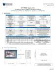
Carefully cut the host panel per the diagram on Page 1, creating a 189.7mm x 131.2mm ±0.1mm opening into which the XL7 may be installed. If the
opening is too large, water may leak into the enclosure, potentially damaging the XL7. If the opening is too small, the OCS may not fit through the
hole without damage.
3.
Remove all Removable Terminals from the XL7. Insert the XL7 through the panel cutout (from the front). The gasket needs to be between the host
panel and the XL7.
4.
Install and tighten the four mounting clips (provided in the box) until the gasket forms a tight seal (max torque 7-10 lb-in. [0.8 – 1.13 Nm])
5.
Reinstall the XL7 I/O Removable Terminal Blocks. Connect communications cables to the serial port, USB ports, Ethernet port, and CAN port as
required.
6. Ports & Connectors
Page 2 of 10