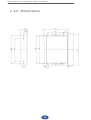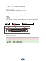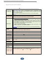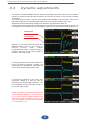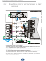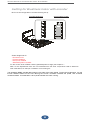
1
Service Manual for brushless DC motor drive BLD10
Version 02-15
BLD10 Service Manual
INTECNO s.r.l.
via Caduti di Sabbiuno n. 9/E
40011 Anzola Emilia (BO) Italy
tel. 051.19985350 fax 051.19985360
Service Manual for brushless DC motor drive BLD10
Version 02-15
2
Agency approvals
CE COMPLIANCE:
89/336/EEC Electromagnetic
EN 55011 Compatibility
EN 550082-1
98/37/EC Safety of Machinery
EN 60204-1
The EC mark that is applied to the drives references to the Low Voltage Directive (2006/95/EC)
and EC Directive on EMC (89/336/EC).
The standard EN 61800-5-1 is applied to ensure conformance with the Low Voltage Directive.
The standard EN 61800-3 is applied to ensure conformance with the EMC Directive.
In reference to noise immunity and noise emission the converters fulfi l the requirement to the category
second environment (industrial environment).
If the installation of the drive is carried out differently than described in this manual, the user must
carry out new measures to satisfy the requisites of law.
CONDITIONS OF ACCEPTABILITY
The devices shall be installed in compliance with the enclosure, moun ting, spacing, and segregation
requirements of the ultimate application.
These devices are intended as open type equipment. The need to repeat a temperature test shal be
considered in final end use application
These devices are suitable for field wiring
WARNING - Risk of damage and/or personal injury
This drive doesn’t contain any user serviceable part. Attempting to replace any internal component, may
result in damage to the unit and/or personal injury. This may also avoid the warranty.
All the informations and concepts included in this user guide are copyright, and are supplied to the
user with the understanding that it may not be copied, disclosed or duplicated in whole or in part for
any purpose not authorised by the factory. All specifications are subject to change without prior
notification.
Print in Italy 02/2015
2
Service Manual for brushless DC motor drive BLD10
Version 02-15
Index
Chapter 1
1.1
Safety and note
4
1.2
Operation mode and feedback
5
1.3
Characteristics
6
1.4
Product view
7
1.5
Ambient conditions
8
1.6
Ventilation
9
1.7
Power supply construction
10
1.8
Notes about connection
12
1.9
Connections to earth and ground
13
1.10
Dimensions
14
1.11
Pin ount overview
15
1.12
Internal adjustments
17
2.1
Brushless motor with Hall signals
19
2.2
Set up data for Intecno’s motors
21
2.3
Ramp time adjustments
22
2.4
Intecno motors’ connections
23
2.5
HW direction selection
24
2.6
Basic command diagram
24
2.7
Analog speed input
26
2.8
REQ torque input
27
2.9
Start input
28
2.10
Current monitor output
28
3.1
Speed offset adjustments
29
3.2
Trimmers adjustments
30
3.3
Dynamic adjustments
31
3.4
Brushless motor with encoder + hall sensors
32
3.5
Set up for encoder feedback
33
4.1
Indicator LEDs and protections
35
4.2
Troubleshooting
36
Resistance values decoding by the means of color’s
rings
37
Chapter 2
Chapter 3
Chapter 4
APPENDIX
A
3
Service Manual for brushless DC motor drive BLD10
Version 02-15
1.1 Safety and note
Caution
Users must take care that this motion control equipment is capable of producing high forces and
rapid movement so they must be used with attention especially during the application program’s
development.
This motion control equipments are sold as end-users products to be installed only by practical staff in
accordance with all local safety laws and regulations. The device have to be enclosed such that any
part is not be accessible while the system is powered on.
We strongly reccomend to follow these recommendations in order to avoid wrong uses of the equipment
that may be impaired all the protections provided by the device.
Please read these notes carefully before powering up the drive
It is very important to meet all applicable safety requirements during installation and operating of
any motion control equipment. Any installer has to assume the responsibility to ensure that he
recognizes and complies all the relevant safety standards. Any installation, not meeting the safety
requirements, may damage the equipment or injury the user.
This motion control equipment shoul be handled, installed, setted-up and maintenanced only by
competent personnel expert and trained in the installation of motion control electronic equipment.
Such technicians should be aware of potential electrical and mechanical hazards. Shall never beliable
or have any responsability if the products have been improperly stored, installed, used or maintened,
or if the costumer has permitted any unauthorized modifications, adjustments, and/or repairs to the
products.
Simbols security standard
Warning of dangerous current present
In case of doubt or in any case you don’t know as to behave yourself, before access to the
drive, power off the device and wait until all the LEDs are turned off.
May you have attention when you touch the drive because it may be hot.
Danger Sign
All the circuits in the Drive are potential sources of severe electrical shock, so follow these
rules to avoiding possible personal injury.
- Power off the drive and wait until all the leds are turned off before touching, removing,
connecting or any other critical action.
- Never disconnect any connectors before powering down the drive
4
Service Manual for brushless DC motor drive BLD10
Version 02-15
1.2
Operation mode and feedback
Description
This is a drive capable of piloting DC brushless motors.
It's a High Performance full four quadrant drive. The mosfet output power stage is controlled by a 20
Khz PWM (Pulse Width Modulation) signal that allows it to drive servo motors where high dynamic
performance and precise speed is required.
Operation mode
SPEED CONTROL
INPUT
TORQUE CONTROL
INPUT
DESCRIPTION
It is
speed piloting using an analogue
reference (differential or common mode)
It is torque piloting using an analogue
reference. This function allows you to control
the current from the drive.
STANDARD
STANDARD
General characteristic
START INPUT
FAULT OUTPUT
2 ANALOG
OUTPUT
LED INDICATOR
DESCRIPTION
Start input, enable the drive with range from
>9Vdc to +30Vdc (min/max)
Fault drive, open collector output 50mA max.
(Normally closed, opens when in protection
mode)
1 motor velocity monitor “TEST”, with range +/8 Vdc output
1 current monitor "CURR", with range +/-7 Vdc
output
Five LEDs are located just in front of the
potentiometers and show the current state of
the drive
STANDARD
STANDARD
STANDARD
STANDARD
Velocity feedback
Closing the velocity feedback loop to motor may be done in several different ways to accommodate
most applications.
• DC Brushless motor with Hall effect
(internal PWM Armature)
• DC Brushless motor with Hall effect +
encoder
5
Service Manual for brushless DC motor drive BLD10
Version 02-15
6
1.3 Characteristics
*
Type
Supply voltage
(Vdc)
Rated voltage
(Vdc)
Rated current
(A)
Peak currentt
(A)
BLD10
20 – 84 *
65
10
20 **
(*) Minimum and maximum voltage
(**) peak current lasts 2sec
Main technical data
FEATURE
VALUE
Supply voltage output
0,9 * Vdc input
PWM frequency
20Khz
Operating temperature
0/+40°C
Storage temperature
-10/+70°C
Drift analog input
+/- 0,5uV/°C
Analog inputs (+/-VEL)
+/-10Vdc max, impedance 20Kohm each.
Current monitor output (CURR)
+/- 7Vdc = peak current
Velocity monitor output (TP1)
+/- 8Vdc = max speed
Power supply output (+5V)
+5Vdc max 130 mA
Power supply output (+/-9,8V)
+/-10Vdc max. 4mA
Encoder max. frequency
300Khz with level >+2,8/24Vdc min/max
Fault drive output
NPN max. 50mA
Start input
+9V/+30Vdc (min/max)
Band width (current)
2KHz
Band width (velocity)
150Hz
Minimum Inductance motor
400uH
Weight
0,35 kg (10.6 OZ)
Altitude
Up to 1000m without restrictions, from 1000 to 2000m
power derating 1,5%/100m
6
Service Manual for brushless DC motor drive BLD10
Version 02-15
1.4 Product view
(1)
Product Label
(2)
Fixing screws
(3)
Cover
(4)
Solder bridges
(5)
Adjustment zone
(6)
N°4 calibration trimmers
(7)
LEDs
(8)
TEST point (Encoder, Armature velocity)
(9)
M1 Signal terminal 16 pins MC1,5/16-ST-3,81 (pitch 3,81)
(10)
POWER Terminal 5 pins GMST 2.5/5-G-5,08 (pitch 5,08)
2
1
3
4
10
5
6
8
7
This image does not faithfully reproduce
the product, has purpose just for
showing the parts
7
9
Service Manual for brushless DC motor drive BLD10
Version 02-15
8
1.5 Ambient conditions
Cable duct
50
135
5,3"
50
20
Ensure
circulation
the box
air
inside
20
Dimensions are
Cable duct
Conductive mounting
Conductive mounting panel
panel
Expressed in mm
(zinc coated)
Positioning in the electrical box
Follow the instructions in the positioning of the servodrive into the electrical box.
- The drive is naturally convection air flow cooled.
- To ensure the drive cooling and make the installation easier for the operator it must be installed
vertically leaving a free space of at least 20 mm (0,78 inch) on each side of the device. The converter
must be mounted vertically on the electrical box. In case you want to mount it horizontally, remove the
cover.
- The electrical box must have suitably filtered air vents.
- Leave the necessary space both above and below the converters.
- Keep the drive from excessive mechanical vibration
Notes during the assembly
Caution: during the wiring of the servodrive in the electrical box, make sure that do not enter leading
wires of copper or iron chips through the slits. Before performing the work cover the holes with a
piece of paper tape. Of course,after work it must be removed.
8
Service Manual for brushless DC motor drive BLD10
Version 02-15
1.6 Ventilation
This servodrives are intended only for use in close locations. Ambient characteristics: operating
temperature from 0 to +40°C. Humidity limit s between 5% to 95% non condensing (Pollution degree
2 or better).
Mounting position
NO
In case of horizontal mounting, take away
the cover.
YES
In case you agree to put also the fan, pls, put it under the drive
Standard heatsink +
fan under the drive
(operating temperature
0/+40°C)
9
Service Manual for brushless DC motor drive BLD10
Version 02-15
1.7
Power supply construction
Normally the power supply is built by a transformer, a bridge rectifier and a filter capacity. Alternatively,
the power supply can also be of switching type, in this case refer factory by the appropriate sizing.
The converter have to be supplied from an isolating rectified transformer secondary or a DC isolated
power supply.
Transformer
(T) TRANSFORMER
AC
POWER
INPUT
F1
AC
F2
+ C
V1
V2
+HV
VDC
AC
GND
Voltage:
The primary voltage depends on what is available locally for a single phase. The secondary voltage is
calculated from the motor’s voltage at the required operating speed.
The secondary voltage VDC is:
VDC = V2 * 1,41
Example: If the secondary transformer V2 is 45Vac, the VDC output is 45*1,41=64Vdc
PAY ATTENTION:
- The drive has zero signal GND in conjunction with the zero power GND, thereby preventing the
following links:
- Use a standard heavy duty power transformer without center taps on the secondary as shown in the
schematic above.
- DO NOT USE AN AUTO TRANSFORMER.
Power transformer (T)
The transformer's nominal power is calculated based upon the sum of power from the single motors
driven:
P(VA)=Pn1+Pn2+..
Pn Motor = N * Cn / 9,55
Where:
Pn Motor = Power absorbed motor in (W)
N
= Max. speed of motor in RPM.
Cn
= Nominal torque of motor in (Nm).
Note: In multi-axis applications, the transformer's power can be downgraded by 30%. If the max.
power transformer calculated is over 6KVA contact the factory.
Motor voltage
If the secondary voltage of power supply is VDC, the Vdc motor is calculated by the formula:
VDC = Vdc motor / 0,83
Where the Vdc motor is a sum of FCEM + the drop R*I for the winding resistance motor
Vdc motor = E+(Ri * In)
10
Service Manual for brushless DC motor drive BLD10
Version 02-15
The FCEM of the motor "E", may be calculated by the formula: E = Ke * N° / 1000
Example: Brushless motor with the following data:
In =5 (A)
Ri = 1 (Ohm)
E=48 (V) at nominal speed 3000 (RPM)
Vdc motor = 48 + ( 1 * 5) = 53V
VDC = 53 / 0,83 = 63,8V
63,8V is the VDC voltage request for the power supply. You'll use a transformer with the secondary
V2 = 64 / 1,41= 45Vac
When you use the transformer with V2= 44/45Vac, it is correct.
Misure unit:
E = Ke *n°/1000 (Vdc)
Im = I motor (A)
Ri = Winding resistance (Ohm)
Ke =Voltage constant (V/kRPM)
n° = MAX speed (RPM)
Capacitor filter(C)
In regards to the capacitor filter we suggest a working voltage of:
*100VDC
*Tipical value is from 4700uF to 10.000uF (depending on the motor size and kind of application)
Capacity above the filter effect, helps to recover energy during braking of the motor.
If the converter during braking has the green LED that flashes you must increase the value of the
capacitor (eg. 10.000uF from a 20.000uF)
Fuses (F1) e(F2)
Fuses are required on both the primary and secondary of the transformer to protect against harm to
the system and the transformer itself. They need to be of the slow blow type to handle current in-rush
at power-up. Locate the primary fuse (F1) on the hot leg of the AC input power and the secondary fuse
(F2) on the + side of the secondary output, before the rectifier.
Primary of the transformer, use the formula below to calculate the correct values:
F1 (A) = P (VA) trasfo. / V1
Secondary of the transformer: Use the table below
FUSE F2 (A)
12
16
MOTOR TYPE
BL0120.240, BL180.240, BLS022.240, BL025.24E, BL032.240, BL043.240, BLS043.240
BL070.480, BL070.48E
11
Service Manual for brushless DC motor drive BLD10
Version 02-15
18
1.8
Note about connections
Multiple connection
In the case of multiple servodrives on the same power supply, make connections-type stars, see
drawing back. Connect also feed converters using the shortest cable possible. If the cable length
exceeds 2m, twist the + and - leads together as twisted pairs.
NO
+
Power supply
YES
+
+
+
-
-
-
+
-
+
+
-
-
+
Power supply
The drives have to be supplied from an isolating rectified transformer secondary or a DC isolated
power supply.
EMC note
The conformity is assured only if it is installed following the precise assembly criteria expressed
below. The fundamental assembly characteristics are summarized below:
*
The correct ground connection of predisposed parts.
*
Using the division of cables technique. Separate power cables from signal cables.
*
Use of shielded cables, both for power connection (to the transformer and the motor), and for
signal connection (also to the controller).
*
Use of appropriate network to filter the line (transformer input), from disturbances conducted or
produced by the drive. (series of filters released are available for this purpose).
12
Service Manual for brushless DC motor drive BLD10
Version 02-15
1.9
Connection to earth and ground
Make sure that the servodrive and the motor are connected to earth in accordance with the current
norms. This connection must be done by using a copper bar, mounted on insulating supports.
Ground bar
Earth point connection
L bar
L bar
0,5 .. 1m
1..2m
Bar's section
30 x 5 mm
40 x 5 mm
then follow these indications:
1. Connect to the ground bar:
the internal "0V" zero voltage of the
CNC; the earth terminals of the
PLC/CNC frames; the "0V" of the
auxiliary supply;
the CHASSIS of all drives;
2. Connect the ground bar to the zinced panel of the drive by using a screw, then connect that
screw to earth.
3. Connect earth to the motor’s
It suggests a conductive connection as much as possible to the chassis, or the
heatsink, or the mounting panel of the electrical box.
It refers to the earth connection.
Motor and Power cable (as norm EN60204), in case of needing to have longer
cable than standard ones
WIRES SECTIN
MOTOR TYPE
1,5mm2 / 15AWG
BL012.240, BL018.240, BLS022.240, BL025.24E, BL032.240,
BL043.240, BLS043.240
2,5mm2 / 13-14AWG
BL070.480, BL070.48E
Control signals cable (as norm EN60204)
WIRES SECTION
0,5mm2 / 20AWG
Feedback signals cable (as norm EN60204)
WIRES SECTION
0,25 - 0,35mm2 / 22 -24AWG
13
Service Manual for brushless DC motor drive BLD10
Version 02-15
1.10 Dimensions
14
Service Manual for brushless DC motor drive BLD10
Version 02-15
1.11 Pin out overview
Pin out view
The figure below shows the view of the converter terminals.
M1 Signal terminal 16 pins "type MC 1,5/16-ST-3,81" POWER
Terminals 5 pins "type GMST 2,5/5-G-5,08"
On the test point "TEST" you can see the signal of speed. The output from 0 to + /-8V is from zero to
maximum speed. At this point you can analyze the signal when you enable one of the following velocity
feedback.
• Encoder
• Armature
NOTE: Depending on the type of motor to drive, follow the links relating to such applications.
Trimmer
Signal I/O
Power input
Power terminals
+HV (IN)
GND (IN)
U (OUT)
V (OUT)
W (OUT)
POWER CONNECTOR
Positive Power supply input
Negative Power Supply input (GND)
Motor connection U phase
Motor connection V phase
Motor connection W phase
NOTE: pls, read also the connection diagrams of the following chapters.
15
Service Manual for brushless DC motor drive BLD10
Version 02-15
Signal inputs and outputs
1 CURR / IN2
M1
This signal can be used in 2 distinct modes:
Current motor monitor (OUT): +/-3.5Vdc=Rated current, +/-7Vdc=Peak current
output in Volts. This output may be used to monitor the torque the motor is
producing (Standard setting)
IN2 setting (IN): Is possible setting this terminal for Limit sw input (contact
Intecno)
2 FAULT (OUT)
Fault drive, open collector output max. 50mA
Normally closed, opens when the drive in protection mode
3 REQ / IN1
REQ:, can be used in 2 distinct modes:
1) Motor Current limit mode (by REQ setting):
A motor current limit mode connect an external resistor to GND reduces the
maximun current. Connect a 1/4W o 1/8W resistor between the TPRC (pin
3) and GND (pin 4) terminals. A 47Kohm external resistor reduces the current
by 50%. (Note: The drive speed loop remains active)
2) Torque request (by REQ setting):
Range: +/- 10V, which corresponds to the drives peak current output. In this
mode the speed loop is automatically disabled.
IN1 setting (IN): It’s possible to set this terminal for Limit sw input (contact factory)
4 GND
Signal Common Ground
It corrisponds to power supply's negative GND input
5 +10V (OUT)
Power supply +10Vdc max 4mA
6 –10V (OUT)
Power supply –10Vdc max 4mA
7 START (IN)
8 +VEL (IN)
Positive drive enable, with range >+9Vdc min. to +30Vdc max
Reference Positive differential input (Speed command)
9 -VEL (IN)
Reference Negative differential input (Speed command)
10 ENC A
Encoder input Channel A (High logic level from >2,8V to +24Vdc max. Low logic
level <1,5V).
11 ENC B (IN)
Encoder input Channel B (High logic level from >2,8V to +24Vdc max. Low logic level
<1,5V)
12 +V (OUT)
Power supply +5V max. 130mA
13 GND
14 HALL 1 (IN)
15 HALL 2 (IN)
Signal Common Ground. It corrisponds to power supply's negative GND input
Hall Sensor inputs from the motor. Each input has a pull-up resistor of 1 Kohm to
internal +5V (High logic level >3,2V , Low logic level <1,5V)
16 HALL 3 (IN)
16
Service Manual for brushless DC motor drive BLD10
Version 02-15
12
1.12 Internal adjustements
If changes need to made to the internal drive setting powering, please wait at least 30 seconds after
the power has been removed and the OK LED is off.
All of the personalizations are located inside of the DRIVE. (See figure above)
To get the access to the adjustment pads and the Solder bridges, unscrew and remove the cover.
Solder point standard configuration
Solder bridges standard position are setting by factory for:
- Brushless setting
- Hall sensor feedback
- Ramp time disabled
- Standard Dynamic constant
17
Service Manual for brushless DC motor drive BLD10
Version 02-15
Adjustement zone
FEATURES
RDT
RENC
Non used
RIP
Encoder resistor adjustement
Armature resistor adjustement
Drop compensation for internal motor resistance (RI)
Drive rated current resistor
Drive peak current resistor
RKV
Resistor value that respectively form the proportional/integral network of the velocity Loop
gain. Disabled by opening solder bridge S4. Standard value 100k and 47nF.
RA
RCA
RIN
RACC
Changes static gain in the velocity loop. Open solder bridge S5 and insert RGAIN if a
change is required. Consult factory for the correct value.
Resistor for setting acceleration time function. See Chapter 2.3
CKV
Capacitor value that respectively form the proportional/integral network of the velocity Loop
gain. Disabled by opening solder bridge S4. Standard value 100k and 47nF.
GAIN
CDER
Derivative constant capacitor, increases the velocity loop derivative constant.
Consult factory for the correct value.
Solder bridges
Note: For any feedback available, are listed in the various chapters related settings (read chapters 2)
SOLDER BRIDGES
1
2
3
4
5
6
7
8
9
10
11
Normally open (OFF)
Normally closed (ON) Don’t touch
Normally open (OFF) See Chapter “Ramp time adjustment”. If closed insert RACC resistor
Normally closed (ON) Open= install components in the adjustment zone, for the dynamic
velocity value CKV and RKV. (Standard value RKV=100Kohm , CKV= 47nF).
Normally closed (ON) If Open you must insert the GAIN resistor. (Static Gain). Standard
value= 27 ohm
Normally open (OFF) If closed, when the IxT protection operates the green led OK (and the
output FAULT) goes off.
Normally open (OFF) If closed the drive is set is for the armature feedback. Insert also the
resistance RA and RCA
Normally closed (ON) In this position the drive is set for the encoder feedback. If Open (OFF),
other types of feedback are enabled
Normally open (OFF) If closed setting the drive for PWM+DIR command (optional)
Normally closed (ON) Open S10 (OFF) for tachogenerator feedback
Normally closed (ON) If open (OFF), the alarm protection for missing Hall Effect Signals will
not disable the drive.
18
Service Manual for brushless DC motor drive BLD10
Version 02-15
2.1 Brushless motor with hall signals
The following diagram shows a tipical application utilizing a Drive with Brushless motor (only
Hall signals).
These signals are used in the converter for the control of current and to regulate motor speed. The
adjustment range is lower than the use of 'Encoder + Hall, but good enough for many applications
19
Service Manual for brushless DC motor drive BLD10
Version 02-15
Setting for Brushless motor with hall signals
In this configuration, BLD10 must set with the following Solder bridges and below internal setting:
SOLDER BRIDGES
ADJUSTMENT ZONE
2Standard solder Bridges set for:
- Hall feedback (Armature)
- Ramp time disabled
- Standard Dynamic constant
- Brushless motor
For the correct value of RA and RCA resistor (speed adjustment range) see chapter 2.2
Note: On the adjustement zone the other components are not considered here, the ones used to determine
other calibrations, for example. Calibration current rating etc.
20
Service Manual for brushless DC motor drive BLD10
Version 02-15
2.2
Set up data for Intecno’s motors
BLD10 is set up by default on the motor BL043240. Hall sensor feedback.
In order to set up the drive to other motors, pls, change the resistors as the table below.
BLD10 (basic = 10/20 A)
Motor type
Current [A]
(rated/peak)
Motor voltage
[V]*
Rin [Ohm]
Rip [Ohm]
RA [Ohm]
RCA [Ohm]
BL012 240
3,5/7
24
820R
27K
4K7
68K
BL018 240
5/10
24
1K5
47K
4K7
120K
BL022 240
7/14
24
3K9
120K
4K7
120K
BL025 24E
7/14
24
3K9
120K
4K7
180K
BL032 240
5/10
24/36
1K5
47K
8K2
150K
BL043 240
7/14
24/36
3K9
120K
8K2
220K
BLS043 240
7/14
24/36
3K9
120K
8K2
220K
BL070 480/48E
7.5/15
48
---
---
18K
470K
* Supply the drive with 5-6 Vdc more than the rated motor voltage.
Keys:
Rin = rated current limit resistor
Rip = peak current limit resistor
RCA = voltage drop calibration resistor
RA= max speed calibration resistor
Rip
Rin
RCA
RA
See Appendix A (page 37) the decoding of the values of resistances by the method of colored rings.
21
Service Manual for brushless DC motor drive BLD10
Version 02-15
2.3
Ramp time adjustements
The product is (standard) set with this feature not enabled (Section S3 open)
To enable the ramp acceleration, close the solder bridge S3 and insert the RACC resistance. NOTE: The product
issupplied by default with mounted 470ohm resistance value (0.8 sec ramp)
Ramp disabled (standard setting)
VEL
+3,3V
T
-2V
MOTOR
T
Ramp disabled
Ramp enabled
VEL
+3,3V
T
-2V
MOTOR
T
Ramp enabled
Table
The time shown on the right are
related to a change to step on the
reference signal input + /-VEL of 10V.
Example from 0 to 10V or 10 to 0V
Resistance (ohm)
27 Ohm
68 Ohm
100 Ohm
470 Ohm
1K Ohm
1,5K Ohm
3,3K Ohm
10K Ohm
22
TIME (seconds)
15
5
3,16
0,8
0,32
0,26
0,16
0,086
Service Manual for brushless DC motor drive BLD10
Version 02-15
2.4
Intecno’s motors connection
Pls, follow the drawing:
Power wires (bigger section)
Yellow big (or blue) phase motor U
Red big (or brown) phase motor V
Black big phase motor W
Signal wires (smaller section):
Red small (+Vdc)
Black small (GND)
Blue (hall U)
Green (hall V)
White (hall W)
: pin U
: pin V
: pin W
:
:
:
:
:
pin
pin
pin
pin
pin
12
13
14
15
16
Just for motor BL070480/BL07048E, power wires colors can be different, but the
signal wires’ colors are the same as the other motors
DRIVE
MOTOR
(only BL070480-48E)
Big wires: power
Blue=
pin U
Brown = pin V
Black =
pin W
+HV
GND
U
V
W
23
Service Manual for brushless DC motor drive BLD10
Version 02-15
Connection picture as per example. Use shielded wires in case you need longer wires.
2.5
HW direction selection
In order to get the change of direction of the motor, without using the feature of inversion by the drive,
the user can procede as follows:
a) Change each other the position of the motor phases U and V (yellow with red)
And at the same time:
b) Change each other the wires of the Hall signal pin 14 and pin 16 (blue with white)
2.6
Basic command diagram
NOTE: close pin 7 onto pin 5 (or connect to pin 7 a voltage from 10 to 24 Vdc). This enables the motor
to run as per speed selected by the speed pot. Start pin does not meet the ramp (even if the ramp is
enabled). Opening pin 7, the motor stops by coast.
5 +9.8V
7 START
24
Service Manual for brushless DC motor drive BLD10
Version 02-15
The simpliest basic connection is the following:
1
5 +9,8V
0
6 -9,8V
2
Speed pot
8 +VEL
4 GND
10 KOhm speed pot, the central pin (the one that changes) connected to pin 8 (+VEL), one of the
external pins to the pin 4 (GND) and the other to a 3-ways selector, that is connected itself as per the
picture.
0 = stop
1 = run forward
2 = run reverse
Speed is managed by the speed pot, the direction by the polarity of the selector.
25
Service Manual for brushless DC motor drive BLD10
Version 02-15
2.7
Analog speed input
Differential reference
(+/-VEL) This analog in differential mode has a 40Kohm of impedance input.
The following diagram shows an application utilizing a differential reference from a C.N.C
CNC
DRIVE
Common mode reference
This analog in common mode has a 20Kohm of impedance input.
The following diagram shows an application using speed reference connections from C.N.C in the
Common Mode.
CNC
DRIVE
Speed reference from external potentiometer
The following figure shows an application with speed reference connections using an internal +/-10V
power supply.
The speed potentiometer must have an included value between >5 and <10Kohm.
Speed pot
DRIVE
26
Service Manual for brushless DC motor drive BLD10
Version 02-15
2.8 REQ torque input
Current command mode
With a voltage (example from a CNC output) you can command the drive in torque mode.
CNC
DRIVE
Applying a signal of +/-10V at TPRC, the user enables the drive to supply positive or negative peak
current.
The formula to determine the value of Voltage to apply in TPRC in order to obtain requested current is
the following:
V(TPRC) = 10 * Request current / PKcurrent Drive
Example: (Drive size 10/20A, request current 8A)
V(TPRC) = 10 * 8 / 20 = 4V
NOTE:
In current reference the loop of internal speed is automatically excluded.
In order to get a current +8A a voltage -4V in REQ pin must be applied, in order to get a current -8A a
voltage +4V must be applied.
Non apply voltage more than ± 10Vdc on REQ pin.
Current limit mode
With an external potentiometer connected from GND and TPRC input, you have a limitation of output
current (from zero to max. size) drive's.
CNC
DRIVE
Suggested speed pot
(470K-1M Ohm)
The speed ring remains active and uses the input reference signal. In this case the loop of internal
velocity remains active.
Applying and eternal resistance tending to zero Ohm, allocable current tends to zero. Encreasing he
resistance, allocable current encreases too. 47Kohm current is limited by 50%
Speed loop is active.
27
Service Manual for brushless DC motor drive BLD10
Version 02-15
2.9 Start input
The standard drive is supplied in this configuration.
Start enable input has logic range: >+9V to +30Vdc (min/max)
CNC
DRIVE
Unconnected Enable input = Drive Not Enabled
Enable Input +24Vdc = Drive Enabled
Is possible to enable the drive connecting the START input to +10V output "terminal 5"
2.10
Current monitor output
CURR analog output (pin1)
On this terminal is available analog output "current monitor of motor" with range 0V + /-7V. The value
of 7 V is the maximum current supplied by the drive. For example, if we have a size 10/20A,
7V corresponds at 20A circulating on the motor.
The signal can be positive or negative depending on the direction of rotation of the motor.
Output Impedance is 10Kohm. Consider the internal impedance in the case are linked external resistive
divider.
Drive
Multimeter
1,27
Note:
Standard product is set to the signal CURR on terminal 1 (reading of the current circulating on the motor)
and the REQ input at terminal 3.
If these signals are not used, you can use these terminals for two other control functions named IN1 and
IN2.
Through the inputs IN1 and IN2 (when set) you can limit the motor torque in the two respective
directions of rotation of the motor (CW and CCW). Can therefore be used as limits Overtravel left and right.
Ask how to set these inputs in the factory.
28
Service Manual for brushless DC motor drive BLD10
Version 02-15
3.1
Speed offset adjustments
For this adjustment both Hall and Encoder signals are required.
The converter is supplied with zero adjustment already performed in encoder feedback. If necessary, turn
the Offset trimmer, to correct any offset error. (It makes up approximately +/- 200mV on the reference input
+/- VEL). With the reference input to zero, turn the trimmer, till to stop the motor.
This calibration works with any type of speed feedback adopted
3.2
Trimmer adjustments
The converter is equipped with 4 trimmer with the following meanings:
29
Service Manual for brushless DC motor drive BLD10
Version 02-15
FEATURES
Motor fine speed calibration. With rotating clockwise (CW) or counterclockwise
(CCW) is possible increase / decrease the speed of the motor with range + / -25%
Offset adjustment. Allows the balance to zero motor speed. Adjust this
OFFSET
potentiometer to cancel any motor speed offset when the Velocity input is zero.
(Max
compensation
+/- 250mV).
Gain Velocity
potentiometer.
This adjustment
improves the dynamic behavior of the motor.
SPEED
GAIN
With a clockwise (CW) we increase the readiness and response of the motor. With a
clockwise turn (CW) we increase the gain of the PI “internal speed loop”.
DERIV.
Derivative potentiometer. Acting in a clockwise (CW) can dampen any
oscillations of the motor due to a high moment of inertia of the load.
In Chapter 3.3 explains how to dynamically tune the motor by acting on the 2 trimmer GAIN and
DERIV.
All potentiometers are disabled in Torque mode
30
Service Manual for brushless DC motor drive BLD10
Version 02-15
3.3
Dynamic adjustments
The multi-turn GAIN and DERIV trimmer allow to dynamically tune of the motor and its mechanics
linked to it. These trimmers have full excursion from minimum to maximum, with 15 turns of rotation
of the same.
The charts shown the track 1 "yellow" is the speed signal available in the point TEST. Track 2 blue
highlights instead the current signal taken at terminal 1 (M1 signals connector pitch 3.81)
Signals are reported with a step voltage of the reference signal speed of about 2V.
These signals can be displayed by connecting the two probes of an oscilloscope at those points. The
zero signal 0S (zero probes) can be connected by a wire to pin 4 (M1 signals connector pitch 3.81)
.
Speed signal
Current signal
Behavior of the motor with both GAIN and
DERIVATIVES trimmer to a minimum of
function
(trimmer
totally
rotated
counterclockwise CCW). The speed signal is
unstable, the same for the current signal of
themotor. See chart at right
Turning clockwise CW the trimmer GAIN (4 / 5
turns) the dynamic behavior improves, not
exceed with this adjustement, otherwise the
motor will be vibrating. See chart at right
To improve the behavior of the motor and
mechanics related to it and the over all
damping of the speed signal oscillation , act
trimmer DERIV. turning it clockwise CW (4 / 5
turns). See chart at right
NOTE: The dynamic calibrations are performed
using a reference speed (in + /-VEL) of about 1
or 2V. You can use the voltage output from the
CNC control, paying attention to rule out the
correction of space. Or use an external oscillator
or a small battery 1.5 V
31
Service Manual for brushless DC motor drive BLD10
Version 02-15
3.4
Brushless motor with encoder + Hall
sensors
CNC
DRIVE
In the figure above is shown a typical connection.
The encoder with line driver output is connected directly to the control. Depart from the control wires
A +, B +, GND to the converter (signals in common mode).
In the example the encoder is supplied by the CNC, while the hall sensors are supplied by Drive
(+V terminal 12).
It’s also possible to supply the encoder with the voltage present on the +5V of the drive (+V terminal
12), verifying that the absorption of the encoder does not exceed 100mA.
The converter is ble to provide 130mA max (100mA for encoder and 30mA for Hall sensors)
Hall sensors must be supplied using the internal +5V of the Drive (M1 connector 12). If an external
supply is used, open solder bridge S11
32
Service Manual for brushless DC motor drive BLD10
Version 02-15
Setting for Brushless motor with encoder
BLD10 in this configuration must have following set up:
SOLDER BRIDGES
ADJUSTMENT ZONE
Solder Bridges set for:
- Brushless motor
- Encoder feedback
- Ramp time disabled
- Standard Dynamic constant
For the correct value of RENC resistor (speed adjustment range) see chapter 3.1
Note: On the adjustement zone are not considered here the other components used to determine
other calibrations, for example: Calibration current rating etc
The resistance RENC inserted determines the full scale of the motor speed. To have a fine calibration, turn the
trimmer SPEED located on the front. Moving the trimmer clockwise increases the speed, and viceversa
counterclockwise. This calibration is to be performed with the motor running.
33
Service Manual for brushless DC motor drive BLD10
Version 02-15
3.5
Set up for encoder feedback
This speed feedback allows the adjustment of the motor speed, using the signal from an incremental
encoder two channels A and B. The signals from the encoder are read in a common way. The logical
value of these inputs must be in the range of> + 2.8 / + 24V (minimum and maximum)
To get good dynamic performance on the motor, we recommend the use of encoders with at least
2000 / 2048PPR. Acceptable performance is obtained, however, even with the use of the encoder 500
/ 512PPR. The settings and calibrations already shown in their respective sections enable the reaction
encoder.
Even if the encoder is mounted, Hall signals are always necessary to be connected.
RENC resistor calculations
The drive is set with solder bridge S8 closed and the resistance calibration speed RENC mounted
on board "27Kohm" (Calibration for speed = 3000rpm encoder with 10V reference and 500PPR
line-count resolution encoder.)
In order to change this resistance, open the drive and calculate the following formula:
RENC = 681*1000000 / Fenc
The resistor RENC determine what is the max. speed of the motor at 10V of reference.
Where:
Example:
Fenc = PPR * RPM / 60
N° encoder pulses = 1000 PPR
Motor speed = 3000 RPM
RENC = 681*1000000 / 50000 = 13,62 kohm
The result of RENC resistance is 13 K. Preferred resistance with 1% tolerance.
Once the resistor RENC is inserted, proceed with final speed adjustment.
Operate using trimmer SPEED on the front of the drive. With Clockwise Rotation the speed
increases. With Counter Clockwise Rotation the speed decreases. The Range of regulation is about
+/- 20%.
36
34
Service Manual for brushless DC motor drive BLD10
Version 02-15
4.1
Indicator LEDs and protections
The protections are all displayed by five LEDs on the front of the drive. It also comes with a series of
protections designed to safeguard the drive and the motor in case of malfunction.
OK
GREEN
FEATURES
Normally ON. Indicating the proper operation of all functions. It turns OFF in case of
any anomaly "except protection intervention IxT". The faults that affect this LED are:
Over/Under input voltage. Over temperature (PTC).
IxT
RED
Normally OFF. This indicator is lit if the converter exceeding the limit calibration of
the rated current of the motor. When the current drawn back under the nominal preset, the alarm will auto resets and the LED turns off by itself.
PTC
RED
O.C
RED
H.ALL
RED
Normally OFF. This indicator is lit when the internal temperature of the drive reaches
75°C . Remove power and wait for the drive to cool before re-applying power. The
operation causes the blocking of the drive and the storage of the alarm. NOTE: A fan,
heat sink or air conditioner may be needed to remedy the problem.
Normally OFF. Indicates that between the motor terminals and/or ground, has been
a short circuit. The operation causes the blocking of the drive and the storage of the
alarm. Remove power supply and examine the motor connecting leads for shorts,
before re-powering the converter to reset the alarm.
Normally OFF. If lit, it indicates that the Hall signal is missing, or the power supply
+5V is missing. Check the Hall signals with a voltmeter or an oscilloscope.
In chapter 4.2, it explains the possible reasons for the alarms of the converter.
35
Service Manual for brushless DC motor drive BLD10
Version 02-15
4
4.2
Troubleshooting
Possible causes for the alarms
- When power supply is on the green OK LED doesn't come on. Check the voltage between +HV
and -GND with a tester.
- During deceleration of the motor, the LED green blinks. Increase the capacity filter. (example
from 10.000uF to 20.000uF)
- LED lights red O.C. Check the connections U, V, W a short circuit can be between two of
these wires, between one of these wires and ground, or short circuit inside the motor or the
motor cables.
- LED lights red ixt. Excessive mechanical load
- LED lights red PTC. Ambient temperature too high, or the converter does not have a minimum
circulation of air cooling, ventilation or missing where expected from the size of the converter.
- At Startup or Enabling the H.ALL Led comes on. One or more missing Hall Signals. Missing
power supply to Hall Cells.
- With the green LED the motor will not start when you enable the drive with START
Check for the enable signal START. Also verify the presence of the speed signal between the
terminals + /-VEL
- Motor goes out of control when enabled.
- Encoder signals incorrectly connected (ENC A and ENC B signals swapped, or encoder
power supply missing, or signals swapped)
36
Service Manual for brushless DC motor drive BLD10
Version 02-15
APPENDIX A
RESISTANCE VALUES DECODING BY THE MEANS OF COLOR’S RINGS
The resistances taken for calibration are “4 rings type” as photos.
For the decoding of the ohmic value, use the following table.
First ring = tens digit
Second ring = unit digit
Third ring = multiplier
Fourth ring = tolerance
COLOR
1° RING
2° RING
3° RING
4° RING
Black
-
0
x1
-
Brown
1
1
x 10
-
Red
2
2
x 100
-
Orange
3
3
x 1.000
-
Yellow
4
4
x 10.000
-
Green
5
5
x 100.000
-
Blu
6
6
x 1.000.000
-
Violet
7
7
x 10.000.000
-
Grey
8
8
-
-
White
9
9
-
-
GOLD
-
-
: 10
5%
SILVER
-
-
: 100
10%
NOTHING
-
-
-
25%
For example, the resistance in the picture:
Brown = 1 (tens digit)
Black = 0 units digit
Red = Multiplier x 100
Gold = 5% tolerance
10 x 100 = 1K, 5% tolerance
37