1
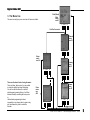
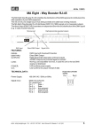
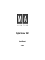
Digital Dimmer WM
User's Manual
03.2005
Contents
2
1.
Introduction
2.
Reference / Controls
3.
The Menu tree
4.
The menus
4.1
The main menu (top menu)
4.2
The channel menu (2nd menu)
4.3
The Memory menu (3rd menu)
4.4
The Setup menu (supervisor menu)
4.4.1 DMX Fail (reaction on failing DMX signal)
4.4.2 DMX MODE
4.4.3 CLEAR CURVES
4.4.4 USER MODE (limiting the dimmer control)
4.4.5 DELETE ALL
4.4.6. and 4.4.7 CURVE USER (creating user-defined trigger curves)
4.4.8 PHASE CORR. (activating phase correction)
5.
Error messages / malfunctions
6.
Startup
6.1
Mains connection and earthing
7.
Dimensions and weights
8.
Inputs and outputs
8.1
DMX inputs and outputs
8.2
External keyboard (not supplied)
8.5
Power supply
8.6
Load outputs
9.
Opening the dimmer (service)
10.
Important safety instructions
11.
DECLARATION OF CONFORMITY
12.
Appendix
13.
Design models
Index
MA Lighting Technology GmbH . Dachdeckerstr. 16 . D-97297 Waldbüttelbrunn .
www.malighting.de
3
4
5
6
6
8
10
12
12
13
13
13
14
14
15
16
17
18
19
20
20
20
21
21
22
24
25
26
29
30
eMail: [email protected]
D i g i t a l D i m m e r WM
1. Introduction
The MA DIGITAL DIMMER WM consists of a very sturdy outer casing containing a 32 bit highperformance computer plus a „time-processing unit“ and a large graphics display. This lavish technology
will enable you to use versatile and new opportunities:
-
simplified use by few, clear menus
free assignment of DMX addresses for any channel
free programming of trigger curves
internally saved memories with fading capacities
internally saved chaser with fading capacities
calling up of e.g. memories on failing DMX signal
calling up of memories from an external keyboard (optional)
different user restrictions
overvoltage and over-temperature warnings and switch off with acoustic signalling
display of incoming signals, phase voltage, memories, etc.
The MA DIGITAL DIMMER WM functions according to the phase control process using thyristors. In
this process, technique-depending harmonics, especially in lower frequency ranges. These harmonics
are being effectively suppressed by an excellent interference elimination based on special design
filters.
By using a special core material, the filters’ heat dissipation could be reduced dramatically. The
remaining heat is being removed by a temperature-controlled fan.
This guarantees for a 100% steady-load resistance.
The short circuit protection for the individual channels is guaranteed, for example, by Siemens safety
cut-outs and thyristors having a surge current capacity of more than 1000A.
The ready-made integration of DMX512 into various basic configurations has a great potential in
multiple operational fields.
As opposed to the MA DIGITAL DIMMER, the WM (WallMount) version is intended to be used with
permanent installations. Both dimmers are identical in their essential functionality.
Hotline.: + 49 5251 688865-99.
User's Manual Digital Dimmer WM 05.2005
3
2. Reference / Controls
Upper bulkhead
cable gland
Control
lights for
phases
L1,L2,L3
Display
Left key (A)
with red LED
Menu key (switches
to next menu) with
green LED
Mount dimmer in a rack or on the wall. Please observe
weight and required space for cable entries and outlets.
Always provide for a sufficient ventilation; supply and
exhaust of cooling air has to be ensured !
Connect load cable and trigger cable. Observe the
general safety instructions and utility regulations !
Electrical wiring may only be made by authorised
personnel.
Right key(B)
with red LED
12 safety cut-outs
(behind transparent cover)
Check list for urgencies:
Set the DMX addresses (see p. 8)
Set the memories (see p. 10)
Set DMX Fail (consequence of a failing control input
signal; see p. 12)
If needed, assign memories or the Chaser to the
(optional) keyboard (see p.10)
Mounting
bracket
Tasten für memories (optional)
Air inlets for fans
Encoder (DatenEingaberad)
Lower bulkhead
cable gland
4
MA Lighting Technology GmbH . Dachdeckerstr. 16 . D-97297 Waldbüttelbrunn .
www.malighting.de
eMail: [email protected]
D i g i t a l D i m m e r WM
Start (Reset)
Main
menu
see 4.1
3. The Menu tree
The menu tree will give you an overview of all menus available.
A
Menu
B
Hold for 5 seconds
Channel
menu
see 4.2
Cha.
A Menu
B
Setup
menu
see 4.4
Version
A Menu
Memory
menu
see 4.3
B
000,3
Go
Menu
B
A
These are the basic facts of using the menu:
There are three „basic menus“ you can switch
to using the middle key below the display.
You can use the Encoder with or without
simultaneously pressing the key; it will then
behave differently, according the menu you’re
in.
Unintentional programming is almost
impossible, as you always have to press a key
and, simultaneously, have to rotate the
Encoder.
Chaser
menu
see 4.3
Curve
menu
see
4.4.9
Save
A Menu
B
Save
A Menu
Hotline.: + 49 5251 688865-99.
B
User's Manual Digital Dimmer WM 05.2005
5
4. The Menus
The back-lit LCD is on front side of the dimmer.
By using the three keys below the display and the rotary switch (so-called Encoder or data
entry wheel) you can set parameters as e.g. DMX addresses, limits, trigger curves, preheat,
etc.
Generally, you can switch to the next of 3 menus by pressing the middle key below the display.
Data will be entered using the Encoder and the other two keys.
For more detailed information, see the respective chapters.
4.1 The Main menu (Top menu)
After switching the dimmer on or after plugging it in, the main menu will appear on the display.
This menu is the standard menu in normal operation mode. This is where the different status
and error messages, as well as the modulation of individual channels are displayed.
And, within these menus, you can set one or more channels to specific values (setting the
lights).
DISPLAYED VALUES:
- bars:
numbered channels from 1 to 12 (numbering cannot be changed)
dark = external modulation
bright = internal modulation (e.g. by a saved Memory)
The Dimmer works in HTP mode (Highest Takes Precedence), i.e. only the higher
value derived from an external or internal modulation will be output.
- L1-3:
displayed voltage of the three phases L1 (ch. 1-4), L2 (ch. 5-8), L3 (ch. 9-12)
- D:
DMX address of the first channel (in the BLOCK setting, the following channels
are numbered in ascending order)
- T:
internal dimmer temperature in degrees Celsius
- Current: displays the running or last called Chaser or Memory
- Status:
- DMX OK = DMX signal is being received
- NO DMX = no DMX input signal (on the right, the current output is displayed.
Can be set by DMX-FAIL)
- Value:
shows the temporary, not saved value of the selected channel. For a running
Chaser, a started Memory or an externally entered value, the channel value will
no longer be displayed.
- CHA:
shows the selected channel (1-12)
- SET:
shows the set preset value; this value can be transferred to all channels (see
„setting channels“).
6
MA Lighting Technology GmbH . Dachdeckerstr. 16 . D-97297 Waldbüttelbrunn .
www.malighting.de
eMail: [email protected]
D i g i t a l D i m m e r WM
SETTINGS:
- Select a channel
Press the MENU key, until the main menu appears
Press the Encoder, until the desired channel number is displayed
- Setting values
Press the MENU key, until the main menu appears
Rotate the Encoder, until the desired channel number is displayed
Rotate the Encoder and hold down the A key, until the desired value is set.
Rotate the Encoder, until the next desired channel number is displayed
Hold down the A key and simultaneously rotate the Encoder, etc.
- Copying a setting to another channel
Hold down the B key and set the desired value by using the Encoder
Rotate the Encoder, until the desired channel is selected
Press the B key shortly, to transfer the set value to the channel
- Deleting all settings (only temporary setting will be deleted; if, for example, a Memory is
running, the displayed values cannot be deleted using CLEAR ALL).
The display of the left key will also indicated „CLAR ALL“.
Hold down the B key and press the A key
Important:
This channel setting will not be saved permanently, but be reset to zero after switching the
dimmer off. For the lighting on fairs etc., please use the internal Memories, as they will be
kept even after a power failure or after switching the dimmer off.
Hotline.: + 49 5251 688865-99.
User's Manual Digital Dimmer WM 05.2005
7
4.2 The Channel menu (2nd menu)
Here, for any channel (1-12) you can set
- the DMX address
- a modulation curve
- the limit
- and the lamps preheat.
Press the Menu key (middle key), until the Channel menu appears
- Setting the DMX address:
Use the Encoder to set a channel (1…12). The cursor will move vertically (up / down).
Hold down the left key and rotate the Encoder, until the DMX column is marked.
Hold down the right key and rotate the Encoder, until the desired DMX address is registered.
NOTE: This setting depends on the mode selected in the SETUP menu. In SINGLE mode, only
the DMX address of the marked channel will be changed. In BLOCK mode, the DMX addresses of
all 12 channels will be changed. In 2-CHAN mode, only the DMX addresses of channel 1 and 7
will be changed.
Use the Menu key to switch to the next menu – the settings will automatically be saved.
- Selecting the modulation curve: (the curve must have been edited before!)
Use the Encoder to select a channel (1…12). The cursor will move vertically (up / down).
Hold down the left key and rotate the Encoder, until the CUR column is marked. As the
current value is being inverted, you always know where you are.
Hold down the right key and rotate the Encoder, until the desired setting is reached (CUR1,
CUR2 SWITCH or „-“ for linear modulation)
- Use the Encoder to switch to the next channel
or
- Hold down the right key and press the left „SET ALL“ key. All channels receive the selected
setting.
Use the Menu key to switch to the next menu – the settings will automatically be saved.
8
MA Lighting Technology GmbH . Dachdeckerstr. 16 . D-97297 Waldbüttelbrunn .
www.malighting.de
eMail: [email protected]
D i g i t a l D i m m e r WM
- Setting limits:
Use the Encoder to select a channel (1…12). The cursor will move vertically (up / down).
Hold down the left key and rotate the Encoder, until the LIM column is marked. As the current
value is being inverted, you always know where you are.
Hold down the right key and rotate the Encoder, until the desired setting (30%-100%) is reached.
- Use the Encoder to switch to the next channel
or
- Hold down the right key and press the left „SET ALL“ key. All channels receive the selected value.
Use the Menu key to switch to the next menu – the settings will automatically be saved.
- Setting PREHEAT:
Use the Encoder to select a channel (1…12). The cursor will move vertically (up / down).
Hold down the left key and rotate the Encoder, until the PRE column is marked. As the current
value is being inverted, you always know where you are.
Hold down the right key and rotate the Encoder, until the desired setting (0%-15 %) is reached.
- Use the Encoder to switch to the next channel
or
- Hold down the right key and press the left „SET ALL“ key. All channels receive the selected value.
Use the Menu key to switch to the next menu – the settings will automatically be saved.
Hotline.: + 49 5251 688865-99.
User's Manual Digital Dimmer WM 05.2005
9
4.3 The Memory menu (3rd menu)
Here, you can program and call up 12 Memories (saved stage settings).
And you can create a Chase (follower, sequence) from the Memories mentioned above. You can
also set the speed, fading time and the number of intermediate steps.
Press the Menu key (middle key), until the Memory menu appears.
The Superuser mode has to be active (see 4.4.6).
- Programming MEMORIES:
Set the stage (e.g. in the CHANNEL menu, set the channels individually, or take a stage that
was created by a light console)
Rotate the Encoder, until the desired Memory is marked (already saved Memories will be
overwritten by the STORE command !).
Hold down the left key (use the Encoder to set the fading time – the time set will be
registered for all Memories)
Press the right key (STORE). The Memory has now been stored and the individual
modulations are displayed in form of small bars. At the same time, the Memories 1-8 are being
assigned to the external keys 1-8.
Use the Menu key (middle key) to exit the menu.
- Starting MEMORIES:
Rotate the Encoder, until the desired Memory is marked.
Press the right key (GO); the Memory will be started with the registered fade in time. If a
Memory is already running, the fade in time will be used to fade to the new Memory (KILL mode).
or
Press the external key 1-8 (corresponds to Memory 1-8) once. If a Memory is already running,
the fade in time will be used to fade to the new Memory (KILL mode).
NOTE: The Dimmer works in HTP mode (Highest Takes Precedence), i.e. only the higher value
will be output. You can also use an external trigger to change the output value of the Memory.
The OUT line shows the current Memory or the running Chaser (the figure on the left shows an
active Memory 6).
- Stopping MEMORIES:
Rotate the Encoder, until OFF is marked.
Press the right key (GO); the Memory will be stopped with the registered fade in time.
or
Press the external key of the running Memory again (only possible for Memory 1-8).
10
MA Lighting Technology GmbH . Dachdeckerstr. 16 . D-97297 Waldbüttelbrunn .
www.malighting.de
eMail: [email protected]
D i g i t a l D i m m e r WM
- Programming CHASERS:
Rotate the Encoder, until CHASE is marked.
Press the left key (EDIT).
Rotate the Encoder, until the desired entry is marked.
- STEPS: here, you can enter the number of Memories (always starting from 1) to be started in
the Chaser, e.g. setting 3 will start Memories 1, 2 and 3 in sequence.
For the setting, hold down the right key and rotate the Encoder, until the desired number of
steps (1-12) is reached.
- FADE: here, you can set the time (percentage of the time set for SPEED) for fading the Memory, e.g. with a SPEED of 30s and a FADE of 100%, the Memory will fade for 30s; with a 50%
setting, it will fade for 15s and will not move for the remaining 15s.
For the setting, hold down the right key and rotate the Encoder, until the desired number (0100%) is reached.
- SPEED: here, you can set the period of individual Memories (including fading times).
For the setting, hold down the right key and rotate the Encoder, until the desired time (0,2999s) is reached.
Use the left key (SAVE) to save the settings and return to the Memory menu.
Use the Menu key (middle key) to exit the menu.
- Starting CHASERS:
Rotate the Encoder, until the CHASER is marked.
Press the right key (GO); this will start the Chaser.
- Stopping CHASERS:
Rotate the Encoder, until OFF is marked.
Press the right key (GO); this will stopp the Chaser.
The OUT line of the Memory menu shows the started Chaser or the Memory with a graphics of
the outputs.
Hotline.: + 49 5251 688865-99.
User's Manual Digital Dimmer WM 05.2005
11
4.4 The Setup menu (Supervisor menu)
Here, you can set various, very important parameters.
Hold down the Menu key (middle key) for at least 5 seconds.
Important: Here, you can make critical changes that will modify the dimmer’s functions
significantly (e.g. delete all).
- Rotating the Encoder will select the line,
- Pressing the right key and simultaneously rotating the Encoder will select various functions or will
execute them, respectively.
All functions will only be saved permanently after leaving the menu.
4.4.1 DMX Fail (reaction on failing DMX signal)
Here, you can define what to happen, if no DMX signal is coming in.
Hold down the MENU key for 5 seconds.
Rotate the Encoder, until DMX FAIL is selected
Hold down the right key and rotate the Encoder, until the desired setting is reached.
will hold the last received DMX signal, until there is DMX present again or the dimmer is
--HOLD:
switched „OFF“.
-OFF:
will hold the last received DMX signal for approx. 1 second and will switch it off then.
-CHA 1s:
will start the internal Chaser after a delay of approx. 1s (see 4.3).
-M1 1s: will call up the internal Memory n° 1 after approx. 1 second.
-M2 1s: will call up the internal Memory n° 2 after approx. 1 second.
-M3 1s: etc., etc.
-CHA 9s:
will start the internal Chaser after a delay of approx. 9s.
-M1 9s: will call up the internal Memory n° 1 after approx. 9 seconds.
-M2 9s: etc., etc.
The setting will remain saved after leaving the menu.
The selected setting will be displayed in the Top menu. (Message: „NO DMX M01“)
12
MA Lighting Technology GmbH . Dachdeckerstr. 16 . D-97297 Waldbüttelbrunn .
www.malighting.de
eMail: [email protected]
D i g i t a l D i m m e r WM
4.4.2 DMX MODE
The Digital Dimmer has 3 modes to assign DMX addresses for the individual channels.
Hold down the MENU key for 5 seconds.
Rotate the Encoder, until DMX MODE is selected
Hold down the right key and rotate the Encoder, until the desired setting is marked. The selected setting
will automatically be saved after leaving the menu.
-Single:
each dimmer channel will receive an individual, freely selectable DMX address (Single mode).
-Block:
all 12 channels of the dimmer will receive one single start address (Block mode). Beginning
with the 1 st dimmer channel, each of the rest receives an address number increased by 1. The
„Block mode“ is the standard mode.
- 2 Cha:
(2 channel switching mode) You will need this mode, if you want to arbitrarily switch on / off all
12 dimmer channels with 2 single DMX channels. This will save you many DMX channels.
Mechanism of action: Depending on the value with up to 64 different combinations, the 1 st DMX channel will
switch the dimmer channels 1…6 on or off. This is done according to the „binary principle“. The 2 nd DMX
channel will control the dimmer channels 6…12. In the Appendix, you will find examples and a table.
4.4.3 CLEAR CURVES
Will delete the two freely programmable trigger curves (see 4.4.8).
Hold down the MENU key for 5 seconds.
Rotate the Encoder, until CLEAR CURVES is selected.
Hold down the right key and rotate the Encoder.
Caution: This will delete the defined curves (curve 1 and curve 2) irretrievably ! Both curves will then receive
their default values (linear).
4.4.4 USER MODE (limiting the dimmer control)
With this function, you can restrict in three ways, how the dimmer can be controlled.
Hold down the MENU key for 5 seconds.
Rotate the Encoder, until USER MODE is selected
Hold down the right key and rotate the Encoder.
-SUPER
In the „Superuser“ mode, you can use all of the functions.
-NORM
In the „Normal user“ mode, you can only set the DMX address from the Channel menu. You
cannot access the Memory menu.
You should chose this mode, if you want to avoid inadvertently modifying the dimmer, while still
being able to use the testing or staging function and setting the DMX address (express rental /
tour).
Hotline.: + 49 5251 688865-99.
User's Manual Digital Dimmer WM 05.2005
13
-LOCK
The dimmer is completely locked and cannot be controlled using the keys and the
Encoder. Exception: enter the Setup menu by holding down the middle key for 5
seconds. In this menu, you can then switch modes again. The DMX signal will still
function normally.
4.4.5 DELETE ALL
Hold down the MENU button for 5 seconds.
Rotate the Encoder, until DELETE ALL is selected.
Hold down the right button and rotate the Encoder.
„Delete All“ will delete all contents and defined values like, e.g. Memories, DMX addresses,
and curves. The DMX address will be set to 1 and the Block mode will be activated. Limit
will be set to 100% and Preheat to „0“.
Caution: The defined data will be deleted irretrievably !
4.4.6. and 4.4.7 Creating CURVE USER (user-defined trigger curves)
Here, you can activate the Setting menu for trigger curve 1 or 2. This will allow you to define
individual brightness curves according to specific fixtures or tastes. You can assign these curves
separately for each dimmer channel.
Hold down the MENU button for 5 seconds.
Rotate the ENCODER, until the CURVE USER 1 line or CURVE USER 2 line is marked.
Press EDIT (right key).
In the Curve menu, use the Encoder to change the position for the X axis (input); while holding
down the right key, you can modify the Y axis (output). The defined values will be displayed as %
on the respective axis (INPUT + OUTPUT).
The displayed output will refer to the LIMIT setting (can be set in the CHANNEL menu). If e.g. the
curve is on 50% output, and if you have entered a limit of 60% for this channel, the „real“ output
will just be 30%.
Use the left key (SAVE) to save the setting and exit menu.
Use the Menu key to return to the Main menu.
14
MA Lighting Technology GmbH . Dachdeckerstr. 16 . D-97297 Waldbüttelbrunn .
www.malighting.de
eMail: [email protected]
D i g i t a l D i m m e r WM
1
2
4
3
5
-
Example 1 (linear): In this case, the ratio between input (mixing board) and output (fixture) is
linear and 1:1. For normal applications, this simple curve is sufficient. This curve will be set
automatically after the initial start-up or after deleting the curves (default).
-
Example 2 (logarithmic): In this case, the output (fixture) will react even on relatively low input
values, so that the fixtures will receive an early response on low modulations.
-
Example 3 (exponential): Here, the output (fixture) will react very little on low modulations,
whereas all the more on stronger ones.
-
Example 4: Fixture will only react as of a 50% modulation.
-
Example 5: Fixture will react inverted, i.e. for a 0% modulation, the fixture is a 100% active, on an
100% trigger, it will be off.
4.4.8 PHASE CORR. (Activating phase correction)
This option is normally set to „YES“. It will cause a „light-linear“ performance control This will
compensate for the otherwise prevailing distortion due to the applied phase control by thyristors.
And this is effected in addition to the user curves described above.
You should switch off this function („NO“) only, if this correction is effected already in the light
mixing board (e.g. MA Lightcommander I) where it cannot be deactivated.
Hold down the MENU button for 5 seconds.
Rotate the ENCODER, until the PHASE CORR. line is marked.
Press EDIT (right key).
Rotate the ENCODER, until the desired setting appears (NO or YES).
Use the Menu key to return to the Main menu.
Hotline.: + 49 5251 688865-99.
User's Manual Digital Dimmer WM 05.2005
15
5. Error messages / malfunctions
Disconnect the dimmer from the mains power immediately, if you become aware of
unusual noises or smells. Absolutely do observe the safety instructions (chapter 9) !
The unit should be serviced by qualified personnel only, as live parts may be exposed when
opening and/or removing coverings. Besides others, you run the risk of suffering an electric
shock.
+
Overtemperature, stage 1:
When reaching approx. 80°C, the display will show: „OVERTEMP“ and the red LEDs
in the keys will flash. In this case, please check that the fan is running properly or
whether the dimmer is overloaded on the output side!
+
+
+
+
16
Overtemperature, stage 2:
If the temperature should keep on rising, the dimmer will switch off and an acoustic
warning will sound.
Mains voltage monitoring:
The MA Digital Dimmer WM is provided with a mains voltage monitoring component.
This will signalise overvoltages that are mainly caused by polarity reversal of phase
and neutral conductor, or by a missing neutral conductor.
In cases like these, the protective circuit will react immediately:
- All channels are switched off,
- the red LEDs in the keys will flash,
- an acoustic signal will sound.
A reversed polarity of phase and neutral conductor over a longer period (>15min.) can
damage the dimmer.
Missing phase:
Having connected and switched on the unit, there should be no ERROR messages on
the display and the three voltage indicators should read 200-235V. If a phase is
missing (e.g. after a fuse has blown),
- the green LED in the MENU key will flash,
- the respective window in the basic menu should indicate a question mark (in the
figure, phase L1),
- the yellow control light (in the figure, the upper light L1) will go out.
MA Lighting Technology GmbH . Dachdeckerstr. 16 . D-97297 Waldbüttelbrunn .
www.malighting.de
eMail: [email protected]
D i g i t a l D i m m e r WM
6. Startup
Before the initial startup of the dimmer, please read the general safety instructions (see
chapter 9) and observe the material VDE or EN regulations !
Furthermore, you have to inform your local electricity supplier, before starting up phase
controlled dimmers of this performance class.
Mounting the dimmer
The dimmer may only be installed in enclosed areas. The unit may not be exposed to
water spray, explosive materials or excessively polluted air. Leave enough routing
space for the cables, when mounting the dimmer. The environment must be well
ventilated, to ensure a good dimmer cooling.
NOTE: It must not be possible, to push the dimmer vertically upward !
For wall mounting, use one of the two hole patterns. Check for a suitable underground
that the dimmer can be hooked up to. Mind its weight: approx. XX kg + cable weight.
- For wall mounting, use the lower drill holes (hole pattern 1 in the appendix)
- For wall mounting several dimmers side to side, use the upper drill holes (hole pattern
2 in the appendix). This will increase the overall depth by approx. 20mm.
Rack mounting:
The dimmer requires 19HU in a standard rack. Consider the weight and ensure a
sufficient cooling ventilation.
Only use the supplied 8 screws (M6 x 15mm) to fasten the mounting brackets on
the dimmer ! Longer screws could damage internal parts.
Hotline.: + 49 5251 688865-99.
User's Manual Digital Dimmer WM 05.2005
17
6.1 Mains connection and earthing
NOTE: The dimmer may only be installed by qualified personnel !
The dimmer should be connected to a 3x230 Volt three-phase supply with neutral conductor. The
three-phase supply must have a 30mA ground fault protector. (Option: Design model with fault currentoperated fuses)
The dimmer can also be operated on single and two-phase 230V. In this case, the maximum load
will only be 40% of the overall load (cross section of neutral conductor too small !)
Having connected and switched on the unit, there should be no ERROR messages on the display
and the three voltage indicators should read 200-235V. If a phase should be missing, the green LED
in the middle key will flash,
Connecting the terminals:
Terminal cross sections:
AB
12 x 4 mm²
EIN 5 x 35mm²
fuse: 63A
Assignment of phases: L1 = channel 1-4; L2 = channel 5-8; L3 = channel 9-12.
The minimum load per channel is 20Watt.
6.2 Fan control
Please provide for a sufficient air supply. On the bottom of the dimmer, there are two fans aspirating
air that is blown out on the top side.
The fans work temperature-controlled. At approx. 40°C, the 1 st stage will be activated, at approx.
50°C the 2 nd stage.
18
MA Lighting Technology GmbH . Dachdeckerstr. 16 . D-97297 Waldbüttelbrunn .
www.malighting.de
eMail: [email protected]
D i g i t a l D i m m e r WM
7. Dimensions and weights
Width:
approx. 440mm (only housing)
approx. 500mm including mounting brackets on the outside
approx. 450mm including mounting brackets on the inside
Height:
approx. 610mm (without cables)
Mounting depth:
approx. 155mm
approx. 175mm including mounting brackets
The actual space requirements will vary due to the cables connected.
Weight:
approx. 33,5kg (12 X 3kW) 260μs
approx. 37,3kg (12 x 3kW) 370μs
approx. 34,0kg (6 X 5,7kW)
+ approx. 1,3kg (2 mounting brackets)
Hotline.: + 49 5251 688865-99.
User's Manual Digital Dimmer WM 05.2005
19
8.1 DMX input and output
8. Inputs and outputs
The DMX input complies with the USITT DMX 512 (1990) standard. Any device functioning according to this
standard, can trigger the MA Digital Dimmer WM.
Suppressor diodes will provide an additional overvoltage protection for the DMX input complying with RS485
or RS422a standards.
The DMX output has an identical pinout (all 5 pins) to the DMX input.
Terminal assignment:
GND = Ground (not connected to earth)
DMX- = Data DMX+ = Data +
Both terminal connections are connected to each other.
Please note that all DMX devices are connected „in sequence“ and no Y-connections are made. The DMX line
has to end in a 100 Ω terminal resistance between pin 2 and pin 3.
Settings like the DMX address etc. have to be made from the menus (see chapter 4.2 and 4.4).
8.2 External keyboard (not supplied)
You can use an external keyboard to start or stop the Memories 1 to 8. You can connect each key to an LED
indicating the Memory status. For the assigning of Memories, see chapter 4.3.
LED connection:
- Each LED output has to be connected to GND and the very terminal for the respective Memory (LED1 to LED8).
Connecting the keys to the dimmer:
- The keys have to be of a make contact element type.
- Each key output has to be connected to terminal +5V and to the terminal of the respective Memory Mem1 to
Mem8.
20
MA Lighting Technology GmbH . Dachdeckerstr. 16 . D-97297 Waldbüttelbrunn .
www.malighting.de
eMail: [email protected]
D i g i t a l D i m m e r WM
8.5 Power supply see chapter 5.1
8.6 Load outputs
Channel 1 = terminal 1
Channel 2 = terminal 2
Channel 3 = terminal 3
...
...
...
Channel 12 = terminal 12
Hotline.: + 49 5251 688865-99.
User's Manual Digital Dimmer WM 05.2005
21
9. Opening the dimmer
(service)
The software (program of the integrated computer) is stored in an EPROM within the device. For
program updates, you have to be careful when opening the housing.
For this, please observe the following rules so that the dimmer will function properly afterwards:
1. First,
de-energise the device. !! Danger !!
2. Unscrew the 4 screws of the front cover only.
3. Remove the translucent safety cover.
Exchanging the EPROM:
Carefully pull out the EPROM upwards.
Insert the new EPROM.
When exchanging the EPROM, ensure the right mounting position (see photo). All pins must be aligned
correctly to their fitting openings in the socket, before pressing the EPROM into the socket. Do not use
excessive force !
The recessed groove of the EPROM must be aligned
with the marking (white line) on the PCB.
22
MA Lighting Technology GmbH . Dachdeckerstr. 16 . D-97297 Waldbüttelbrunn .
www.malighting.de
eMail: [email protected]
D i g i t a l D i m m e r WM
Exchanging the fuse:
Fine wire fuse:
Each phase is protected by a T1A fine wire fuse. When exchanging fuses, you may
only use those of the same rating and type. Using a different kind of fuse could damage
the device.
Remove the 4 display screws.
Lift up the display, do not disconnect the cables.
Remove translucent fuse cover.
Exchange the fuse (only for a T1A type!).
Reinstall the cover and fasten the display using the 4 screws.
Safety cut-out:
Generally, the safety cut-outs of the dimmer do not have to be replaced. In case of a
defect fuse, however, please order a replace part from our Service department
(indicating type and serial number of the device – you will find them on the rating plate
on the underside of the device).
4. Reinstall the safety cover and fasten the front cover using the 4 screws.
Hotline.: + 49 5251 688865-99.
User's Manual Digital Dimmer WM 05.2005
23
10. Important safety
instructions
1.
2.
3.
4.
5.
6.
7.
8.
9.
10.
11.
12.
13.
14.
A.
B.
C.
D.
E.
24
Read all instructions of the user’s manual.
Keep the user’s manual for later use.
Observe all warnings and cautions on the device.
Before cleaning, disconnect the device. Do not use any liquid or spray cleaners. Use a damp cloth for
cleaning.
Do not operate the device close to water.
Do not place the device on an unstable cart, pedestal or table. It could fall down and be heavily
damaged.
The housing has ventilation ducts; these vents may not be blocked or covered, as they warrant a reliable
operation of the device and protecting it from overheating. Only install the device in an rack, if sufficient
airing is ensured.
Do not place objects on the power cord and let nobody step on the cables.
Never spill liquid over the device ! Do not insert any objects through the housing vents into the device, as
they could contact live parts or cause shorted circuits. This can cause fire and electric shocks.
You may only use power cords having a safety mark of conformity.
You may not operate any high-performance radio transceivers or alike in close proximity to the device.
Do not service the device for yourself, as when opening and removing covers live parts are exposed and,
besides others, there is a risk to suffer from electric shocks. Let all service work be performed by
qualified customer service technicians.
When exchanging fuses, you may only use those of the same rating and type. Using a different kind of
fuse could damage the device. Using other fuses could damage the PCB or chokes.
If one of the following conditions occurs, disconnect the device immediately and call the customer
service.
Power cord or plug are damaged or frayed.
Fluid was spilled over the device.
The device was exposed to rain (or wet conditions of other forms).
The device does not function properly when abiding by the instructions of use. Do only adjust controls
mentioned in the instructions, as an improper setting of other controls can cause damage; very often, it
takes quite some time for the customer service technician to repair damages like these.
The device has dropped to the ground or the housing was damaged.
MA Lighting Technology GmbH . Dachdeckerstr. 16 . D-97297 Waldbüttelbrunn .
www.malighting.de
eMail: [email protected]
D i g i t a l D i m m e r WM
11. DECLARATION OF CONFORMITY according to Directives 89/336 EWG and 92/31 EWG:
Manufacturer’s name:
Manufacturer’s address:
MA Lighting Technology GmbH
Dachdeckerstr. 16
D-97297 Waldbüttelbrunn
Germany
declares that the product
Product category:
Product type:
Product name:
Control unit
12x3.0kW or 6x5.7kW
MA Digital Dimmer WM ( Wall Mount)
complies with the following product specifications:
Safety:
EMC:
EN60065 or EN60950
EN55103-1 or EN55103-2
Additional information:
All DMX 512, MIDI and analogue input or output cables have to be shielded, and the shielding must be
connected to the earthing resp. to the housing of the corresponding plug.
Furthermore, the dimmer and all devices connected have to be safely grounded. Especially when the
integrated patch field is used, an additional earthing line with a cross section of 6 or 10 mm² between
dimmer housing and load cable or other devices connected has to be provided for. In general, you have to
inform your local electricity supplier, before starting up phase controlled dimmers of this performance
class.
Waldbüttelbrunn, Feb 28, 2005
Dipl. Ing. in charge Michael Adenau
Hotline.: + 49 5251 688865-99.
User's Manual Digital Dimmer WM 05.2005
25
12. Appendix
26
Table - DMX mode "2Cha." - binary principle Cha. 1...6
DMX value in %
Cha. 1...6
DMX value in %
000000 .......
0 % ( 0.0000 % ... 1.5625 %)
000001 ....... 51 % ( 50.0000 % ... 51.5625 %)
100000 .......
2 % ( 1.5625 % ... 3.1250 %)
100001 ....... 52 % ( 51.5625 % ... 53.1250 %)
010000 .......
4 % ( 3.1250 % ... 4.6875 %)
010001 ....... 54 % ( 53.1250 % ... 54.6875 %)
110000 .......
5 % ( 4.6875 % ... 6.2500 %)
110001 ....... 55 % ( 54.6875 % ... 56.2500 %)
001000 .......
7 % ( 6.2500 % ... 7.8125 %)
001001 ....... 57 % ( 56.2500 % ... 57.8125 %)
101000 .......
8 % ( 7.8125 % ... 9.3750 %)
101001 ....... 59 % ( 57.8125 % ... 59.3750 %)
011000 ....... 10 % ( 9.3750 % ... 10.9375 %)
011001 ....... 60 % ( 59.3750 % ... 60.9375 %)
111000 ....... 12 % ( 10.9375 % ... 12.5000 %)
111001 ....... 62 % ( 60.9375 % ... 62.5000 %)
000100 ....... 13 % ( 12.5000 % ... 14.0625 %)
000101 ....... 63 % ( 62.5000 % ... 64.0625 %)
100100 ....... 15 % ( 14.0625 % ... 15.6250 %)
100101 ....... 65 % ( 64.0625 % ... 65.6250 %)
010100 ....... 16 % ( 15.6250 % ... 17.1875 %)
010101 ....... 66 % ( 65.6250 % ... 67.1875 %)
110100 ....... 18 % ( 17.1875 % ... 18.7500 %)
110101 ....... 68 % ( 67.1875 % ... 68.7500 %)
001100 ....... 20 % ( 18.7500 % ... 20.3125 %)
001101 ....... 70 % ( 68.7500 % ... 70.3125 %)
101100 ....... 21 % ( 20.3125 % ... 21.8750 %)
101101 ....... 71 % ( 70.3125 % ... 71.8750 %)
011100 ....... 23 % ( 21.8750 % ... 23.4375 %)
011101 ....... 73 % ( 71.8750 % ... 73.4375 %)
111100 ....... 24 % ( 23.4375 % ... 25.0000 %)
111101 ....... 74 % ( 73.4375 % ... 75.0000 %)
000010 ....... 26 % ( 25.0000 % ... 26.5625 %)
000011 ....... 76 % ( 75.0000 % ... 76.5625 %)
100010 ....... 27 % ( 26.5625 % ... 28.1250 %)
100011 ....... 77 % ( 76.5625 % ... 78.1250 %)
010010 ....... 29 % ( 28.1250 % ... 29.6875 %)
010011 ....... 79 % ( 78.1250 % ... 79.6875 %)
110010 ....... 30 % ( 29.6875 % ... 31.2500 %)
110011 ....... 80 % ( 79.6875 % ... 81.2500 %)
001010 ....... 32 % ( 31.2500 % ... 32.8125 %)
001011 ....... 82 % ( 81.2500 % ... 82.8125 %)
101010 ....... 34 % ( 32.8125 % ... 34.3750 %)
101011 ....... 84 % ( 82.8125 % ... 84.3750 %)
011010 ....... 35 % ( 34.3750 % ... 35.9375 %)
011011 ....... 85 % ( 84.3750 % ... 85.9375 %)
111010 ....... 37 % ( 35.9375 % ... 37.5000 %)
111011 ....... 87 % ( 85.9375 % ... 87.5000 %)
000110 ....... 38 % ( 37.5000 % ... 39.0625 %)
000111 ....... 88 % ( 87.5000 % ... 89.0625 %)
100110 ....... 40 % ( 39.0625 % ... 40.6250 %)
100111 ....... 90 % ( 89.0625 % ... 90.6250 %)
010110 ....... 41 % ( 40.6250 % ... 42.1875 %)
010111 ....... 91 % ( 90.6250 % ... 92.1875 %)
110110 ....... 43 % ( 42.1875 % ... 43.7500 %)
110111 ....... 93 % ( 92.1875 % ... 93.7500 %)
001110 ....... 45 % ( 43.7500 % ... 45.3125 %)
001111 ....... 95 % ( 93.7500 % ... 95.3125 %)
101110 ....... 46 % ( 45.3125 % ... 46.8750 %)
101111 ....... 96 % ( 95.3125 % ... 96.8750 %)
011110 ....... 48 % ( 46.8750 % ... 48.4375 %)
011111 ....... 98 % ( 96.8750 % ... 98.4375 %)
111110 ....... 49 % ( 48.4375 % ... 50.0000 %)
111111 ....... FF % ( 98.4375 % ..100.0000 %)
MA Lighting Technology GmbH . Dachdeckerstr. 16 . D-97297 Waldbüttelbrunn .
www.malighting.de
eMail: [email protected]
D i g i t a l D i m m e r WM
Hole pattern 1
Hotline.: + 49 5251 688865-99.
User's Manual Digital Dimmer WM 05.2005
27
Hole pattern 2
28
MA Lighting Technology GmbH . Dachdeckerstr. 16 . D-97297 Waldbüttelbrunn .
www.malighting.de
eMail: [email protected]
D i g i t a l D i m m e r WM
13. Design models (Options)
Outgoing options:
Harting (optional)
Power output:
- 3000VA (12 single dimmers) 260μs
- 3000VA (12 single dimmers) 370μs
- 5700VA (6 single dimmers)
Cable routing:
upwards and downwards (both ways provided for)
Variants:
- Design model with double cut-outs
- Design model for the delta net (e.g. for cruise liners)
- TV model with special filter technology and RI suppression (only for 3000VA model)
- Design model with fault current-operated fuses
Mounting:
- wall mounting on fastening brackets (standard)
- rack installation (optional)
Hotline.: + 49 5251 688865-99.
User's Manual Digital Dimmer WM 05.2005
29
Index
Dimensions 19
Dimmer will switch off 16
DMX address 13
DMX Fail 12
E
2 channel switching mode 13
Table - 2 channel mode 26
A
Earthing 13
Encoder 12
EPROM 22
Exchanging the fuse 23
External keyboard 20
M
Main menu 6
Mains connection 18
Memory menu 10
Menu tree 5
Minimum load 18
Mounting the dimmer 17
Setup menu 12
Starting / Stopping CHASERS 11
Starting / Stopping MEMORIES 10
Supervisor menu 12
T
N
Table - 2 channel mode 26
Terminal cross sections 18
Top menu 6
Neutral conductor 18
U
Acoustic warning 16
Air supply 18
All channels are switched off 16
F
O
USER MODE 13
Fading time 10
Fan control 18
Opening the dimmer 22
V
P
B
G
Binary principle 13
Brightness curves 14
Ground fault protector 18
PHASE CORR. 15
Phase correction 15
Preheat 9
Programming CHASERS 11
Programming MEMORIES
10
Velocity 10
Visible type fuse 23
Voltage indicator 6, 16, 18
C
CHA 1s 12
Channel menu 8
CLEAR ALL 7
Clear curves 13
Connecting the external
keyboard 20
Copying values 7
CURVE USER 14
H
HOLD 12
Hole pattern 1 27
Hole pattern 2 28
HTP mode 6, 10
Introduction 3
K
Keyboard (external) 20
KILL mode 10
D
L
DECLARATION OF
CONFORMITY 25
Delay 12
DELETE ALL 14
Deleting all settings 7
Deleting curves 13
Deleting values 7
LED, connection 20
LEDs flashing (overvoltage) 16
LEDs flashing (temperature) 16
Limit 8
30
R
Rack mounting 17
Red LEDs 16
W
Wall mounting 17
Weights 19
Wieland 21
X
X axis 14
S
Y
Safety cut-out 23
Safety instructions 24
Selecting the trigger curve
Cu1 or Cu2 8
Service 22
Setting curves 14
Setting limits 9
Setting the DMX address 8
Setting the PREHEAT 9
Setting values 7
Y axis 14
MA Lighting Technology GmbH . Dachdeckerstr. 16 . D-97297 Waldbüttelbrunn .
www.malighting.de
eMail: [email protected]