1
PDF compression, OCR, web-optimization with CVISION's PdfCompressor
WEEE Compliance
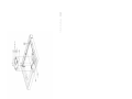
This product is required to comply with the European Union’s Waste
Electrical & Electronic Equipment (WEEE) Directive 2002/96/EC. It is
marked with the following symbol:
Thermo Electron has contracted with one or more recycling/disposal
companies in each EU Member State, and this product should be
disposed of or recycled through them. Further information on Thermo
Electron’s compliance with these Directives, the recyclers in your country,
and information on Thermo Electron products which may assist the
detection of substances subject to the RoHS Directive are available at
www.thermo.com/WEEERoHS.
PDF compression, OCR, web-optimization with CVISION's PdfCompressor
© 2004 Thermo Electron Corporation. All rights reserved.
“Eberline PCM-2” is a registered trade name of Thermo Electron Corporation.
PDF compression, OCR, web-optimization with CVISION's PdfCompressor
Contents
Thermo Electron Corporation
Chapter 1
Introduction...................................................................................1-1
General Description ............................................................. 1-1
Specifications ....................................................................... 1-4
Theory of Operation ............................................................ 1-8
Operational Mode................................................................ 1-8
Test Mode ........................................................................... 1-9
Chapter 2
Installation ....................................................................................2-1
Unpacking ........................................................................... 2-1
Electrical Power Installation ................................................. 2-3
Other Optional Connections ............................................... 2-4
Configuration ...................................................................... 2-4
Quick-Start Instructions ...................................................... 2-5
Chapter 3
Operation .......................................................................................3-1
Normal Operation ............................................................... 3-1
Computer Interface.............................................................. 3-2
Chapter 4
View................................................................................................4-1
Measurement Results ........................................................... 4-1
Transaction Report .............................................................. 4-1
Background Averages ........................................................... 4-1
Day File ............................................................................... 4-1
Detector Performance Data.................................................. 4-2
Hand Probe Readings .......................................................... 4-2
Gross Count Rates ............................................................... 4-2
Chapter 5
Edit ..................................................................................................5-1
Preset All Mode.................................................................... 5-1
Fixed Count Time Mode ..................................................... 5-6
Detector Parameters............................................................. 5-8
Minimum Count Time Mode............................................ 5-10
Detector Parameters........................................................... 5-11
Hand Probe Parameters...................................................... 5-14
Channel Override Parameters............................................. 5-15
Instrument Configuration Parameters ................................ 5-16
Day File Logging................................................................ 5-19
RadNet Parameters ............................................................ 5-20
Sum Zone Setup ................................................................ 5-21
PCM-2 Technical Manual
iii
PDF compression, OCR, web-optimization with CVISION's PdfCompressor
Contents
Chapter 6
Status ..............................................................................................6-1
Overall Monitor Status ........................................................ 6-1
Detector Status .................................................................... 6-1
Log File................................................................................ 6-2
Chapter 7
Calibration .....................................................................................7-1
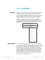
Overview.............................................................................. 7-1
Source Check ....................................................................... 7-1
Background Plateau ............................................................. 7-2
Source Plateau...................................................................... 7-3
Special Considerations ......................................................... 7-4
Efficiencies ........................................................................... 7-6
Shield Factors....................................................................... 7-7
Statistical Variance Test ....................................................... 7-7
False Alarm Test................................................................... 7-7
Calibration Report ............................................................... 7-7
Chapter 8
Utilities...........................................................................................8-1
Detector Download ............................................................. 8-1
Front Panel Test .................................................................. 8-1
Communications Check ...................................................... 8-2
Voice Annunciator Test ....................................................... 8-2
Remote Annunciator Test .................................................... 8-2
Badge Reader Test................................................................ 8-2
Access Gate Check ............................................................... 8-2
Set Clock ............................................................................. 8-2
Edit Colors........................................................................... 8-2
Mask User ID ...................................................................... 8-3
Transfer Files ....................................................................... 8-3
Delete Files .......................................................................... 8-3
Exit to DOS......................................................................... 8-3
Chapter 9
Maintenance .................................................................................9-1
Preventative Maintenance .................................................... 9-1
Switches ............................................................................... 9-2
Decontamination Cleaning .................................................. 9-3
Detector Maintenance.......................................................... 9-3
Quick-Purge Line................................................................. 9-3
Troubleshooting................................................................... 9-5
Chapter 10 Hardware Complement Sheet..................................................10-1
iv
PCM-2 Technical Manual
Thermo Electron Corporation
PDF compression, OCR, web-optimization with CVISION's PdfCompressor
Contents
Chapter 11 Front Panel Board ...................................................................... 11-1
General Description ........................................................... 11-1
Circuit Description ............................................................ 11-1
Keyboard Inputs ................................................................ 11-9
Host Communications Port Configuration ........................ 11-9
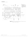
Chapter 12 RS-232 to RS-485 Interface ....................................................... 12-1
General Description ........................................................... 12-1
Theory of Operation .......................................................... 12-1
Special Functions ............................................................... 12-1
RS-232 to RS-485 Interface Parts List................................ 12-2
Chapter 13 Modular Detector Board........................................................... 13-1
General Description ........................................................... 13-1
External Connections......................................................... 13-1
Circuit Description ............................................................ 13-2
Setup and Calibration ........................................................ 13-2
Threshold Values ............................................................... 13-3
Modular Detector Board Parts List .................................... 13-4
Chapter 14 Clock Display Board.................................................................. 14-1
General Description ........................................................... 14-1
Chapter 15 Traffic Light Board .....................................................................15-1
General Description ........................................................... 15-1
Chapter 16 Detectors .....................................................................................16-1
General Description ........................................................... 16-1
Design Configuration ....................................................... 16-2
Maintenance ...................................................................... 16-3
Chapter 17 Hard Disk Drive ..........................................................................17-1
Chapter 18 Swiveling Casters...................................................................... 18-1
Chapter 19 Options ......................................................................................... 19-1
Hand Probe Option ........................................................... 19-1
Hand Probe
Clicker Board..................................................................... 19-3
Voice Annunciator ............................................................. 19-6
Sound Card
Voice Annunciator ............................................................. 19-7
Printer Option ................................................................. 19-14
Wall Mount Remote Annunciator ................................... 19-20
Access Control ................................................................. 19-23
Optional Features............................................................. 19-26
Thermo Electron Corporation
PCM-2 Technical Manual
v
PDF compression, OCR, web-optimization with CVISION's PdfCompressor
Contents
Chapter 20 Standard Parts List .....................................................................20-1
Chapter 21 Recommended Spare Parts ......................................................21-1
Chapter 22 Drawings......................................................................................22-1
Appendix A Statistical Control of Radiological Measurements ..............A-1
Introduction.........................................................................A-1
Basic Measurement Parameters ............................................A-1
Distribution Functions.........................................................A-5
Summary ...........................................................................A-23
Appendix B Procedures ...................................................................................B-1
General Notes ...................................................................... B-1
Required Equipment............................................................ B-1
Setup.................................................................................... B-2
Background Checks ............................................................. B-3
Source Plateaus .................................................................... B-3
Statistical Variance Test ....................................................... B-4
Optional ..............................................................................B-4
Efficiencies and
Shield Factors.......................................................................B-5
Access Gate Test ................................................................. B-6
Appendix C Sigma Factor and RDA Calculators.......................................... C-1
Appendix D PCM-2 Revised Detector Assembly Procedure .....................D-1
P/N 11000A308 ................................................................. D-1
Appendix E PCM-2 Detector High Voltage and Leak Test Procedure..... E-1
P/N 10429A525 .................................................................. E-1
vi
PCM-2 Technical Manual
Thermo Electron Corporation
PDF compression, OCR, web-optimization with CVISION's PdfCompressor
Chapter 1
General Description
Introduction
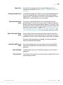
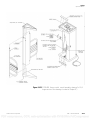
The Eberline PCM-2 is a monitoring instrument that provides rapid and
convenient detection and localization of alpha and beta/ gamma
contamination on personnel. Sixteen gas proportional detectors designed for
rapid replacement or repair provide superior localization of contamination
and background rejection. A contoured array of 34 counting zones, each
with separate alpha and beta/gamma channels, provides data from which the
instrument can determine the presence of both localized and distributed
contamination. In addition, up to 75 sum zones can be defined, each
comprised of 2, 3 or 4 adjacent detectors, for a maximum detection of
contamination that is spread over two or more detectors. (The PCM-2
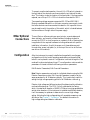
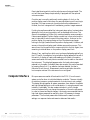
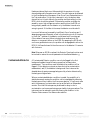
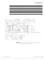
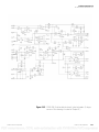
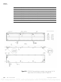
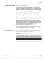
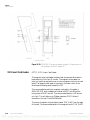
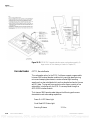
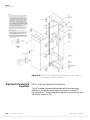
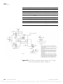
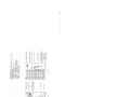
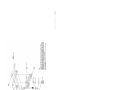
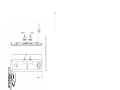
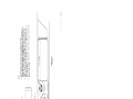
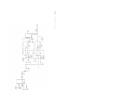
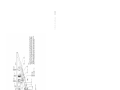
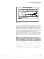
outline drawing is reproduced below in Figure 1-1 and also in Figure 22-1
in Chapter 22: “Drawings”.)
A sum channel is the summation of all 34 detectors into a single counting
channel. With α and ß/ ϒ discrimination, the 34 discrete channels, 75 sum
zones, and sum channel provide a total of 220 measurements per count
cycle. Since a person is measured with two count cycles, there are 440
independent measurements performed per person. The sum channel is
thereby capable of detecting low-level, widely distributed contamination.
Individual detector channels within the PCM-2 are independently
controlled by distributed microprocessors. In addition, a Pentium
class-based single board computer and a large 10.4" LCD panel provide a
user-friendly interface for the system. This enhanced controller also
simplifies calibration and maintenance of the unit and presents test results
to the user in a clear and easily understood graphic format. A full-size
keyboard is stored inside the unit for use during setup, calibration and
troubleshooting. The PCM-2 is also capable of logging measurement data
in any of several formats to a printer or host computer system using RadNet
broadcasts over an Ethernet network.
The PCM-2 features a functionally ergonomic design that maximizes user
body contact with, and minimizes dead areas between, the detectors. A color
VGA LCD panel is used to display information during normal operation as
well as during setup, calibration and maintenance. If contamination is
detected during a measurement cycle, a color graphic image is presented to
indicate contamination locations. The image is one of a user’s body outline
placed in front of the unit’s detector grid, with the alarmed detectors
indicated in red.
Thermo Electron Corporation
PCM-2 Technical Manual
1-1
PDF compression, OCR, web-optimization with CVISION's PdfCompressor
Introduction
General Description
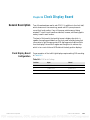
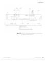
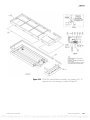
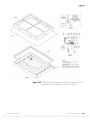
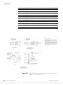
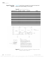
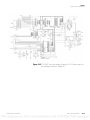
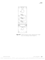
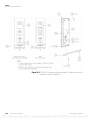
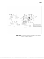
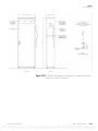
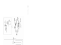
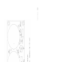
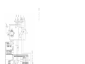
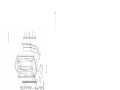
Figure 1-1. 11534-555, PCM-2 outline. (A larger version of this drawing is
located in Chapter 22.)
1-2
PCM-2 Technical Manual
Thermo Electron Corporation
PDF compression, OCR, web-optimization with CVISION's PdfCompressor
Introduction
General Description
Two additional count-down clock / graphic displays provide information
and instructions to help the user assume a correct body position relative to
the detector grid for proper measurement. Red LEDs indicate to the user
any proximity switches that need to be actuated in order to achieve proper
body positioning. During the measurement, the remaining count time (in
seconds) is indicated on the active display. A standard audible annunciator
and an optional voice annunciator provide user prompts to supplement the
visual counting clocks, position indicators and graphic screen.
Input of a user identification (user ID) number and Radiation Work Permit
(RWP) number (if either or both are selected) can be performed from the
20-button touch keypad or an optional magnetic or bar code reader. When
this information is inputted, it is appended to the date- and time-stamped
transaction record for that measurement. The measurement results are
stored on a hard disk drive in the PCM-2. The hard drive is large enough to
accommodate several years’ worth of measurement data. Source check
results and calibration reports are also stored on the hard drive.
The PCM-2 is provided with swiveling casters with immobilization levelers
for improved mobility. This feature allows the unit to be moved easily by
one person, for service access.
In addition, the following optional features are available:
Thermo Electron Corporation
•
Hand-held frisking probe for finer localization of contamination.
•
Voice-prompting capability to enhance the user interface.
•
Printed reports of count results and calibration data.
•
Remote alarm and status display module with wall-mounting
capability.
•
Magnetic or barcode ID badge readers.
•
Polyethylene film dispenser for foot-detector protection and
maintenance.
•
Modular gas bottle enclosure for two Size 1A counting gas cylinders.
•
Network cable and supporting network software for integration of the
PCM-2 onto an RS-485 or Ethernet network
•
Small-hole perforated grid footplate for support of users with high
heels.
PCM-2 Technical Manual
1-3
PDF compression, OCR, web-optimization with CVISION's PdfCompressor
Introduction
Specifications
•
Gas management system for minimization of counting gas usage.
•
Internally mounted, continuously purging spare detectors
•
High-sensitivity screens are available as an option, replacing the heavier
rugged steel detector screens normally provided for rough or high-usage
environments.
The PCM-2 also features networking capability. A central computer
software package which operates on a PC is available for communicating
with the PCM-2 network and archiving counting transactions to disk or
printer. PCM-2 operating parameters can be controlled by the central
computer as well as locally through the keyboard. Local connection of a
printer to each PCM-2 is also supported.
Specifications
Mechanical
Width
36.00 in. (91.44 cm)
Depth
27.00 in. (68.58 cm)
Height
86.50 in. (219.71 cm)
Weight
660 lbs. (300 kg).
Temperature
Operating
From –32 °F to 113 °F (0 °C to 45 °C)
Storage
From –4 °F to 140 °F (–20 °C to 60 °C).
Humidity
Operating
0 to 95% (non-condensing).
Voltages
1-4
PCM-2 Technical Manual
Input
90–132 or 180–264 Vac, 50/60 Hz, 250 W
maximum.
AC Fuse
3.0 Amp slow-blow at 250 Vac.
Thermo Electron Corporation
PDF compression, OCR, web-optimization with CVISION's PdfCompressor
Introduction
Specifications
Display
10.4" VGA color LCD panel, 640 X 480 resolution, 85–264 Vac, 50 / 60
Hz, on/off, brightness, contrast controls, 100,000-hour operation
reliability.
Serial Ports
Host computer port
Selectable between either uLAN and non-uLAN (standard) binary
protocol data format.
1 start bit, 8 data bits, 1 address marker bit (only if uLAN is selected,
otherwise no parity), and 1 stop bit.
RS-232C (standard) or RS-485 (optional).
User selected baud rates of 300, 600, 1200, 2400, 4800, 9600 and
19,200 are available. The default baud rate is 9600.
Card reader port
ASCII data format.
1 start bit, 8 data bits, no parity and 1 stop bit.
RS-232C for Computer Identics bar code reader.
TTL for Xico magnetic card reader.
Baud rate is fixed at 9600.
PCM-2 interface port
Binary protocol data format.
1 start bit, 8 data bits, no parity and 2 stop bits.
RS-232C level.
Baud rate is fixed at 9600.
Thermo Electron Corporation
PCM-2 Technical Manual
1-5
PDF compression, OCR, web-optimization with CVISION's PdfCompressor
Introduction
Specifications
Gas manager communication port
Binary type uLAN protocol data format.
1 start bit, 8 data bits and 1 stop bit.
RS-485 only.
Baud rate is fixed at 19.2K (19,200) baud.
Computer
Minimum Specifications
Pentium-class processor, 300 MHz or faster, with 64 MB RAM or more,
VGA graphics video card, RJ-45 Ethernet connection, 2 serial ports,
1 parallel port.
System Memory
SDRAM SODIMM x 1, Max. 256 MB.
System Chipset
AMD CX 5530.
Watchdog Timer Software Enable/disable 1.6 sec. optional 65 sec.
Expansion Interface
PC/104.
Battery Lithium
3 V/ 196 mAH.
I/O
MIO 1 x EIDE (Ultra DMA33), 1 x floppy disk drive, 1 x keyboard,
1 x mouse, 1 x RS-232/422/485, 1 x RS-232, 1 x LPT.
Ethernet
Chipset RealTek 8139C.
Interface IEEE 802.3u 100Base-T Fast Ethernet compatible.
Built-in boot ROM in Flash BIOS.
Display
Chipset AMD CX 5530.
Memory size 1-4 MB UMA share memory.
1-6
PCM-2 Technical Manual
Thermo Electron Corporation
PDF compression, OCR, web-optimization with CVISION's PdfCompressor
Introduction
Specifications
Resolution up to 1024 x 768 at 24 bpp non-interlaced CRT.
1024 x 768 at 18 bpp TFT-LCD display (supports 3.3 V-LCD).
LCD Interface 18-bit TTL for TFT-LCD only.
Dimensions (L x W) 145 x 102 mm (5.7" x 4").
Power supply voltage
+5 V ± 5%
Maximum
4 A, +5 V
Typical
1.5 A @ +5 V.
Operating temperature
0°–60° C (32°–140° F).
Operating humidity
0%–90% relative humidity,
non-condensing.
Weight
0.75 kg (weight of total package).
Counting Computers
Intel 7.3 MHz 87C51FA microprocessor with 32 kB EPROM and 256
byte RAM, separate computer controlled thresholds for beta and alpha
pulses, anti-coincidence circuitry to prevent alpha pulses from being
counted in the beta channel.
High Voltage Supply
Microprocessor-based, computer-controlled high-voltage adjustment up to
2500 V, failure-sensing provided.
Detectors
Counting Gas
Thermo Electron Corporation
16 separate gas flow proportional detectors subdivided into 34 counting
zones:
9 large
212 sq in. (1368 sq cm) detectors, split into 3 counting
zones.
4 medium
113 sq in. (728 sq cm) detectors.
3 small
50 sq in. (325 sq cm) detectors.
P-10 (90% argon, 10% methane).
PCM-2 Technical Manual
1-7
PDF compression, OCR, web-optimization with CVISION's PdfCompressor
Introduction
Theory of Operation
Gas Usage
Theory of Operation
Operational Mode
One size 1A P-10 gas cylinder = approximately 24 days @ 200cc / min flow.
Users have reported up to a factor of 10 reduction in gas usage, using the
PCM-2 Gas Manager (see “OPT12, Gas Management” on page 19-57).
Radioactive emissions cause ionization of the counting gas in the detector
chambers. The ions are collected at the detector anode wire causing small
voltage pulses on top of the static high-voltage that is applied to the anode
wire. Through capacitive coupling, the pulses are stripped from the
high-voltage, amplified, and discriminated by pulse height into alpha and
beta gamma channels. The detector microprocessors count the pulses, and
convert the counts to count rates. Count rate information is communicated
to the system controller over an RS-485 bus. The system controller applies
the appropriate algorithms to update background count rates and measure
for contamination.
In its main task loop, the computer program continually updates
background count rates for all detector channels, performs diagnostic
checks, and monitors input devices to determine if a person will be
measured. Numerous I /O devices are used to prompt the user and verify
correct positioning for a contamination measurement. The results of the
measurement are annunciated audibly and visually. The measurement is
principally a qualitative determination (an alarm indicates a high probability
that the person is contaminated; no alarm indicates a high probability of no
contamination present). Notwithstanding, alarm annunciation includes
presentation of quantitative information, i.e., activity levels are stated.
Three counting modes are supported: Preset All, Maximum Sensitivity
(Fixed Count Time), and Minimum Count Time. In each mode, statistical
control of the counting exercise ensures that the performance of the monitor
is optimized for that mode’s key parameters. The alarm set points (all three
modes), RDA (mode 2), and minimum count time (mode 3) are all
computed for each new background measurement. The parameters used
include average background count rate, count time, sigma factor (which
controls false alarm probability), confidence level, RDA and detector
efficiency.
Preset All
1-8
PCM-2 Technical Manual
This mode maintains a fixed confidence level (probability of detection) for
the user-selected RDA and count time. False alarm probability is
maintained at or below a user-prescribed maximum. This mode is best used
when a fixed release limit is established and lower levels of activity are of
negligible concern. This mode is also useful when a fixed count time and
fixed alarm set points are preferred.
Thermo Electron Corporation
PDF compression, OCR, web-optimization with CVISION's PdfCompressor
Introduction
Test Mode
Maximum Sensitivity
This mode is appropriate for ALARA measurements. Using a fixed count
time that is selected by the user, the instrument applies the selected
confidence level to achieve the lowest possible RDA while maintaining a
fixed false alarm probability.
Caution This mode of operation will alarm on very low levels of
contamination. Experience has shown that it is often impossible to verify
alarms in maximum sensitivity mode using a hand-held frisker. For this
reason, this mode of operation is not normally used. ▲
Minimum Count Time
The minimum count time is determined automatically for a fixed false
alarm probability and RDA with its associated confidence level. All
detectors will count for the full count time as determined by the channel
requiring the longest minimum count time.
The PCM-2 setup program recalculates all affected operating parameters
whenever a user-defined variable is changed and gives immediate indication
of the affects of the change. During operation, whenever background levels
increase to the point that the statistical parameters cannot be maintained,
the instrument is taken out of service and a high background alarm is
issued.
Test Mode
Thermo Electron Corporation
Test mode is a collection of menu-driven routines that are used to perform
diagnostics, observe count rate information, edit parameters, perform
source checks, and calibrate the monitor. Routines are selected using a
system of pull-down menus and hot keys. Many of the procedures are
automated, and only requires the user to establish setup parameters. As an
example, the computer generates high-voltage plateaus without any need for
the technician to adjust or measure high voltages or record data. The
computer manages these functions and presents the results in both tabular
and graphical formats.
PCM-2 Technical Manual
1-9
PDF compression, OCR, web-optimization with CVISION's PdfCompressor
Introduction
Test Mode
BLANK PAGE
1-10
PCM-2 Technical Manual
Thermo Electron Corporation
PDF compression, OCR, web-optimization with CVISION's PdfCompressor
Chapter 2
Unpacking
Installation
The PCM-2 is shipped upright packed with protective cardboard and
bagged foam and is wrapped in plastic. The standard shipping configuration
also includes a cardboard “extraneous parts” box that resides on the floor of
the unit. This box contains the unit’s P-10 counting gas bottle regulator,
lifting eyebolts, spare tubing, door and upper cover lock keys, MS-DOS and
PCM-2 boot software disk, and a copy of this technical manual.
For PCM-2s equipped with any options, the associated optional hardware is
installed in the unit, with the exceptions of the hand-frisking probe, printer,
remote annunciator and remote annunciator wall bracket options 1, 3, 4
and 14 respectively. An additional box or boxes will be provided on the
floor of or separately with the PCM-2 for units with these options.
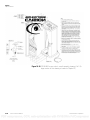
Prior to removal of its shipment packaging, the PCM-2 should be moved to
the location of its ultimate use so as to avoid damaging its exterior surfaces
in transporting. As mentioned, two large eyebolts are provided for overhead
lifting of the unit. These eyebolts install into threaded sockets located in the
ceiling of the unit at the front right and rear left corners (see Figure 1-1).
For overhead lifting, a chain or webbing strap should be attached through
both of these eyebolts to keep the unit upright and to properly distribute the
unit’s load when hoisted.
Caution Use appropriately rated equipment and exercise due safety
precautions when lifting the PCM-2 unit in this overhead fashion. A large
appliance dolly with a retaining strap and incline truck can be used for
moving the PCM-2 on the ground. ▲
Note Avoid rolling a PCM-2 unit equipped with swiveling casters across
uneven surfaces or at rapid rates across any surface. Casters are intended for
quick and easy movement of the unit away from its fixed operating position
(i.e., up against a wall or another unit) to access rear and side doors. The
spring-loaded caster levelers provided with the caster option stop the unit
from being moved over rough or uneven surfaces and should be in their
retracted (up) positions prior to moving the unit. The casters are intended
for use on smooth surfaces only. ▲
Thermo Electron Corporation
PCM-2 Technical Manual
2-1
PDF compression, OCR, web-optimization with CVISION's PdfCompressor
Installation
Unpacking
Counting Gas Installation
The PCM-2 uses gas proportional detectors that require an approximate
total of 200 cc/min of P-10 counting gas for their operation.
Note The optional gas management system reduces the gas usages
significantly. Two gas inputs are provided, for which supply hose feed
through grommets at the rear side columns of the instrument are provided.
The instrument will select one gas source upon powerup and continue to
use that source until its pressure fails, at which time the alternate gas source
will automatically be selected via internal gas-switching electronics. If both
inputs drop below approximately 2 psi, the instrument will cease to
operate. ▲
If portable cylinders are used to supply counting gas, each must be regulated
down to approximately 5 psi and connected to one of the gas inputs. The
standard PCM-2 unit includes one gas bottle pressure regulator located in
the extraneous parts box, as noted above (see “Unpacking” on page 2-1). If
the optional gas bottle enclosure (“OPT9, Gas Bottle Enclosure” on
page 19-53) is ordered, one additional gas pressure regulator is included. If
two counting gas sources are installed, it is important that both regulators be
set to the same pressure so that gas flow will remain constant when the
second cylinder is selected. If the pressure at either input fails, a message will
be displayed on the LCD panel indicating that the gas cylinder needs to be
replaced.
When the instrument is operated from a permanently installed counting gas
manifold, both inputs may be connected to the same 5-psi source. This will
eliminate false “Gas Bottle Empty” messages.
Gas Flow Adjustment
Two flow meters are provided along with a single-needle valve to adjust the
gas flow rate. For normal operation, use the low-range meter to set a flow
rate of approximately 200 cc/minute. When setting up a new instrument or
an instrument that has been disconnected from its gas supply, adjust the
flow to 0.8 liter per minute (800 cc/min) for four hours to purge the
detectors completely.
Note To avoid bursting or damaging the Mylar® entrance windows, do not
exceed 1 liter per minute (1,000 cc/min) at any time. ▲
If replacing a detector, the replacement detector should be purged on the
bench prior to installation or purged in place after installation using the
Quick Detector Purge gas supply hose coil located behind the flow meter
mounting bracket. If the latter method is used for detector purging,
disconnect the red gas supply hose from the subject detector and plug the
quick-purge line in its place. This procedure effectively reroutes the gas flow
2-2
PCM-2 Technical Manual
Thermo Electron Corporation
PDF compression, OCR, web-optimization with CVISION's PdfCompressor
Installation
Electrical Power Installation
from the system’s gas supply harness to the purging detector. Utilization of
this quick-purging hose feature will provide complete purging of a large
PCM-2 detector within approximately 20 minutes at a nominal gas flow
rate of 200 cc / min. Faster purging times can be achieved by increasing the
gas flow rate; however, caution must be exercised to avoid bursting the
detector’s mylar face. A more thorough explanation of the quick-purging
line feature appears in “Quick-Purge Line” on page 9-3.
Each of the sixteen detector chambers is connected to two gas plumbing
harnesses/manifolds, a red gas supply harness and a blue gas exhaust
harness. For faster purging, because the counting gas is heavier than air the
supply hose should always connect to the lowermost gas fittings of vertically
mounted detectors.
If the Hand Probe option (“OPT1, Hand Probe” on page 19-1) is installed,
a third gas-flow meter and a separate rate adjustment needle valve are
provided. This single handheld detector will operate adequately on
5–10 cc/minute of P10 counting gas, regardless of whether a gas manager is
present or not.
For units equipped with Spare Purging Detectors (“OPT15, Spare Purging
Detectors” on page 19-66), you do not need to apply special gas-flow rate
adjustment considerations because these spare detectors are provided with
exhaust gas downstream from the main detectors and are ready to be placed
into use without additional purging.
For units equipped with a Gas Manager (“OPT12, Gas Management” on
page 19-57), refer to Chapter 19: “Options” for detailed system adjustment
direction, because operation of the gas supply / exhaust system is
significantly different from that of a standard unit.
Electrical Power
Installation
Power is brought into the PCM-2 via a four-outlet power strip. Into this
strip are plugged power cords from the unit’s lower electronics enclosure
and options such as a printer or badge reader. The line cord attached to this
power strip may exit the unit either through the lower rear corner of the
cabinet or through the top of the unit near its right-hand side, depending
upon user need. The default configuration for power cord egress is through
the lower rear power inlet plate.
While the PCM-2 is relatively immune to line noise and transients, it is
possible for very large power line spikes to interfere with the instrument.
Avoid connecting the PCM-2 to power circuits shared with large motors or
other inductive loads. If clean line power is not available, a line conditioner
should be installed.
Thermo Electron Corporation
PCM-2 Technical Manual
2-3
PDF compression, OCR, web-optimization with CVISION's PdfCompressor
Installation
Other Optional Connections
To prevent unauthorized operation, the unit’s On /Off switch is placed on
the right side of the electronics enclosure inside the unit behind the side
door. This location is also the location of the fuse holder. If the fuse must be
replaced, use a 3-Amp 1.25 x 0.25 inch slow blow fuse rated for 250 V.
Two operating voltage ranges are supported: 90–132 and 180–264 V.
Moving a recessed slide switch on the main computer power supply inside
the lower electronics enclosure makes this selection. An inspection mirror
may be used to verify the position of this switch, which is located between
the two outlets on the right side of the power supply.
Other Optional
Connections
Configuration
Thermo Electron offers as options a report printer, a remote status and
alarm indicator, and a variety of data interfaces (including wireless) to
connect the PCM-2 to a host computer or a network. Each of these options
is supplied with the required hardware including cables and with specific
installation information. As with the power cord, these cables may exit
through either power inlet plate (i.e., at the top of the unit or at the lower
rear corner of the cabinet).
After the instrument is properly installed and purged with counting gas,
configuration with the correct operating parameters must be performed
before it can be placed in service. Configuration is soft-set through the Test
mode edit routines via keyboard input. The configuration routines and the
parameters of interest include the following minimum parameters:
Edit Detector Parameters / Edit Override Parameters
Note Detector parameters can be set for individual detectors using the Edit
Detector Parameters routine. Edit Override Parameters is used to set the
same parameters for all 34 detectors globally. This is particularly useful for
setting the high-voltage operating points for all 34 detector channels. ▲
Detector high-voltage and efficiencies should be determined by calibration
routines before being set. The PCM-2 is fully calibrated at the factory,
which is located at an elevation of 6,480 ft. Different counting gas densities
exist at other elevations. If the instrument is installed at a different elevation,
it will be necessary to replateau to determine the correct high-voltage
setting. Adjusting the high-voltage setting will necessitate measuring new
efficiencies. See Chapter 7: “Calibration” for detailed information on
high-voltage settings and detector calibration.
2-4
PCM-2 Technical Manual
Thermo Electron Corporation
PDF compression, OCR, web-optimization with CVISION's PdfCompressor
Installation
Quick-Start Instructions
Reliably detectable activity (RDA) levels should be set to the values required
by plant administration. RDA levels can be edited in Detector Parameters,
Override Parameters, or System Parameters.
Edit System Parameters
As noted above, RDA levels can be set for all channels in this screen. If
Mode 2 is being used, this parameter is RDA Upper Limit. Default values
are 5,000 dpm for the beta channels and 900 dpm for the alpha channels.
The RDA confidence should be edited if it is to be other than the default
value of 95%.
The count time (max count time in Mode 3) is set in this screen.
Edit Instrument Parameters
The preferred count rate units (counts per second/cps or counts per
minute/cpm); activity units (dpm, dps, Bq, or nCi); and count mode are set
in this screen. The three counting modes are:
Mode 1
Preset All
Mode 2
Maximum Sensitivity
Mode 3
Minimum Count Time
If reporting or logging of data either locally or over a network installation is
desired, additional parameters will need to be configured in this screen.
See “Instrument Configuration Parameters” on page 5-16 for more
information on configuration parameters.
Quick-Start
Instructions
These instructions are intended to assist the first-time user in setting up
PCM-2 systems. Once this initial setup has been completed, adjustments
may be made to comply with site-specific requirements and policies.
Some familiarity with instruments using gas-proportional radiation
detectors is assumed in these instructions. See the technical sections of this
manual for detailed information regarding the unit and its operation.
Thermo Electron Corporation
PCM-2 Technical Manual
2-5
PDF compression, OCR, web-optimization with CVISION's PdfCompressor
Installation
Quick-Start Instructions
Power Connections
The PCM-2 may be operated from either 90–132 V or 180–264 V,
50/60 Hz. A slide switch located on the computer power supply inside the
electronics enclosure makes voltage range selection. Power is brought in via
a line cord attached to the outlet strip located inside the unit.
1. Remove either of the two cover plates located on the top of the unit
and at the lower rear corner and route this cord out to a convenient
power receptacle.
2. Ensure that the switch on the power strip is turned on.
3. Turn on the unit by actuating the power switch on the side of the
electronics enclosure.
Normal operation is indicated by fan noise from the computer power
supply. Within a few seconds, the disk drive will also begin to operate, lights
on the detector boards will flash, and text will appear on the LCD panel.
Counting Gas Supply
Two gas-inlet hoses exit from the lower right corner of the electronics
enclosure. Each of these should be connected to a supply of P-10 gas (10%
methane, 90% argon) at a regulated pressure of 5 psi. Ensure that both gas
supplies are regulated to the same pressure so that flow rates will not change
when the alternate source is selected. If desired, both inlets may be
connected to the same gas source with a T fitting.
Adjust the gas control to obtain a flow of 800 cc / minute as indicated by the
second flow meter. Maintain this rate for about 4 hours minimum to ensure
that the detectors are fully purged, then decrease flow rate to 200 cc /minute
as indicated by the first flow meter. If the hand probe option is installed, a
third flow meter is provided; purge this probe at 25 cc /minute for
1–2 hours, then decrease its flow to 5–10 cc / minute for normal operation.
Note The flow indication may require 2 to 3 minutes to stabilize. Do not
permit the flow rate to exceed 1000 cc / min at any time. ▲
If a gas manager is installed, see “Gas Management” on page 19-57 for gas
adjustment instructions.
2-6
PCM-2 Technical Manual
Thermo Electron Corporation
PDF compression, OCR, web-optimization with CVISION's PdfCompressor
Installation
Quick-Start Instructions
Accessing the Computer
Either the front panel keypad or the main computer keyboard may be used
to control the instrument; however, for calibration we suggest deploying the
larger keyboard next to the LCD panel.
1. To access the computer’s Main menu, press Escape, and type the
high-level system password (default value = 9999) followed by Enter.
2. Using the four arrow keys, select the Override Parameters screen,
located under Edit on the Main menu. Press Enter to open this
screen.
3. Enter a typical high-voltage setting for gas-proportional detectors
operating at your altitude, followed by Enter.
4. Press Escape to leave this screen and store the new voltage setting.
5. Use the arrow keys to select the Background Averages screen under
the Main menu’s Data heading.
Background count rates for all detectors will be displayed within 1–2
minutes and are updated regularly. Once these values have stabilized, the
unit is ready for calibration and you may reduce gas flows as described
above.
Before proceeding, use the arrow keys, Enter, and Escape to navigate
through the various menus and submenus of the PCM-2 program. Examine
each screen and learn where various functions are located. Refer to
appropriate sections in this technical manual for explanations of anything
that is unclear.
Detector Voltage
Selection
Two high-voltage plateau programs are provided. We recommend running
both before the instrument is put into service. Both are selected from the
Calibration menu.
Due to the large number of detectors on the PCM-2, it is not practical to
run a full voltage plateau on each. The Background Plateau routine uses
natural background radiation as a calibration source and can run all
detectors at the same time. This test should be run over a wide range of
voltages (typically 1400–1900 V), using long count times (at least 300
seconds per voltage). Once the test has started, no operator intervention is
required; we therefore advise running this plateau overnight.
Thermo Electron Corporation
PCM-2 Technical Manual
2-7
PDF compression, OCR, web-optimization with CVISION's PdfCompressor
Installation
Quick-Start Instructions
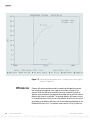
Once the background measurements have been completed, a Plateau screen
is available for each detector. Page through these displays and verify that all
detectors have similar voltage curves. This verifies that all detector channels
have an adequate supply of counting gas and also indicates any problems
involving detector channel–high-voltage failure or broken anode wires.
Note Note the voltage range over which alpha background rates begin to
increase. Use the left and right arrow keys to move the vertical cursor line
and note that the exact count rates displayed at the bottom of the screen are
displayed for each voltage. Best results are obtained at a voltage slightly
below the point at which alpha background rates begin to increase. ▲
The Source Plateau program determines the response of any one detector to
alpha and beta sources. Select starting and ending voltages that bracket the
operating point determined from the Background Plateau results and count
times appropriate to the sources to be used. If large sources are available, it
should not be necessary to correct for background rates. If a Background
Plateau has already been run using the same voltage increments and
covering a range that matches the source plateau high-voltage range,
background corrections may be applied. Both alpha and beta source
plateaus should be run to obtain a full set of results. It is appropriate to run
a high-voltage plateau on three detector channels to determine the optimum
voltage for all channels.
Once an operating voltage has been determined, enter it through the
Override Parameters screen to set all detectors to this value. Individual
detector voltages may be adjusted through the Detector Parameters screen
or the View Plateau display for that channel. Return to the Background
Averages screen and verify that all detectors give reasonable count rates at
the selected voltage. We recommend running source plateaus on at least two
detectors to ensure an appropriate selection of operating voltage for the
entire system. Verify similar results for all detectors that are plateaued.
Detector Efficiency
Calibration
Using the Efficiencies command under the Calibration heading, calibrate
each detector with alpha and beta sources of known activities. For this
purpose, 100 cm² plate sources are preferred over smaller coin sources. Use
high-activity sources when possible because they provide accurate results
with short count times.
Note The isotopes used for calibration should have similar energies to those
isotopes that will be measured during normal operation. ▲
2-8
PCM-2 Technical Manual
Thermo Electron Corporation
PDF compression, OCR, web-optimization with CVISION's PdfCompressor
Installation
Quick-Start Instructions
Enter the activities of the sources to be used. (The instrument will correct
for source decay if given an initial calibration date and the isotope half-life).
Follow the instructions displayed to select a detector, position the source on
that detector, and begin the count.
After you have a satisfactory efficiency measurement, store that value and
move the source to the next detector. After all detectors are calibrated with
one source (alpha or beta), repeat the procedure with the other after
selecting the correct channel type.
Shield Factors
In this procedure, background rates are measured first for all detectors with
the instrument unoccupied and then with a person in measurement
position. The ratios obtained are used to correct for background shielding
effects when a user is in position. Follow the instructions displayed; count
times of at least 100 seconds are recommended to obtain accurate data at
normal background levels.
Selecting Parameters
Edit the Instrument Parameters screen to specify the desired counting mode
(Preset All, Fixed Time, or Max. Sensitivity).
Select other appropriate settings on this screen, such as Enabling / Disabling
Radon Compensation or Alpha Sum Zone Alarms.
RDA levels, count times, etc., may be entered through the System
Parameters screen.
All changes made will be saved on the instrument’s disk and remain in effect
until replaced.
Response Check
Tuning the PCM-2
Thermo Electron Corporation
Before attempting any measurements, place the PCM-2 in operating mode
and allow it to accumulate background count data for several minutes.
Next, select the Source Check function from the Calibration menu. Allow
the instrument to make several measurements with no source present and
verify that few (preferably zero) false alarms occur. Use a source to
determine that each detector responds adequately. If the results obtained are
acceptable, the unit is ready for service.
When the PCM-2 is set up, it may be desirable to fine-tune detector and
instrument parameters for optimum performance. The important fact to
remember when performing such adjustments is that changes that help
PCM-2 Technical Manual
2-9
PDF compression, OCR, web-optimization with CVISION's PdfCompressor
Installation
Quick-Start Instructions
reduce count times and eliminate false alarms may also reduce the unit’s
sensitivity to genuine contamination. All changes should be carefully
evaluated to insure that overall performance remains acceptable.
Problem Detectors
Regardless of how the unit is set up, there will always be one detector that,
due to high background or low efficiency, requires longer count times or
provides lower sensitivity than the others. A typical example is the detector
located under the foot platform: it is mounted horizontally, making it more
sensitive to cosmic radiation; its efficiency is reduced by the heavy metal
grid in front of it; and it may also be shielded by plastic film installed to
protect it from dirt. These factors combine to make this the least sensitive
detector in the PCM-2, particularly for alpha radiation. In order to detect a
specific amount of contamination, basic physics dictates that this detector
will require a longer count time.
To determine which detectors are the limiting factors, select the Detector
Performance screen from the Data menu. This display sorts detectors by
performance, with the worst at the head of the list. If the problem detectors
are significantly worse than the rest, it may be worth (for example)
increasing RDAs in exchange for shorter count times.
Attempting to balance all of the detectors to equal backgrounds or
efficiencies is not required or recommended; computations are performed
independently for each detector to obtain maximum sensitivity in the
shortest possible count time. Excessive changes to individual detector
parameters usually results in unnecessary complication with little or no real
change in performance. Detectors that are not causing significant problems
should be left alone.
Detector Parameters
Individual detectors may be adjusted through the Detector Parameter screen
under the Edit menu. Remember that any subsequent entries made through
the System Parameter or Override Parameter screens will overwrite the
changes made to individual detectors.
The need to modify detector parameters is most frequently motivated by a
detector which demands excessive count times due to high background or
low efficiency. The most direct approach to this problem is to raise the RDA
levels for that particular detector, accepting lower sensitivity in exchange for
more practical count times. This assumes that administrative policy does
not preclude such changes.
If both alpha and beta backgrounds for one detector are elevated, another
useful tactic is to reduce that detector’s operating voltage by 10–20 V. If
beta counts are normal but alphas are too high, the alpha threshold level
2-10
PCM-2 Technical Manual
Thermo Electron Corporation
PDF compression, OCR, web-optimization with CVISION's PdfCompressor
Installation
Quick-Start Instructions
may be increased by as much as 10%, which will move some of the excess
alpha counts into the beta channel. Increasing the beta threshold will
similarly cause some very low-energy particles and extraneous noise to be
completely ignored. Large changes to these parameters will also impact
detector efficiency and may therefore be somewhat self-defeating. Changes
to threshold settings should be accompanied by a replateau of the affected
detector.
In rare instances, a detector with acceptable counting performance may
trigger sensitivity failures due to high or low backgrounds. This is normally
caused by the presence of radiation or shielding which affects one detector
more than the others. If moving or reorienting the unit is not acceptable,
the detector’s geometry factor may be changed. This parameter is used only
by the channel sensitivity test and will not change any test results.
Background rates are simply multiplied by the geometry factor before being
used by the sensitivity test.
Sensitivity failures can be caused by greater fluctuations in ambient
background than are allowed by the alpha or beta sensitivity factors. In such
cases of environmentally induced failures, the symptoms are not due to
poor detector performance. Greater tolerance for background fluctuations is
attained by reducing the sensitivity factors in the System Parameters screen
under the Edit menu.
Gas Flow Adjustment
If several detectors exhibit low background counts, the counting gas flow
rate may be inadequate. Increase the gas flow until acceptable backgrounds
are obtained. There may be considerable lag time between increasing the
flow rate and observing a resultant increase in count rate. The amount of lag
time will depend on the degree of counting gas starvation and the final flow
rate setting.
Living With Radon
Two options are provided to reduce the number of false alarms caused by
radon gas which attaches to clothing. Both may be enabled or disabled from
the Instrument Parameters screen located under the Edit menu.
The first approach is to enable the radon compensation feature. This uses a
proprietary computational algorithm which attempts to recognize the radon
signature by comparing alpha and beta count rates from each detector. The
second and more direct approach is to disable alpha channel sum zone
alarms since this is the most frequent alarm pattern caused by radon
contamination. Sum zone alarms are disabled by raising the sum zone RDA
high enough so that single-channel alarms will always occur before a sum
Thermo Electron Corporation
PCM-2 Technical Manual
2-11
PDF compression, OCR, web-optimization with CVISION's PdfCompressor
Installation
Quick-Start Instructions
zone alarm will occur. This is accomplished when sum zone RDAs are at
least twice the single-channel RDA (or the maximum RDA, if the
instrument is operated in Mode 2).
The radon compensation algorithm uses count information from both alpha
and beta detector channels and operates on the assumption that nonnatural
contaminants will be either pure alpha or pure beta emitters. For this
reason, radon compensation should not be enabled when isotopes such as
uranium, which emit both alpha and beta particles, are to be measured.
Software Maintenance
All changes made to instrument and detector parameters, sum zone groups,
etc., are immediately written both to the instrument’s disk and to
nonvolatile memory on the front panel computer board. Whenever the
PCM-2 is powered up, it will first attempt to reload its parameters from the
disk; if the required files are missing, the program will offer to recreate them
using data from the front panel board. The third option is to reinstate the
factory default values and start over from scratch. Before deleting any disk
files, print a calibration report for the PCM-2 to preserve the current
parameters. If the wrong files are accidentally deleted, this will avoid the
need to completely recalibrate the unit.
Restoring Default Values
To force a return to the factory default parameters, it is necessary to delete
the modified files from disk. Select the Exit to DOS function from the
Utilities menu to stop the PCM-2’s program and obtain access to DOS (the
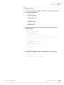
disk operating system). Type the command “Delete xx.dat” (followed by
pressing Enter) where “xx” is one of the following file names:
PCM2SYS
This data file contains instrument and system
parameters, user-set passwords, etc. Deleting this file
will cause all defaults to be reinstated, including those
in the following files.
PCM2DET
Contains the detector parameters.
PCM2ZONE
Contains the sum zone definitions.
PCM2MESG
Contains the default banner-line messages.
Once the desired files have been deleted, press Ctrl+Alt+Del to reboot the
instrument. When the program offers to assign defaults or use the last set of
values, select the defaults. Once this has been done, it is necessary to
completely recalibrate the PCM-2 or key in the correct values since all
efficiencies, voltages and other parameters will have been reset.
2-12
PCM-2 Technical Manual
Thermo Electron Corporation
PDF compression, OCR, web-optimization with CVISION's PdfCompressor
Installation
Quick-Start Instructions
If the user-defined high-level system password is ever lost, another
computer may be used to delete the data files, thus resetting the system to
the default passwords “0000” (low level) and “9999” (high level). It will be
necessary to re-enter all operating parameters.
Software Updates
Update diskettes are shipped without the above data files; however, the
latest set of parameters may be recovered from the front panel board’s
memory with the following procedure:
1. Eject the old diskette from the drive, which is located inside the
electronics enclosure.
2. Insert the new diskette.
3. Reboot the system by pressing the Ctrl+Alt+Del keystroke
combination.
4. When asked which parameters to use, choose to retrieve parameters
from the front panel board, to create a new set of data files on the
diskette.
Thermo Electron Corporation
PCM-2 Technical Manual
2-13
PDF compression, OCR, web-optimization with CVISION's PdfCompressor
Installation
Quick-Start Instructions
BLANK PAGE
2-14
PCM-2 Technical Manual
Thermo Electron Corporation
PDF compression, OCR, web-optimization with CVISION's PdfCompressor
Chapter 3
Normal Operation
Operation
When the PCM-2 is not in use, it continually updates background counts
on all detector channels. As this data is collected, dependent variables such
as count times and alarm set points are recalculated. Approximately two
minutes are required to obtain statistically valid beta backgrounds and up to
twenty minutes of background counts are necessary for accurate alpha
source detection; however, the PCM-2 will begin to operate as soon as the
beta channel backgrounds are valid.
Caution The PCM-2 will not be able to accurately monitor alpha
contamination using the requirements set by the operational parameters
until it has collected a representative background. ▲
If a hand-frisking probe is installed, it may be used during background
update. A display of hand probe readings on the background update screen
results when the hand probe is removed from its cradle on the side of the
instrument. This display disappears when the hand probe is again replaced
into its cradle.
When sufficient beta background data is accumulated, the unit’s traffic
lights, located in the ceiling, change from red to green, indicating that the
unit is ready for measurement. Background counts are halted as soon as a
user steps onto the measuring platform. At this time, the PCM-2’s user
interface becomes active and a measurement cycle begins. If an optional
badge reader is in use, the user may initiate a measurement by scanning the
ID badge either before or after stepping onto the measuring platform.
If the instrument has been set up to accept user ID or radiation work permit
(RWP) numbers, a message is displayed on the LCD panel instructing the
occupant to provide this information. These numbers must be no greater
than nine characters. Keypad entry characters must be numeric, whereas
badge reader characters may be alphanumeric. Depending upon the setup
options selected, entries may be made from the keypad, badge reader (if
installed) or both.
The user is instructed to enter the first counting position as depicted on
position display number one. This requires the user to face into the
detectors and look to the right, toward the active position display. If feet,
hands or body are not in close contact with the instrument, red arrows are
Thermo Electron Corporation
PCM-2 Technical Manual
3-1
PDF compression, OCR, web-optimization with CVISION's PdfCompressor
Operation
Computer Interface
illuminated showing which position switches are not being activated. The
unit will also issue these prompts verbally if equipped with the optional
voice annunciator.
Once the user is correctly positioned, counting begins. A clock on the
position display panel counts down the seconds remaining until counting is
complete. If the user moves out of position before the measurement is
finished, the clock is stopped until a satisfactory position is again assumed.
If mid-cycle results are enabled (an instrument setup option) contamination
detected in the first counting position will be displayed at this time. The
Alarm Acknowledge key (Alarm Ack) must be pressed to resume operation
if alarms are displayed. Position display number two is then active, and the
user is instructed to enter the second counting position. As shown on the
position display, this requires facing out from the detectors and again
looking to the right (toward the active position display panel). As before, red
arrows on the position display panel indicate open position sensors. This
second count cycle is performed in a manner similar to the first. Again, time
remaining is counted down on the position display panel clock.
Alarms, if any, resulting from both count cycles are displayed graphically on
the LCD panel. An example of a typical alarm display appears at the end of
this section. A display of hand probe readings on the alarm information
screen results when the hand probe is removed from its cradle on the side of
the instrument. This display disappears when the hand probe is again
replaced into its cradle. An audible alarm also sounds; this may be canceled
by pressing Alarm Ack. If no radiation has been detected, the user is
instructed to exit the unit. Measurement results are printed or stored for
host computer retrieval if the instrument is so configured.
Computer Interface
3-2
PCM-2 Technical Manual
Microprocessors are used at all levels within the PCM-2, from the main
system controller down to individual detector modules. There are virtually
no switches, jumpers or potentiometers for the technician to set or adjust.
This design brings together all system parameters, from detector thresholds
and high-voltage settings to count mode selection, in a single powerful user
interface. Unavoidably, this also creates a situation in which a single
incorrect keyboard entry can change the operation of the entire instrument.
In order to prevent accidental changes, it is strongly recommended that the
high-level system password be used only when it is necessary to change
parameters. The low-level password should be used to examine current
settings, run response checks and examine status and test results.
Thermo Electron Corporation
PDF compression, OCR, web-optimization with CVISION's PdfCompressor
Operation
Computer Interface
This chapter contains detailed descriptions of the menus and parameters
that may be accessed from the front panel and the mechanics of viewing and
changing them. Detailed explanations of the significance and uses of these
parameters are provided in Chapter 5: “Edit”.
Accessing the Computer
The PCM-2 is controlled by a single board computer that performs all
necessary calculations and also provides the graphical user interface. This
computer may be accessed from either the front panel keypad or the
full-size keyboard stowed inside the instrument. Most functions are
supported by the keypad. The keyboard should be used for instrument
setup and testing because some operations require the use of keys not
available on the front panel.
When any Escape key is pressed, the system requests a password. The
system supports low- and high-level passwords corresponding to the two
available access modes; the password entered determines which mode is
selected. Default values for these passwords are “0000” and “9999,”
respectively. These values may be changed to user-selected four-digit values;
however, the defaults are reinstated if the PCM-2’s parameter files are
re-initialized to their default values.
The currently active item within a menu or screen is highlighted in color.
Other items are selected by using the arrow keys. If the active item is one
with a limited number of possible values such as Count mode or activity
units, Enter, F2, or the arrow keys are used to cycle through the list of
options. Numeric values may be are typed in, followed Enter.
Pressing Escape returns the user to the next higher level menu. From the
Main menu bar, Escape returns the unit to operating mode.
Main System Menu
Thermo Electron Corporation
Upon entering Test mode, a horizontal menu bar is displayed containing
five main headings:
View
Access to background and measurement data.
Edit
Submenus containing parameters and system
configuration options.
Status
System status information.
Calibration
Routines needed to calibrate and verify PCM-2
operation.
Utilities
Routines used to set up and check the PCM-2’s
computer hardware.
PCM-2 Technical Manual
3-3
PDF compression, OCR, web-optimization with CVISION's PdfCompressor
Operation
Computer Interface
These headings may be selected by using the left and right arrow keys or by
typing the highlighted capital letter in the heading name. Pressing Enter or
the down arrow key causes the available functions under the current heading
to be displayed. Items from submenus are selected by pressing Enter or by
typing the highlighted capital letter. The Escape key is used at any time to
exit the present display screen.
Refer to chapters 4 through 8 for detailed operational information on each
of the five major Main menu headings and their submenus.
3-4
PCM-2 Technical Manual
Thermo Electron Corporation
PDF compression, OCR, web-optimization with CVISION's PdfCompressor
Chapter 4
Measurement Results
Transaction Report
Background Averages
Day File
Thermo Electron Corporation
View
A color-coded diagram of the PCM-2 detector array is shown. Detectors
that were in the normal state (at the time of the last measurement) are
indicated in green. Inactive detectors are indicated by white with
out-of-service (failed) detectors shown in blue. Individual-channel alarms
are indicated by bright red; half-tone red indicates sum-zone alarms, and the
sum channel is crosshatched in red if it posted an alarm in the last
measurement. Numerical count data are shown for one detector that is
identified by a flashing cursor. The cursor will automatically be placed on
the alarmed detector that sensed the highest level of activity. The arrow keys
can be used to reposition the cursor over any other detectors. The count
data shown will correspond to the detector channel that is currently
highlighted.
Selecting this item causes a report to be generated from the results of the last
measurement cycle. The report is displayed on the video monitor, and
hardcopy may be produced if a printer is available.
Alpha and beta channel background count rates for all active detectors are
displayed. These are the values currently being used by the PCM-2 for
internal calculations, computed with the current weighting factors. Counts
are updated periodically in this display. Count rates are shown in the units
selected in the instrument parameters menu, which is either counts per
second (cps) or counts per minute (cpm). Pressing the F2 key enables or
disables geometry correction of background data. When correction is
applied, the raw count data is multiplied by a detector geometry correction
factor. This permits easy comparisons of count rates from detectors of
differing sizes.
The user may view the current day files for transactions, status, changes, and
source check results. Day files are explained in detail in “Day File Logging”
on page 5-19.
PCM-2 Technical Manual
4-1
PDF compression, OCR, web-optimization with CVISION's PdfCompressor
View
Detector Performance Data
Detector Performance
Data
Hand Probe Readings
Gross Count Rates
4-2
PCM-2 Technical Manual
Depending upon system operating mode, this screen shows either count
times or RDA values calculated for each detector channel at the present
background levels and operating parameters. The display is sorted from
highest (worst) to lowest (best) to provide a quick assessment of the range of
values and to identify which detectors are most likely to cause problems if
background levels increase.
Stored background and current real-time count rates are shown for the
optional hand-frisking probe (if installed). Background data is accumulated
whenever the probe is in its holder; net count rates are therefore displayed
only when the probe is in use. The hand probe alarm set points for the alpha
and beta channels are also displayed.
The last count rate from each detector channel is shown, without any
averaging or weighting factors applied. This screen is particularly useful for
observing the response of detectors to a source.
Thermo Electron Corporation
PDF compression, OCR, web-optimization with CVISION's PdfCompressor
Chapter 5
Edit
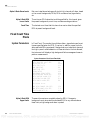
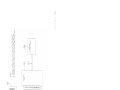
PCM-2 - VERSION V1.9
View
Edit
Status
Calibration
Utilities
Detector Parameters
Hand Probe Parameters
Override Parameters
System Parameters
Instrument Setup Parameters
RadNet Parameters
Sum Zone Setup
Banner Messages
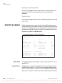
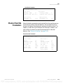
Preset All Mode
Preset All Mode
System Parameters
Thermo Electron Corporation
In Preset All count mode, the alpha and beta RDAs, confidence factor,
sigma factors and count time are specified when the PCM-2 is set up. If
background count rates are (or become) too high, it is not possible to detect
sources of the specified activities (the RDAs) in the time allowed using the
chosen confidence and sigma factors; when this happens, the instrument
displays a high background failure message and ceases to perform
measurements.
PCM-2 Technical Manual
5-1
PDF compression, OCR, web-optimization with CVISION's PdfCompressor
Edit
Preset All Mode
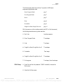
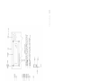
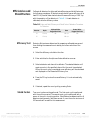
System Parameters–Preset All Mode
ALPHA RDA (DPS):
BETA RDA (DPS):
ALPHA SENSITIVITY:
BETA SENSITIVITY:
RDA CONFIDENCE:
COUNT TIME (SEC):
SIGMA FACTOR:
BACKGROUND SIGMA FACTOR:
ALPHA SUM ZONE ALARM (DPS):
BETA SUM ZONE ALARM (DPS):
ALPHA SUM CH ALARM (DPS):
BETA SUM CH ALARM (DPS):
83.3
417
0.10
0.50
95%
1.00
4.00
4.00
23.3
117
83.3
500
Calculated Values
ALPHA RDA LOWER LIMIT (DPS):
BETA RDA LOWER LIMIT (DPS):
FALSE ALARM RATE (%):
MIN COUNT TIME (SEC):
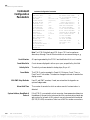
Alpha & Beta RDAs
Alpha & Beta Sensitivities
2.56
17.9
0.19
0.62
These are the RDAs (reliably detectable activities) used to compute alarm
set points for the alpha and beta channels. Values entered are copied to all
alpha and beta detector channels; individual channel RDAs may later be
changed in the Detector Parameters screen.
A ratio above and below the mean of background counts beyond which a
single detector’s background is determined to be indicative of a detector
failure. The default value is 0.5 for the beta channels, meaning that a
detector with more than twice or less than half as many counts as the system
average is considered suspect.
Note Because the size, location and orientation of a detector affect its
background counts, each detector has a geometry factor that is used to
compensate for these variables. Due to the inherently lower background
count rates, the default alpha sensitivity factor is 0.10, allowing an
acceptable range in count rates from 0.1 to 10 times the average. ▲
RDA Confidence
Count Time
5-2
PCM-2 Technical Manual
The probability of detecting contamination of the specified RDA. Possible
values are 50%, 75%, 90%, 95%, 99% and 99.9%. See Appendix A:
“Statistical Control of Radiological Measurements” for a detailed discussion
of this parameter.
The time (in seconds) for which all channels of the PCM-2 will count.
Thermo Electron Corporation
PDF compression, OCR, web-optimization with CVISION's PdfCompressor
Edit
Preset All Mode
Sigma Factor
A multiplier of the background count rate standard deviation that
influences the false alarm rate. See Appendix C: “Sigma Factor and RDA
Calculators”.
Background Sigma Factor
If a background update count differs from the stored average background
rate by the standard deviation value entered, the new rate immediately
replaces the old. If the detectors on which this occurs alarmed on the last
measurement, they are assumed to be contaminated.
Alpha & Beta Sum Zone
Alarm
A sum zone is a user-defined group of two to four detectors that are
grouped together to enhance the monitor’s ability to detect contamination
spread over an area shared by several adjacent detectors. The alpha or beta
sum zone alarm set point defines the activity required within the sum zone
area before a sum zone alarm is triggered. (See “Alpha & Beta Sum Zone
Alarm” on page 5-3, “Alpha & Beta Sum Zone Alarm” on page 5-7, and
“Sum Zone Setup” on page 5-21 for more information about sum zones.)
Alpha & Beta Sum Channel
Alarm
A sum channel is a sum zone consisting of every channel in the monitor.
The alpha or beta sum channel alarm set point is the activity that must be
present within the entire monitor before the sum channel alarm is triggered.
Whenever the above parameters are changed, the following dependent
values are recalculated and displayed.
Alpha & Beta RDA Lower
Limits
At the current background count rates, these limits are the lowest RDA
values which are attainable using the specified count time and statistical
parameters.
False Alarm Rate
The percentage of users who will see false alarms given the current set of
parameters.
Min Count Time
Thermo Electron Corporation
The shortest count time that can be used to detect the specified RDA at the
present background levels.
PCM-2 Technical Manual
5-3
PDF compression, OCR, web-optimization with CVISION's PdfCompressor
Edit
Preset All Mode
Detector Parameters
Detector parameters are normally set via the Override Parameters screen.
Values entered from that screen are written to all detectors; any entries made
previously to a single detector are lost. Parameters for a single channel are
examined or adjusted through the Detector Parameters screen by using the
arrow keys to select the desired detector.
Detector #0 Parameters–Preset All Mode
HIGH VOLTAGE (VOLTS): 1600
GEOMETRY FACTOR:
1.00
Alpha Channel
ACTIVE:
THRESHOLD (% MAX):
EFFICIENCY (%):
RDA (DPS):
HI FAIL (CPS):
LO FAIL (CPS):
WEIGHT FACTOR:
Yes
45
22.0
16.7
100000
0.00
50.0
ACTIVE:
THRESHOLD (% MAX):
EFFICIENCY (%):
RDA (DPS):
HI FAIL (CPS):
LO FAIL (CPS):
WEIGHT FACTOR:
SHIELD FACTOR:
Calculated Values
Calculated Values
BACKGROUND (CPS)
0.00
ALARM LEVEL (NCPS):
1.00
RDA LOWER LIMIT (DPS): 1.00
COUNT TIME (SEC):
1.00
BACKGROUND (CPS):
ALARM LEVEL (NCPS):
RDA LOWER LIMIT (DPS):
COUNT TIME (SEC):
Yes
5
22.0
83.3
100000
0.00
10.0
1.00
0.00
1.00
1.00
1.00
High Voltage
The detector voltage may be adjusted in steps of approximately 10 V, not to
exceed 1750 V, when using P-10 counting gas.
Geometry Factor
Background count rates are multiplied by this factor before being used to
test for detector sensitivity. This converts the detector’s average background
count rates into count rate per unit area in order to compensate for
difference in detector size. It is used only for channel sensitivity test
calculations. All detector sizes are referenced to one-third of a full-size triple
detector. As an example, the default geometry factor for channel 0 is always
1.0.
Alpha & Beta Channels
Active
Detectors marked as inactive are not used in any computations. This is done
to keep the instrument operating if one detector fails.
Alpha Threshold
Particles that cause the detector to produce a pulse exceeding this relative
amplitude are counted as alpha particles. Lower amplitude pulses register as
betas. The default alpha threshold of 45% is seldom changed.
Beta Threshold
5-4
Beta Channel
PCM-2 Technical Manual
Particles that produce pulses below this relative amplitude are counted as
either alpha or beta. The default beta threshold of 5% is seldom changed.
Thermo Electron Corporation
PDF compression, OCR, web-optimization with CVISION's PdfCompressor
Edit
Preset All Mode
Alpha & Beta Efficiencies
The fraction of particles (expressed as a percentage) emitted by the source of
interest in all directions (4 π ) that are counted by the detector,
Alpha & Beta RDAs
Contamination of these activity levels is detected with a probability equal to
the system RDA confidence level.
Alpha & Beta High Fail
Channels which show background levels above these limits will be
considered too noisy or contaminated to use, and will remove the
instrument from service.
Alpha & Beta Low Fail
Channels with backgrounds below these levels are assumed to have failed.
The instrument will not operate if this occurs.
Alpha & Beta Weight Factors
These parameters control the speed with which the computed average
background rates follow changes in actual background count rates. The
weight factors smooth statistical fluctuations in background measurements
by synthesizing an exponential moving average. Increasing the weighting
factor will enhance the smoothing function at the expense of extending the
time constant associated with recognizing step changes in the real average
background count rate. The formula for computing the weighted average
background count rate is
Rbkg =
where
( Rold × WF ) + Rnew
WF + 1
Rbkg= the new computed average background count rate,
Rold= the previous computed average background count rate,
WF= weight factor, and
Rnew= the most recently measured (real) background count rate,
measured in a single count interval.
Beta Shield Factor
When the instrument is occupied, some detectors are shielded from local
radiation sources that account for part of the observed background. The
shield factor is defined as background while occupied divided by background
while unoccupied.
Note Alpha channel shield factors are always equal to 1. ▲
The following values are displayed but may not be edited:
Alpha & Beta Backgrounds
Thermo Electron Corporation
Current background count rates for this channel.
PCM-2 Technical Manual
5-5
PDF compression, OCR, web-optimization with CVISION's PdfCompressor
Edit
Fixed Count Time Mode
Alpha & Beta Alarm Levels
Alpha & Beta RDA
Lower Limits
Count Time
Net count rates (above background) at which this channel will alarm, based
on the current backgrounds, RDAs, RDA confidence level, sigma factor,
etc.
The minimum RDA values that could be specified for this channel, given
the present backgrounds, count time, confidence and sigma factors.
The shortest count time that this channel can use to detect the specified
RDA at present background levels.
Fixed Count Time
Mode
System Parameters
In Fixed Count Time mode, the confidence factor, sigma factors and count
time are specified when the PCM-2 is set up. In addition, upper limits for
alpha and beta RDAs are entered. If background count rates are (or become)
too high to permit reliable detection of these activities in the time allowed,
the instrument will display a high background failure message and cease to
perform measurements.
System Parameters–Fixed Count Time Mode
ALPHA RDA UPPER LIMIT (DPS):
25.0
BETA RDA UPPER LIMIT (DPS):
150
ALPHA SENSITIVITY:
0.050
BETA SENSITIVITY:
0.10
RDA CONFIDENCE:
95%
COUNT TIME (SEC):
1.00
SIGMA FACTOR:
4.00
BACKGROUND SIGMA FACTOR:
4.00
ALPHA SUM ZONE ALARM (DPS):
23.3
BETA SUM ZONE ALARM (DPS):
117
ALPHA SUM CH ALARM (DPS):
83.3
BETA SUM CH ALARM (DPS):
500
Calculated Values
MAX ALPHA CHANNEL RDA (DPS):
MAX BETA CHANNEL RDA (DPS):
FALSE ALARM RATE (%):
Alpha & Beta RDA
Upper Limits
5-6
PCM-2 Technical Manual
2.56
17.9
0.19
These are the maximum acceptable values for RDA. If changes in
background count rates raise the calculated RDA for any channels above
these limits, a high background alarm is posted.
Thermo Electron Corporation
PDF compression, OCR, web-optimization with CVISION's PdfCompressor
Edit
Fixed Count Time Mode
Alpha & Beta Sensitivities
A ratio above and below the mean of background counts, beyond which a
single detector’s background is determined to be indicative of a detector
failure. The default value is 0.5 for the beta channels, meaning that a
detector with more than twice or less than half as many counts as the system
average is considered suspect.
Note Because the size, location and orientation of a detector affect its
background counts, each detector has a geometry factor that is used to
compensate for these variables. Due to the inherently lower background
count rates, the default alpha sensitivity factor is 0.10, allowing an
acceptable range in count rates from 0.1 to 10 times the average. ▲
RDA Confidence
Count Time
Sigma Factor
The probability of detecting contamination of the specified RDA. Possible
values are 50%, 75%, 90%, 95%, 99% and 99.9%. See Appendix A:
“Statistical Control of Radiological Measurements” for a detailed discussion
of this parameter.
The time in seconds for which all channels of the PCM-2 will count.
A multiplier of the background count rate standard deviation that
influences the false alarm rate. (See Appendix A: “Statistical Control of
Radiological Measurements”.)
Background Sigma Factor
If a background update count differs from the stored average background
rate by this many standard deviations, the new rate will immediately replace
the old. If the detectors on which this occurs alarmed on the last
measurement, they are assumed to be contaminated.
Alpha & Beta
Sum Zone Alarm
A sum zone is a user-defined group of two to four detectors that are
grouped together to enhance the monitor's ability to detect contamination
spread over an area shared by several adjacent detectors. The alpha or beta
sum zone alarm set point defines the activity required within the sum zone
area before a sum zone alarm is triggered. (See “Sum Zone Setup” on
page 5-21 for more information on sum zones.)
Alpha & Beta Sum Channel
Alarm
A sum channel is a sum zone consisting of every channel in the monitor.
The alpha or beta sum channel alarm set point is the activity which must be
present within the entire monitor before the sum channel alarm is triggered.
Whenever the above parameters are changed, the following dependent
values are recalculated and displayed:
Thermo Electron Corporation
PCM-2 Technical Manual
5-7
PDF compression, OCR, web-optimization with CVISION's PdfCompressor
Edit
Detector Parameters
Max Alpha & Beta Channel RDA
At the current background count rates, these are the highest RDA for any
channel in the PCM-2 with the specified count time and statistical
parameters.
False Alarm Rate
This is the percentage of users who will see false alarms given the current set
of parameters.
Detector Parameters
Detector parameters are normally set via the Override Parameters screen.
Values entered from this screen are written to all detectors; any entries made
previously to a single detector are lost. Parameters for a single channel may
be examined or adjusted through the Detector Parameters screen by using
the arrow keys to select the desired detector.
Detector #0 Parameters—Fixed Count Time Mode
HIGH VOLTAGE (VOLTS): 1600
GEOMETRY FACTOR: 1.00
Alpha Channel
5-8
Beta Channel
ACTIVE:
THRESHOLD (% MAX):
EFFICIENCY (%):
HI FAIL (CPS):
LO FAIL (CPS):
WEIGHT FACTOR:
Yes
4
22.0
100000
0.00
50.0
ACTIVE:
THRESHOLD (% MAX):
EFFICIENCY (%):
HI FAIL (CPS):
LO FAIL (CPS):
WEIGHT FACTOR:
SHIELD FACTOR:
Calculated Values
Calculated Values
BACKGROUND (CPS):
ALARM LEVEL (NCPS):
RDA LEVEL (DPS):
0.00
1.00
1.00
BACKGROUND (CPS):
ALARM LEVEL (NCPS):
RDA LEVEL (DPS):
Yes
5
22.0
100000
0.00
10.0
1.00
0.00
1.00
1.00
High Voltage
The detector voltage may be adjusted in steps of approximately 10 V not to
exceed 1750 V.
Geometry Factor
Background count rates are multiplied by this factor before being used to
test for detector sensitivity. This factor converts average background count
rates into count rates per unit area in order to compensate for differences in
detector size. This factor is used only for channel sensitivity test calculations.
PCM-2 Technical Manual
Thermo Electron Corporation
PDF compression, OCR, web-optimization with CVISION's PdfCompressor
Edit
Detector Parameters
Alpha & Beta Channels
Active
Detectors marked as inactive are not used in any computations. This may
be done to keep the instrument operating if one detector fails.
Alpha Threshold
Particles that cause the detector to produce a pulse exceeding this voltage
are counted as alpha particles. Lower amplitude pulses are registered as
betas.
Beta Threshold
Particles that produce pulses below this amplitude will not be counted as
either alpha or beta.
Alpha & Beta Efficiencies
The ratio of counts per disintegration expressed as a percentage.
Alpha & Beta High Fail
Detectors which show background levels above these limits are considered
too noisy or contaminated to use and will remove the instrument from
service.
Alpha & Beta Low Fail
Detectors with backgrounds below these levels are assumed to have failed.
The instrument will not count if this occurs.
Alpha & Beta Weight Factors
This parameter controls the speed with which the computed average
background rates will follow changes in actual background count rates. The
weight factors smooth statistical fluctuations in background measurements
by synthesizing an exponential moving average. Increasing the weighting
factor will enhance the smoothing function at the expense of extending the
time constant associated with recognizing step changes in the real average
background count rate. The formula for computing the weighted average
background count rate is
Rbkg =
( Rold × WF ) + Rnew
WF + 1
where
Rbkg = the new computed average background count rate,
Rold = the previous computed average background count rate,
WF = weight factor, and
Rnew = the most recently measured (real) background count rate,
measured in a single count interval.
Beta Shield Factor
Thermo Electron Corporation
When the instrument is occupied, some detectors may be shielded from
local radiation sources that account for part of the observed background.
The shield factor is defined as background while occupied divided by
background while unoccupied.
PCM-2 Technical Manual
5-9
PDF compression, OCR, web-optimization with CVISION's PdfCompressor
Edit
Minimum Count Time Mode
Note Alpha channel shield factors are always equal to 1. ▲
The following values are displayed but may not be edited:
Alpha & Beta Backgrounds
The current background count rates for this detector.
Alpha & Beta Alarm Levels
Net count rates (above background) at which this detector will alarm, based
on the current backgrounds, RDAs, RDA confidence level, sigma factor,
etc.
Alpha & Beta RDA Levels
The activity levels that can reliably be detected within the allowed count
time given current background rates and using the specified RDA
confidence level and sigma factor.
Minimum Count Time
Mode
System Parameters
5-10
PCM-2 Technical Manual
In Minimum Count Time mode, the alpha and beta RDAs, confidence
factor, and sigma factors are specified when the PCM-2 is set up. In
addition, a maximum allowable count time is entered. If background count
rates are (or become) too high, it will not be possible to detect sources of the
specified activities (the RDAs) within the specified maximum count time
using the chosen confidence and sigma factors; when this happens, the
instrument will display a high background failure message and cease to
perform measurements until the condition clears.
Thermo Electron Corporation
PDF compression, OCR, web-optimization with CVISION's PdfCompressor
Edit
Detector Parameters
System Parameters—Min Count Time Mode
ALPHA RDA (DPM):
5000
BETA RDA (DPM):
25000
ALPHA SENSITIVITY:
0.050
BETA SENSITIVITY:
0.10
RDA CONFIDENCE:
95%
MAX COUNT TIME (SEC):
60
SIGMA FACTOR:
4.00
BACKGROUND SIGMA FACTOR:
4.00
ALPHA SUM ZONE ALARM (DPM):
1400
BETA SUM ZONE ALARM (DPM):
7000
ALPHA SUM CH ALARM (DPM):
5000
BETA SUM CH ALARM (DPM):
30000
Calculated Values
COUNT TIME (SEC):
FALSE ALARM RATE (%):
Alpha & Beta RDAs
Detector Parameters
1.00
0.16
The reliably detectable activities used to compute alarm set points for the
alpha and beta channels. Values entered here will be copied to all detector
channels. Individual detectors may later be changed.
Detector parameters are normally set via the Override Parameters screen.
Values entered on this screen will be written to all detectors; any entries
made previously to a single detector will be lost. Parameters for a single
channel may be examined or adjusted through the Detector Parameters
screen by using the arrow keys to select the desired detector. (See “Detector
Parameters” on page 2-10.)
Detector #0 Parameters–Min Count Time Mode
HIGH VOLTAGE (VOLTS): 1600
GEOMETRY FACTOR: 1.00
Alpha Channel
ACTIVE:
THRESHOLD (% MAX):
EFFICIENCY (%):
RDA (DPS):
HI FAIL (CPS):
LO FAIL (CPS):
WEIGHT FACTOR:
Thermo Electron Corporation
Beta Channel
Yes
45
22.0
16.7
100000
0.00
50.0
ACTIVE:
Yes
THRESHOLD (% MAX):5
EFFICIENCY (%):
22.0
RDA (DPS):
83.3
HI FAIL (CPS):
100000
LO FAIL (CPS):
0.00
WEIGHT FACTOR:
10.0
SHIELD FACTOR:
1.00
Calculated Values
Calculated Values
BACKGROUND (CPS): 0.00
ALARM LEVEL (NCPS): 1.00
COUNT TIME (SEC): 1.00
BACKGROUND (CPS): 0.00
ALARM LEVEL (NCPS): 1.00
COUNT TIME (SEC): 1.00
PCM-2 Technical Manual
5-11
PDF compression, OCR, web-optimization with CVISION's PdfCompressor
Edit
Detector Parameters
Alpha & Beta Sensitivities
A ratio above and below the mean of background counts beyond which a
single detector’s background is determined to be indicative of a detector
failure. The default value is 0.5, meaning that a detector with more than
twice or less than half as many counts as the system average is considered
suspect. Note that because the size, location and orientation of a detector
affects its background counts, each detector has a geometry factor that is
used to compensate for these variables.
RDA Confidence
The probability of detecting contamination of the specified RDA. Possible
values are 50%, 75%, 90%, 95%, 99%, and 99.9%. See Appendix A:
“Statistical Control of Radiological Measurements”.
Max Count Time
The longest acceptable count time which the PCM-2 may use for
measurements. If increases in background levels require a measurement time
exceeding this value, a high background alarm condition occurs.
Sigma Factor
A multiplier of the average background count rate standard deviation that
influences the false alarm rate. (See Appendix A: “Statistical Control of
Radiological Measurements”.)
Background Sigma Factor
If a background update count differs from the computed average
background rate by this many standard deviations, the new rate will
immediately replace the old. If the detectors on which this occurs alarmed
on the last measurement, they are assumed to be contaminated.
Alpha & Beta
Sum Zone Alarm
A sum zone is a user-defined group of two to four detectors that are grouped
together to enhance the monitor's ability to detect contamination spread
over an area shared by several adjacent detectors. The alpha or beta sum
zone alarm set point defines the activity required within the sum zone area
before a sum zone alarm is triggered. Refer to the upcoming section or sum
zone setup for more information on sum zones.
Alpha & Beta
Sum Channel Alarm
A sum channel is a sum zone consisting of every channel in the monitor.
The alpha or beta sum channel alarm set point is the activity which must be
present within the entire monitor before the sum channel alarm is triggered.
Whenever the above parameters are changed, the following dependent
values are recalculated and displayed:
Count Time
The measurement count time required at present background rates. This is
the longest count time calculated for any detector channel.
5-12
PCM-2 Technical Manual
Thermo Electron Corporation
PDF compression, OCR, web-optimization with CVISION's PdfCompressor
Edit
Detector Parameters
False Alarm Rate
This is the percentage of users who will see false alarms given the current set
of parameters.
High Voltage
The detector voltage may be adjusted in steps of approximately 10 volts.
Geometry Factor
Background count rates are multiplied by this factor before being used to
test for detector sensitivity. This converts average background count rates
into count rate per unit area in order to compensate for differences in
detector size. This is used only for channel sensitivity calculation.
Alpha & Beta
Channels Active
Detectors marked as inactive will not be used in any computations. This
may be done to keep the instrument operating if one detector fails.
Alpha Threshold
Particles that cause the detector to produce a pulse exceeding this voltage
will be counted as alpha particles. Lower amplitudes register as betas.
Beta Threshold
Particles that produce pulses below this amplitude will not be counted as
either alpha or beta.
Alpha & Beta Efficiencies
Alpha & Beta RDAs
The ratio of counts per disintegration expressed as a percentage.
Contamination of this activity level will be detected with a probability equal
to the system RDA confidence level.
Alpha & Beta High Fail
Detectors which show background levels above these limits will be
considered too noisy or contaminated to use and will remove the
instrument from service.
Alpha & Beta Low Fail
Detectors with backgrounds below these levels are assumed to have failed.
The instrument will not count if this occurs.
Alpha & Beta Weight Factors
This parameter controls the speed with which the computed average
background rate will follow changes in actual background count rates. The
weight factors smooth statistical fluctuations in background measurements
by synthesizing an exponential moving average. Increasing the weighting
factor will enhance the smoothing function at the expense of extending the
time constant associated with recognizing step changes in the real average
background count rate. The formula for computing the weighted average
background count rate is
R bkg =
( R old × WF ) + R new
WF + 1
where
Thermo Electron Corporation
PCM-2 Technical Manual
5-13
PDF compression, OCR, web-optimization with CVISION's PdfCompressor
Edit
Hand Probe Parameters
Rbkg= the new computed average background count rate
Rold = the previous computed average background count rate,
WF = weight factor, and
Rnew = the most recently measured (real) background count rate,
measured in a single count interval.
Beta Shield Factor
When the instrument is occupied, some detectors may be shielded from
local radiation sources that account for part of the observed background.
The shield factor is defined as background while occupied divided by
background while unoccupied.
Note Alpha channel shield factors are always equal to 1. ▲
The following values are displayed but may not be edited:
Alpha & Beta Background
The current background count rates for this detector.
Alpha & Beta Alarm Level
Net count rates (above background) at which this detector will alarm based
on the current background, RDA, RDA confidence level, sigma factor, etc.
Alpha & Beta Count Time
The count times calculated for the alpha and beta channels of this detector
given the current RDA, RDA confidence level, sigma factor and
background count rates.
Hand Probe
Parameters
5-14
PCM-2 Technical Manual
If the hand probe option is installed, this screen may be used to set its high
voltage, alpha and beta thresholds, and alpha and beta alarm set points. An
alarm set point may be entered for both the alpha and beta channels. This
set point is expressed in the count rate units selected for the PCM-2, counts
per second (cps) or counts per minute (cpm). In addition, a weighing factor
and a background sigma factor may be entered for both the alpha and beta
channels. These parameters are used in a smoothing algorithm that has been
incorporated for the hand probe readings to allow the user to control the
response time and the step change for the hand probe readings
Thermo Electron Corporation
PDF compression, OCR, web-optimization with CVISION's PdfCompressor
Edit
Channel Override Parameters
Hand Probe Parameters
HIGH VOLTAGE (VOLTS): 1550
Alpha Channel
THRESHOLD (% MAX):
45
ALARM SET POINT (NCPS) 61.6
THRESHOLD (% MAX):
5
ALARM SET POINT (NCPS) 9.50
Measured Value
Measured Value
BACKGROUND (CPS):
Channel Override
Parameters
Beta Channel
0.032
BACKGROUND (CPS):
6.19
Values for detector parameters may be entered from the override screen as
an alternative to editing individual detectors. Entries made here will be
written to all detectors simultaneously, replacing the existing values. This
capability is useful during initial setup of the instrument; however, care
must be taken to preserve any special values required for individual
detectors. (See “Detector Parameters” on page 2-10.)
Channel Override Parameters
HIGH VOLTAGE (VOLTS): 1550
Alpha Channels
ACTIVE:
THRESHOLD (% MAX):
EFFICIENCY (%):
RDA (DPM):
HI FAIL (CPS):
LO FAIL (CPS):
WEIGHT FACTOR:
Thermo Electron Corporation
Beta Channels
Yes
45
22.0
5000
100000
0.00
50.0
ACTIVE:
THRESHOLD (% MAX):
EFFICIENCY (%):
RDA (DPM):
HI FAIL (CPS):
LO FAIL (CPS):
WEIGHT FACTOR:
SHIELD FACTOR:
Yes
5
22.0
25000
100000
0.00
10.0
1.00
PCM-2 Technical Manual
5-15
PDF compression, OCR, web-optimization with CVISION's PdfCompressor
Edit
Instrument Configuration Parameters
Instrument
Configuration
Parameters
Instrument Configuration Parameters
SERIAL NUMBER:
COUNT RATE UNITS:
ACTIVITY UNITS:
COUNT MODE:
ID ENTRY METHOD:
RWP ENTRY METHOD:
ALARM HOLD (SEC):
SYSTEM BAUD RATE:
SYSTEM PROTOCOL:
ANTI-COINCIDENCE:
RADON COMPENSATION:
RADON RATIO:
STATUS LOGGING:
STORE TRANSACTIONS:
PRINT TRANSACTIONS?
PRINTER TYPE:
ALM HELP LINE_1:
ALM HELP LINE_2:
USES BEFORE BKG UPDATE:
DAY FILE DIRECTORY:
PRINTER INIT:
0000
CPS
DPS
Min Count Time
Keypad Only
None
1
9600
uLAN
Enabled
Disabled
0.00
Disabled
No
No
Epson
0
SYSTEM ADDRESS:
BKG UPDATE AFTER ALARM?
DAY FILE DIRECTORY STORAGE:
TRANSACTIONS?
STATUS CHANGES?
SOURCE CHECK RESULTS?
DISPLAY MIDWAY RESULTS?
HAND SWITCH REQUIRED?
HIP SWITCH REQUIRED?
L.FOOT SWITCH REQUIRED?
R.FOOT SWITCH REQUIRED?
SHOULDER SWITCH REQUIRED?
ACCESS CONTROL OPTION?
LO LEVEL PASSWORD:
HI LEVEL PASSWORD
ACK LEVEL PASSWORD:
SOUND CARD VOLUME:
VOICE DELAY (SEC):
GAS TYPE
1
No
No
No
No
No
Yes
Yes
Yes
Yes
No
No
15
5
P10
Note The PCM-2’s default gas is P10. Argon CO2 can be used as an
alternative, although Thermo Electron does not recommend doing so. ▲
Serial Number
Count Rate Units
Activity Units
Count Mode
ID & RWP Entry Methods
Alarm Hold Time
System Address, Baud Rate &
Protocol
5-16
PCM-2 Technical Manual
All reports generated by this PCM-2 are identified with this unit number.
Count rates are displayed in either cps or cpm, as specified by this field.
The activity units are selected to be dps, dpm, Bq or nCi.
The PCM-2 may be operated in Preset All, Minimum Count Time, or
Fixed Count Time modes. This selection changes the format of several other
display screens.
User ID and RWP numbers, if used, are entered via the keypad or an
optional badge reader.
The number of seconds for which an alarm sounds if contamination is
detected.
If the PCM-2 is connected to a host computer, these parameters determine
the address of this particular instrument and the communications baud rate
and protocol to be used. uLAN protocol may only be used with hardwired
(RS-232, RS-485) connections. Select non-uLAN for modem connections.
Thermo Electron Corporation
PDF compression, OCR, web-optimization with CVISION's PdfCompressor
Edit
Instrument Configuration Parameters
Anti-Coincidence
When anti-coincidence is enabled (default mode) particles are classified as
beta or alpha on the basis of signal amplitude. Disabling this feature causes
the beta counter channels to return a total particle count, including alphas.
Users who wish only to measure total radiation may do so by disabling
anti-coincidence and turning off all alpha count channels through the
Override Parameter screen.
Radon Compensation
This software algorithm attempts to recognize and compensate for alarm
patterns typically caused by attached radon daughters. Radon compensation
is always disabled when combination alpha –beta emitting isotopes are
expected.
Radon Ratio
Status Logging
Voice Delay
Store Transactions?
Radon Compensation (above) must be enabled for this parameter to be
recognized. The parameter for Radio Ratio is 1:1.0 ... 1:6.0 (alpha–beta).
Enables and disables the storage of instrument status changes on disk. If
enabled, the latest 200 status changes are stored. Status changes include
High Background, Out of Gas, Comm Failure, HV Failure, Channel
Sensitivity Failure, Hi/Lo Count Failure, and Normal.
If the voice annunciator option is installed, the PCM-2 will delay for the
specified number of seconds before prompting the user audibly.
A “Yes” in this field causes the PCM-2 to save measurement results for
transmission to a site host computer. An “Alarms” in this field causes the
PCM-2 to save only alarmed measurement results for transmission to a site
host computer.
Note If this value is set to “Yes” or “Alarms” when the instrument is not
connected to a host computer, the transaction buffer will eventually
overflow, causing the unit to remove itself from service. To reset the
transaction buffer, escape back to the Status menu and select Overall
Monitor Status. Pressing the F2 key while in this display will clear the
buffer. ▲
Print Transactions?
Printer Init
If a printer is attached to the PCM-2 and this field contains a “Yes” value, a
report of each measurement cycle is automatically printed. If this field
contains an “Alarms” value, the report is printed only after an alarm has
occurred during the measurement cycle.
An initialization string sent to an attached parallel printer just prior to
printout of PCM-2 reports and data.
Note A character pitch of not less than 12 cpi is necessary for printing the
PCM-2 Calibration Report. ▲
Thermo Electron Corporation
PCM-2 Technical Manual
5-17
PDF compression, OCR, web-optimization with CVISION's PdfCompressor
Edit
Instrument Configuration Parameters
Day File Directory
A string identifying a directory path for day file logging. See “Day File
Logging” on page 5-19 for more information.
Printer Type
If a printer is connected to the PCM-2, this setting determines the set of
character and control codes used. The printer type is only important when
printing graphics such as high-voltage plateaus.
Uses Before
Background Update
The instrument is removed from service to update background information
after the specified number of measurement cycles. If there is time between
users to obtain background counts, this forced update will not be required.
Entering ‘0’ disables this function.
Background Update
After Alarm?
Setting this field to “Yes” forces the PCM-2 to update its background
counts after every measurement that results in an alarm. This detects
contamination left on the detectors.
Day File Directory Storage
Transactions?
Enables/disables storage of transactions in a
day file if desired. Alarms only may be stored
by selecting “Alarms.”
Status Changes?
Enables/disables storage of status changes in a
day file.
Source Check Results? Enables/disables storage of source check results
in a day file.
See “Day File Logging” on page 5-19 for more information.
Display Midway Results?
Switch Req'd?
5-18
A “Yes” value causes the PCM-2 to display contamination detected during
the first measurement cycle. “No” requires users to complete both
measurements before any results are displayed.
Any of the four standard Body and optional Shoulder Position switches
(Hand, Hip, L. Foot , or R. Foot) may be disabled. Disabling these switches
when less precise body positioning is deemed acceptable makes the PCM-2
easier to operate.
Access Control Option?
Setting this value to “Yes” informs the instrument that an access control
unit is present and must be controlled.
Hi & Lo Level Password
These fields permit the entry of new four-digit values for the two test modes
passwords. Current values are not shown.
PCM-2 Technical Manual
Thermo Electron Corporation
PDF compression, OCR, web-optimization with CVISION's PdfCompressor
Edit
Day File Logging
Day File Logging
Transaction records, source check results, and status changes can be stored
in daily disk files (day files) if the user so desires. This storage is enabled
using the three menu items under the Day File Directory Storage heading
in the Instrument Configuration edit screen. The information is stored as
follows:
DayFileDirectory\DIRYY\MMDDYY.TXT
Transaction record day file for day MM/DD/YY.
DayFileDirectory\DIRYY\MMDDYY.SCK
Source check results day file for day MM/DD/YY.
DayFileDirectory\DIRYY\MMDDYY.CHG
Status change day file for day MM/DD/YY.
MM represents the month (01–12), DD represents the day (01–31), and
YY represents the year (00–99) in which the information was stored. These
files are stored in directory \DayFileDirectory\DIRYY, where YY is the year
the information was stored.
The files are created when the first transaction, source check report, or
status change is written to a day file. Subsequent transactions, source check
reports, and status changes occurring on the same day are appended to the
same file.
To use this feature, first specify a DayFileDirectory using the field Day File
Directory in the Instrument Configuration edit screen. If this field is left
blank and day file storage is enabled, the files will be stored in
MainDirectory\DIRYY, where MainDirectory is where the PCM-2 system
files reside. The directory may specify a drive but is only necessary if a drive
other than the main drive is used. For example, if the main drive is C: and
the day file directory is specified as \DATA or C:\DATA, the day files will
be stored in C:\DATA\DIRYY. If the main drive is C: and the day file
directory is specified as A:\DATA, the day files will be stored in
A:\DATA\DIRYY.
Note Take care not to terminate the string with a backslash (e.g.,
A:\DATA\). ▲
Thermo Electron Corporation
PCM-2 Technical Manual
5-19
PDF compression, OCR, web-optimization with CVISION's PdfCompressor
Edit
RadNet Parameters
Note If one floppy drive is in use either alone or with a hard disk, DOS will
allow the floppy drive to be named A or B. If the floppy is specified by
default as A (which is normally the case) and it is to be used for day file
storage, do not define the day file directory as using drive B (e.g.,
B:\DATA). ▲
Day File Directory Storage
Next, enable the desired file storage by toggling the three menu items under
the Day File Directory Storage heading in the Instrument Configuration
edit screen to the desired setting.
Transactions?
(No, All, Alarms Only)
Status Changes?
(No, Yes)
Source Check Results? (No, Yes)
Storage of transactions can be done for all transactions or only alarmed
transactions. These are stored in MMDDYY.TXT.
Status changes are stored in MMDDYY.CHG.
Source check results are stored in MMDDYY.SCK.
RadNet Parameters
RadNet Transmission
RadNet Server Address
The PCM-2 supports the RadNet protocol. RadNet allows the automated
collection of data from different types of instruments from different
manufacturers. Typically, this ability is used with an Ethernet network.
Choice is “Enabled” or “Disabled.”
Choice is a number from “0” to “255.”
Normal Transmission
Frequency
Sets the time interval between broadcasts that the PCM-2 sends a message
to state that it is functioning properly.
Abnormal Transmission
Frequency
Sets the time interval between broadcasts that the PCM-2 sends a message
to State that it is not functioning properly.
Note The PCM-2 sends the results of a measurement immediately after the
measurement cycle is completed. The selection of the transmission
frequency does not affect this transmission. ▲
PCM-2 Location
5-20
PCM-2 Technical Manual
Enter a text string that is included with the RadNet broadcast describing the
PCM-2.
Thermo Electron Corporation
PDF compression, OCR, web-optimization with CVISION's PdfCompressor
Edit
Sum Zone Setup
Sum Zone Setup
Up to 75 sum zones, each containing two to four detectors, are supported
by the PCM-2. A default set of definitions is provided which creates zones
from adjacent detectors; however, these may be deleted or changed to meet
site-specific requirements. Sum zone activity is checked and results
displayed along with single-detector results. Distributed contamination
which does not trigger an alarm on any one detector may still be sensed if it
spans two or more detectors within a single sum zone.
Note Sum zones may overlap. One detector may belong to several zones. ▲
Thermo Electron Corporation
PCM-2 Technical Manual
5-21
PDF compression, OCR, web-optimization with CVISION's PdfCompressor
Edit
Sum Zone Setup
BLANK PAGE
5-22
PCM-2 Technical Manual
Thermo Electron Corporation
PDF compression, OCR, web-optimization with CVISION's PdfCompressor
Chapter 6
Status
PCM-2 - VERSION V1.9
View Edit Status Calibration Utilities
Overall Monitor Status
Detector Status
Log File
Overall Monitor
Status
Problems such as low gas pressure, high backgrounds, and communication
failures within the instrument are described in this display. The Status
drop-down menu should be the first step in any attempt to troubleshoot the
PCM-2.
The operator may press the F2 key while in this display to clear the
transaction buffer. When the Store Transactions variable in the instrument
configuration screen is set to “Yes,” all measurement results are saved in the
non-volatile memory of the unit’s front panel board. If this data is not
collected by a host computer, the buffer will eventually overflow and the
PCM-2 will be removed from service. This condition will be corrected if a
host computer polls out the accumulated transactions or if the buffer is
forcibly cleared with the F2 key (all transaction data will be lost). The
operator may also clear any Contaminated Detector alarms that may exist
by pressing the F3 key. Contaminated Detector conditions are self-clearing
but may be cleared manually if desired.
Detector Status
This screen presents an overview of the PCM-2 in the form of a detector
map. Detectors that are operating normally are shown in green, while those
that are unusable due to high background or sensitivity problems are
colored blue. If both the alpha and beta channels of a detector have been
deactivated (through the Detector Parameter Edit screen), that detector will
be depicted in gray.
The keyboard arrow keys may be used to move a cursor around the map to
select one detector at a time. Background count rates, alarm levels and status
information are displayed for the highlighted detector.
Thermo Electron Corporation
PCM-2 Technical Manual
6-1
PDF compression, OCR, web-optimization with CVISION's PdfCompressor
Status
Log File
The F3 key may be used while in this screen to clear the Contaminated
Detector alarm flag should it be set. Contaminated Detector conditions are
self-clearing but may be cleared manually if desired.
Log File
If status logging is enabled (via Instrument Setup screen), the PCM-2
maintains a status log that is stored in two ASCII files named
“NEWSTAT.TXT” and “OLDSTAT.TXT.” If an abnormal status
condition occurs, a time-stamped status line is stored in
“NEWSTAT.TXT.” If and when the condition clears, this is also noted in
the file.
If “NEWSTAT.TXT” becomes full (MAX = 200 entries), its entire contents
are transferred to “OLDSTAT.TXT,” overwriting any older status
information stored there. After this transfer, “NEWSTAT.TXT” is cleared
and the status change that just occurred is stored there. Incoming status
changes are always stored in “NEWSTAT.TXT,” which therefore always
contains the most recent information.
Both files may be viewed and printed if desired by selecting the Status Log
menu item.
6-2
PCM-2 Technical Manual
Thermo Electron Corporation
PDF compression, OCR, web-optimization with CVISION's PdfCompressor
Chapter 7
Overview
Calibration
Adjustment of the unit’s detectors high-voltage setting, beta threshold, and
alpha threshold are all computer controlled in the PCM-2. Computer
control of these settings means that the technician can perform a complete
electronic set-up and calibration of the monitor through the computer
keyboard and display, without the use of a screwdriver or other tools.
Calibration and maintenance utilities provided by the embedded PC
controller permit the technician to perform automatic detector plateaus,
view background count rates, perform efficiency determinations, perform
beta–alpha crossover analysis and generate calibration reports.
PCM-2 - VERSION V 1.9
View Edit Status Calibration Utilities
source Check
Background Plateau
Source Plateau
Efficiencies
sHield factors
statistical Variance Test
False Alarm Test
calibration Report
Source Check
Thermo Electron Corporation
The instrument’s ability to detect radiation may be checked by placing a
source on one or more detectors and verifying that an alarm occurs. Source
Check mode uses the same count times and parameters as normal counting
mode; however, for convenience, it is not necessary to close the body
position switches. Count cycles are run continuously until Check mode is
exited, and all detectors that have alarmed are shown in red on the map
display, simplifying the task of remembering which detectors have been
successfully checked. Results are stored in “SOURCE.TXT” and can be
viewed or printed at the conclusion of the test. The results are stored in a
day file if the user has enabled this feature.
PCM-2 Technical Manual
7-1
PDF compression, OCR, web-optimization with CVISION's PdfCompressor
Calibration
Background Plateau
Background Plateau
Due to the large number of detectors in the PCM-2, plateauing each with a
single source is a daunting proposition. An alternative is to use background
radiation over a long period (i.e., overnight) to verify that all detectors
exhibit similar responses. (See figs. 7-1 and 7-2.) This process takes the
instrument out of service for several hours but runs without any operator
intervention.
Background plateau results have three main uses:
1. The data is subtracted from source plateaus to correct for background
levels.
2. By paging through the background plateau graphs, it is possible to
identify any detectors with unusual response characteristics or arcing
problems.
3. The voltage range over which source plateaus must be run may be
narrowed to a small region around the point at which alpha
background counts begin to climb sharply.
The user may scan the background plateau for each detector using a vertical
cursor line. As the cursor is moved, information below the graph is updated.
The information displayed includes the high-voltage setting and the alpha
and beta counts at that setting. The operator may select the high voltage for
the displayed detector by pressing F2 while the cursor is positioned on the
voltage desired. The operator may also select high voltage via the override
parameter or detector parameter edit displays.
The background plateau data can be displayed as actual data or normalized
data (relative to the largest data point).
If the hand probe option is installed and the hand probe board is
communicating properly, a background plateau may be obtained for the
hand probe detector as well. Pressing F5 in the Select Detectors screen
toggles the selection of the hand probe detector. If the hand probe option is
installed but the board is not communicating, a message will appear in the
Select Detectors screen informing the user that the hand probe is not
communicating. Pressing F5 when choosing to view plateau data also selects
the hand probe detector. Plateau data may be viewed even if the hand probe
board has a communication failure.
7-2
PCM-2 Technical Manual
Thermo Electron Corporation
PDF compression, OCR, web-optimization with CVISION's PdfCompressor
Calibration
Source Plateau
Source Plateau
To determine the optimum detector voltage for a particular altitude,
plateau one or more detectors with alpha and beta sources. Setting all
detectors to the same voltage usually obtains satisfactory performance;
however, the PCM-2 also allows for individual settings.
We recommend running source plateaus on at least two detectors to obtain
reliable data.
If you use calibration sources with high activities, it should not be necessary
to subtract out background rates because they will be much lower. For the
best possible accuracy or if the sources used are of relatively low activities,
background information acquired with the background plateau routine may
be subtracted from source plateaus. In order to do this, the background
plateau must include the voltage range of the source plateau and you must
run it at the same voltage steps.
Source plateau graphs show four curves representing alpha and beta rates
and crossover rates from alpha to beta and beta to alpha. To select the
optimum high voltage setting for a detector while viewing its source
plateau, first move the cursor line to that point where the beta as alpha
counts begin to rise. Select a high-voltage setting just below that point,
move the cursor there and press F2 to save that high voltage. If you want to
set all other detectors to the same high voltage, use the Override Edit
display.
As with background plateau data, source plateau data can also be displayed
as actual or normalized data. The alpha and beta source plateaus are
normalized for each source type; the two curves that result from the beta
source are normalized to the maximum value in that data. The curves
generated by the alpha source are normalized in an analogous fashion.
Thus, all four curves are displayed in comparable scale, a feature that is
especially useful if the alpha and beta sources differ greatly in activity level.
If the hand probe option is installed and the hand probe board is
communicating properly, a source plateau may be obtained for the hand
probe detector as well. Pressing F5 in the Select Detectors screen toggles the
selection of the hand probe detector. If the hand probe option is installed
but the board is not communicating, a message will appear in the Select
Detectors screen informing the user that the hand probe is not
communicating. Pressing F5 when choosing to view plateau data also selects
the hand probe detector. Plateau data is viewable even when the hand probe
board has a communication failure.
Thermo Electron Corporation
PCM-2 Technical Manual
7-3
PDF compression, OCR, web-optimization with CVISION's PdfCompressor
Calibration
Special Considerations
Special
Considerations
The modular detector boards’ (MDB) operating voltages have been preset at
1550 Vdc during the initial unit testing and checkout at Thermo Electron’s
Santa Fe, New Mexico, manufacturing facility. The MDBs have an upper
operating voltage limit of 1750 Vdc, and the PCM-2 software does not
allow the user to set operating voltages above this high limit—a feature that
prevents detector high-voltage arcing failure potential due to over-volting at
sea level.
CAUTION The potential for over-volting exists at altitudes above sea level.
The general rule for adjusting the MDB’s operating voltage is to increase it
by 30 Vdc for each 1000 ft. of elevation decrease below the initial 6480 ft.
set-up elevation (Santa Fe). To avoid this destructive over-voltage arcing
potential, users should try to minimize their MDB operating voltages to the
extent possible. ▲
Once a high-voltage discharge arc path is established in a detector, a minute
amount of carbon is deposited at the point of discharge on the detector
chamber. This carbon deposit then becomes a point of decreased resistance
in the probe chamber for subsequent arc potential. If arcing is allowed to
continue by further over-volting the detector, additional carbon deposits
will occur due to arcing, and the detector’s performance will begin to
deteriorate at an increasing rate.
7-4
PCM-2 Technical Manual
Thermo Electron Corporation
PDF compression, OCR, web-optimization with CVISION's PdfCompressor
Calibration
Special Considerations
Figure 7-1. Typical source plateau curves. (A larger version of this graph is
located in Chapter 22.)
Thermo Electron Corporation
PCM-2 Technical Manual
7-5
PDF compression, OCR, web-optimization with CVISION's PdfCompressor
Calibration
Efficiencies
Figure 7-2. Typical background plateau curves. (A larger version of this graph is
located in Chapter 22.)
Efficiencies
7-6
PCM-2 Technical Manual
Detector efficiencies are determined by measuring calibrated sources and
then dividing the measured count rates by the known activities of the
sources. When the efficiency calculation function is selected, the user is
asked to enter activities for one alpha and one beta source, and then select a
detector and channel to calibrate. The selected detector will acquire counts
in the specified channel for the count time selected. When the count cycle is
completed, a new detector efficiency will be calculated and displayed on the
Measured Efficiency line. The operator must press the F2 key to store the
Thermo Electron Corporation
PDF compression, OCR, web-optimization with CVISION's PdfCompressor
Calibration
Shield Factors
new efficiency. It is not automatically saved. The count cycle may be
repeated by pressing Enter. Efficiency values may also be directly edited via
the detector-parameter display.
If the hand probe option is installed and the hand probe board is
communicating properly, an efficiency test may be run for the hand probe
detector as well. As for the plateaus, pressing F5 selects the hand probe
detector and starts the test. If the hand probe option is installed but not
communicating, a message will appear in the Select Detectors screen
informing the user that the hand probe is not communicating. To view the
test results, press F5 to select the hand probe detector. Efficiency data may
be viewed even if the hand probe board has a communication failure.
Shield Factors
Statistical Variance
Test
False Alarm Test
Calibration Report
Thermo Electron Corporation
Two count cycles are initiated, the first with the unit unoccupied and the
second with a representative (average size) user in the counting position.
Shield factors are calculated for all detectors simultaneously and may be
saved either individually or as a set. Since the background count rates used
to calculate shield factors are low, we recommend using count times of at
least 100 seconds (and preferably more) for accuracy.
This test acquires counts from all active channels for N count cycles where
N is selected by the operator. Each count cycle is T seconds long where T is
the selected or calculated count time currently used for measurements. After
completing N cycles, the instrument will calculate the mean, the variance
and the variance divided by the mean for every active channel. These results
will then be presented in tabular form and may be printed if desired. If the
variance divided by the mean for any channel falls outside the range of 0.67
to 1.50, the channel is probably noisy.
This test performs N measurements where N is selected by the operator.
Each measurement is performed just as if a person were in the monitor. At
the conclusion of each cycle, the instrument checks for alarms and
increments a counter if one or more channels have alarmed. At the
conclusion of this test, the number of alarms divided by N will determine
the unit’s false alarm rate.
Selecting this item causes the PCM-2 to generate a calibration report. If the
user has not entered a serial number for the instrument other than “0000”
(default value), an editing screen for the serial number will appear. The user
may edit the serial number if desired. The report will then be generated
using the new serial number if one was entered. If a printer is available, the
report may be printed for a permanent record.
PCM-2 Technical Manual
7-7
PDF compression, OCR, web-optimization with CVISION's PdfCompressor
Calibration
Calibration Report
BLANK PAGE
7-8
PCM-2 Technical Manual
Thermo Electron Corporation
PDF compression, OCR, web-optimization with CVISION's PdfCompressor
Chapter 8
Utilities
PCM-2 - VERSION V 1.9
View Edit Status Calibration Utilities
Detector Download
Front Panel Test
Communications Check
Voice Annun. Test
Remote Annun. Test
Badge Reader Test
Access Gate Check
Set PCM-2 Clock
Edit Colors
Transfer Files
Delete Files
eXit to DOS
Detector Download
Front Panel Test
Thermo Electron Corporation
If one or more modular detector boards (MDBs) are installed or replaced
while the PCM-2 is operating, they must be initialized with high voltage
and detector threshold values. This utility provides a means to download
parameters to one or more detector boards without resetting the entire
instrument.
The front panel board of the PCM-2 provides an interface between the
main computer and the instrument’s various sensors and indicators. If the
unit is connected to a host computer, this board also buffers test results until
the host accepts them. This status screen may be used to test the operation
of the front panel keypad, all of the switches used to detect a user’s body
position and the two gas pressure sensors.
PCM-2 Technical Manual
8-1
PDF compression, OCR, web-optimization with CVISION's PdfCompressor
Utilities
Communications Check
Communications
Check
Voice Annunciator
Test
Remote Annunciator
Test
Badge Reader Test
Access Gate Check
This diagnostic utility verifies that all microprocessor-based boards within
the instrument respond correctly. In addition, it displays the software
version numbers for all boards. If more than one version of the modular
detector board software is in use in the PCM-2, the communications check
result for the MDBs will read “Multiple Versions.” If all the software
versions are the same, the software version number will be displayed.
If the voice annunciator option is installed, this test may be used to verify
that the voice board is functioning properly. This test cycles through every
message in voice board memory. A potentiometer (R14) on the voice board
may be used to adjust volume.
The PCM-2 supports a bank of four remote annunciators; an alarm light, a
ready light, a recount light and a horn. If remote annunciators are used, this
test verifies that they are functioning properly.
This test waits for an entry from the badge reader and then echoes the
number received on the screen. If a badge reader is not installed or if it
doesn’t seem to be working properly, the operator must enter a number via
the keypad to exit this test.
Displays the current status (locked or unlocked) of the entrance and exit
gates (if any).
Note The Access Control Gate Check feature supports PCM-2’s Access
Control Gate option (“OPT5 and OPT5A, Access Control” on
page 19-24). ▲
Set Clock
Edit Colors
8-2
PCM-2 Technical Manual
Time and date information are included in all reports produced by the
PCM-2. This utility function resets the clock to a time specified by the user.
The Edit Colors utility function permits changes to the display color
schemes. This may be done as a matter of personal preference or to
coordinate the PCM-2’s display with those of other instruments. The use of
this screen is self-explanatory.
Thermo Electron Corporation
PDF compression, OCR, web-optimization with CVISION's PdfCompressor
Utilities
Mask User ID
Caution If the same color is ever used for both foreground and background
on a single Edit Colors screen, the information displayed will not be seen
and the operator cannot edit the status colors (i.e., those colors used to
depict normal, alarmed, inactive or failed detectors). ▲
Mask User ID
Transfer Files
Delete Files
The Mask User ID function is used to hide the person’s ID number during
the card reader input. This is typically used at facilities which use the social
security number as the person’s ID number.
The File Transfer utility allows the user to copy files without exiting the
PCM-2 program. The user is prompted to enter a source file string and a
destination file string (wildcards are allowed in both strings). If the file
already exists in the destination file directory, the user will be prompted to
choose to overwrite the file or quit. In addition, if there is not enough space
on the destination drive, an “Insufficient Disk Space” message will be
posted. For example, to copy all the files in directory C:\PCM2 to a floppy
disk in drive A, enter the string “C:\PCM2\*.*” for the source string and
“A:\*.*” or “A:\” for the destination string.
The Delete Files utility allows the user to delete files without exiting the
PCM-2 program. The user is prompted to enter the name of the files to be
deleted (wildcards are allowed in the string). If the file does not exist, the
user will be notified to press the Escape key.
If a filename string of “*.*” is entered, you will be asked if you really want to
delete all the files in that directory. If “Yes” is selected, all the files in the
specified directory will be deleted; if “No” is selected, no files will be
deleted.
Note Exercise care when deleting files. The following files should never be
deleted:
PCM2.EXE
PCM2.OVR
AUTOEXEC.BAT
CONFIG.SYS
HIMEM.SYS
TRIP.CHR
COMMAND.COM
EGAVGA.BGI
Any file with the extension “.IMG”. ▲
Exit to DOS
Thermo Electron Corporation
Control of the main computer is returned to the disk operating system.
Access to DOS is provided for maintenance of the system hardware and
software.
PCM-2 Technical Manual
8-3
PDF compression, OCR, web-optimization with CVISION's PdfCompressor
Utilities
Exit to DOS
BLANK PAGE
8-4
PCM-2 Technical Manual
Thermo Electron Corporation
PDF compression, OCR, web-optimization with CVISION's PdfCompressor
Chapter 9
Maintenance
Preventative
Maintenance
Routine Maintenance
The PCM-2 instrument should be kept clean and dry. Dust should not be
allowed to accumulate on printed circuit boards or other electrical
components within the unit’s internal electronics enclosures. Dust
accumulations can result in noise problems or high-voltage power supply
arcing. It is therefore important that the electronics enclosure, LCD
enclosure and ceiling cover panels be replaced and securely fastened after
servicing or system setup.
Replace the P-10 counting gas supply when the supply cylinder’s pressure is
unable to provide at least 5 psi at the regulated low-pressure output. If the
instrument is supported with an optional gas bottle enclosure, routine gas
pressure checks can be made by viewing the pressure gages on the supply
cylinders through the enclosure’s clear Lexan window. A single size 1A (1.54
ft3) gas cylinder will support a standard PCM-2 instrument in good
condition (i.e., no punctured detectors) and with a normal operational gas
flow rate for approximately 32 days at a nominal gas flow rate of
200 cc / min. The same instrument equipped with an optional gas manager
will consume only approximately 10–20% of the counting gas of a standard,
continuously flowing system, thereby operating for approximately 160 days
on a Size 1A cylinder at the same 200 cc / min nominal gas flow rate. The
gas supply plumbing harness for the instrument incorporates an in-line filter
for gross particulate and moisture removal from the gas prior to entering the
detectors. Although this filter, located in the lower electronics enclosure, is
not likely to become clogged in normal usage, it should be replaced if gas
flows become inhibited or if you suspect a bad or dirty supply of gas.
The reusable / disposable protective cardboard and polyethylene film covers
for the foot probe (of which spares are located in the internal pocket on the
side door of the unit) should be routinely cleaned or replaced to avoid
accumulations of particulate contamination on the probe face. If the
optional protective film dispenser is installed, this routine procedure is to
advance a fresh width of film over the detector face from the supply roll.
This procedure may need to be performed as often as twice daily (depending
on the frequency of usage and the relative cleanliness of users’ shoes) to
avoid increased measurement count times or foot detector face punctures.
Thermo Electron Corporation
PCM-2 Technical Manual
9-1
PDF compression, OCR, web-optimization with CVISION's PdfCompressor
Maintenance
Switches
Switches
Optical Position Switches
The PCM-2 uses optical position switches for the foot, side of the hip, and
the side of the foot. These switches ensure the proper placement of the user
during a measurement. Maintenance for these switches includes making
sure they are aligned correctly. You can test their alignment using PCM-2
diagnostic routines.
Mechanical Position Switches
The position switch adjustment is initially made during manufacture of the
instrument and is intended to be permanent under normal usage. The
position switch adjustment may, however, change in time as a function of
normal instrument usage. In this case, readjustment may be performed by
loosening the switch mounting hardware and repositioning the switch
relative to is actuator or by simply bending the switch’s integrated actuator.
Readjustment should yield very sensitive settings where the switch trips even
under very slight detector panel movement.
Weight Switch
The weight switch is located beneath the slotted grille foot platform in the
base of the PCM-2 unit. Its function is to interrupt background
measurement updating by sensing when a user has stepped up onto the unit.
1. On newer PCM-2 units. you can gain access to the switch by
removing the screw-mounted access panel on the rear base trim. On
older units that do not have this switch access panel, access is gained
only by tipping the unit back on an incline dolly to expose the switch
from the underside of the unit.
2. Remove the switch by loosening its mounting screws. Retain the
screws, nut plate and switch actuator assembly. Unsolder the switch
from its electrical leads and extract the switch and wiring from the
mounting bracket.
3. Noting the positions of the switch leads on the switch contacts,
resolder the switch leads to the contacts of the new switch.
4. Install the new switch to the switch-mounting bracket in reverse order
of removal.
9-2
PCM-2 Technical Manual
Thermo Electron Corporation
PDF compression, OCR, web-optimization with CVISION's PdfCompressor
Maintenance
Decontamination Cleaning
5. Adjust the switch within its mounting slots or slightly bend the switch
actuator arm so that the switch makes contact upon a slight deflection
of the footplate grille (as occurs with the weight of a user) but does
not make contact when the footplate grille is in place by itself.
6. When the proper switch adjustment has been made, remount the
access panel cover plate or return the unit to the upright position.
There are no other standard mechanical or electrical components in the
PCM-2 that require scheduled repair or replacement.
Decontamination
Cleaning
The PCM-2 has been designed to allow relative ease of decontamination by
providing user interface surfaces and detector panels made of either stainless
steel or powder-coated steel. The material selection enables the use of water,
detergents, and even mild solvents or abrasives in the decontamination
process without damaging or reducing the working life of the detector
panels’ surfaces.
Note Use of a pressurized flow of water or other cleaning agents is not
recommended when cleaning the external surfaces of the instrument for
decontamination. Liquids under pressure can migrate into the internal
electronics enclosures through seams and gaps at sheet metal part interfaces
and cause potential damage. ▲
Detector
Maintenance
Quick-Purge Line
Thermo Electron Corporation
The PCM-2 detectors do not require any specific periodic maintenance but
because of the delicate nature of their thin Mylar®-covered faces, often do
require face puncture/tear repair. The recommended approach to
instrument servicing in the event of a detector becoming punctured or
otherwise dysfunctional, is to remove the subject detector and replace it
with a spare purged detector of the same configuration. This approach
renders the unit out of service for only the short time interval required for
detector swapping, enabling the maintenance technician to repair the
damaged probe without further impacting the unit’s operation. (See
Chapter 16: “Detectors” and Appendix B: “Procedures” for detailed
instructions regarding PCM-2 detector assembly repair and servicing.
PCM-2 units are equipped with a quick-purge line for the purpose of
purging detectors quickly whenever the need arises. This feature is simply a
14-ft length of 1/8" inner diam red PVC gas supply tubing which has a
sealing quick-disconnect plug fitting at its end and joins with the gas supply
plumbing harness at a T junction positioned approximately 6" downstream
of the flow meters. The quick-purge line is labeled and resides in back of the
PCM-2 Technical Manual
9-3
PDF compression, OCR, web-optimization with CVISION's PdfCompressor
Maintenance
Quick-Purge Line
flow meter and gas manager brackets, where it normally hangs in a 10" diam
coil. A Velcro Rip-Tie strap that is permanently attached to the line holds
the coil up and out of the way for storage when the line is not in use. The
quick-purge line coil is accessible through the back door and when uncoiled
for use will reach any detector in the instrument.
Because the PCM-2’s gas supply plumbing harness is outfitted with
0.005" diam orifices at the inlet of each detector and because the quick
purge line does not include an orifice, system counting gas effectively
bypasses the unit’s detectors when the quick purge line is in use. This
arrangement allows a maintenance technician to quickly purge any singular
detector in the unit or on a nearby bench with fresh counting gas without
disrupting any other plumbing fittings or tubing and without introducing
any ambient air into the detectors’ counting gas supply lines.
Usage of this quick-purge feature is as simple as unplugging the gas supply
line fitting from the subject detector and plugging in the quick-purge line’s
fitting, which immediately causes gas to flow through the detector into the
system gas exhaust plumbing harness at the rate prescribed by the PCM-2’s
flow meters.
Note Exercise care when setting the gas supply adjustments. Excessive gas
pressures or gas flow rates can cause the purging detector’s fragile Mylar®
face to burst. If possible, visually monitor the rate and degree of detector
face swelling during the purging operation so as to avoid detector damage. ▲
When the detector is adequately purged (as determined by the gas pressure
and flow rate), remove the quick purge line and reinstall the normal gas
supply harness line in its place. Since the fitting at the end of the quick
purge line is self-sealing like the others on the PCM-2, system counting gas
will once again flow normally and equally through the gas supply harness
and metering orifices into all of the detectors.
9-4
PCM-2 Technical Manual
Thermo Electron Corporation
PDF compression, OCR, web-optimization with CVISION's PdfCompressor
Maintenance
Troubleshooting
Troubleshooting
High/Low Sensitivity Fail
The following subsections list some of the problems that may occur with
the PCM-2 and presents probable causes.
With every background update, a detector sensitivity analysis is performed
on each channel. A sensitivity failure is posted when a detector’s sensitivity
falls outside of defined limits of sensitivity. The analysis is performed as
follows:
•
Detector average background count rates are normalized to a reference
detector size by applying that detector’s geometry factor. For example, a
small detector’s geometry factor will be greater than 1. Its background
count rate is scaled up by its geometry factor so that the corrected count
rate can be compared to all other detector channel on an equal count
rate /unit area basis.
•
The corrected background count rates of all active detectors are
averaged to provide a reference count rate for comparison. Separate
averages are computed for the alpha and beta channels.
•
A tolerance band is established about the mean count rates computed in
the previous steps. The tolerance band upper limit is determined by
dividing the average count rate by the alpha or beta sensitivity factor
(the sensitivity factors are less than 1). The lower limit of the tolerance
band is derived by multiplying the average count rates by the
appropriate sensitivity factors.
•
Detector channels whose corrected average background count rate falls
within the tolerance band are considered to be normal. If a detector’s
alpha or beta average background count rate exceeds the upper limit of
the tolerance band, that detector is flagged with a Hi Sensitivity Failure.
A Low Sensitivity Failure occurs whenever a detector channel falls
below the lower limit.
The environment that a PCM-2 operates in can cause sensitivity failures
even though all detectors can be operating properly. For that reason, the
first recommended step is to analyze the geometry factors and sensitivity
factors and make changes to those parameters as necessary.
Thermo Electron Corporation
PCM-2 Technical Manual
9-5
PDF compression, OCR, web-optimization with CVISION's PdfCompressor
Maintenance
Troubleshooting
•
Default geometry factors are set in inverse proportion to the detectors
area, using detector #0’s area as the benchmark. Factors other than a
detector’s size can contribute to its count rate (e.g., a streaming
background or a shield that affects only part of the instrument). If
changing geometry factors is warranted, observe the background
averages in the View menu (ensure that the Correction is toggled off)
and assess relative values of count rates to establish appropriate geometry
factor values. Geometry factors are edited on the Detector Parameter
screen under the Edit menu.
•
Default sensitivity factors are “0.50” for the beta channels and “0.10”
for the alpha channels. While these values will work for many
installations, an environment that involves wide fluctuations of
background accompanied by directional characteristics may warrant
lowering the sensitivity factors. Sensitivity factors are established in the
System Parameters screen under the Edit menu.
If count rates are high or low enough to indicate a true sensitivity failure, the
following steps are suggested:
•
A low-sensitivity failure may also be caused by counting gas starvation.
Verify positive gas supply, correct pressure and flow rate settings and
search out any leaks or kinked hoses that may be present. Once
corrected, allow sufficient purge time before placing the channel back
into service.
•
Other possible problems will be narrowed down to a failed detector
assembly or its complimentary modular detector board (MDB). By
exchanging the MDB with that of a known good channel, it is possible
to isolate the problem to either the board or the detector. The faulty
assembly should be replaced.
Note Whenever a MDB is replaced, the Detector Download routine must
be invoked to restore the correct parameters to the affected detector. ▲
High-Voltage Fail
9-6
PCM-2 Technical Manual
Verify that the high-voltage failure message was not induced by some
transient condition by first executing the Detector Download routine from
the Utility menu. If this does not restore the affected channel, the
high-voltage circuit of that MDB is likely to be malfunctioning.
High-voltage failures are commonly caused by a broken anode wire in the
detector that is short-circuited to ground. Before replacing the MDB, use a
continuity meter to test the anode-to-ground conductance. If a conductive
path exists, rewire or replace the detector prior to attaching a new MDB to
that detector. Refer to Chapter 13: “Modular Detector Board” for more
information on MDBs and detectors.
Thermo Electron Corporation
PDF compression, OCR, web-optimization with CVISION's PdfCompressor
Maintenance
Troubleshooting
Note Whenever an MDB is replaced, the Detector Download routine must
be invoked to restore the correct parameters to the affected detector. ▲
Comm Fail
Communications failures can frequently be overcome by forcing
communications to be re-established through the Detector Download
routine under the Utility menu. If this does not correct the problem,
inspect the connection of the wiring harness to the affected MDB. If the
connection is secure, the failure is likely to be a faulty RS-485 transceiver IC
on the MDB. Replacing the MDB is the fastest way to put the instrument
back into service.
Note Whenever an MDB is replaced, the Detector Download routine must
be invoked to restore the correct parameters to the affected detector. ▲
High Background Fail
A high-background failure is most often caused by improper setup of the
instrument. If all detector channels are counting properly, the condition is
caused by too restrictive a count time for the statistical constraints applied
to the measurement exercise. In Preset All and Fixed Count Time modes,
this condition is overcome by increasing the length of the count time
interval. In Minimum Count Time mode, the maximum count time must
be extended to correct the condition.
Hardware-induced high-background failures exhibit the symptom of a
noisy channel evidenced by excessive count rates. The count rates can be
observed in the View Background Averages or View Gross Count Rates
selections in the Test mode menu. If high count rates exist in only the alpha
or beta channel but not in both channels, the problem is almost certainly on
the MDB, which should be replaced. Otherwise the problem could also be
caused by a poor high-voltage connection resulting from the MDB not
being properly seated onto the detector or by the detector’s anode wire
arcing to ground. If the latter is the cause, the detector must be rebuilt.
Note Whenever an MDB is replaced, the Detector Download routine must
be invoked to restore the correct parameters to the affected detector. ▲
High & Low Count Fail
Thermo Electron Corporation
Verify that the Hi Fail and Lo Fail limits provide adequate margin for
normal fluctuations in background count rate to remain between the two
values. These two parameters are found in the Detector Parameters and
Override Parameters screens under the Edit menu selection.
PCM-2 Technical Manual
9-7
PDF compression, OCR, web-optimization with CVISION's PdfCompressor
Maintenance
Troubleshooting
Hardware-induced high-count failures exhibit the symptom of a noisy
channel evidenced by excessive count rates. The count rates can be observed
in the View Background Averages or View Gross Count Rates selections in
the Test mode menu. If high count rates exist in only the alpha or beta
channel but not in both channels, the problem is almost certainly on the
MDB, which should be replaced. Otherwise the problem could also be
caused by a poor high-voltage connection resulting from the MDB not
being properly seated onto the detector or by the detector’s anode wire
arcing to ground. If the latter is the cause, the detector must be rebuilt.
Low count failures can be caused by insufficient flow of counting gas. If
adequate pressure and flow exist, a leak in the plumbing circuit or a rupture
in the Mylar® window of the detector could cause loss of counting gas.
Other causes of low-count failure include broken anode wires in the
detector or component failure on the MDB. By swapping the MDB with
one from a good detector zone, the problem can be segregated to either the
MDB if it follows the board to the other zone or to the detector if it remains
with that zone.
Note Whenever an MDB is replaced, the Detector Download routine must
be invoked to restore the correct parameters to the affected detector. ▲
Contaminated Detector
A Contaminated Detector condition can only be flagged in the first
background update interval following a personnel contamination
measurement. Two conditions must exist before the condition will be
flagged: (1) the detector must post an alarm during the contamination
measurement; and (2) that detector’s background count rate must be
elevated above its previous average background by a factor determined by
the background sigma factor.
When a contaminated detector condition is posted, the possibility of a
statistical anomaly causing the condition can be investigated by observing
the background count rates in the View menu selection. If high count rates
exist, the presence of contamination can be verified with an independent
counter. Short-half-life isotopes may be allowed to decay in situ or
contamination can be removed using proper health physics procedures. The
instrument can be restored to service by clearing the condition in the
Detector Status screen of the Status menu selection.
9-8
PCM-2 Technical Manual
Thermo Electron Corporation
PDF compression, OCR, web-optimization with CVISION's PdfCompressor
Chapter 10
Sheet
Hardware Complement
This chapter provides a means of listing detailed information regarding each
printed circuit board assembly (PCBA) configuration used in the PCM-2
and how each printed circuit board differs from its standardized base board
configuration.
This chapter also provides a convenient means of including additional
configuration information in the event future of changes to these PCBAs.
Board configuration specifics including configuration revisions are
contained in chapters 11 through 15.
Thermo Electron Corporation
PCM-2 Technical Manual
10-1
PDF compression, OCR, web-optimization with CVISION's PdfCompressor
Hardware Complement Sheet
BLANK PAGE
10-2
PCM-2 Technical Manual
Thermo Electron Corporation
PDF compression, OCR, web-optimization with CVISION's PdfCompressor
Chapter 11
General Description
Front Panel Board
Designed to be a general-purpose control panel, this board provides many
commonly used functions required for control of typical instruments. A
variety of input, output and communications ports are included, along with
memory and computing capabilities. The PCM-2 front panel board is a
slave to the instrument’s main computer. It performs the following
functions:
•
Input of all switches such as the body position sensors, gas pressure
switches and front panel keypad.
•
Control of the countdown clocks, body position indicators and LED
traffic lights.
•
Control of the optional badge reader.
•
Serial communications to and from an optional host computer.
•
Nonvolatile storage of instrument setup parameters.
•
Nonvolatile storage of measurement results, if enabled, for transfer to
the host computer.
While it is beyond the scope of this document to provide step-by-step
troubleshooting procedures for this board, the following information should
be of use in diagnosing and localizing failures. A basic familiarity with
microprocessor circuits is assumed.
Circuit Description
Processor
Thermo Electron Corporation
An 80C51 supported by 64 kB of program storage and 32 kB of working
RAM provides control and computational abilities. Three additional 32 kB
banks of RAM are installed to provide a large buffer for history data. By
using RAM sockets that contain lithium batteries, backup power may be
supplied for data retention during power outages.
PCM-2 Technical Manual
11-1
PDF compression, OCR, web-optimization with CVISION's PdfCompressor
Front Panel Board
Circuit Description
The front panel board is based on an Intel 80C51 microprocessor. This
device can support up to 64 kB of external RAM and 64 kB of ROM. All
I/O devices are also mapped into external memory space. A bi-directional
data bus is present on pins 32–39 of the processor. These pins are also used
to output the eight low-order address bits at the beginning of each external
memory cycle; the 74HC373 at A18 is used to latch this portion of the
address under control of the Address Latch Enable (ALE) output on pin 30
of the processor chip. The eight high-order address bits are sourced directly
from pins 21-28.
Instruction and data fetches from the EPROM (A4) are performed when
the processor’s PSEN output (pin 29) is active (low). A logical high on this
pin indicates that a RAM or I /O access is in process. RAM in the low 32 kB
of address space always corresponds to memory chip A5. Addresses from
8000-FFFF (hexadecimal) may be mapped to any of the three remaining
RAM chips (A6, A7 or A8) or to the I /O devices. This selection is made by
parallel output pins 14 and 15 of the microprocessor chip.
Serial Ports
Four serial ports are available. The first, which uses the CPU’s internal
UART, is buffered to/from RS-485 levels on pins 1 and 2 of P1 by A14.
These pins are connected to the PCM-2’s main internal data bus and
provide communications between the front panel and main computer.
Three other serial ports are implemented by A15, A16, and A17, which are
Intel 82510 communications controller chips. All baud rates are generated
from the microprocessor’s crystal oscillator. By installing appropriate
interface driver/receiver chips or jumpers, each may be configured for either
TTL or RS-232 levels and supports DSR /DTR hand-shaking. One of the
three may also be configured as a second RS-485 port.
A15 is buffered by A26 to RS-232 levels on connector P2. This port is used
for the badge reader options and, in addition to the serial data and
handshaking lines, includes two parallel inputs on pins 1 and 9 which may
be jumpered low to indicate the presence and type of badge reader in use.
Power and ground for the reader are also provided. By installing a set of
jumpers in place of A26, this port may optionally be configured for TTL
levels rather than RS-232; this is required by some readers.
A16 is buffered to and from RS-232 levels on connector P4 by A28. This is
currently a spare I / O port. A17 is used for communications with a host
computer via P3 and may be configured for either RS-232 or RS-485 levels
by installing A27 or A29, respectively. Only one of these two buffers may be
present at a time.
11-2
PCM-2 Technical Manual
Thermo Electron Corporation
PDF compression, OCR, web-optimization with CVISION's PdfCompressor
Front Panel Board
Circuit Description
Parallel Ports
Eight switch inputs are provided; each pulled up to +5 V. Seven additional
inputs (with pull-ups, but without protection) are distributed across two
parallel I/ O connectors and the badge reader interface. Twenty channels of
parallel output are available on three connectors. Each is capable of sinking
0.5 amp to approximately 1 V; however, some limits exist as to how much
total power the outputs can drive at any one time.
Parallel inputs are buffered onto the processor bus by 74HC373s at
locations A23, A24 and A25. All off-board inputs are provided with pull-up
resistors; however, only those on P8 and P9 have resistors and capacitors
which offer some protection against voltage transients.
Parallel outputs are latched into 74HC374s at locations A19 through A22.
Nine logic-level outputs are connected directly to P12; four of these are
used to send data and clock signals to the two countdown clock boards. All
other off-board outputs are buffered through ULN2003A chips at locations
A32, A33 and A34. These are open-collector output devices capable of
sinking to 250 mA and withstanding up to 50 V. Because these are
Darlington configuration outputs, an On state output of 1.0–1.5 V is
normal under heavy loads.
Two 4 x 5 matrix keypads may be connected to P10 and P11 (P11 is not
used in the PCM-2). Only one row of keys is pulled low at a time by the
outputs of A12 (a 74HC138 one-of-eight decoder), while the five column
inputs are scanned as parallel inputs to A24.
Voltage Regulators
Three voltage regulators are used: A11, A13 and A31. A11 provides +5 V to
most of the front panel board, while A31 powers the RS-232 and RS-485
buffers and the badge reader if required. The output of A13 is used by the
two clock display boards. These are low-voltage-drop regulators that will
operate from inputs of 6–12 Vdc applied to P1.
Other Features
Interrupts may be generated by the three communications chips under
software control. All three are combined into a single interrupt input at pin
13 of the microprocessor and may also be read as parallel inputs to
determine which chips are requesting service.
Thermo Electron Corporation
PCM-2 Technical Manual
11-3
PDF compression, OCR, web-optimization with CVISION's PdfCompressor
Front Panel Board
Circuit Description
I /O Connector
Assignments
The following is a detailed list of the front panel I/O pins. Input and output
addresses are specified in hexadecimal. “+V” refers to the nominal 12 V
supply. Connector pin numbers read clockwise around the board.
Connector P1:
Pinout:
Power input and main serial data bus
01 RS-485 + (CPU internal UART)
02 RS-485 - (CPU internal UART)
03 Ground
04 +V
05 +V
06 Ground
07 Ground
Connector P2:
Pinout:
Serial data to/from optional badge reader
01 Reader type sense: L = ICI barcode
02 RxD (from reader)
03 TxD (to reader)
04 DTR (to reader)
05 Ground
06 DSR (from reader)
07 +5 volts (to reader)
08 +V
09 Reader type sense: L = Xico magstripe
Note This UART’s address is C008. ▲
Note Pins 1 and 9 pulled low for computer identics reader. ▲
11-4
PCM-2 Technical Manual
Thermo Electron Corporation
PDF compression, OCR, web-optimization with CVISION's PdfCompressor
Front Panel Board
Circuit Description
Connector P3: Host computer port
Pinout: 01 RS-485 +
02 RxD (from host)
03 TxD (to host)
04 DTR (to host, RS-232 only)
05 Ground
06 DSR (from host, RS-232 only)
07 N/C
08 N/C
09 RS-485 Note This UART’s address is C010. ▲
Note Port may be configured for either RS-232 or RS-485. ▲
Connector P4: Not currently used
Pinout: 01 N/C
02 RxD (from external device)
03 TxD (to external device)
04 DTR (to external device)
05 Ground
06 DSR (from external device)
07 N/C
08 N/C
09 N/C
Note This UART’s address is C018. ▲
Thermo Electron Corporation
PCM-2 Technical Manual
11-5
PDF compression, OCR, web-optimization with CVISION's PdfCompressor
Front Panel Board
Circuit Description
Connector P5:
Traffic light outputs
Pinout: 01 Output bit 0 @ A001
Traffic light #1 red
02 Output bit 1 @ A001
Traffic light #1 green
03 Output bit 2 @ A001
Traffic light #2 red
04 Output bit 3 @ A001
Traffic light #2 green
05 Output bit 4 @ A001
06 Output bit 5 @ A001
07 Output bit 3 @ A002
08 Output bit 4 @ A002
09 Output bit 5 @ A002
10 Output bit 6 @ A002
11 +V
12 +V
Connector P6:
Power to traffic lights
Remote status annunciator port
Pinout: 01 Output bit 0 @ A000
02 Output bit 1 @ A000
03 Output bit 2 @ A000
04 Output bit 3 @ A000
05 N/C
06 Input bit 4 @ A003
07 Input bit 3 @ A003
08 Input bit 2 @ A003
09 Ground
10 +5 V
11 +V
12 +V
11-6
PCM-2 Technical Manual
Thermo Electron Corporation
PDF compression, OCR, web-optimization with CVISION's PdfCompressor
Front Panel Board
Circuit Description
Connector P7: Gas source control and access control option
Pinout:
01 Output bit 4 @ A000
Gas source solenoid valve relay
02 Output bit 5 @ A000
Access control exit unlock
03 Output bit 6 @ A000
Access control entrance lock
04 Output bit 7 @ A000
Access control aux. output
05 Output bit 6 @ A001
Gas pressure #1 sense drive
06 Output bit 7 @ A001
Gas pressure #2 sense drive
07 Input bit 1 @ A003
Gas pressure sense input
08 Input bit 0 @ A003
Access control doors open input
09 Ground
Ground to access control switch
10 +5 Volts
11 +V
Power to gas solenoid relay
12 +V
Power to access control
Connector P8: Body position sensors
Pinout:
01 Ground
02 Ground
03 Input bit 7 @ A001
04 Input bit 6 @ A001
Platform weight sensor switch
05 Input bit 5 @ A001
Left foot position switch
06 Input bit 4 @ A001
Right foot position switch
Connector P9: Body position sensors
Pinout: 01 Ground
02 Ground
03 Input bit 0 @ A001
Hand position switch
04 Input bit 1 @ A001
Hip position switch
05 Input bit 2 @ A001
06 Input bit 3 @ A001
Thermo Electron Corporation
PCM-2 Technical Manual
11-7
PDF compression, OCR, web-optimization with CVISION's PdfCompressor
Front Panel Board
Circuit Description
Connector P10: Front panel keypad
Pinout: 01 Row 6 drive
02 Column 5 sense
03 Column 4 sense
04 Row 4 drive
05 Column 3 sense
06 Column 2 sense
07 Column 1 sense
08 Row 5 drive
09 Row 7 drive
Connector P11: Spare keypad inputs
Pinout: 01 Row 2 drive
02 Column 5 sense
03 Column 4 sense
04 Row 0 drive
05 Column 3 sense
06 Column 2 sense
07 Column 1 sense
08 Row 1 drive
09 Row 3 drive
Connector P12: Clock display power and data
Pinout: 01 Input bit 7 @ A002
02 Output bit 7 @ A002
03 Output bit 7 @ A003
04 Output bit 6 @ A003
05 Output bit 5 @ A003
06 Output bit 4 @ A003
07 Output bit 3 @ A003
Display 2 clock
08 Output bit 2 @ A003
Display 2 data
09 Output bit 1 @ A003
Display 1 clock
10 Output bit 0 @ A003
Display 1 data
11 +5 Volts to displays 12 Ground
11-8
PCM-2 Technical Manual
Thermo Electron Corporation
PDF compression, OCR, web-optimization with CVISION's PdfCompressor
Front Panel Board
Keyboard Inputs
Connector P13:Spare keypad inputs
Pinout: 01 Row 3 drive
02 Row 2 drive
03 Column 1 sense
04 Row 1 drive
05 Row 0 drive
Keyboard Inputs
Host Communications
Port Configuration
A matrix-encoded keypad of up to 20 keys may be connected to the front
panel board at connector P10.
The SP24 series front panel boards (based on PCB P / N 11526) provide
three serial communications ports, one of which is normally used for
communications with a site host computer. When the host provides one
port per instrument, RS-232 levels are normally used. If multiple
instruments are connected in party line network, it is necessary to use
RS-485 levels.
Host communications are supported through connector P3 on the SP24
board, a 9-pin female D connector. In the RS-232 configuration, IC A27
provides serial data output on pin 3 of this connector and receives input
data on pin 2. DTR out is present on pin 4 and DSR in is present on pin 6.
When the SP24 is configured for RS-485, IC A29 is used. P3 pin 1 is the
positive I/O line and pin 9 is negative. Connector pin 5 is ground.
Reconfiguration
Procedure
To convert an RS-232 board to RS-485, remove the IC from location A27
and install an RS-485 transceiver chip in the socket at A29. The preferred
chip for this application is Thermo Electron P / N ICCMA485.
Converting an RS-485 board to RS-232 is the opposite; remove IC A29
and install Thermo Electron P / N ICXXMAX2323 at A27.
CAUTION Do not simultaneously install A27 and A29. ▲
Thermo Electron Corporation
PCM-2 Technical Manual
11-9
PDF compression, OCR, web-optimization with CVISION's PdfCompressor
Front Panel Board
Host Communications Port Configuration
Table 11-1 lists the items incorporated in the front panel board and should
contain all parts necessary for normal repair.
Table 11-1. Front Panel Board Electronic Parts List
Ref. Desig.
Drawing No.
Part Name
Description
Part No.
A1
11526-D03
IC
Microprocessor
ICCMAC51FA
A2
11526-D03
IC
Triple 3-Input NOR
ICHCA7427
A3, 9, 10, 12, 30
11526-D03
IC
3-to-8 Line Decoder
ICCMAHC138
A4
11526-D11
IC
64K x 8 CMOS EPROM
Consult Thermo
A5, 6*, 7*, 8
11526-D03
IC
32K x 8 Static CMOS
RAM
ICCM43C256
11526-D11
*
A11, 13, 31
11526-D03
IC
Voltage Reg., +5 Low
Drop
ICAVAL4941
A14, 29**
11526-D03
IC
RS-485 Transceiver
ICCMA485
A15-17
11526-D03
IC
CMOS UART
ICCMA82510
A18, 23-25
11526-D03
IC
Octal Buffer
ICHCA74373
A19-22
11526-D03
IC
Octal Latch
ICHCA74374
A26, 27**, 28
11526-D11
IC
CMOS to RS-232
interface
ICXXMAX233
A32*, 33*, 34*
11526-D11
IC
7-Channel Power Buffer
ICXX30
C1
11526-D03
Capacitor
22 pF
CPCE220P3R
C2
11526-D03
Capacitor
33 pF
CPCE330P3P
C3-5,
7-9,10,12-15,17-28,
38-41
11526-D03
Capacitor
0.1 µF
CPCE104P3N
C6
11526-D03
Capacitor
10 µF
CPTA100M4X
C11, 16, 37, 42
11526-D03
Capacitor
22 µF
CPTA220M4H
C29-36
11526-D03
Capacitor
0.01 µF
CPCE103P3N
DS1
11526-D03
LED
Internal Resister, Green,
5-Volt
OPLP25
HSA13
11526-D03
Heat sink
High Power, TO-220
MEHS22
HSA11, 31
11526-D03
Heat sink
Med. Power, TO-220
MEHS20
P1
11526-D03
Connector
7 x 0.100" Header
COMR107
P2-4
11526-D03
Connector
DB-9 Female, R/A PCB
COMR1209
P5-7, 12*
11526-D03
Connector
12 x 0.100", Header
COMR112
11526-D11*
11-10
P8, 9
11526-D03
Connector
6 x 0.100", Header
COMR706
P10, 11
11526-D03
Connector
9 x 0.100", Header
COMR809
P13
11526-D03
Connector
5 x 0.100", R/A Header
COMR1205
R1-3
11526-D03
Resistor
8.2K, 1/4W, 5%
RECC822B22
RP1-5
11526-D03
Resistor
4 x 1K SIP Network
REAR102B21
RP3, 6
11526-D03
Resistor
9 x 10K SIP, Network
REAR103B21
PCM-2 Technical Manual
Thermo Electron Corporation
PDF compression, OCR, web-optimization with CVISION's PdfCompressor
Front Panel Board
Host Communications Port Configuration
S1-8
11526-D11
DIP Switch
8-Position
SWMI5
S9
11526-D03
Push Button
Switch
PC Mount R/A
SWPB27
X1
11526-D03
Crystal
11.0592 MHz
CYOS18
XXA5, 6*, 7*
11526-D03
Socket
28-Pin “Smart” with
battery
ICXX27
Socket
28-Pin “Smart” with
battery and clock
ICXX26
11526-D11
XXA8
*
11526-D03
Item is specific to the PCM-2 board configuration.
**
Either A27 or A29 may be used; see “Serial Ports” on page 11-2.
Figure 11-1. 11526-003, Front panel board SP24 basic component assembly. (A
larger version of this drawing is located in Chapter 22.)
Thermo Electron Corporation
PCM-2 Technical Manual
11-11
PDF compression, OCR, web-optimization with CVISION's PdfCompressor
Front Panel Board
Host Communications Port Configuration
Figure 11-2. 11526-009, Front panel board components. (A larger version of this
drawing is located in Chapter 22.)
11-12
PCM-2 Technical Manual
Thermo Electron Corporation
PDF compression, OCR, web-optimization with CVISION's PdfCompressor
Chapter 12
General Description
Theory of Operation
RS-232 to RS-485 Interface
This printed circuit board provides conversion of an RS-232 interface to an
RS-485 interface. It supports bidirectional half-duplex communication.
The RS-232 transmit signal is input at J2 pin 2 and converted to TTL by
(A100) MAX233 chip. This signal is then converted to RS-485 levels by
A102 (DS3695). The RS-485 communication protocol requires that if a
device is not transmitting, the transmitter must be turned off. This is
accomplished by a comparator (A101 TLC372C) used as a one shot. Each
time a high-level character bit is sent by the transmitter, the one shot will
turn on the transmitter for the duration required to send one character. The
baud rate must be selected by SW1-SW4 resistors R2 to R7 in conjunction
with C4 provide the time constant during which the transmitter is turned
on. (See Table 12-1.) The same comparator that enables the transmitter also
disables the receiver.
Table 12-1. Baud Rate Selection SW1-4
SW1-4
Closed*
Baud Rate
1
X
4,800
2
X
9,600
3**
X
19,200
4
X
38,400
*All others open. **PCM-2 setting.
Special Functions
The RS-485 transmitter and receiver chip (A102) is protected by spark gaps
GT-1 and GT-2 and surge suppressor CR1-CR4. High voltage on either of
the RS-485 communication lines initially is clamped by CR1 to CR4 and
current limited by R12 & R13. GT-1 and GT-2 provide protection after
voltage breakdown has occurred. A grounding lug is provided on the chassis
of units that use this board. For best operation of the protection circuit, this
lug should be connected to a good earth ground by a 14-gauge copper wire.
If this board is to be used with an unregulated supply as in the PCM-2,
regulator A103 and C1 may be added and jumper JP-1 cut.
Thermo Electron Corporation
PCM-2 Technical Manual
12-1
PDF compression, OCR, web-optimization with CVISION's PdfCompressor
RS-232 to RS-485 Interface
RS-232 to RS-485 Interface Parts List
The RS-485 communication protocol defines only voltage levels of
transmission and electrical characteristic of the transmitters and receivers.
The character protocol, baud rate, number character bits, stop bits, and
parity must be selected to match for both transmitters and receivers.
RS-232 to RS-485
Interface Parts List
Table 12-2 lists the items incorporated in the RS-232 to RS-485 interface
board and should contain all parts necessary for normal repair.
Table 12-2. Interface Parts List
12-2
PCM-2 Technical Manual
Ref. Desig.
Drawing No.
Part Name
Description
Part No.
A100
11451-C02
I.C.
RS-232 to TTL
converter
ICXXMAX233
A101
11451-C02
I.C.
Dual comparator
ICACA372
A102
11451-C02
I.C.
RS-485 Transceiver
ICXXAS3695
A103
11451-C02
I.C.
Voltage regulator, 5V
ICAVA2950C
C1
11451-C02
Capacitor
0.047 µF, 50V, 20%
CPCE473P4N
C2
11451-C02
Capacitor
33 µF, 10V, 10%
CPXX12
C3
11451-C02
Capacitor
100 pF, 500V, 5%
CPMI101P3X
C4
11451-C02
Capacitor
0.015 µF, 2.5%, 33V
CPPF153P1K
C5
11451-C02
Capacitor
0.1 µF, 50V, 10%
CPCE104P3N
CR1-4
11451-C02
Transient
Suppressor
GT-1, GT-2
11451-C02
Surge
Arrestor
Spark gap
VETU2
J1
11451-C02
Connector
2 pin, 0.156"
COMR1502
J2
11451-C02
Connector
9 pin, 0.100"
COMR809
J3
11451-C02
Connector
12 pin, 0.100"
COMR112
R1
11451-C02
Resistor
27K, 1/4W, 5%
RECC273B22
R2, 3, 8, 9, 11
11451-C02
Resistor
48.7K, 1/4W, 1%
RECE483B12
R4
11451-C02
Resistor
200K, 1/4W, 1%
RECE204B12
CRXXLCE65
Thermo Electron Corporation
PDF compression, OCR, web-optimization with CVISION's PdfCompressor
RS-232 to RS-485 Interface
RS-232 to RS-485 Interface Parts List
Ref. Desig.
Drawing No.
Part Name
Description
Part No.
R5
11451-C02
Resistor
100K, 1/4W, 1%
RECE104B12
R6
11451-C02
Resistor
51.1K, 1/4W, 1%
RECE513B12
R7
11451-C02
Resistor
24.9K, 1/4W, 1%
RECE253B12
R10
11451-C02
Resistor
249K, 1/4W, 1%
RECE244B12
R12, 13
11451-C02
Resistor
4 , 3W, 5%
REWW040B16
R14
11451-C02
Resistor
100 , 3W, 5%
REWW101B16
SW1-4
11451-C02
Switch
DIP, SPST, 4 position
SWMI47
Figure 12-1. 11451-003, RS-232 to RS-485 interface. (A larger version of this
drawing is located in Chapter 22.)
Thermo Electron Corporation
PCM-2 Technical Manual
12-3
PDF compression, OCR, web-optimization with CVISION's PdfCompressor
RS-232 to RS-485 Interface
RS-232 to RS-485 Interface Parts List
Figure 12-2. 11451-004, RS-232 to RS-485 interface components. (A larger
version of this drawing is located in Chapter 22.)
12-4
PCM-2 Technical Manual
Thermo Electron Corporation
PDF compression, OCR, web-optimization with CVISION's PdfCompressor
Chapter 13
General Description
Modular Detector Board
Each detector in the PCM-2 is served by an independent circuit board that
combines the functions of high-voltage power supply, signal amplifier, pulse
height discriminator, and dual channel counter. By mounting these boards
directly to the rear of the detector chambers, the need for high-voltage
cables and expensive coax connectors has been eliminated and the effects of
any single failure isolated to one detector.
All functions of the modular detector boards (MDB) are controlled by a
single-chip microprocessor. In addition to the control logic, this device
contains program ROM and working random access memory. The
processor, an Intel 83C51FA, is capable of outputting pulse-width
modulated signals which are filtered to provide DC levels which control the
high-voltage supply and determine alpha and beta pulse height thresholds.
Communications with the main computer of the PCM-2 are implemented
through the processor’s internal serial port.
External Connections
The MDB is normally connected to its detector by a banana plug on the
detector body that plugs into a jack mounted on the circuit board.
Grounding is provided via the board’s grounding jumper wire/lug that
directly contacts the back of the detector over the MDB mounting stud.
When used with a remote detector such as the PCM-2’s optional hand
probe, a coaxial cable assembly is terminated directly to the board.
Low-voltage power and serial data enter through a twelve-pin header (J1) at
the front edge of the detector board. Pins 1, 2 and 12 of this header are DC
ground; a supply of 8–15 Vdc at approximately 50mA is required on pin 2.
As configured for use in the PCM-2, pins 4 and 5 are bidirectional serial
data at RS-485 levels that are buffered to and from the processor chip by
IC A5. The remaining pins of J1 are jumpered to ground as necessary to
define the network address of each board, eliminating the need to manually
set address switches when replacing a board because that information is
wired into the chassis harness connector.
A four-pin header, J3, is used only when the MDB is part of the hand probe
option. This connector contains power, ground and signals for a clicker
board used with the hand probe. J2 is connected to the switch that enables
clicking when the hand probe is removed from its holder.
Thermo Electron Corporation
PCM-2 Technical Manual
13-1
PDF compression, OCR, web-optimization with CVISION's PdfCompressor
Modular Detector Board
Circuit Description
Circuit Description
Amplifier and
Discriminator Circuits
Pulses from the detector are coupled into a low-impedance amplifier
through a DC-blocking capacitor. Two stages of amplification are used. The
first stage inverts negative-going detector pulses and feeds the alpha pulse
threshold comparator. The second stage, which is non-inverting, provides
sufficient gain for detection of beta pulses.
Each amplifier output is AC coupled into its respective threshold
comparator. The thresholds’ voltages are obtained by filtering two
pulse-width modulated outputs from the microprocessor. One-shot
multivibrators condition the comparator outputs into logic-level signals
with constant pulse widths. Anti-coincidence logic may be enabled under
software control to prevent alpha pulses from also being included in the beta
count or disabled for test purposes. When a MDB is used in the hand probe
option, alpha and beta outputs are combined using a logic OR gate to
produce click pulses.
CAUTION The high-voltage section of this board produces potentials of up
to 2500 V which may remain present for several minutes after power is
removed. Exercise care when working on this module. Discharge the input
jack to chassis ground with an insulated screwdriver before removing the
circuit board from its housing. ▲
High-Voltage Supply
Accelerating potential for the detector is produced by an inverter and
voltage-multiplying ladder circuit. The output voltage is divided by a
1000:1 resistor network and compared to a reference voltage generated by
filtering a pulse-width modulated output from the microprocessor. This
feedback loop controls the frequency of the inverter oscillator. Two
additional comparators are used which interrupt the processor chip if the
high-voltage output goes out of tolerance.
High voltage is adjustable in 255 steps of slightly less than 10 V per step. An
adjustment potentiometer is provided for more precise calibration of the
(nominally) 1000:1 voltage divider.
Setup and Calibration
13-2
PCM-2 Technical Manual
A 2 x 6 pin header located directly behind J1 configures the MDB for
operation or calibration. Placing a shorting jumper in position #1 (the
left-most pair of pins) instructs the microprocessor to operate as a normal
detector board, while position #2 designates a hand probe board. Removing
the jumper entirely selects high-voltage calibration mode, and jumpering
Thermo Electron Corporation
PDF compression, OCR, web-optimization with CVISION's PdfCompressor
Modular Detector Board
Threshold Values
position #6 disables the high-voltage power supply entirely. Positions 3, 4
and 5 should not be jumpered. Jumper settings are read only when power is
first applied to the board.
If the board is powered up with no jumper installed, the power supply will
be set for 1250 V. The actual output may be adjusted to this nominal value
by potentiometer R10; this is the only calibration required. Use a
high-impedance voltage divider probe to measure the output voltage, since
the supply has an impedance of one megohm.
Operation of the two amplifier stages may be monitored at test points 5 and
6 respectively. DC levels at both of these points should be between 0.5 and
1.5 V. Alpha and beta one-shot outputs are present on pins 2 and 3 of J2. If
a pulse generator is connected to the detector input, note that the input
impedance of the amplifier is low and may load the generator output
significantly. As mentioned above, placing a jumper in position #6 will
disable the high-voltage supply for technician safety.
Threshold Values
Alpha and beta pulse-height discriminator thresholds default to values of
45% and 4.8% respectively. These levels may be changed via the detector
parameter menu; however, this capability should be used only after careful
evaluation. The MDB can be used with several types of radiation detectors;
its full adjustment range is not intended for any one type.
Increasing the beta threshold will rapidly reduce detector response to
low-energy (beta and gamma) particles, both from contamination sources
and background. This will result in decreased beta/gamma detection
efficiency; however, background count rates may actually decrease faster
than those from contamination.
The default alpha threshold was selected to almost eliminate alpha counts
due to beta particles. Lowering this value will increase alpha particle
detection efficiency; however, false alpha-channel alarms may be caused by
higher energy sources. Raising the alpha threshold will slightly reduce the
number of beta particles incorrectly counted as alphas; however, the
opposite error (counting alphas as betas) will increase rapidly.
Before changing these thresholds, it is strongly recommended that
representative calibration sources be used. Ideally, samples of the actual
isotopes to be detected should be used to measure the changes in response
to both contamination sources and background. If thresholds are changed,
detector efficiencies should also be rechecked.
Thermo Electron Corporation
PCM-2 Technical Manual
13-3
PDF compression, OCR, web-optimization with CVISION's PdfCompressor
Modular Detector Board
Modular Detector Board Parts List
Modular Detector
Board Parts List
Table 13-1 lists the items incorporated in the MDB and contains all parts
necessary for normal repair.
Table 13-1. Modular Detector Board Parts List
Ref. Desig.
Drawing
No.
None
Part
Description
Part No.
Ref. Desig.
11543-005
Circuit Board
Modular Detector
ZP11543002
A1
80
11543-005
Microprocessor
83C51 Mask ROM
Consult Factory
A2
30
11543-005
I.C.
Quad NOR gate
ICHCA00002
A3
40
11543-005
I.C.
+5 V Regulator
ICAV7805
A4
50
11543-005
I.C.
+5 V Regulator
ICAVA2950C
A5
60
11543-005
I.C.
RS-485 Xcvr.
ICCMA485
11543-005
Hybrid
Custom Hybrid
VEBD14
A7
XA1
70
11543-005
I.C. Socket
40-Pin DIP
SOIC140
XA2
80
11543-005
I.C. Socket
14-Pin DIP
SOIC114
XA5
90
11543-005
I.C. Socket
08-Pin DIP
SOIC308
C1
100
11543-005
Capacitor
10 µF, 16V
CPTA100M4X
C2, 3, 21
110
11543-005
Capacitor
33 pF, Ceramic
CPCE330P3P
C4, 8-11
120
11543-005
Capacitor
0.1 µF, 50V
CPCE104P3N
C12, 16, 20
130
11543-005
Capacitor
0.01 µF, 3000V
CPCE103P4Y
C13
140
11543-005
Capacitor
0.047 µF, 4000V
CPPF503PXY
C14
150
11543-005
Capacitor
220 pF, 3000V
CPCE221P3Y
C15
160
11543-005
Capacitor
0.001 µF, 3000V
CPCE102P3Y
C17
170
11543-005
Capacitor
0.01 µF, 80V
CPPF103P3O
C18
180
11543-005
Capacitor
0.27 µF, 50V
CPCE274P4N
C5,7,19
190
11543-005
Capacitor
33 µF, 10V
CPXX12
R1-5
200
11543-005
Resistor
10K Ohm 1/4W 5%
RECC103B22
R6
220
11543-005
Resistor
220 Ohm 1/4W 5%
RECC221B22
R7, 11
230
11543-005
Resistor
10M Ohm 1/4W 5%
RECC106B22
R8
240
11543-005
Resistor
1 M Ohm 1/4W 5%
RECC105B22
R9
250
11543-005
Resistor
270 Ohm 1/4W 5%
RECC271B22
R10
370
11543-005
Potentiometer
100K Ohm trim
PTCE104B83
T1
260
11543-005
Transformer
High Voltage
TFHV5
CR1
270
11543-005
LED, T-1
Red superbright
OPLP57
CR2-4
280
11543-005
Rectifier
High Voltage
CRSIVA0025
CR5
290
11543-005
Diode
Small signal
CRSI1N4148
Q1,3
300
11543-005
Transistor
N-Channel FET
TRMN2N7000
11543-005
Transistor
PNP medium power
TRSP2N4234
Q2
13-4
Part Name
X1
320
11543-005
Crystal
7.3728 MHz
CYOS12
J1
330
11543-005
Header
12-Pin x 0.156"
COMR612
PCM-2 Technical Manual
Thermo Electron Corporation
PDF compression, OCR, web-optimization with CVISION's PdfCompressor
Modular Detector Board
Modular Detector Board Parts List
J2
390
11543-005
Header
9-Pin x 0.1"
COMR809
J3
340
11543-005
Header
4-Pin x 0.1"
COMR1104
J4
400
11543-005
Banana Jack
Uninsulated
COMI14
JP1-6
350
11543-005
Header
2x6-Pin x 0.1"
COMR1312
XJP1
360
11543-005
Jumper
2-Pin x 0.1"
COHD121
MDB
20
11543-006
Ground Wire
MDB-to-Detector
ZP11534541
30
11543-006
Washer
Wave Washer 10
SCMW59
Figure 13-1. 11543-001, Modular detector board. (A larger version of this
drawing is located in Chapter 22.)
Thermo Electron Corporation
PCM-2 Technical Manual
13-5
PDF compression, OCR, web-optimization with CVISION's PdfCompressor
Modular Detector Board
Modular Detector Board Parts List
Figure 13-2. 11543-005, Modular detector board components. (A larger version
of this drawing is located in Chapter 22.)
13-6
PCM-2 Technical Manual
Thermo Electron Corporation
PDF compression, OCR, web-optimization with CVISION's PdfCompressor
Modular Detector Board
Modular Detector Board Parts List
Figure 13-3. 11543-008, Modular detector board, hybrid schematic. (A larger
version of this drawing is located in Chapter 22.)
Thermo Electron Corporation
PCM-2 Technical Manual
13-7
PDF compression, OCR, web-optimization with CVISION's PdfCompressor
Modular Detector Board
Modular Detector Board Parts List
BLANK PAGE
13-8
PCM-2 Technical Manual
Thermo Electron Corporation
PDF compression, OCR, web-optimization with CVISION's PdfCompressor
Chapter 14
General Description
Clock Display Board
Two of these boards are used in each PCM-2. In addition to the clock itself,
which shows count time remaining, several red LEDs prompt users to
correct their body position if any of the sensor switches are not being
actuated. The two circuit boards are identical; however, a different graphic
overlay is used in each location.
The heart of this board is the two-digit numeric display chip which is
capable of accepting serial data from the front panel board and using that
information to light the appropriate LED digit segments. Additional bits
from the display’s internal shift register are brought out to a driver chip
which in turn controls the red LEDs behind the body position displays.
Clock Display Board
Configuration
Proper operation of the traffic light displays requires setting S1-8 according
to Table 14-1.
Table 14-1. S1-8 Switch Settings
Thermo Electron Corporation
Position
Open
Closed
1
CDB#1, Rev 0.I.
CDB#1, Rev A
2
CDB#2, Rev 0.I
CDB#2, Rev A
3-8
Not used
Not used
PCM-2 Technical Manual
14-1
PDF compression, OCR, web-optimization with CVISION's PdfCompressor
Clock Display Board
Clock Display Board
Parts List
Table 14-2 lists the items incorporated in the clock display board and
contains all parts necessary for normal repair.
Table 14-2. Clock Display Board Parts List
Ref. Desig.
(None)
P1, P2
C1, C2
CR1-3
R1-7
R8, R9
A2
DS1-7
RP1
A1
A3
Drawing No.
11534-C151
11534-C151
11534-C151
11534-C151
11534-C151
11534-C151
11534-C151
11534-C151
11534-C151
11534-C151
11534-C151
Part Name
Circuit Board
Header
Capacitor
Diode
Resistor
Resistor
I.C.
LED, T-1
Resistor Array
Numeric display
I.C.
Part Description
Clock Display
12-Pin x 0.1"
0.1:F, 50V
1 Amp 50V
100 Ohm 1/4W 5%
1K Ohm 1/4W 5%
7-Channel Buffer
Red superbright
9 x 4.7K Ohm
2-digit green
Display Driver
Part No.
ZP11534149
COMR912
CPCE104P3N
CRSI1N4002
RECC101B22
RECC102B22
ICXX30
OPLP57
REAR472B21
OPDS32
ICXX5480
Figure 14-1. Clock display board, 11534-150. (A larger version of this drawing is
located in Chapter 22.)
14-2
PCM-2 Technical Manual
Thermo Electron Corporation
PDF compression, OCR, web-optimization with CVISION's PdfCompressor
Clock Display Board
Figure 14-2. 11534-151, Clock display board components. (A larger version of
this drawing is located in Chapter 22.)
Thermo Electron Corporation
PCM-2 Technical Manual
14-3
PDF compression, OCR, web-optimization with CVISION's PdfCompressor
Clock Display Board
BLANK PAGE
14-4
PCM-2 Technical Manual
Thermo Electron Corporation
PDF compression, OCR, web-optimization with CVISION's PdfCompressor
Chapter 15
General Description
Traffic Light Board
The traffic light board consists of six series LED lights (3 red and 3 green)
and six limiting resistor pairs which are controlled by the PCM-2 front
panel board.
Switch to ground at Pin 4 on J1 turns on the 3 green lights and switch to
ground at Pin 5 on J1 turns on the 3 red lights. Two traffic light PCBAs are
mounted in the ceiling of the PCM-2 behind the two coincident oblong
cutout sets in the ceiling trim at the front and left sides of the unit. The red
lights are illuminated whenever the instrument is in its “Test” mode or is
experiencing a failure in its “Operational” mode (i.e., out of gas, high
background fail, sensitivity fail, etc.) and thereby serve as a visual prompt
that the unit is not ready for measurement. Conversely, the green lights are
illuminated whenever the unit is ready for measurement.
Traffic Light Board Parts List
The following table lists the items incorporated in the traffic light board and
contain parts necessary for normal repair.
Table 15-1. Traffic Light Board Parts List
Ref. Desig.
(None)
P1
R1, 3, 5
R2, 4, 6, 7, 9, 11
R8, 10, 12
A1, 2, 3
A4, 5, 6
Thermo Electron Corporation
Drawing No.
11534-C148
11534-C148
11534-C148
11534-C148
11534-C148
11534-C148
11534-C148
Part Name
Circuit Board
Header
Resistor
Resistor
Resistor
LED Bar
LED Bar
Part Description
Traffic Light
5-Pin x 0.1"
150 Ohm 1/4W 5%
220 Ohm 1/4W 5%
270 Ohm 1/4W 5%
Yellow 6 x 29 mm
Red 6 x 29 mm
Part No.
ZP11534147
COMR1205
RECC151B22
RECC221B22
RECC271B22
OPLP56
OPLP55
PCM-2 Technical Manual
15-1
PDF compression, OCR, web-optimization with CVISION's PdfCompressor
Traffic Light Board
General Description
Figure 15-1. Traffic light board components, 11534-152. (A larger version of this
drawing is located in Chapter 22.)
15-2
PCM-2 Technical Manual
Thermo Electron Corporation
PDF compression, OCR, web-optimization with CVISION's PdfCompressor
Chapter 16
General Description
Detectors
The PCM-2 uses gas-flow proportional detectors (also referred to as probes)
operating on P-10 counting gas. The standard unit supports connection to
an external counting gas supply. Detector pulses resulting from ionization of
the counting gas are amplified and discriminated by pulse height in separate
alpha and beta counting channels for each detector zone.
Nine large, four medium and three small detectors are used in the standard
PCM-2 unit, for a total of 34 detector channels (the large detectors have 3
individual channels each). A 0.85 mg/cm2 aluminized Mylar® is used for
the face window of the detectors, providing high sensitivity to low-energy
beta particles. The PCM-2 detectors have the following physical and
operational characteristics:
Large
212 in2 (1368 cm2) window area
Medium
113 in2 (728 cm2) window area
Small
50 in2 (325 cm2) window area
Beta Efficiency (4B)
25%–30% (contact efficiency to Tc99).
Alpha Efficiency (4B)
20% (contact efficiency to typical alpha
emitters such as Pu239, Am241 and Th230).
Note The overall efficiency of the bottom foot detector in the base of the
unit can be considerably less, depending on the spacing of the detector’s face
away from the bottom of the foot of the user, the open area of the footplate
which has been provided with the unit, and the thickness of any protective
polyethylene or Mylar® film used on the detector. ▲
Each of the three sizes of detector assemblies has been designed for internal
attachments of anode wires as close as possible to the detector chamber
walls. This design feature minimizes the insensitive regions which
commonly exist at the sides or ends of detectors of this type and reduces the
overall dead area of the entire instrument when the detectors are placed
closely together as in the PCM-2.
Thermo Electron Corporation
PCM-2 Technical Manual
16-1
PDF compression, OCR, web-optimization with CVISION's PdfCompressor
Detectors
Design Configuration
Another design feature of the PCM-2 detectors is a chamber faceplate that
presses onto the detector pan and secures the Mylar® window to the
detector without screws. A silicone rubber gasket provides the gas seal
between the inner pan and Mylar® window/faceplate. Reusable
quick-release clips mount the faceplate to the detector body. This design,
using gaskets and no screws, also eliminates any face-mounting flanges so
that separation between adjacent detectors is further minimized and allows
for quick and easy rebuilding of detectors with damaged Mylar® windows
without the need for any disposable assembly materials such as double sticky
tape.
A rugged plated steel screen with 66% open area protects each detector in
the standard PCM-2 unit, with the exception of the bottom foot detector.
Optional thin high-sensitivity etched (0.010" thick, stainless steel, 83%
open area) detector screens are also available. These optional screens, being
physically thinner and having a 20% greater open area, provide a
proportionate decrease in typical measurement count times and are thereby
recommended for use in monitoring environments where maximum
sensitivity (such as alpha measurement) is desired.
The bottom foot detector rests on height adjustable brackets beneath a
rugged stainless steel slotted base plate with 74% open area. Because this
standard slotted base plate design maximizes open area of detection, it
supports users with relatively broad and flat-soled shoes only. An optional
perforated grid stainless steel base plate with 1/4" diam. holes (58% open
area) is available in support of users with high-heeled shoes.
See Chapter 19: “Options” for more detailed information on these and
other options.
Design Configuration
PCM-2 detector assemblies have undergone design revision since the
instrument first went into production. The original detector design was
based on a universal internal anode wire support system requiring individual
dielectric standoffs and soldered wire supports. This design, although quite
functional when built and tested, has proven to be problematic from a mass
production assembly standpoint. It has therefore been replaced by a more
readily producible design requiring fewer internal components and assembly
considerations.
Both detector assembly configurations feature identical detection
capabilities and performances and are indistinguishable in their fully
assembled conditions. Identification of these original and revised detector
assemblies is possible by PCM-2 unit serialization as shown in Table 16-1
below.
16-2
PCM-2 Technical Manual
Thermo Electron Corporation
PDF compression, OCR, web-optimization with CVISION's PdfCompressor
Detectors
Maintenance
Table 16-1. Detector Configuration
Maintenance
Detector Part No.
Detector Description
PCM-2 Serial No.
YP11534245
Detector Assembly, Long
YP11534246
Detector Assembly, Medium
YP11534247
Detector Assembly, Small
YP11534560
Revised Detector Assembly, Long
YP11534561
Revised Detector Assembly, Medium
YP11534562
Revised Detector Assembly, Small
Serial nos. 001
through 150.
Serial nos. 151
and subsequent.
While in normal use in typical monitoring environments, gas proportional
detectors such as those used in PCM-2 require little maintenance other than
keeping them reasonably clean and supplied with counting gas. A detector
with a clean, contaminate-free Mylar® window will experience reduced
background and will therefore have a greater sensitivity to measured
radiation within a given count time. Since minimization of count times for
measurement is of concern to almost all users, and because “dirty” often
equates to “contaminated” in radiation-monitoring environments,
PCM-2’s detectors should be kept clean for maximally efficient radiation
measurements.
Cleaning
Particulates which settle on the Mylar® window of a detector can be blown
away with a clean (i.e., filtered), dry compressed air or gas source. Avoid
using pressures or nozzles that may puncture the detector’s Mylar® face.
Detectors that have contaminated faces as a result of liquid or oil stains or
residues should be removed from the unit and carefully wiped clean with a
soft wiper and alcohol. Again, avoid any cleaning agent or practice that may
puncture the delicate Mylar® face of the detector.
Protection
The medium-sized probe located in the base of the PCM-2 is especially
subject to contamination from particulates released from the shoes of its
users. For this reason, special thin polyethylene film probe protectors are
provided with the standard PCM-2 unit. Ten of these cardboard framed
protectors are supplied in a holder located in the unit’s side door. They are
installed over the foot detector and have bend tabs for keeping them aligned
atop the foot detector. They can easily be removed, cleaned or discarded,
and replaced.
Usage of these foot detector protectors will preclude most detector
punctures due to dirt or pebbles from shoes and will greatly facilitate
routine cleaning of the foot detector. An optional Mylar® film dispenser
roll is also available for the same protection and cleaning purposes, offering
Thermo Electron Corporation
PCM-2 Technical Manual
16-3
PDF compression, OCR, web-optimization with CVISION's PdfCompressor
Detectors
Maintenance
an even greater degree of convenience for foot detector servicing.
Replacement film rolls and cardboard/film protectors are available (see
chapters 20, 21 and 22).
The remaining detectors in the instrument are each protected by a thin
etched stainless steel screen. These screens serve to prevent detector face
punctures potentially caused by physical user interface with the detector
panels (i.e., sharp or protruding clothing, pens, pencils, badges, jewelry,
etc.). If any detector becomes punctured or otherwise damaged to the point
of failure, it can easily be removed and replaced with a spare detector.
16-4
Replacement
The PCM-2 has been designed for quick and easy removal and replacement
of its detectors. Velcro® cinch straps retain the detectors in their respective
panels in the instrument, and quick-connect self-sealing fittings attach their
gas plumbing harnesses. Therefore, no tools are required for detector
removal and installation. A spare purged (air evacuated / P-10 gas filled)
probe can thereby replace a damaged detector in minutes, preventing
lengthy instrument downtime while a detector is repaired. An optional set
of spare continuously purging internally mounted detectors is available to
support such detector replacement requirements. (See Chapter 19:
“Options”.)
Special Considerations
PCM-2 detectors are quite sensitive to contamination due to out-gassing of
various substances that can come in contact with internal surfaces of the
probe chamber or those of its gas delivery components. When this happens
the subject detectors can experience a notable decrease in efficiency
characterized by low beta background values. This poisoning of the detector
chamber can be caused by its exposure to any organic solvents that are
present in substances such as (but not limited to) adhesives, sealants and
lubricants. This is especially true of RTV (silicone) adhesives. Avoid using
these types of substances in areas or on components that are in direct
contact with or carry counting gas to the internal surfaces of the detector
assemblies.
Rebuilding
PCM-2 detectors have been designed to be field repairable. Often during
the course of normal instrument usage, one or more detectors may go out of
service due to Mylar® face punctures, anode wire breakage or other internal
electrical failures. In the event of detector failure, repair becomes necessary.
Thermo Electron has developed specific processes for the repair or complete
rebuild and testing of PCM-2 probes which vary depending on the
configuration of detector assembly involved. Identification of the type of
detector assembly to be rebuilt is of primary consideration in the rebuilding
effort. (See Table 16-1 above.)
PCM-2 Technical Manual
Thermo Electron Corporation
PDF compression, OCR, web-optimization with CVISION's PdfCompressor
Detectors
Maintenance
Appendix D: “PCM-2 Revised Detector Assembly Procedure” defines the
detailed process steps for the complete assembly manufacture of the revised
design detectors. Appendix E: “PCM-2 Detector High Voltage and Leak
Test Procedure” defines those processes required to properly test the probes
when assembled. This procedure appears in Appendix B: “Procedures” and
supplements detector assembly drawings 11534-560 (see Fig. 16-1,
Fig. 22-14); 11534-561 (see Fig. 22-16); and 11534-562 (see Fig. 22-18)
for the revised probes.
Detector Assembly
Parts List
Table 16-2 lists the electronic items incorporated in the detector and should
contain all parts necessary for normal repair.
Table 16-2. Detector Assembly Parts List
Item Ref. No. Drawing Ref. No.*
Description
P/N
030
Turret post
Teflon
ZP11534557
035
Turret spindle
Brass
ZP11534556
040
Turret cap
Teflon
ZP11534558
045
Wire spring
Anode wire
ZP11534559
050
Insulator washer
Outer
ZP11534165
060
Insulator washer
Inner
ZP11534360
070
Banana plug
Uninsulated
COMI13
Flat washer
Stainless steel
SCMW50
Copper tape
Conductive, double sticky
HDTA83
140
Teflon coated wire
22 AWG
WRTF99922
150
1/8" quick coupling
Modified
ZP11534346
160
Ring clip
Probe chamber
ZP11534030
170
Aluminized Mylar®
sheet
0.0025" thick
MMMY3
180
Anode wire
0.001" diam. stainless steel
MEWI3
200
Teflon tape dot
1/2" diam.
HDTA88
080
110
Thermo Electron Corporation
Part Name
11534-560
11534-561
11534-562
010
11534-560
Probe chamber
Long, revised
ZP11534551
020
11534-560
Chamber ring
Long
ZP11534332
190
11534-560
Probe gasket
Long
ZP11534372
210
11534-560
1/8" street elbow
Modified
ZP11534538
220
11534-560
1/8" quick coupling
Socket
FGPL19
010
11534-561
Probe chamber
Medium, revised
ZP11534552
PCM-2 Technical Manual
16-5
PDF compression, OCR, web-optimization with CVISION's PdfCompressor
Detectors
Maintenance
*
020
11534-561
Chamber ring
Medium
ZP11534339
190
11534-561
Probe gasket
Medium
ZP11534373
220
11534-561
1/8" street elbow
Modified
ZP11534538
230
11534-561
1/8" quick coupling
Socket
FGPL19
010
11534-562
Probe chamber
Small, revised
ZP11534553
020
11534-562
Chamber ring
Small
ZP11534337
190
11534-562
Probe gasket
Small
ZP11534374
Drawing reference number.
Figure 16-1. 11534-560, Revised detector assembly, long, drawing 1 of 2. (A
larger version of this drawing is located in Chapter 22.)
16-6
PCM-2 Technical Manual
Thermo Electron Corporation
PDF compression, OCR, web-optimization with CVISION's PdfCompressor
Detectors
Maintenance
Figure 16-2. 11534-560, Revised detector assembly, long, drawing 2 of 2. (A
larger version of this drawing is located in Chapter 22.)
Thermo Electron Corporation
PCM-2 Technical Manual
16-7
PDF compression, OCR, web-optimization with CVISION's PdfCompressor
Detectors
Maintenance
Figure 16-3. 11534-561, Revised detector assembly, medium, drawing 1 of 2. (A
larger version of this drawing is located in Chapter 22.)
16-8
PCM-2 Technical Manual
Thermo Electron Corporation
PDF compression, OCR, web-optimization with CVISION's PdfCompressor
Detectors
Maintenance
Figure 16-4. 11534-561, Revised detector assembly, medium, drawing 2 of 2.
(A larger version of this drawing is located in Chapter 22.)
Thermo Electron Corporation
PCM-2 Technical Manual
16-9
PDF compression, OCR, web-optimization with CVISION's PdfCompressor
Detectors
Maintenance
Figure 16-5. 11534-562, Revised detector assembly, small, drawing 1 of 2.
16-10
PCM-2 Technical Manual
Thermo Electron Corporation
PDF compression, OCR, web-optimization with CVISION's PdfCompressor
Detectors
Maintenance
Figure 16-6. 11534-562, Revised detector assembly, small, drawing 2 of 2. (A
larger version of this drawing is located in Chapter 22.)
Thermo Electron Corporation
PCM-2 Technical Manual
16-11
PDF compression, OCR, web-optimization with CVISION's PdfCompressor
Detectors
Maintenance
BLANK PAGE
16-12
PCM-2 Technical Manual
Thermo Electron Corporation
PDF compression, OCR, web-optimization with CVISION's PdfCompressor
Chapter 17
Hard Disk Drive
Thermo Electron Corporation
Hard Disk Drive
This option is a 2 GB (or larger) hard disk drive for the PCM-2 instrument.
It mounts in the lower electronics enclosure adjacent to the power supply
mounting bracket. Addition of this option significantly enlarges the
PCM-2’s data storage capabilities for transaction files, calibration reports,
status log files, source check routine results, etc. It also significantly
enhances the unit’s overall speed with respect to instrument startup,
calibration and troubleshooting.
PCM-2 Technical Manual
17-1
PDF compression, OCR, web-optimization with CVISION's PdfCompressor
Hard Disk Drive
Figure 17-1. 11534-563, Hard disk drive assembly. (A larger version of this
drawing is located in Chapter 22.)
17-2
PCM-2 Technical Manual
Thermo Electron Corporation
PDF compression, OCR, web-optimization with CVISION's PdfCompressor
Hard Disk Drive
Hard Disk Drive Parts List
Table 17-1 lists the electronic items incorporated in the hard drive and
contains parts necessary for normal repair.
Table 17-1. Hard Disk Drive Parts List
Thermo Electron Corporation
Item Ref No.
Drawing No.
Part Name
Description
Part No.
010
11534-D563
Hard Disk Drive
2 GB
VEIN49
020
11534-D563
Cable Assembly
Hard Drive, 24" long
VEMI107
PCM-2 Technical Manual
17-3
PDF compression, OCR, web-optimization with CVISION's PdfCompressor
Hard Disk Drive
BLANK PAGE
17-4
PCM-2 Technical Manual
Thermo Electron Corporation
PDF compression, OCR, web-optimization with CVISION's PdfCompressor
Chapter 18
Swiveling Casters
The PCM-2’s swiveling casters consist of two sets: two fixed and two
swiveling casters, mounted in the rear and front corners of the unit’s base to
provide the user with an easily movable instrument platform.
Two independently actuated rubberized machine levelers are also mounted
in the unit’s base adjacent to the swiveling casters. These spring-loaded
levelers are manually actuated through holes located in the sides of the base
into a down position with an actuation lever, to stabilize the instrument in a
fixed location of operation. Actuating the levelers up enables the user to
wheel the unit away from a wall, gas bottle enclosure, or another adjacent
instrument for access to its rear or side doors or for decontamination of the
unit. The actuation lever stores on a mounting clip in the side door of the
instrument.
Note The swiveling casters are designed to provide mobility of the PCM-2
instrument over hard, level and smooth surfaces only. Due to the low
clearance design of the leveler mechanisms, usage of the casters for moving
the unit over irregular, soft, or inclined surfaces is not recommended.
Damage to the caster’s leveler mechanisms and the PCM-2 unit itself can
occur if movement of the equipped unit is not limited to the approved
surface types. ▲
Swiveling Casters Parts List
Table 18-1 lists the items incorporated in the swiveling casters and should
contain all parts necessary for normal repair.
Table 18-1. Swiveling Casters Parts List
Thermo Electron Corporation
Item Ref No.
Drawing No.
Part Name
Description
Part No.
010
11534-D340
Swiveling Caster Bracket
Right Front
ZP11534279
012
11534-D340
Swiveling Caster Bracket
Left Front
ZP11534368
020
11534-D340
Fixed Caster Bracket
Rear
ZP11534280
030
11534-D340
Glide Tube
Leveler Actuator
ZP11534276
040
11534-D340
Modified Glide Handle
Leveler Actuator
ZP11534278
050
11534-D340
Glide Cam Shaft
Leveler Actuator
ZP11534275
060
11534-D340
Lift Ring
Leveler Actuator
ZP11534277
070
11534-D340
Glide Bracket
Leveler Actuator
ZP11534274
075
11534-D340
Cam Spacer
Leveler Actuator
ZP11534532
PCM-2 Technical Manual
18-1
PDF compression, OCR, web-optimization with CVISION's PdfCompressor
Swiveling Casters
077
11534-D340
Warning Label
Caster Option
ZP11534534
080
11534-D340
Swiveling Caster
Medium Load, 2 Wheel
MMCA20
090
11534-D340
Fixed Caster
Medium Load, 2 Wheel
MMCA21
100
11534-D340
Compression Clip
Actuator Handle
MMCL14
110
11534-D340
Machine Glide
Light, Screw
HDMI172
120
11534-D340
Compression Spring
Leveler Actuator
SGC031
130
11534-D340
Ring Clip
Shaft Retaining
HDRR30
140
11534-D340
Roll Pin
3/16" diameter x 3/4", S.S.
HDMI29
180
11534-D340
Cap Screw
#10-32 x 1/4" Socket Head
SCSH1004
185
11534-D340
Cap Screw
#10-32 x 5/8" Socket Head
SCSH1010
220
11534-D340
Jam Nut
1/2-13 Hex
SCMN20
230
11534-D340
Lock washer
#10, Internal Tooth, S.S.
SCIT0010
Figure 18-1. 11534-340, Swiveling casters assembly. (A larger version of this
drawing is located in Chapter 22.)
18-2
PCM-2 Technical Manual
Thermo Electron Corporation
PDF compression, OCR, web-optimization with CVISION's PdfCompressor
Chapter 19
Hand Probe Option
Options
OPT1, Hand Probe
This option for the PCM-2 includes an HP-100C, 100 cm² hand-held
frisking detector with a detector holder mounted on the left side of the
instrument. Also included are a modified modular detector board (MDB,
SP28B) and an audible clicker board that clicks proportional to the net
count rate of the combined alpha and beta particles being detected. The
modified MDB is mounted inside the unit on the left-hand side of the main
frame. and the clicker board resides in the ceiling adjacent to the PC
speaker-mounting bracket.
PCM-2 units equipped with this option include a display of the hand
probe’s background and alarm status whenever the probe is removed from
its holder. If the hand probe is removed from its cradle during background
update or after the results of a measurement are posted, the hand probe
readings and the new alarm set points are displayed on the screen for both
alpha and beta channels. If the alarm set points are nonzero, the hand probe
readings are compared to the alarm set points. If either alarm set point is
exceeded, the instrument begins to beep and will continue to do so until the
hand probe is replaced in its cradle or until the probe reading falls below the
alarm set point. Setting the alarm set point to “0” disables the alarm
checking for that channel. The hand probe display automatically disappears
when the probe is returned to its holder.
See Chapter 13: “Modular Detector Board” for detailed information
regarding the modified configuration of the standard MDB used for the
hand probe option.
Thermo Electron Corporation
PCM-2 Technical Manual
19-1
PDF compression, OCR, web-optimization with CVISION's PdfCompressor
Options
Hand Probe Option
Hand Probe
Parts List
Table 19-1 lists the items incorporated in the hand probe and should
contain all parts necessary for normal repair.
Table 19-1. Hand Probe Parts List
Item Ref. No.
Drawing No.
Part Name
Description
Part No.
030
11534-D307
Hand Probe Holder
HP-100B/C
ZP11530122
040
11534-D307
Adapter Assembly
HV-to-P10
YP11417019
050
11534-D307
Cable Assembly
Clicker Board
YP11534522
*060
11534-D307
PCBA*
Clicker Board
*YP11532000 or
*YP11585000
070
11534-D307
Cable Assembly
Hand Probe Switch
YP11534528
080
11534-D307
Modular Detector Board
Assembly
Chassis Mounted
SP28B
090
11534-D307
Hand probe
100 cm2
HP100C
100
11534-D307
Cable Assembly
72" MHV-MHV
CA-85-72
180
11534-D307
1/8" ID Tubing
Black PVC
MMTU68
190
11534-D307
Flow meter
10-100 cc/min
MTFM80
200
11534-D307
Hose “T”
1/8" Hose Barbs
FGPL7
210
11534-D307
Hose Barb
1/8 x 1/8 MPT, Brass
FGBR53
220
11534-D307
Needle Valve
Flow Adjustment
FGMI51
* See “Clicker Board Configuration” on page 19-3 for the clicker PCBA applicable to your PCM-2 unit.
19-2
PCM-2 Technical Manual
Thermo Electron Corporation
PDF compression, OCR, web-optimization with CVISION's PdfCompressor
Options
Hand Probe Clicker Board
Hand Probe
Clicker Board
General Description
The PCM-2 clicker board is used in conjunction with monitors that have
the hand probe option installed. The purpose of this board is to output
audible clicking tones that are proportional to the combined net count rate
(background subtracted) of the alpha and beta hand probe channels.
Clicking tones, which emanate from the perforated section of the ceiling,
are produced only when the hand probe is removed from its holder on the
side of the instrument.
Theory of Operation
The modified modular detector board (SP28B) is connected to the clicker
board by the cable YP11534522. The SP28B provides unregulated 10–12
Vdc power and ground to the clicker board. The signal that drives the
clicker circuit, provided by the MDB, is fed to the input of integrated
circuit A1. A1 provides pulses of constant width and timing, regardless of
the duration or spacing of its inputs. The pulses are applied to the
transistors Q1 and Q2. The outputs of Q1 and Q2 are connected to the
primary side of the transformer T1. The two pulses generated by A1 act in a
push–pull fashion to increase the voltage swing across the primary side of
the transformer. The transformer steps up this voltage and then applies the
voltage across the speakers SK1 and SK2. The volumes of the speakers’
outputs are adjusted by potentiometer R4.
Clicker Board
Configuration
PCM-2 units with serial numbers 101 through 171, if equipped with the
hand probe option, are furnished with the original clicker PCBA
(YP11532000). PCM-2 units with serial numbers 172 and subsequent are
equipped with the revised clicker PCBA (YP11585000). The original
clicker board can be easily distinguished from the revised counterpart by its
speaker arrangement. The original board included two piezoelectric
sounders and a transformer; the new revised board has no transformer and
uses only one speaker mounted face down on the board.
Thermo Electron Corporation
PCM-2 Technical Manual
19-3
PDF compression, OCR, web-optimization with CVISION's PdfCompressor
Options
Hand Probe Clicker Board
Original Clicker Board
Parts List
Table 19-2 lists the items incorporated in the original clicker board and
should contain all parts necessary for normal repair.
Table 19-2. Original Clicker Board Parts List
Item Reference No.
Drawing No.
Part Name
Description
Part No.
010
11532-003
PC Board
Clicker
YP11532002
A1
11532-003
I.C.
Dual Monostable Multivibrator
ICHCA4538
C1-4
11532-003
Capacitor
0.01 µF, 50V, 20%
CPCE103P3N
J1
11532-003
Connector
4 pin, 0.10"
COMR1104
Q1-3
11532-003
MOSFET
N-Channel
TRMN2N7000
R1-3, 8, 9
11532-003
Resistor
47K, 1/4W, 5%
RECC473B22
R4
11532-003
Potentiometer
200S, 1/4W, 10%
PTCE201B03
R5
11532-003
Resistor
47S, 1/4W, 5%
RECC470B22
R6, 7
11532-003
Resistor
470K, 1/4W, 5%
RECC474B22
SK1, 2
11532-003
Speaker
Piezoelectric Sound Transducer
ADSP6
T1
11532-003
Transformer
Dual Primary
TFPO38
Figure 19-1. 11532-003, Clicker Board II components. (A larger version of this
drawing is located in Chapter 22.)
19-4
PCM-2 Technical Manual
Thermo Electron Corporation
PDF compression, OCR, web-optimization with CVISION's PdfCompressor
Options
Hand Probe Clicker Board
Clicker Board II Parts List
Table 19-3 lists the items incorporated in Clicker Board II and should
contain all parts necessary for normal repair.
Table 19-3. Clicker Board II Parts List
Thermo Electron Corporation
Item Ref No.
Drawing No.
Part Name
Description
Part No.
A1
11585-C03
I.C.
Dual Monostable
ICCMA4538B
C2-4
11585-C03
Capacitor
0.01 :F, 50V, 20%
CPCE103P3N
J1
11585-C03
Connector
4 pin, 0.10"
COMR1104
Q1-3
11585-C03
MOSFET
N-Channel
TRMN2N7000
R2, R3
11585-C03
Resistor
27K, 1/4W, 5%
RECC273B22
R1, R8 , R9
11585-C03
Resistor
47K, 1/4W, 5%
RECC473B22
R5, R10
11585-C03
Resistor
5.1S, 1/2W, 10%
RECC511N23
R11
11585-C03
Resistor
249KS,1/4W, 1%
RECE251B12
R4
11585-C03
Potentiometer
500S, 3299W, vert., top adj.
PTCE501B33
SK1
11585-C03
Speaker
11/16 dp, 8S
ADSP3
XA1
11585-C03
IC Socket
16 Pin Dip
SOIC116
C1
11585-C03
Capacitor
10:F, 35V, 10%
CPTA100M3L
140
11585-C03
Retainer
Speaker
ZP10534009
010
11585-C03
PC Board
Clicker Board II
ZP11585002
PCM-2 Technical Manual
19-5
PDF compression, OCR, web-optimization with CVISION's PdfCompressor
Options
Voice Annunciator
Figure 19-2. 11534-307, Hand probe assembly. (A larger version of this drawing
is located in Chapter 22.)
Voice Annunciator
Installation and Use of
16-bit Sound Card
19-6
PCM-2 Technical Manual
OPT2A, Voice Annunciator
“Sound Card Voice Annunciator” on page 19-7 explains the changes
between the voice annunciator (PCM2 OPT2) and PCM-2 OPT2A
(PCM2 OPT2A). This version of PCM2 OPT2A uses an IBM 16-bit
sound card in place of the voice annunciator board (YP11513000). The
sound card is wired to the speaker via its Out port. In the Sound Card Voice
Annunciator Option, the voice annunciator board (YP11513000) is not
used; instead, a new sound card which supplies the required sound interface
is mounted in the onboard computer (see Figure 19-3). New autoexec.bat
and config.sys files are loaded. Software for the sound card resides in a new
subdirectory (IBMII) on the root directory.
Thermo Electron Corporation
PDF compression, OCR, web-optimization with CVISION's PdfCompressor
Options
Sound Card Voice Annunciator
Sound Card
Voice Annunciator
OPT2A, Sound Card Voice Annunciator
This option includes a PC sound card, sound card software, and a cable
assembly with audio speaker. The voice annunciator speaks phrases which
prompt the user for proper body positioning for measurement, announce
monitor status, and prompt data input requirements. The sound card voice
annunciator uses standard wave files that are easily created on any Windows
computer with a sound card and microphone. This allows the user to create
custom messages or to provide voice prompting in any language. Wave files
with standard PCM-2 messages in English are provided with this option.
The sound card is mounted in an expansion slot on the PCM-2 PC mother
board, and its audio speaker mounts adjacent to the PC speaker in a bracket
in the ceiling of the unit. (See Figure 19-3.)
The PCM-2 software plays wave files stored on the disk. For example, when
someone steps into the PCM-2 and does not begin entering an ID number
within 5 seconds (the delay time can be adjusted) the program will look for
a file named “ENTERID.WAV” on the disk and play that file if it is
located. Wave files are stored in the same directory as the PCM-2=s
program (pcm2.exe). This is the PCM2 subdirectory on the hard drive in
most installations.
Selecting Voice Annunciator Test on the Utilities menu can test the sound
card. This test cycles through all the available wave files. Pressing the F3 key
on the Instrument Configuration Parameters menu also tests it by playing
the “Voice Annunciator is Active” message (ANNTEST.WAV).
Wave files can be recorded and used to replace the wave files in the
instrument. Create the appropriate wave files using a Windows computer
equipped with a sound card and microphone.
For best results, use the settings PCM 11,025 Hz, 8 Bit, and Mono when
recording the wave files. Name the files as indicated below. Replace the files
on the hard disk drive in the PCM-2, using the DOS Copy command. This
file is not played during normal use and is convenient for testing new
recordings.
The sound card port can be selected and the voice speed can be set on the
Instrument Configuration Parameters menu. You may select ports 220,
240, 260 and 280 (hex). The default setting “220” is unlikely to cause a
conflict with other hardware. The voice playback speed can be affected by
settings used during recording and by processor speed. The voice speed can
be adjusted between “1” and “9999” to get the desired voice quality.
Thermo Electron Corporation
PCM-2 Technical Manual
19-7
PDF compression, OCR, web-optimization with CVISION's PdfCompressor
Options
Sound Card Voice Annunciator
To replace a wave file,
1. Select the Exit to DOS function from the Utilities menu.
2. Insert a floppy disk containing the new file.
3. Type ‘copy a:/FileName.WAV d:\pcm2’ (followed by Enter).
4. Replace FileName with the appropriate file name such as
‘ANNTEST’. (The file should already exist on the hard disk.)
5. The system will prompt you with “Overwrite c:\anntest (Yes/No/All)?
Respond by entering ‘y’ and press Enter.
A standard PCM-2 uses the following wave files:
19-8
PCM-2 Technical Manual
Aborted.wav
{Measurement cancelled}
Alarm.wav
{Contamination detected}
AnnTest.wav
{Voice annunciator is active, for testing}
ArMout.wav
{Arm out of position}
BkgUpd.wav
{Updating background, please wait}
CNTDONE.wav
{Count complete, please exit.
CNTPOS1.WAV
{Counting position one}
CNTPOS2.WAV
{Counting position two}
DONTEXET.WAV
{Contamination detected, do not exit area
or use another Beta Max, Call RadCom}
EIGHT.WAVE
{Eight}
EnterID.wav
{Enter ID number}
EnterRWP.wav
{Enter RWP number}
ENTPOS1.WAV
{Enter position one}
Thermo Electron Corporation
PDF compression, OCR, web-optimization with CVISION's PdfCompressor
Options
Sound Card Voice Annunciator
Thermo Electron Corporation
ENTPOS2.WAV
{Enter position two}
FACERT.WAVE
{Face right}
FaceIn.wav
{Face in, turn head right}
FaceOut.wav
{Face out, turn head right}
FAILURE.WAV
{Instrument failure}
FIVE.WAV
{Five}
FOUR.WAV
{Four}
HPROBE.WAV
{Hand probe in use}
IDERROR.WAV
{ID entry error, please re-enter}
IDOK.wav
{ID Entry OK}
INSHANDS.WAV
{Insert hands}
JOBNUM.WAV
{Enter job number}
LFoot.wav
{Move left foot closer}
LFTFTOUT.WAV
{Left foot out of position}
LHand.wav
{Insert left hand}
Lhip.wav
{Move left hip closer}
LSHOULDR.WAV
{Move left shoulder closer}
NINE.WAV
{Nine}
ONE.WAV
{One}
OutOFSRV.WAV
{Instrument out of service}
Password.wav
{Enter password}
PSTION1.WAV
{Assume position one}
PSTION2.WAV
{Assume position two}
PCM-2 Technical Manual
19-9
PDF compression, OCR, web-optimization with CVISION's PdfCompressor
Options
Sound Card Voice Annunciator
Basic Installation
RECOUNT.WAV
{Recount required}
RFoot.wav
{Move right foot closer}
RHand.wav
{Insert right hand}
Rhip.wav
{Move right hip closer}
RSHOULDR.WAV
{Move right shoulder closer}
RTFTOUT.WAV
{Right foot out of position}
SEVEN.WAV
{Seven}
SIX.WAV
{Six}
StepDn.wav
{Please step down}
STEPUP.WAV
{Please step up}
TEN.WAV
{Ten}
THREE.WAV
{Three}
TURNARND.WAV
{Turnaround}
TWO.WAV
{Two}
1. Mount the speaker as shown in Figure 19-3.
2. Mount the sound card in a socket on the PC motherboard and insert
the cable jack from the speaker in its Out port.
3. Insert the installation disk in the PCM-2 floppy drive and type
“A:\INSTALL”.
4. Press Enter at the DOS prompt.
19-10
PCM-2 Technical Manual
Thermo Electron Corporation
PDF compression, OCR, web-optimization with CVISION's PdfCompressor
Options
Sound Card Voice Annunciator
The installation disk
•
Creates a new directory labeled “C:\IBMII” and installs the following
files in the new directory:
CWBAUDIO.BIN
CWBAUDIO.INI
CWBINIT.EXE
CWBMIX.EXE
•
Replaces the autoexec.bat file with an autoexec.bat containing the
following lines:
PATH C:\PCM2;C:\IBMII;
REM Set sound card
REM *************************
C:\IBMII\CWBMIX /M=15,15 /W=15,15 /L=15,15 /X=1 F=15,15 /C=1,1
/I=L
SET BLASTER=A220 I5 D1 T4
REM Start PCM2 program
REM ************************************
CD PCM2
PCM2 SS
•
Replaces the config.sys file with a configuration file that contains
REM Set Sound Card
DEVICE=c:\ibmii\cwbinit.exe /0
Thermo Electron Corporation
PCM-2 Technical Manual
19-11
PDF compression, OCR, web-optimization with CVISION's PdfCompressor
Options
Sound Card Voice Annunciator
Troubleshooting
If the sound annunciation stops,
1. Remove the RF shield covering the PC motherboard and confirm that
the sound card’s speaker cable is still connected and that the card is
seated in the expansion slot. If any of the above are not secure, connect
or reseat accordingly.
2. After turning off the power to the PCM-2, install a known operational
VEBD52A card in the slot, connect the speaker cable, and verify that
the board test works.
3. If the above steps do not solve the problem, reinstall the speaker
software and the autoexec.bat and config.sys files from the installation
disk.
Voice Annunciator
Parts List
Table 19-4 lists the items incorporated in the voice annunciator and should
contain all parts necessary for normal repair.
Table 19-4. Voice Annunciator Parts List
Ref. No.
30
19-12
PCM-2 Technical Manual
Part Name
Description
Part No.
Sound Card
Voice Annunciator
VEBD52A
PGMVEBD52A
Sound Card Software
PGMPCM2VEBD52A
Cable Assembly
Speaker and Cable
YP11534645
Thermo Electron Corporation
PDF compression, OCR, web-optimization with CVISION's PdfCompressor
Options
Sound Card Voice Annunciator
Figure 19-3. 11513-002, Voice annunciator, drawing 1 of 2. (A larger version of
this drawing is located in Chapter 22.)
Thermo Electron Corporation
PCM-2 Technical Manual
19-13
PDF compression, OCR, web-optimization with CVISION's PdfCompressor
Options
Sound Card Voice Annunciator
Figure 19-4. 11513-002, Voice annunciator layout, drawing 2 of 2. (A larger
version of this drawing is located in Chapter 22.)
19-14
PCM-2 Technical Manual
Thermo Electron Corporation
PDF compression, OCR, web-optimization with CVISION's PdfCompressor
Options
Printer Option
Figure 19-5. 11534-313, Voice annunciator assembly. (A larger version of this
drawing is located in Chapter 22.)
Printer Option
OPT3, Printer
The PCM-2 Printer Option enables the user to quickly and easily generate
hard copy of various measurement and calibration data such as calibration
reports, transaction files, status log reports and source check routines. This
option consists of a 9" dot matrix RS-232C compatible printer, and
technical manual. The printer sits on a special shelf that is mounted to the
side door on the right-hand side of the instrument (as you face the PCM-2).
Thermo Electron Corporation
PCM-2 Technical Manual
19-15
PDF compression, OCR, web-optimization with CVISION's PdfCompressor
Options
Printer Option
The PCM-2 interfaces with the printer via a parallel port on the PC. The
printer cable is routed internally out of the electronics enclosure, through
the cabinet, and externally through a strain relief at the lower right-hand
side and rear of the instrument.
Refer to the printer’s technical manual for printer mode select switch
settings and other configuration information.
Figure 19-6. 1534-312, Printer assembly. (A larger version of this drawing is
located in Chapter 22.)
19-16
PCM-2 Technical Manual
Thermo Electron Corporation
PDF compression, OCR, web-optimization with CVISION's PdfCompressor
Options
Printer Option
Printer Parts List
Table 19-5 lists the items incorporated in the printer and should contain all
parts necessary for normal repair.
Table 19-5. Printer Parts List
Item Ref No.
Drawing No.
Part Name
Description
Part No.
010
11534-D312
Mounting Shelf
Printer
ZX11351109
020
11534-D312
Printer
Printer, 9” Dot Matrix, Serial Interface
VEMI254
040
11534-D312
Cable Tie
Ty-wrap
HDMI102
050
11534-D312
Ty-wrap Clamp
Adhesive Backed
MMCL44
060
11534-D312
Cable Assembly
Parallel Printer
CA-92-15FT
110
11534-D312
Strain Relief
Printer Cable
WRSR14
Remote Annunciator
OPT4, Remote Annunciator
The remote annunciator option consists of a module with Contamination
(Alarm), Counting/Ready, and Recount lights. The panel has an alarm
horn and an Alarm Acknowledge (Alarm Ack) switch. When an alarm
occurs during a measure cycle, the Contaminated light and the alarm horn
turn on. Pressing Alarm Ack silences the remote annunciator’s alarm horn
but not the instrument’s horn.
A steady Ready light indicates the PCM-2 is ready to perform a
measurement. A flashing Ready light indicates a measurement in progress.
The Recount light indicates the user has exited the PCM-2 before the
measure cycle is complete. This option includes the cable CA-89-xxFT (xx
denotes cable length in feet), which connects the PCM-2 to the remote
annunciator. When ordering this option, the user must specify the length of
this cable. Maximum cable length is 200 ft.
Remote Annunciator Board
Electronic Parts
Table 19-6 lists the electronic items incorporated in the remote annunciator
board and should contain all parts necessary for normal repair.
Table 19-6. Remote Annunciator Board Electronic Parts
Thermo Electron Corporation
Item Ref No.
Drawing No.
Part Name
Description
Part No.
None
11549-C01 S3
Circuit Board
Remote Annunciator
ZP11549001
J1
11549-C01 S3
Connector
15-Pin "D", Male
COMR1315
J1
11549-C01 S3
Jackscrews
0.560" Long Screw
COHD75
SW1
11549-C01 S3
Switch
Momentary Push
Button
SWPB14
SW1
11549-C01 S3
Switch Cap
Black
SWHD6
None
11549-C01 S3
Spacer
0.25" x #4 Clearance
SPRB4404
PCM-2 Technical Manual
19-17
PDF compression, OCR, web-optimization with CVISION's PdfCompressor
Options
Printer Option
SK1
11549-C01 S3
Buzzer
Piezoelectric
Transducer
ADSS6
DS1, 3
11549-C01 S3
LED Bar
Red 6 x 29 mm
OPLP55
DS2
11549-C01 S3
LED Bar
Yellow 6 x 29 mm
OPLP56
R1, 4, 5
11549-C01 S3
Resistor
220 Ohm 1/4W
RECC221B22
R2, 6
11549-C01 S3
Resistor
270 Ohm 1/4W
RECC271B22
R3
11549-C01 S3
Resistor
150 Ohm 1/4W
RECC151B22
The remote annunciator accessory is designed for use with products that
incorporate Thermo Electron computer boards in the SP24 series. When
connected to P6 of the computer board, the following signals are used:
SP24"D" Conn. Signal
P6-Pin #
------------------------------------------0101"Alarm" LED drive (active low)
0209"Ready" LED drive (active low)
0302"Recount" LED drive (active low)
0410Buzzer drive (active low)
0503No signal
0611Alarm acknowledge switch (active low)
0704(Unused input, active low)
0812(Unused input, active low)
0905Ground
1013+5 Volt supply
1106+12 Volt supply
1214+12 Volt supply
--07,08,15No connection
This connection is typically made in two stages. A short cable internal to the
instrument runs from P6 of the computer board to a 15-pin D connector.
The signals are then brought to the remote annunciator via an extension
cable that is of a length appropriate to the specific installation sit. This cable
extends pins 1, 2, 5, 6, 9, 10, 11, 13 and 14 of the D connector from the
instrument to the annunciator.
19-18
PCM-2 Technical Manual
Thermo Electron Corporation
PDF compression, OCR, web-optimization with CVISION's PdfCompressor
Options
Printer Option
Figure 19-7. 11549-001, Remote annunciator component layout. (A larger
version of this drawing is located in Chapter 22.)
Thermo Electron Corporation
PCM-2 Technical Manual
19-19
PDF compression, OCR, web-optimization with CVISION's PdfCompressor
Options
Printer Option
Figure 19-8. 11549-002, Remote annunciator. (A larger version of this drawing is
located in Chapter 22.)
19-20
PCM-2 Technical Manual
Thermo Electron Corporation
PDF compression, OCR, web-optimization with CVISION's PdfCompressor
Options
Wall Mount Remote Annunciator
Wall Mount Remote
Annunciator
Remote Annunciator and
Wall Mount Remote Annunciator
Parts List
Thermo Electron Corporation
OPT14, Wall Mount Remote Annunciator
This option is comprised of a kit which allows the user to wall mount up to
four remote annunciator modules in one location.
Table 19-6 lists the items incorporated in the remote annunciator board
and wall mount and should contain all parts necessary for normal repair.
Table 19-7. Remote Annunciator and Wall Mount Remote Annunciator Parts List
Item Ref.No.
Drawing No.
Part Name
Description
Part No.
100
11534-D529
PCBA
Remote Annunciator
YP11549000
110
11534-D529
Wall Mounting Bracket
Remote Annunciator
ZP11534158
120
11534-D531
Wall Bracket Cover
Remote Annunciator
ZP11534195
140
11534-D529
Annunciator Panel
Remote Annunciator
ZP11534157
160
11534-D529
Rubber Foot
Press On
MMRU72
N/A
11534-D531
Cable
Interconnect
CA-89-XXFT
PCM-2 Technical Manual
19-21
PDF compression, OCR, web-optimization with CVISION's PdfCompressor
Options
Wall Mount Remote Annunciator
Figure 19-9. 11534-529, Remote annunciator assembly. (A larger version of this
drawing is located in Chapter 22.)
19-22
PCM-2 Technical Manual
Thermo Electron Corporation
PDF compression, OCR, web-optimization with CVISION's PdfCompressor
Options
Wall Mount Remote Annunciator
Figure 19-10. 11534-531, Wall-mount/remote annunciator assembly. (A larger
version of this drawing is located in Chapter 22.)
Thermo Electron Corporation
PCM-2 Technical Manual
19-23
PDF compression, OCR, web-optimization with CVISION's PdfCompressor
Options
Access Control
Access Control
OPT5 and OPT5A, Access Control
The access control option is a modular system of two (entry and exit,
OPT5) or one (exit only, OPT5A) hinged and locking gates that are
mechanically and electronically integrated into the PCM-2 to control
personnel egress from or ingress into the monitor. The system consists of
the exit or entry gates supported by a rugged frame with ceiling and base
assemblies which match and mount directly to the front of the PCM-2 unit.
Standard system features include 500-lb electromagnetic gate locks, thrust
bearing supported swinging tubular steel and powder coated gates,
dampened gas cylinder gate return springs, emergency exit gate lock
override switch bar, audible emergency exit gate lock override alarm and
custom programmable relock/alarm time delay relay.
Optional features include
System Operation
•
Audible /visual remote exit gate lock override alarm.
•
Roof-mounted local exit gate lock override alarm strobe beacon.
•
Remote pull station for centrally unlocking the exit gates of one or
multiple PCM-2 access control units.
Personnel access through the unit is controlled by the PCM-2’s main
computer by continuously monitoring contamination measurement status
and assigning gate lock commands accordingly. For example, a user enters
the PCM-2 from the left-hand side of the unit in its ready-to-measure
condition through a normally unlocked entry gate (exiting the unit to the
right by a normally locked exit gate is prohibited). The user undergoes the
normal measurement cycle in both face-in and face-out body positions. If
the PCM-2 posts a contamination alarm for either of the measurements the
entry and exit gates will remain unlocked and locked respectively, allowing
the user to go back to the left through the entry gate only for frisking and
decontamination procedures.
Conversely, if the PCM-2 posts the All Clear, OK to Exit display after the
measurement cycle, the entry and exit gates are simultaneously locked and
unlocked respectively and the user can then exit the unit through the exit
gate to leave the facility. In the All Clear scenario, the entry gate is locked in
order to disallow potential tail-gaters (i.e., those users who might try to slip
through the unit unmeasured on the heels of the previous uncontaminated
user). For access control units configured with exit gates only (OPT5A), this
automatic tail-gating safeguard can obviously not be realized.
19-24
PCM-2 Technical Manual
Thermo Electron Corporation
PDF compression, OCR, web-optimization with CVISION's PdfCompressor
Options
Access Control
The PCM-2 commands the exit gate lock to be energized (locked)
continuously while the unit is turned on and operational in any mode other
than when posting the All Clear instrument status. The exit gate is unlocked
whenever the instrument is intentionally turned off or whenever electrical
power is otherwise interrupted (i.e., in the case of a power outage). The
entry gate is only locked during the brief All Clear instrument status periods
when in use.
Note The gate locks used on the PCM-2 access control unit are
electromagnets which when energized with the gates open can erase or
scramble data stored on magnetic media (e.g., computer floppy disks, audio
and video tape, magnetic ID badges and credit and bank cards). Therefore,
users and maintenance personnel should avoid bringing magnetic media in
close proximity with the magnetic exit gate latch when the exit gate will be
open for longer than 5 seconds. ▲
System Adjustments
The unit’s entry and exit gates are each equipped with a gas cylinder return
spring and air dashpot dampener which interact to smoothly return the exit
gate back to the fully closed and locked position. The gates’ dampeners have
been adjusted at Thermo Electron during system assembly to sufficiently
deacelerate the returning gate from any open position. Due to variances
between the air dashpot components themselves, each access control unit’s
dashpots have been uniquely adjusted to achieve consistent entry and exit
gate return actions. Some initial break-in wearing of the gates’ axis bearings
and return mechanism components is likely to occur within the first year of
operation which may necessitate subsequent readjustment of the air
dashpots to maintain appropriate gate return rates and smooth gate closure
actions.
If either dashpot requires adjustment, first remove the upper cover panel
from atop the PCM-2. The large cylindrical dashpot components are
located directly above the gas return springs in the ceiling assembly of the
access control module (see Figure 19-13). The dashpots are equipped with
an adjustable orifice knob at the rear mounting bracket end of the cylinder
that allows infinite adjustability within its dampening range. To adjust the
degree of dampening, simply rotate the adjustment knob slightly in the
direction needed. If more dampening is needed to keep the gate from
slamming shut, rotate the adjustment knob clockwise. If the gate is
returning too slowly or is not fully closing against its magnetic lock strike,
rotate the adjustment knob counter-clockwise. A proper adjusted dashpot
should dampen the return of a fully open and released gate and not take an
excessive amount of time for the gate to close completely against the lock
strike on the PCM-2 cabinet. This is the extent of the mechanical
adjustments that the access control unit may require. However, there are
also possible electrical adjustments that can be made.
Thermo Electron Corporation
PCM-2 Technical Manual
19-25
PDF compression, OCR, web-optimization with CVISION's PdfCompressor
Options
Access Control
The access control electric circuitry includes a time delay relay that controls
the duration that the exit gate remains unlocked (and the entry gate remains
locked) after the PCM-2 has performed a successful clean measurement.
This relay has 16 possible time delay ranges defined by switch settings that
allow between 0.1 seconds to 120 minutes of time delay. An additional
rotary knob on the top of the relay body allows adjustment between the
minimum and maximum delay intervals within each possible setting.
Access control units are preset with a time delay of approximately 10
seconds by Thermo Electron during manufacture. This 10-second default
interval has been determined to be effective for providing sufficient time to
allow the user to exit the unit without allowing potential tail-gating of other
users behind the first. It allows the exit gate to lock relatively quickly after
the user has exited the unit.
The time delay can be adjusted by the customer to support the potential for
specific exit gate unlock time intervals other than the noted factory setting.
The table of the time delay intervals and the corresponding switch settings,
printed on the side of the relay module itself is shown in Figure 19-11.
Power to the access control unit should be turned off prior to resetting the
time delay relay.
Figure 19-11. Time delay relay switch settings. (A larger version of this drawing
is located in Chapter 22.)
19-26
PCM-2 Technical Manual
Thermo Electron Corporation
PDF compression, OCR, web-optimization with CVISION's PdfCompressor
Options
Optional Features
Optional Features
The following three optional features may be added to the PCM-2 access
control unit:
Remote Alarm
Annunciator
This option consists of a small remote module which visually displays a red
light and emits an audible tone to communicate alarms for either an
unauthorized exit from or an emergency exit gate lock override condition at
an access control equipped PCM-2 unit. The remote alarm module features
a push-button Alarm Acknowledge switch to manually interrupt the audible
alarm tone and visual alarm light. The typical application for this remote
alarm annunciator module is for installation in a guard station where
remote monitoring of personnel egress from a single PCM-2 or from
multiple PCM-2s is desirable. This option includes the interconnecting
cable CA-109-XXFT (XX denotes cable length in feet) The length of this
cable, up to a 200-ft. maximum, must be specified by the user when
ordering this option. The remote alarm modules can simply set upright on
any horizontal surface or up to four modules can be wall mounted with the
use of an optional wall-mounting fixture (see “Wall Mount Remote
Annunciator” on page 19-21).
Local Alarm Beacon
This accessory is simply a red strobe light which illuminates when the access
control unit is in an emergency gate lock override status. The alarm beacon
is mounted atop the access control unit on the upper cover panel providing
maximum visibility to Health Safety personnel that may be monitoring the
system nearby. This option is recommended for customers who intend to
operate multiple PCM-2s with access control adjacent to one another in the
same area so as to provide the capability of instant visual identification of a
single alarmed unit. This option can be easily retrofitted to any access
control unit in the field.
Remote Pull Station
Marked with the familiar Pull in Case of Fire lettering and equipped with a
key lock reset, this remote switch is intended for installation in a guard
station where remote override of one or multiple exit gate locks is necessary
in the event of fire or other emergency situations which require immediate
personnel egress. This option includes only the pull station switch itself,
which can be interwired with any number of PCM-2s. Since each facility
will likely have its own unique wiring requirements for this remote switch,
no interconnecting cable is provided with the option. Thermo Electron
Customer Service and Engineering groups are available to provide design
recommendations and services for installation and wiring of this
safety-related option.
Thermo Electron Corporation
PCM-2 Technical Manual
19-27
PDF compression, OCR, web-optimization with CVISION's PdfCompressor
Options
Optional Features
Detector Parts List
Table 19-8 lists the electronic items incorporated in the detector and should
contain all parts necessary for normal repair. This table does not include
parts references for the remote alarm annunciator wall mount bracket. For
wall mount parts listings, refer to Table 19-7.
Table 19-8. Detector Parts List
19-28
PCM-2 Technical Manual
Item Ref No.
Drawing No.
Part Name
Description
Part No.
100
11534-C529
PCBA
Remote Alarm Annunciator
YP11549000
140
11534-C529
Annunciator Panel
Remote Alarm Annunciator
ZP11534595
160
11534-C529
Rubber Foot
Press On
MMRU72
N/A
11534-C529
Interconnect Cable
Remote Alarm Annunciator
CA109XXFT
N/A
11534-C529
Fire Alarm Pull Station Remote Gate Unlock Switch
MEVE184
N/A
11534-C529
Cable Assembly
Local Alarm Beacon
YP11534594
N/A
11534-C529
Red Strobe Beacon
Alarm
LPAS32
Thermo Electron Corporation
PDF compression, OCR, web-optimization with CVISION's PdfCompressor
Options
Optional Features
Access Control
Parts List
Table 19-9 lists the electronic items incorporated in the detector and should
contain all parts necessary for normal repair.
Table 19-9. Access Control Parts List
Thermo Electron Corporation
Item Ref No.
Drawing No.
Part Name
Description
Part No.
180
11534-D477
Bearing Support
Lower
ZP11534430
300
11534-D477
Thrust Bearing
Lower Gate Shaft
MMBG15
320
11534-D477
Flanged Bearing
Lower Gate Shaft
MMBG17
322
11534-D477
Hole Plug
Entry Gate Shaft
MMBZ27
360
11534-D477
Furniture Glide
Base Support
HDMI12
180
11534-D477
Bearing Support
Lower
ZP11534430
080
11534-D478
Cable Assembly
AC Power
YP11534469
090
11534-D478
Cable Assembly
Gate Position Switch
YP11534470
130
11534-D478
Cable Assembly
Relays
YP11534481
N/A
11534-D478
Cable Assembly
PCM-2 Interface
YP11534472
170
11534-D478
Bearing Support
Upper
ZP11534429
210
11534-D478
Switch Mounting Bracket
Exit Gate
ZP11534458
220
11534-D478
Switch Mounting Bracket
Entry Gate
ZX11534458
230
11534-D478
Mounting Bracket
Gas Spring & Dashpot
ZP11534457
310
11534-D478
Flanged Bearing
Upper Gate Shaft
MMBG16
322
11534-D478
Hole Plug
Entry Gate Shaft
MMBZ27
340
11534-D478
Rubber Grommet
1" id x 1 3/4 od x 3/32"
MMRU99
390
11534-D478
Rubber Bumper
Gate Stop
MMRU6
410
11534-D478
Power Supply
12v, 1.3 a
MEVE168
420
11534-D478
Terminal Strip
COTB41
430
11534-D478
Marker Strip
COHD39
470
11534-D478
Relay
Remote Gate Unlock
RLGP13
480
11534-D478
Relay Socket
Remote Gate Unlock
RLSO3
490
11534-D478
Relay
12v, Time Delay
RLTD01
500
11534-D478
Relay Socket
12v, Time Delay
RLSO15
510
11534-D478
Cable Clamp
1/4" diameter
MMCL62
100
11534-D479
Cable Assembly
Magnetic Lock
YP11534471
N/A
11534-D479
Magnetic Lock and Strike
Plate
Entry and Exit Gates
MEVE183
120
11534-D479
Cable Assembly
Emergency Exit Switch
YP11534475
N/A
11534-D479
Sensing Edge Switch
Emergency Exit
SWMI61
250
11534-D479
Mounting Plate
Gate Handle
ZP11534465
260
11534-D479
Mounting Plate
Emergency Exit Switch
ZP11534466
330
11534-D479
Holder Channel
Sensing Edge
MMMI170
332
11534-D479
Panel Grommet
Rubber
MMRU56
PCM-2 Technical Manual
19-29
PDF compression, OCR, web-optimization with CVISION's PdfCompressor
Options
Optional Features
370
11534-D479
Handle
Gates
HDHA24
100
11534-D480
Cable Assembly
Magnetic Lock
YP11534471
132
11534-D480
Modified Rod End
Dashpot
YP11534605
140
11534-D480
Retaining Plate
Base
ZP11534436
150
11534-D480
Retaining Plate
Ceiling
YP11534437
190
11534-D480
Stop Arm Bell Crank
Gates
ZP11534431
200
11534-D480
Key
Upper Gate Shafts
ZP11534444
240
11534-D480
Lock Housing
Exit Gate
ZP11534459
332
11534-D480
Panel Grommet
Rubber
MMRU56
350
11534-D480
Knurled Thumb Screw
#10-32 x 3/4' long x 3/4
diam.
SCTS17
380
11534-D480
Panel Grommet
Rubber
MMRU6
392
11534-D480
Air Dashpot
Gate Return Dampening
MMMI172
400
11534-D480
Gas Compression Spring
Gates Return
MMMI165
520
11534-D480
Flexible Conduit
Wire routing
MMTU41
730
11534-D480
Set Screw
1/4-20 x 1/4" long
SCSS2504
Figure 19-12. Access control, base assembly, 11534-477. (A larger version of
this drawing is located in Chapter 22.)
19-30
PCM-2 Technical Manual
Thermo Electron Corporation
PDF compression, OCR, web-optimization with CVISION's PdfCompressor
Options
Optional Features
Figure 19-13. 11534-478, Access control, ceiling assembly. (A larger version of
this drawing is located in Chapter 22.)
Thermo Electron Corporation
PCM-2 Technical Manual
19-31
PDF compression, OCR, web-optimization with CVISION's PdfCompressor
Options
Optional Features
Figure 19-14. 11534-479, Access control, gates assembly. (A larger version of
this drawing is located in Chapter 22.)
19-32
PCM-2 Technical Manual
Thermo Electron Corporation
PDF compression, OCR, web-optimization with CVISION's PdfCompressor
Options
Optional Features
Figure 19-15. 11534-480, Access control, overall assembly, drawing 1 of 3. (A
larger version of this drawing is located in Chapter 22.)
Thermo Electron Corporation
PCM-2 Technical Manual
19-33
PDF compression, OCR, web-optimization with CVISION's PdfCompressor
Options
Optional Features
Figure 19-16. 11534-480, Access control, overall assembly, drawing 2 of 3. (A
larger version of this drawing is located in Chapter 22.)
19-34
PCM-2 Technical Manual
Thermo Electron Corporation
PDF compression, OCR, web-optimization with CVISION's PdfCompressor
Options
Optional Features
Figure 19-17. 11534-480, Access control overall assembly, drawing 3 of 3. (A
larger version of this drawing is located in Chapter 22.)
Thermo Electron Corporation
PCM-2 Technical Manual
19-35
PDF compression, OCR, web-optimization with CVISION's PdfCompressor
Options
Optional Features
Figure 19-18. 11534-476, Access control, overall wiring. (A larger version of this
drawing is located in Chapter 22.)
ICI Insert Card Reader
OPT7A, ICI Insert Cart Reader
The barcode reader provides a convenient means of entering a User ID
number. This card reader is an insert reader in that it requires the user to
insert a card with a bar code on it into the card guide. The barcode reader
will read bar codes over the speed range of 3–30 inches per second (ips) at
the recommended density of the encoded bar. A nonread is indicated by
illuminating both the red and green LEDs. A good read is indicated by
illuminating the green LED only. The reader is mounted in the lower
cutout in the console panel’s display panel beneath the CRT.
The reader is capable of reading either visible bar codes or bar codes hidden
behind a special black filter. The reader is optimized to read bar codes whose
narrow bar is greater than 0.013 inch. However, bar codes with a narrow
bar width of 0.010" can be read with some slight deterioration of the high
19-36
PCM-2 Technical Manual
Thermo Electron Corporation
PDF compression, OCR, web-optimization with CVISION's PdfCompressor
Options
Optional Features
speed scanning rate. The recommended distance from the edge of the card
to the center of the bar code strip is 3/8" (0.375"). The recommended
width of the bar code strip is 1/2" (0.50").
The ICI bar code reader is a low-cost unit capable of reading only the codes
shown in Table 19-10.
Table 19-10. Codes Readable by ICI Bar Code Reader
Code Type
Recommended Density
Number of Digits
Code 3 of 9
5 Characters/Inch (cpi)
6 Numeric
Code 3 of 9
5 Characters/Inch (cpi)
1 to 12 Alphanumeric
Interleaved 2 of 5
9 Characters/Inch (cpi)
2 to 16 Numeric
Note Interleaved 2 of 5 must have an even number of digits. ▲
ICI Insert Card Reader Parts List
Table 19-11 lists the items incorporated in the ICI insert card reader and
should contain all parts necessary for normal repair.
Table 19-11. ICI Insert Card Reader Parts List
Thermo Electron Corporation
Item Ref.
No.
Drawing No.
Part Name
Description
Part No.
010
11534-D323
Mounting Plate
ICI Card Reader
ZP11534261
020
11534-D323
Cable Assembly
ICI Card Reader
YP11534513
030
11534-D323
ICI Card Reader
Modified, Bar Code
ZP11468206
PCM-2 Technical Manual
19-37
PDF compression, OCR, web-optimization with CVISION's PdfCompressor
Options
Optional Features
Figure 19-19. 11534-323, ICI insert card reader assembly. (A larger version of
this drawing is located in Chapter 22.)
19-38
PCM-2 Technical Manual
Thermo Electron Corporation
PDF compression, OCR, web-optimization with CVISION's PdfCompressor
Options
Optional Features
ICI Swipe Card Reader
OPT7B, ICI Swipe Card Reader
The bar code reader provides a convenient means of entering a User ID
number. This card reader is a swipe reader in that it requires the user to pass
a card with a bar code on it through the card guide. The bar code reader will
read bar codes over the speed range of 3 to 30 inches per second (ips) at the
recommended density of the encoded bar. A non-read is indicated by
illuminating both the red and green LEDs. A good read is indicated by
illuminating the green LED. The reader will read cards in either direction.
The reader is mounted in the lower cutout of the console panel's display
panel beneath the CRT.
The reader is capable of reading either visible bar codes or bar codes hidden
behind a special black filter. The reader is optimized to read bar codes
whose narrow bar is greater than 0.013 inches. However, bar codes with a
narrow bar width of 0.010 inches can be read with some slight deterioration
of the high speed scanning rate. The recommended distance from the edge
of the card to the center of the bar code strip is 3/8" (0.375"). The
recommended width of the bar code strip is 1/2" (0.50").
The ICI swipe bar code Rreader is a low-cost unit capable of reading only
the same codes as does the ICI insert bar code reader.
ICI Swipe Card Reader Parts List
Table 19-12 lists the items incorporated in the ICI swipe card reader and
should contain all parts necessary for normal repair.
Table 19-12. ICI Swipe Card Reader Parts List
Thermo Electron Corporation
Item Ref. No. Drawing No.
Part Name
Description
Part No.
010
11534-D324
Mounting Plate
ICI Swipe Reader
ZP11534262
020
11534-D324
Cable Assembly
ICI Swipe Reader
YP11354512
030
11534-D324
ICI Swipe Reader
Bar Code
VEIN43
040
11534-D324
Back Plate
ICI Swipe Reader
ZP11468191
PCM-2 Technical Manual
19-39
PDF compression, OCR, web-optimization with CVISION's PdfCompressor
Options
Optional Features
Figure 19-20. 11534-324, ICI swipe card reader assembly. (A larger version of
this drawing is located in Chapter 22.)
XICO Insert Card Reader
OPT7C, XICO Insert Card Reader
The magnetic stripe card reader provides a fast and accurate alternative to
keyboard entry of the User ID number. The magnetic stripe reader is a
push–pull type that requires the user to insert a magnetic card into the card
guide. The magnetic card reader is mounted in the lower cutout of the
console panel’s display panel beneath the CRT.
The recommended encoding for magnetic cards used in this reader is
ANSI / ISO BCD with the data track located at ANSI Track #2 and the
timing track at ANSI Track #3. The recommended density is 105 bits per
inch (bpi). This will allow up to 39 data characters (PCM-2 allows 9
characters in the User ID and RWP# fields).
The center of magnetic strip should be located 7/16" (0.44") from the edge
of the card. The recommended width of the magnetic card is 7 / 16" (0.44").
19-40
PCM-2 Technical Manual
Thermo Electron Corporation
PDF compression, OCR, web-optimization with CVISION's PdfCompressor
Options
Optional Features
Figure 19-21. 11534-325, XICO insert card reader assembly. (A larger version of
this drawing is located in Chapter 22.)
Thermo Electron Corporation
PCM-2 Technical Manual
19-41
PDF compression, OCR, web-optimization with CVISION's PdfCompressor
Options
Optional Features
XICO Insert Card Reader
Parts List
Table 19-13 lists the items incorporated in the XICO insert card reader and
should contain all parts necessary for normal repair.
Table 19-13. XICO Insert Card Reader Parts List
ICI Swipe Card Reader
Item Ref. No.
Drawing No.
Part Name
Description
Part No.
010
11534-D325
Mounting Plate
XICO Card Reader
ZP11534141
020
11534-D325
Cable Assembly
XICO Card Reader
YP11534514
030
11534-D325
XICO Card
Reader
Magnetic, Bar Code
VEMI69
OPT7D1, ICI Swipe Card Reader
The Computer Identics is a high-quality bar code reader, capable of reading
all standard bar codes and many non-standard codes. The bar code reader
provides a convenient means of entering a User ID number. The card reader
is a swipe reader in that it requires the user to pass a card with a bar code on
it through the card guide. The recommended distance from the edge of the
card to the center of the bar code strip is 3/8" (0.375"). The recommended
width of the bar code strip is 1/2" (0.50"). The unit consists of an
electronics package mounted in the ceiling of the PCM-2 and the reader
itself is mounted in the lower cutout of the console panel’s display beneath
the CRT.
Scanner Basics
The PCM-2 requires a scanner with a RS-232 interface, 9600 baud, no
parity, eight data bits, one stop bit, and a carriage return terminator. The
scanner’s interface has been setup per the following instructions. It will
supply the proper RS-232 interface and the required codes for the bar code
card. If the defaults were changed, then use the Reset bar code found in the
separate manual provided with the instrument.
The scanner has been assembled according to 11534-706. The following
setup and test were done for this type of scanner.
The scanner (VEMI89) has been connected to its cable (VECA93) which is
then connected to the interface module’s (VEMI88A) port A.
The interface module’s other cable (YP11534705) has been connected to its
RS-232 Modem port. The other end will be on the front panel’s (SP28B)
port P2.
The interface module has the power jack attached which may be either from
the wall plug unit (VEMI349) or the voltage tap (YP11534707) from the
main power supply.
19-42
PCM-2 Technical Manual
Thermo Electron Corporation
PDF compression, OCR, web-optimization with CVISION's PdfCompressor
Options
Optional Features
The following bar codes from the Scan Corporation’s 2000 series
programming guide were used:
Enter Program Mode
page 7
Exit Program Mode
page 7
Reset
page 7
Host
page 8
Postamble
page 9
Single Port Host / Single Port Aux
page 11
With the power on at the interface module (red LED is lit at the scanner),
the following barcode scanning order was done:
PCM-2 Setup
1. Bar Code
Interface response
2. Enter Program Mode
Three beeps
3. Host
Two beeps
4. Single Port Host / Single Port Aux C
Three beeps
5. Postamble
Two beeps
6. Single Port Host / Single Port Aux C
Three beeps
7. Exit program
Two beeps, then three beeps.
1. Press Esc and then the password (“9999” is default) to access the
Main menu.
2. Select the Utilities screen.
Thermo Electron Corporation
PCM-2 Technical Manual
19-43
PDF compression, OCR, web-optimization with CVISION's PdfCompressor
Options
Optional Features
3. Access the card reader test and verify that the number is being read
when the card is swiped through the scanner.
If the test was successful, then secure the PCM-2. If the test was not
successful, verify cable connections, scanner setup, etc.
Note Scan the Reset bar code to reset the scanner to factory defaults. The
Reset bar code is located in the separate manual that has been provided with
the PCM-2 instrument if the option is installed. ▲
Final Setup
1. Return to Main menu.
2. Select Edit > Instrument Setup Parameters.
3. Find ID Entry Method and select Keypad/ Aux.
4. If RWPs are used, it can also be enabled. The option of masking the
barcode number also can be enabled.
5. If the number is to be masked, open the Utilities menu.
6. Select Mask User ID.
7. Select “Yes.”
Operation
1. Press the Esc key until the main display returns. The PCM-2 will
indicate that background is being taken, then it will display that it is
ready for operation.
2. Step up into the PCM-2. It will request the User ID. Swipe the card
and verify that the numbers appear at the bottom of the screen if the
Mask feature has not been enabled. If the Mask feature was enabled,
then only blocks will be shown.
The PCM-2 will now allow the standard measurement sequence.
19-44
PCM-2 Technical Manual
Thermo Electron Corporation
PDF compression, OCR, web-optimization with CVISION's PdfCompressor
Options
Optional Features
Repair
The following details a repair method for the barcode system of OPT7D1
(see “OPT7D1, ICI Swipe Card Reader” on page 19-42.)
Open the PCM-2’s side door, turn off the unit, and carefully remove the
electronics cover panel (ZP11534226, item 118) so that the floppy drive is
not damaged. (See Figure 19-22.)
The card scanner is located on its mounting plate, ZP11534263. The
interface module and its power supply are located on the upper section of
the PCM-2.
Verify that the cables are connected properly. If the LED is on at the
scanner, then scan the reset bar code (see “Note” on page 44) to set the
scanner to factory defaults. If there was a response, then set up the scanner
according to the listed barcode inputs.
If there is no response or if the LED is off, change out the scanner system
with known good components.
When the system is repaired, reassemble and restart the PCM-2.
ICI Swipe Card Reader Parts List
Table 19-14 lists the items incorporated in the ICI swipe card reader and
should contain all parts necessary for normal repair.
Table 19-14. ICI Swipe Card Reader Parts List
Item Ref. No. Drawing No.
Part Name
Description
Part No.
030
11534-B706
Scanner
Card Reader
VEMI89
040
11534-B706
Interface Module
Scanner interface
VEMI88A
020
11534-B706
Cable Assembly
Interface to Front Panel
cable
YP11534705
090
11534-B706
AC Extension Cord
AC Extension Cord
WRAC20
11534-B706
Scanner Interface cable
Adapter Cable
VECA93
11534-B706
Power Supply
Wall Plug Power Supply VEMI349
11534-B706
Power Tap (in place of VEMI349)
Power Tap (Used
instead of VEMI349)
11534-B706
Computer Identics Card Reader Mtg Plate
010
Thermo Electron Corporation
YP11534707
ZP11534263
PCM-2 Technical Manual
19-45
PDF compression, OCR, web-optimization with CVISION's PdfCompressor
Options
Optional Features
Figure 19-22. 11534-706, Computer identics swipe card reader assembly. (A
larger version of this drawing is located in Chapter 22.)
Barcode Reader
OPT7F, Barcode Reader
This code reader option for the PCM-2 utilizes a compact programmable
Intermec 2861 scanner/decoder module which uses high-speed spinning
mirrors and sweeping laser beams to receive reflected light as analog
waveforms from bar code labels which are then decoded and sent to the user
as ASCII data. Timing and focus can be tuned to discern a variety of bar
code widths. Interfacing with the PCM-2 is accomplished through an
ADP-RS232 interface module.
The Intermec 2861 barcode reader features the following performance
characteristics and code reading capabilities:
Power On LED Status Light
Good Read LED Status Light
Scanning Distance
19-46
PCM-2 Technical Manual
2–10 in.
Thermo Electron Corporation
PDF compression, OCR, web-optimization with CVISION's PdfCompressor
Options
Optional Features
Scanning Width
1.5–9.75 in.
Scanning Speed
200 scans per sec.
Code Density
0.19 mm (0.0075 in.) to 1.27
mm (0.050 in.)
Code Discrimination
Code 39, Codabar, I 2 of 5,
UPC / EAN, and Code 128.
The scanner module mounts in the upper electronics enclosure of the
PCM-2, behind the console panel’s display panel. The power supply
mounts in the lower electronics enclosure on the lower vent panel and the
ADP-232 interface module mounts to the floppy disk drive cover plate in
the upper electronics enclosure. The custom badge insert interface panel is
mounted in the display panel, beneath the CRT.
Note The scanner mounting hardware and display panel / badge interface
hardware for this option has been designed around a specific set of code
density and focus distance parameters. Thermo Electron can accommodate
many other user specific code reading requirements with respect to these
scanner mounting and code density /focus considerations. ▲
Caution The Intemec 2861 scanner emits a laser light beam which can be
hazardous if viewed directly. Adequate precautions should be taken to avoid
direct exposure of the beam to the eyes. ▲
Configuration
Thermo Electron Corporation
The Intermec Model 2681A01 scanner unit must be specially configured
for use with Code 39. Its default parameters (9600 baud, 7 data bits, even
parity and 1 stop bit) must be changed to 9600 baud, 8 data bits, no parity
and 1 stop bit. In addition, the postamble variable must be set up as follows:
POSTAMBLE = ENABLED = CR (carriage return). Refer to the Model
2861A01 User’s Manual for the specific parameter settings for other barcode
types.
PCM-2 Technical Manual
19-47
PDF compression, OCR, web-optimization with CVISION's PdfCompressor
Options
Optional Features
Intermec Barcode Reader
Parts List
Table 19-15 lists the items incorporated in the Intermec barcode reader and
should contain all parts necessary for normal repair.
Table 19-15. Intermec Barcode Reader Parts List
19-48
PCM-2 Technical Manual
Item Ref. No. Drawing
No.
Part Name
Description
Part No.
010
11534D378
Foam Tape
Single Sticky
HDTA16
020
11534D378
Cable Assembly
Intermec Reader
YP1153438
6
030
11534D378
Intermec Reader
Bar Code
MEVE166
040
11534D378
Reader Power Supply
115VAC
MEVE167
042
11534D378
Reader Interface Box
ADP-232
MEVE190
044
11534D386
Reader Cable
Reader-to-ADP Box
MEVE191
050
11534D378
Mounting Bracket
Power Supply
ZP11534385
060
11534D378
Mounting Bracket
Reader
ZP11534384
070
11534D378
Hinge Bracket
Reader
ZP11534383
080
11534D378
Faceplate
Card/Badge Insertion
ZP11534382
Thermo Electron Corporation
PDF compression, OCR, web-optimization with CVISION's PdfCompressor
Options
Optional Features
Figure 19-23. 11534-378, Intermec barcode reader assembly. (A larger version
of this drawing is located in Chapter 22.)
Thermo Electron Corporation
PCM-2 Technical Manual
19-49
PDF compression, OCR, web-optimization with CVISION's PdfCompressor
Options
Optional Features
Figure 19-24. 11534-386, Intermec barcode reader wiring. (A larger version of
this drawing is located in Chapter 22.)
Mylar®/Polyethylene
Dispenser
OPT8, Polyethylene Dispenser
This option incorporates a thin Mylar® or polyethylene film supply and
take-up roll system into the PCM-2’s base to provide the user with a simple
and easily accessable method of protecting the unit’s foot detector from the
frequent contamination caused by users shoes. The system has been
designed to manually advance the thin film sheet over the foot detector and
onto a blank take-up roll where the contaminated particles are trapped
between film layers, to later be discarded along with the used protective film
sheet.
The remaining blank supply roll core is used as the take-up roll when a new
supply roll is installed. The film is manually advanced by inserting a
hexagonal shaft driver into the take-up roll shaft center hex screw, through a
19-50
PCM-2 Technical Manual
Thermo Electron Corporation
PDF compression, OCR, web-optimization with CVISION's PdfCompressor
Options
Optional Features
small hole in the front of the PCM-2’s base, and rotating the take-up roll 2
to 3 complete clockwise turns. A storage clip for the hex driver is located
inside the PCM-2’s side door.
As noted, two choices of protective film media are available with this
option. The polyethylene material is 0.0005" thick. The Mylar® material is
0.00016" thick and is therefore better suited for alpha radiation
monitoring. Both materials are furnished on cardboard cores in 200 ft.
lengths.
This option offers the user a greater degree of foot detector maintenance
than do the standard cardboard-framed 0.0005-in.-thick film protectors in
that contaminated particulates released from users shoes are contained in
the take-up roll when a fresh width of film is drawn over the detector. The
thinner Mylar® material available with this option also decreases the
impact to the overall sensitivity of the foot detector.
Mylar®/Polyethylene Dispenser
Parts List
Table 19-16 lists the items incorporated in the Mylar®/Polyethylene
dispenser and should contain all parts necessary for normal repair.
Table 19-16. Mylar®/Polyethylene Dispenser Parts List
Thermo Electron Corporation
Item Ref No.
Drawing No.
Part Name
Description
Part No.
010
11534-D320
Roll Core
Film Dispenser
ZP11534301
020
11534-D320
Chassis
Film Dispenser
ZP11534299
030
11534-D320
Pan
Film Dispenser
ZP11534300
050
11534-D320
Clear Polyethylene Roll
0.0005 Thick. x 200 ft.
MMMI132
060
11534-D320
Cardboard Core
1 1/8 ID x 20"
MMMI133
070
11534-D320
Foam Tape
1/4" x 1/2"
HDTA7
080
11534-D320
Rubber Expansion Plug
11/16" diam.
MMRU104
090
11534-D320
Component Clip
Driver Retainer
MMCL14
110
11534-D320
Hex Socket Driver
3/16" hex
MMMI166
Opt.
11534-D320
Clear Mylar® Film Roll
0.00016 Thick x 200 Ft.
MMMI139
PCM-2 Technical Manual
19-51
PDF compression, OCR, web-optimization with CVISION's PdfCompressor
Options
Optional Features
Figure 19-25. 11534-320, Polyethylene/Mylar® dispenser assembly, drawing 1
of 2. (A larger version of this drawing is located in Chapter 22.)
19-52
PCM-2 Technical Manual
Thermo Electron Corporation
PDF compression, OCR, web-optimization with CVISION's PdfCompressor
Options
Optional Features
Figure 19-26. 11534-320, Polyethylene/Mylar® dispenser assembly, drawing 2
of 2. (A larger version of this drawing is located in Chapter 22.)
Gas Bottle Enclosure
OPT9, Gas Bottle Enclosure
This option for the PCM-2 is an independent sheet metal enclosure to
support storage of two Size 1A counting gas cylinders either adjacent to a
PCM-2 unit or at a remote location. It features a clear Plexiglas window in
the locking door for monitoring the gas regulators’ gages at a glance,
internal bottle securing brackets/ straps, a wall mounting bracket with quick
release pin for DOT securing requirements and easy detachability, and
hardware and paint finish which match that of the PCM-2 instrument. One
additional two-stage gas bottle pressure regulator is also furnished with the
option. See Figure 19-27 for unit dimensions.
Thermo Electron Corporation
PCM-2 Technical Manual
19-53
PDF compression, OCR, web-optimization with CVISION's PdfCompressor
Options
Optional Features
Gas Bottle Enclosure Parts List
Table 19-17 lists the items incorporated in the gas bottle enclosure and
should contain all parts necessary for normal repair.
Table 19-17. Gas Bottle Enclosure Parts List
19-54
PCM-2 Technical Manual
Item Ref No.
Drawing No.
Part Name
Description
Part No.
040
11534D236
Window
Clear Lexan
ZP11534240
070
11534D236
Wall Bracket
Enclosure
Stabilization
ZP11534243
080
11534D236
Rubber Grommet
7/8" x 1 1/8"
MMRU37
082
11534D236
Rubber Bumper
3/8" x 1/16" thick
MMRU90
090
11534D236
Hinge
Door
HDMI115
100
11534D236
Cylinder Holder
P10 Gas
MMMI48
110
11534D236
Furniture Glide
Enclosure
HDMI12
120
11534D236
Flush Latch
Door
HDLA16
196
11534D236
Hose Barb
1/4" MPT x 1/8 Barb,
Brass
FGBR51
200
11534D236
Quick-Release Pin
Wall Bracket
HDMI166
210
11534D236
Gas Regulator
2 Stage, P10
PUHD38
220
11534D236
1/8" ID Tubing
Clear PVC
MMTU1
Thermo Electron Corporation
PDF compression, OCR, web-optimization with CVISION's PdfCompressor
Options
Optional Features
Figure 19-27. 11534-564, Gas bottle enclosure outline. (A larger version of this
drawing is located in Chapter 22.)
Thermo Electron Corporation
PCM-2 Technical Manual
19-55
PDF compression, OCR, web-optimization with CVISION's PdfCompressor
Options
Optional Features
Figure 19-28. 11534-236, Gas bottle enclosure assembly. (A larger version of
this drawing is located in Chapter 22.)
High-Heel Perforated Grid
Base Plate
19-56
PCM-2 Technical Manual
OPT11, High-Heel Perforated Grid Base Plate
The 1/4" diameter perforated grid base plate option serves as a simple
substitute for the standard slotted base plate in support of users with
high-heeled shoes. This perforated grid configuration reduces the open area
over the foot detector to 58%
Thermo Electron Corporation
PDF compression, OCR, web-optimization with CVISION's PdfCompressor
Options
Optional Features
High-Heel Base Plate Parts List
Table 19-18 lists the items incorporated in the high-heel base plate and
should contain all parts necessary for normal repair.
Table 19-18. High-Heel Base Plate Parts List
Gas Management
Theory of Operation
Item Ref. No.
Drawing No.
Part Name
Description
Part No.
010
11534-D175
Footplate
Perforated Grid
YP11534175
OPT12, Gas Management
In concept, gas proportional detectors are very simple. In the real world,
however, seals leak and materials come with random flaws. In practice,
detectors require a constant flow of counting gas primarily to overcome the
following:
•
Loss of counting gas through pinholes in Mylar® detector faces and
through imperfect seals elsewhere.
•
Contamination with air (oxygen, water vapor, etc.) via the same routes.
•
Organic vapors released from plastics, gaskets, foam seals, adhesives and
other construction materials, particularly in newly built (or rebuilt)
detectors.
•
Gradual degradation of the counting gas itself, especially when exposed
to high radiation fields.
The ideal solution is to provide each detector with a continuous flow of
fresh counting gas to sweep out air and other contaminants as fast as they
appear. In large multiple-detector instruments, this may not be
economically or logistically feasible. Compromises may be made, such as
plumbing several detector chambers in series, however the performance of
each detector in such a chain becomes lower as gas purity decreases.
A corollary of this is that instruments should ideally be plumbed in a
parallel manner, so that no detector receives the used gas from another.
Unfortunately if each detector is operated at a normal flow rate of
200 cc/min, gas consumption in a large system is relatively high. In
addition, each detector must be provided with its own flow meter and
adjustment valve to insure that counting gas is evenly distributed among all
of the detectors.
Thermo Electron Corporation
PCM-2 Technical Manual
19-57
PDF compression, OCR, web-optimization with CVISION's PdfCompressor
Options
Optional Features
Finally, if the outlet of a detector is left open, chamber pressure will be very
low and air will diffuse in relatively quickly. Flow rates must be adequate to
maintain adequate working pressure and to prevent air from diffusing
upstream from the gas outlet.
The PCM-2 Gas Manager System incorporates the following features to
reduce the gas consumption rate of gas flow proportional detectors:
•
Detectors are plumbed in parallel so that each receives fresh counting
gas directly from the source.
•
A flow restrictor is inserted in front of each detector to insure even
distribution of gas to every chamber.
•
Chamber outlets are connected together and exhausted through a flow
restrictor to maintain uniform gas pressure within all detectors. A
solenoid valve is used to bypass this restrictor during initial high rate
purging of the detectors.
•
Additional solenoid valves are used to meter gas into the intake
manifold (upstream of the flow restrictors) as needed to maintain a
constant working pressure. This pressure is measured at the outlet, and
is therefore representative of all detectors in the system.
The overall gas consumption of such a system is determined by the pressure
setting and the diameter of the outlet flow restrictor. In addition, enough
gas must be supplied to compensate for leakage through detector faces and
chamber seals.
Practical working pressures for typical detectors faced with thin Mylar®
range from approximately 0.05 to 0.50" of water. Pressures above 0.5" may
damage detector faces or seals; below 0.05" the Mylar® will not be
adequately inflated and air will diffuse into the chambers more rapidly. A
starting system pressure of 0.25" is recommended for the PCM-2.
In a parallel-plumbed system, maximum detector efficiency is typically
obtained at a flow rate of approximately 10 cc/min per detector chamber. At
6 cc/min per detector chamber, a very slight decrease in efficiency may be
observed, however operation will still be very satisfactory. Depending upon
the size and number of leaks present, many detectors will operate well down
to even 4 cc/min/chamber. Note that PCM-2 has three different sizes of
detectors and that these are average values. Note also that new detectors may
require slightly higher flow rates to remove organic vapors released by
internal materials.
19-58
PCM-2 Technical Manual
Thermo Electron Corporation
PDF compression, OCR, web-optimization with CVISION's PdfCompressor
Options
Optional Features
The absolute minimum useful flow rate for any given system must be
determined by experiment and may therefore not be achieved in practice. It
is quite easy, however, to operate instruments on only 15-20% of the gas
which would be consumed without the gas manager. This equates to a gas
usage rate of approximately one size #1A P-10 gas cylinder every 160 days
for the PCM-2 unit under continuous normal operation at a system inlet
pressure of 5 psi and flow rate of approximately 150 cc/min.
Operating Instructions
When operating normally, the gas manager displays three screens of data in
rotation:
1. System status (gas off, gas flowing, over pressure, etc.).
2. Current working pressure in inches of water.
3. Short- and long-term gas consumption.
Gas use is expressed as the percentage of time the inlet valve has been
opened in order to maintain pressure. The long-term value represents total
consumption since the counter was last reset (or since the unit was powered
on). Short term use covers the latest five minutes. If a gas leak occurs, the
short term number will increase more rapidly than the long term value.
If the control knob is pressed, the display will prompt for entry of a
password. This value is permanently set at “1287.” Rotate the knob until
the first number “1” shows, then press the knob. Repeat this procedure for
the other three digits.
If the knob is pressed and held for 3 to 4 seconds during normal operation,
both gas use counters will be reset to zero. This should be done after
purging the system to obtain steady-state gas consumption values. No
password is required to reset the counters.
Once a correct password has been entered, the first screen displayed is
pressure setpoint. Rotate the knob to increase or decrease this setting. To
accept the displayed value, press the knob.
The second control screen offers to initiate an automatic purge. If the knob
is rotated one click, “No” will be replaced by “Yes.”
Thermo Electron Corporation
PCM-2 Technical Manual
19-59
PDF compression, OCR, web-optimization with CVISION's PdfCompressor
Options
Optional Features
1. Press the knob to accept the displayed choice.
2. If “Yes” is accepted, another window will be displayed in which the
desired purge time may be set. Rotate the knob until the correct value
is displayed, then press to begin the purge cycle.
3. Another Yes – No screen will offer to reset the long-term gas use
counter. Again, rotate the knob to make a selection, then press it to
accept.
Calibration
When initially setting up an instrument, initiate a detector purge and adjust
the flow valve to approximately 800 cc/minute. Allow a minimum of
4 hours at this purge flow rate to completely purge all of the PCM-2’s
detectors. Reset the flow rate thereafter to approximately 150 cc/minute for
normal operation.
Zero Pressure Reference Reset
This step should only be performed if the gas manager’s pressure transducer
is replaced or if nonzero pressures are displayed when the instrument is
actually at zero pressure. Resetting the zero reference when there is actually
pressure in the detectors will result in higher than desired operating
pressures and may damage both the detectors and the pressure transducer.
1. Before resetting the zero reference, disconnect the system exhaust hose
from the gas manager. This will insure that the pressure transducer is
actually at zero (i.e., atmospheric pressure).
2. Press the control knob to obtain a password prompt. Instead of the
normal “1287” password, enter a value of “9999.” The old and new
zero values will be displayed, and the new value will be stored in
nonvolatile memory.
3. Reconnect the exhaust hose and return the instrument to service.
Make sure to readjust the operating pressure any time the pressure
sensor zero has been set.
19-60
PCM-2 Technical Manual
Thermo Electron Corporation
PDF compression, OCR, web-optimization with CVISION's PdfCompressor
Options
Optional Features
Gas Manager Board Parts List
Table 19-19 lists the items incorporated in the gas manager board and
contains parts necessary for normal repair.
Table 19-19. Gas Manager Board Parts List
Thermo Electron Corporation
Item Ref. No. Drawing No.
Part Name
Description
Part No.
A1
11582-D04
I.C.
Microprocessor
ICCMAC51FA
A2
11582-D04
I.C.
Octal Buffer
ICHCA74373
A3
11582-D04
I.C.
32K x 8 EPROM
(programmed)
Consult
Thermo
Electron
A4
11582-D04
I.C.
32K x 8 RAM Static
CMOS
ICCM43C256
A5
11582-D04
I.C.
3-to-8 Line Decoder
ICCMAHC138
A6
11582-D04
I.C.
2 Channel, 10 Bit A/D
Converter
ICCM1091
A7
11582-D04
Encoder Switch
Rotary Shaft
SWMI50
A8
11582-D04
I.C.
Serial EEPROM 1K-bit
CMOS
ICCMA93C46
A9
11582-D04
Transducer
0-5" H2O Pressure
MTFM36
A10
11582-D04
I.C.
RS-485 Transceiver
ICCMA485
A12
11582-D04
I.C.
Octal "D" Flip-Flop
ICHCA74374
A13
11582-D04
I.C.
7-Channel Power Buffer
ICXX30
A14
11582-D04
I.C.
+5 V Regulator
ICAV7805
A15
11582-D04
I.C.
Hex Schmidt Trigger
ICHCA14
A16
11582-D04
I.C.
+8 V Regulator
ICAV7808
A17
11582-D04
I.C.
+5 V Regulator
ICAVA2950C
C1, 11, 18, 19
11582-D04
Capacitor
10 µF, 16V
CPTA100M4X
C2-7, 10,
12-15, 17, 20,
21
11582-D04
Capacitor
0.1 µF, 50V
CPCE104P3N
C8, 9
11582-D04
Capacitor
33 pF, Ceramic
CPCE330P3P
C16
11582-D04
Capacitor
10 µF, 35V
CPTA100M4X
CR1
11582-D04
LED
Superbright Red
OPLP57
Display
11582-D04
LCD Alpha
2 x 16 Char.
OPDS19
J1
11582-D04
Header
12-Pin x 0.156"
COMR612
J3
11582-D04
Header
12-Pin x 0.100"
COMR112
J4
11582-D04
Power Jack
Circular
COMI16
R1, 3
11582-D04
Resistor
10K Ohm 1/4W
RECC103B22
R2, 4, 14
11582-D04
Resistor
3.3K Ohm 1/4W
RECC332B22
R5
11582-D04
Resistor
100 Ohm 1/4W
RECC101B22
R6
11582-D04
Resistor
330 Ohm 1/4W
RECC331B22
R7
11582-D04
Potentiometer
10K Ohm trim
PTCE103B33
PCM-2 Technical Manual
19-61
PDF compression, OCR, web-optimization with CVISION's PdfCompressor
Options
Optional Features
X1
11582-D04
Crystal
7.3728 MHz
CYOS12
XA1
11582-D04
I.C. Socket
40-Pin DIP
SOIC140
XA2, 11, 12
11582-D04
I.C. Socket
20-Pin DIP
SOIC120
XA3, 4
11582-D04
I.C. Socket
28-Pin DIP
SOIC128
XA5, 13
11582-D04
I.C. Socket
16-Pin DIP
SOIC116
XA15
11582-D04
I.C. Socket
14-Pin DIP
SOIC114
XA6, 8, 10
11582-D04
I.C. Socket
08-Pin DIP
SOIC308
(None)
11582-D04
Jumper
Flat Cable
WRFC162603
(None)
11582-D04
Circuit Board
Gas Manager
ZP11582002
Figure 19-29. 11582-001, Gas manager board. (A larger version of this drawing
is located in Chapter 22.)
19-62
PCM-2 Technical Manual
Thermo Electron Corporation
PDF compression, OCR, web-optimization with CVISION's PdfCompressor
Options
Optional Features
Figure 19-30. 11582-003, Gas manager board component. (A larger version of
this drawing is located in Chapter 22.)
Gas Manager Parts List
Table 19-20 lists the electronic items incorporated in the gas manager and
contains parts necessary for normal repair.
Table 19-20. Gas Manager Parts List
Thermo Electron Corporation
Item Ref.
No.
Drawing No.
Part Name
Description
Part No.
020
11534-D348
Mounting bracket
Gas Manager
ZP11534347
520
11534-D348
PCBA
Gas Manager
YP1157000
0
570
11534-D348
Metric Binder-Head Screw
M2.5 x 8.0
SCMB62
600
11534-D348
Knob
Gas Manager
Control
HDKN2
620
11534-D348
Solenoid Valve
12 VDC
MEVE152
PCM-2 Technical Manual
19-63
PDF compression, OCR, web-optimization with CVISION's PdfCompressor
Options
Optional Features
630
11534-D348
Solenoid Valve
3 Port, 12 VDC
MEVE 160
640
11534-D348
Plastic Hose Barb
#10-32 x 1/8 Hose
FGPL11
650
11534-D348
Brass Hose Barb
1/8 MPT x 1/8 Hose
FGBR53
660
11534-D348
Hose "T"
1/8 Hose Barbs
FGPL7
670
11534-D348
.016 Outlet Metering
Orifice
#10-32 x 1/8 Hose
FGPL53
672
11534-D348
Plastic Reducer Fitting
1/8 MPT x #10-32
FGPL60
674
11534-D348
.012 Inlet Metering Orifice
#10-32 x 1/8 Hose
FGPL52
680
11534-D348
1/8" ID Tubing
Clear PVC
MMTU1
690
11534-D348
Seal Screw
#10-32 x 3/16 w/
o-ring
SCOR1003
Figure 19-31. 11534-348, Gas manager assembly, drawing 1 of 2. (A larger
version of this drawing is located in Chapter 22.)
19-64
PCM-2 Technical Manual
Thermo Electron Corporation
PDF compression, OCR, web-optimization with CVISION's PdfCompressor
Options
Optional Features
Figure 19-32. 11534-348, Gas manager assembly, drawing 2 of 2. (A larger
version of this drawing is located in Chapter 22.)
Thermo Electron Corporation
PCM-2 Technical Manual
19-65
PDF compression, OCR, web-optimization with CVISION's PdfCompressor
Options
Optional Features
Spare Purging Detectors
OPT15, Spare Purging Detectors
This option includes three standard spare detectors (one of each size) which
are mounted internally to the unit on its rear door. The detectors are
plumbed in parallel via gas supply and gas exhaust plumbing harnesses
which flow the instrument’s normal exhaust gas through them so that they
continuously purge during normal instrument operation. This
configuration provides the user with the capability of easy and immediate
replacement of any damaged or otherwise failed detector without impacting
the instrument’s normal operation. Repair or replacement of the damaged
detectors can then be pursued without incurring instrument downtime.
Spare Purging Detectors
Parts List
Table 19-21 lists the items incorporated in the spare purging detectors and
contains parts necessary for normal repair.
Table 19-21. Spare Purging Detectors Parts List
19-66
PCM-2 Technical Manual
Item Ref. No. Drawing No.
Part Name
Description
Part No.
010
11534-D542
Detector Assembly
Long, 3 Channel
YP11534560
020
11534-D542
Detector Assembly
Medium, 1
Channel
YP11534561
030
11534-D542
Detector Assembly
Small, 1 Channel
YP11534562
040
11534-D542
Mounting Bracket
Spare Probe
ZP11534540
050
11534-D542
Velcro Cinching Strap
Probe Retaining
HDHA25
060
11534-D542
Strap Loop
2" Wide
HDHA27
070
11534-D542
1/4" Tubing
Blue PVC
MMTU62
080
11534-D542
Quick-Discount
Coupling
1/4" Hose Barb
FGPL33
090
11534-D542
Hose "T"
1/4" Hose Barbs
FGPL2
100
11534-D542
Ty-wrap Clamp
Adhesive Backed
MMCL54
110
11534-D542
Cable Tie
Ty-wrap
HDMI93
140
11534-D542
1/4"ID Tubing
Red PVC
MMTU60
150
11534-D542
Reducer Fitting
1/4" tp 1/8" Hose
Barbs
FGPL56
160
11534-D542
1/8" ID Tubing
Red PVC
MMTU70
170
11534-D542
Quick-disconnect
In-Line Coupling
1/4" Hose Barb
FGPL43
Thermo Electron Corporation
PDF compression, OCR, web-optimization with CVISION's PdfCompressor
Chapter 20
Standard Parts List
Table 20-1 lists the items used in the PCM-2 that are not specified in the
subassembly or options sections of this manual. Each Drawing No. group
below is keyed to an associated PCM-2 assembly drawing in Chapter 22:
“Drawings” in which parts are keyed to numbers. The use of equivalent
parts with the same operating characteristics is not restricted.
Table 20-1. Standard Parts List
Thermo Electron Corporation
Item Ref.
No.
078
136
137
320
408
004
Drawing
No.
11534-D304
11534-D304
11534-D304
11534-D304
11534-D304
11534-D106
Part Name
Description
Part No.
Graphic Overlay
Back plate
Mylar® Insulator
Cable Assembly
Keypad
Back plate
ZP11534124
ZP11534125
ZP11410021
YP11534511
SWMI43
ZP11534086
006
11534-D106
Back plate
130
132
312
314
404
222
225
554
557
11534-D106
11534-D106
11534-D106
11534-D106
11534-D106
11534-D308
11534-D308
11534-D308
11534-D308
Instructional Label
Instructional Label
Cable Assembly
Cable Assembly
PCBA
Plumbing Harness
Plumbing Harness
Gas Filter
Tube Reducer
566
568
570
578
584
589
054
11534-D308
11534-D308
11534-D308
11534-D308
11534-D308
11534-D308
11534-D314
Flow meter
Flow meter
Hose “T”
1/4" ID Tubing
!/8" ID Tubing
Needle Valve
Mounting bracket
Keypad
Keypad
Keypad
Keypad
20 Key Matrix
Instructional Label #
1
Instructional Label #
2
Clock Display # 1
Clock Display # 2
Clock Display # 1
Clock Display # 2
Clock Display
Gas Supply
Gas Exhaust
In-line
1/4" to 1/8" Hose
Barbs
10-100 cc/min
100-1000 cc/min
1/8" Hose Barbs
Blue PVC
Clear PVC
Flow Adjustment
Glide
088
092
135
11534-D314
11534-D314
11534-D314
Mounting Bracket
Actuator Bracket
Support Bumper
Foot Switch
Foot Switch
Footplate
ZP11534087
ZP11534084
ZP11534085
YP11534507
YP11534508
YP11534151
YP11534369
YP11534371
FIFH7
FGPL56
MTFM80
MTFM81
FGPL7
MMTU62
MMTU1
FGMI51
Switch
Cable
Assembly
ZP11534186
ZP11534302
ZP11534353
PCM-2 Technical Manual
20-1
PDF compression, OCR, web-optimization with CVISION's PdfCompressor
Standard Parts List
20-2
PCM-2 Technical Manual
Item Ref.
No.
148
Drawing
No.
11534-D314
Part Name
Nut plate
163
11534-D314
Cover Panel
318
11534-D314
508
11534-D314
551
601
602
618
11534-D314
11534-D314
11534-D314
11534-D314
620
622
11534-D314
11534-D314
626
11534-D314
679
010
022
110
134
244
11534-D314
11534-D315
11534-D315
11534-D315
11534-D315
11534-D315
310
324
406
430
11534-D315
11534-D315
11534-D315
11534-D315
508
11534-D315
534
11534-D315
543
560
587
602
072
110
11534-D315
11534-D315
11534-D315
11534-D315
11534-D316
11534-D316
Lower Cable
Assembly
Nylon Flange
Bearing
Furniture Glide
Hole Plug
Hole Plug
Teflon Shoulder
Washer
Actuator Spacer
Spring Retaining
Spacer
Compression
Spring
Hex Jam Nut
Mounting Bracket
Mounting Bracket
Cover Plate
Traffic Light Cover
Probe Chamber
Assembly
Cable Assembly
Cable Assembly
PCBA
Modular Detector
Board Assembly
Nylon Flanged
Bearing
Velcro Cinching
Strap
Ty-wrap Clamp
Strap Loop
Cable Tie
Hole Plug
Support
Cover Plate
152
154
332
418
11534-D316
11534-D316
11534-D316
11534-D316
Plate
Backing Plate
Power Cord
LCD Assembly
Description
Part No.
Foot Switch
Mounting
Foot Switch Access
ZP10741018
Foot Switch
YP11534510
Door Pivot
MMBU60
Base
Base Trim
Base Trim
Foot switch
Actuator
# 8 x 3/16, Brass
#4 x 3/16, Brass
HDMI12
MMBZ24
MMBZ26
SCMW40
Actuator Return
SGC048
Glide Adjustment
Traffic Light
Speaker
Power Inlet
Smoked Plastic
Small, 9"x7"
SCMN11
ZP11534105
ZP11534137
ZP11534281
ZP11534103
ZP10741572
SPRB8403
SPRB4403
Traffic Light
PC-AT Speaker
Traffic Light
Probe Mounted
YP11534562
YP11534506
YP11534520
YP11534152
SP28A
Door Pivot
MMBU60
Probe Retaining
HDHA25
Adhesive Backed
2" wide
Ty-wrap
Base Trim
Instep Detector
Instep Detector
Panel
Power Inlet
Power Inlet
AC
10.4" Color
MMCL54
HDHA27
HDMI93
MMBZ26
ZP11534220
ZP11534281
ZP11534342
ZP11534343
WRAC4
YP11534737
Thermo Electron Corporation
PDF compression, OCR, web-optimization with CVISION's PdfCompressor
Standard Parts List
Thermo Electron Corporation
Item Ref.
No.
512
531
548
550
604
086
100
Drawing
No.
11534-D316
11534-D316
11534-D316
11534-D316
11534-D316
11534-D318
11534-D318
108
148
302
11534-D318
11534-D318
11534-D318
304
11534-D318
316
11534-D318
330
334
336
426
519
11534-D318
11534-D318
11534-D318
11534-D318
11534-D318
543
587
617
010
11534-D318
11534-D318
11534-D318
11534-D321
098
118
120
124*
11534-D321
11534-D321
11534-D321
11534-D321
125*
11534-D321
126*
11534-D321
127*
11534-D321
128*
11534-D321
138
11534-D321
238
240
11534-D321
11534-D321
Part Name
Description
Part No.
Rubber Bumper
Foam Tape
Conduit
Conduit Cover
Strain Relief
Mounting Bracket
Vent Panel
3/8 diameter x 1/16
Adhesive Backed
Cable Routing
Cable Routing
Power Cord
Power Supply
Lower Elec.
Enclosure
Corcom
Switch Mounting
Low Voltage
MMRU90
HDTA16
HDMI164
HDMI165
WRSR21
ZP11534215
ZP11534228
Switching &
Sensing
Hand Switch
YP11534502
Power Inlet
120 VAC
2x6
PC-AT, 100 Watt
Vent Panel
YP11534527
MEVE63
COTB15
MEVE148
MMRU39
Adhesive Backed
Ty-Wrap
1/2"W x 3/16" thick
High Heel Option
MMCL54
HDMI93
HDTA25
YP11534175
Lower Electronics
Upper Electronics
CRT
Small Probe
ZP11534225
ZP11534226
ZP11534227
ZP11534567
Palm Detector
ZP11534573
Ankle Probe
ZP11534566
Outer Hand Detector
ZP11534579
Long Probe
ZP11534565
Poly Film
ZP11534352
Standard
Long, 3 Channel
YP11534328
Cover
Nut Strip
Power Supply
Assembly
Gas Control
Assembly
Upper Cable
Assembly
AC Cable
Power Strip
Terminal Strip
Power Supply
Caterpiller
Grommet
Ty-Wrap Clamp
Cable Tie
Foam Tape
Perforated
Footplate
Enclosure Cover
Enclosure Cover
Enclosure Cover
Perforated Grid,
1/8" square
Formed Perforated
Grid, 1/8" square
Perforated Grid,
1/8" square
Formed Perforated
Grid, 1/8" square
Perforated Grid,
1/8" square
Foot Probe
Protector
Slotted Footplate
Detector
Assembly
ZP11534264
ZP10741018
YP11534501
YP11534509
YP11534560
PCM-2 Technical Manual
20-3
PDF compression, OCR, web-optimization with CVISION's PdfCompressor
Standard Parts List
20-4
PCM-2 Technical Manual
242
11534-D321
244
11534-D321
246
11534-D321
326
328
430
11534-D321
11534-D321
11534-D321
431
432
534
11534-D321
11534-D321
11534-D321
546
572
590
594
11534-D321
11534-D321
11534-D321
11534-D321
601
610
610
028
042
044
046
11534-D321
11534-D321
11534-D321
11534-D330
11534-D330
11534-D330
11534-D330
048
11534-D330
114
129
138
228
11534-D330
11534-D330
11534-D330
11534-D330
510
11534-D330
516
11534-D330
526
542
588
616
630
722
11534-D330
11534-D330
11534-D330
11534-D330
11534-D330
11534-D330
Detector
Assembly
Detector
Assembly
Adjustable
Supports
Cable (#1)
Cable (#2)
Modular Detector
Board Assembly
Foam Dust Shield
Wave Washer
Velcro Cinching
Strap
Handle
Fitting
Key latch
Pressure
Regulator
Steel Hole Plug
Eyebolts
Eyebolts
Track Pivot Plate
Track Spring Bar
Track Spring Pivot
Track Rear
Bracket
Track Front
Bracket
Pin
Pictoral Plate
Detector Protector
Modified Chassis
Track
Compression
Spring
Nylon Shoulder
Washer
Thumb Screw
Extension Spring
Flush Latch
Foam Tape
Spacer
Spacer
Medium, 1 Channel
YP11534561
Small, 1 Channel
Foot Probe
YP11534562
YP11534291
Detector
Detector
Probe Mounted
YP11534523
YP11534524
SP28A
MDB to Detector
MDB Grounding
Probe Retaining
ZP11534578
SCMW59
HDHA25
Electronics Cover
1/4MPT x 1/8 Hose
Upper Cover
Counting Gas
HDHA24
FGBR51
HDLA17
PUHD38
1 1/2" diameter
Cabinet Lifting
Cabinet Lifting
Keyboard Slider
Keyboard Slider
Keyboard Slider
Keyboard Slider
MMBZ24
SCMB24
SCMB24
ZP11534196
ZP11534211
ZP11534212
ZP11534200
Keyboard Slider
ZP11534201
Door Pivot
Detectors Layout
Foot
Keyboard Slider
ZP11534069
ZP11534361
ZP11534352
ZP11534209
Pivot Pin Return
SGG030
Keyboard Pivot
SCMW52
# 8-32 x 1/2 S.S.
Keyboard Return
Door
Double Sticky
5/16" OD Aluminum
#10 x 5/16
Aluminum
SCTS11
SGEX20
HDLA16
HDTA31
SPXX52
SPXX15
Thermo Electron Corporation
PDF compression, OCR, web-optimization with CVISION's PdfCompressor
Standard Parts List
Thermo Electron Corporation
Item Ref.
No.
032
052
129
428
514
521
528
530
544
546
592
616
632
1
2
3
4
5
6
7
8
9
10
11
12
13
Drawing
No.
11534-D333
11534-D333
11534-D333
11534-D333
11534-D333
11534-D333
11534-D333
11534-D333
11534-D333
11534-D333
11534-D333
11534-D333
11534-D333
11534-D344
11534-D344
11534-D344
11534-D344
11534-D344
11534-D344
11534-D344
11534-D344
11534-D344
11534-D344
11534-D344
11534-D344
11534-D344
Part Name
14
15
16
010
020
030
11534-D344
11534-D344
11534-D344
11534-D369
11534-D369
11534-D369
040
11534-D369
050
010
020
11534-D369
11534-D371
11534-D371
030
040
11534-D371
11534-D371
Holder Bracket
Holder Bar
Pictoral Plate
PC-AT
Thumb Nut
Panel Grommet
Rubber Bumper
Foam Tape
Note Clip
Round Handle
Foam Grip
Foam Tape
Rubber Bumper
Front Panel Board
Clock Display #1
Clock Display #2
Traffic Light
Keypad
Upper Switch
Lower Switch
CRT Display
Floppy Disc Drive
Converter Board
Serial Data
PC Speaker
Low Voltage
Supply
Detector #1
Detector #2
6" Jumper
1/8 ID Tubing
.005 Orifice
Quick-Disconnect
Coupling
90 degree Quick
Disconnect
Hose “T”
1/4" ID Tubing
Quick-Disconnect
Coupling
!/8" ID Tubing
Reducer Fitting
060
11534-D371
Hose “T”
Description
Keyboard
Keyboard
Detectors Layout
Keyboard
#10-32, Brass
1 5/8 x 1 x 1/32
Single Sticky
Keyboard Plate
Keyboard Plate
Keyboard Bar
Double Sticky
Keyboard Bottom
Cable Assembly
Cable Assembly
Cable Assembly
Cable Assembly
Cable Assembly
Cable Assembly
Cable Assembly
Cable Assembly
Cable Assembly
Cable Assembly
Cable Assembly
Cable Assembly
Cable Assembly
Cable Assembly
Cable Assembly
Cable Assembly
Red PVC
1/8" Hose Barbs
1/8" Hose Barb x 1/8
Flow
1/8" Hose Barb x 1/8
Flow
1/8" Hose Barbs
Blue PVC
1/4" Hose Barb x
1/8" Flow
Blue PVC
1/4" to 1/8 Hose
Barbs
1/4 Hose Barbs
Part No.
ZP11534198
ZP11534199
ZP11534361
VEIN47
SCTS25
MMRU38
MMRU24
HDTA12
MMCL75
HDHA24
MMRU92
HDTA31
MMRU34
YP11534503
YP11534507
YP11534508
YP11534506
YP11534506
YP11534509
YP11534510
CA-91-72
VEMI83
YP11534504
YP11534516
YP11534520
YP11534501
YP11534523
YP11534524
YP11534535
MMTU70
FGMI50
FGPL31
FGPL46
FGPL7
MMTU62
FGPL33
MMTU71
FGPL56
FGPL2
PCM-2 Technical Manual
20-5
PDF compression, OCR, web-optimization with CVISION's PdfCompressor
Standard Parts List
Item Ref.
No.
034
106
112*
156
322
324
331
340
345
402
410
Drawing
No.
11534-D375
11534-D375
11534-D375
11534-D375
11534-D375
11534-D375
11534-D375
11534-D375
11534-D375
11534-D375
11534-D375
Part Name
Display Panel
Stiffener Bracket
Blank Panel
Spacer Bracket
Cable Assembly
Cable Assembly
Jumper Cable
Video Cable
Printer Cable
PCBA
SBC
412
414
416
11534-D375
11534-D375
11534-D375
Power Cable
PCBA
LCD
420
422
424
426
428
529
613
688
110
130
140
150
11534-D375
11534-D375
11534-D375
11534-D375
11534-D375
11534-D375
11534-D375
11534-D375
11534-D502
11534-D502
11534-D502
11534-D502
Floppy Disc Drive
Cable
PCBA
Power Supply
Keyboard
Rubber Bumper
Hex Switch Nut
Lock washer
Pressure Switch
Solenoid Valve
Diode
Hose Barb
160
170
230
270
11534-D502
11534-D502
11534-D502
11534-D502
Mounting Bracket
Strain Relief
Clear Tubing
Cable Tie
Description
Molded Console
Console Keypad
Card Reader
Keypad
PC Serial
PC Speaker
9 pin, 6"
6 ft., VGA
Parallel, 15 ft.
Front Panel
Single Board
Computer
Floppy Disk Drive
PC-AT, Disk & I/O
Flat panel display
assembly
1.4 Mbyte
Dual Floppy Disc
RS232-RS485
PC-AT, 100W
PC-AT
Keyboard
3/8-32, Thin
3/8" IT, SS
Counting Gas
12 VDC
Solenoid Valve
10-32 x 1/8 ID,
Brass
Auto Switches
Hose Barb
1/8 x 1/4 PVC
Ty-wrap
Part No.
ZP11534214
ZP11534248
ZP11534295
ZP11534367
YP11534516
YP11534520
YP11534535
CA-91-72
CA-92-15FT
SP24B
YP11534741
VECA92
VEBD16
YP11534737
VEMI78
VEMI83
YP11451000
MEVE148
VEIN47
MMRU45
SCMN4
SCIT0037
SWMI27
MEVE152
CRSI1N4005
FGBR57
ZP11171073
ZP11229057
MMTU1
HDMI102
* See Chapter 19: “Options” for specific optional card reader mounting plate part number information.
* See Chapter 19: “Options” for optional high-sensitivity etched detector screens part numbers.
20-6
PCM-2 Technical Manual
Thermo Electron Corporation
PDF compression, OCR, web-optimization with CVISION's PdfCompressor
Chapter 21
Recommended Spare Parts
Table 21-1 is comprised of those spare parts recommended for one-year
support of from one to five standard PCM-2 units in order to limit
instrument down-times due to component failures. The quantities listed in
the table should be doubled for support of six to 14 units and tripled for
support of 15 or more units. Some failed modules such as printed circuit
boards and detectors can be repaired and returned to stock for future use.
Spare parts to support PCM-2 options are listed in Chapter 19: “Options”.
Table 21-1. Recommended Spare Parts List*
Part No.
Description
Quantity
SP28A
Modular Detector Board
2
YP11534560
Detector Assembly (Long)
2
YP11534561
Detector Assembly (Medium)
2
YP11534562
Detector Assembly (Short)
1
YP11451000
RS485 to RS232 Converter Board
1
SP24B
Front Panel Board
1
YP11582000
Gas Manager Board
1
MEVE152
Single Port Solenoid Valve
1
MEVE160
Three Port Solenoid Valve
1
VEIN82-300M
Single Board Computer
1
YP11534501
12 Vdc Power Supply
1
PSL09-0100
Computer Power Supply
1
SWMI105
Photocell Emitter/Receiver Pair
1
VEIN92
Flat Panel Display
1
MMMY3
Detector Mylar® (83 sq. ft. roll)
1
ZP11534699
PCM-2 Detector Clip Installation Tool
1
PCM1B OPT23
Gas Leak Detector
1
Special Tools
*
Thermo Electron Corporation
One PMC-2, one year.
PCM-2 Technical Manual
21-1
PDF compression, OCR, web-optimization with CVISION's PdfCompressor
Recommended Spare Parts
BLANK PAGE
21-2
PCM-2 Technical Manual
Thermo Electron Corporation
PDF compression, OCR, web-optimization with CVISION's PdfCompressor
Drawings
Overview
Chapter 22
Overview
Thermo Electron Corporation
Drawings
This chapter contains a compilation of drawings contained in this manual.
For parts subject to replacement or failure, see Chapter 20: “Standard Parts
List”. Numbers encircled in a drawing refer to Bill of Materials (BOM) line
items.
Description
Drawing No.
Figure No.
Access control, base assembly
11534-477
Access control, ceiling assembly
11534-478
Access control, gates assembly
11534-479
Access control, overall assembly
11534-480
Access control, overall wiring
11534-476
Ceiling assembly
11534-315
Clicker Board II component layout
11532-002
Clicker Board II components
11532-004
Clicker PCB component assembly
11532-003
Clock display
11534-150
Clock display PCB component assembly
11534-151
Computer Identics swipe card reader assembly
11534-706
Detectors installation assembly
11534-321
Flat panel display assembly
11534-737
Front panel board components
11526-009
Front panel board SP24 basic component
assembly
11526-003
22-51
22-52
22-53
22-54, 22-55, and 22-56
22-57
22-21 and 22-22
22-36
22-42
22-41
22-11
22-12
22-62
22-74 and 22-75
22-83
22-5
22-4
Gas bottle enclosure assembly
11534-236
Gas bottle enclosure outline
11534-564
Gas control assembly
11534-502
Gas exhaust plumbing harness
11534-371
Gas manager assembly
11534-348
Gas manager board
11582-001
Gas manager board component
11582-003
Gas supply plumbing harness
11534-369
Hand probe assembly
11534-307
Hard disk drive assembly
11534-563
22-37
22-86
22-30
22-29
22-67 and 22-68
22-65
22-66
22-28
22-40
22-20
PCM-2 Technical Manual
22-1
PDF compression, OCR, web-optimization with CVISION's PdfCompressor
Drawings
Overview
Description
Drawing No.
Figure No.
Head & shoulders switch assembly
11534-548
ICI insert card reader assembly
11534-323
ICI swipe card reader assembly
11534-324
Instructional label assemblies
11534-106
Instrument outline
11534-555
Intermec barcode reader assembly
11534-378
Intermec barcode reader wiring
11534-386
Island assembly
11534-317
Keyboard pivot plate assembly
11534-333
Keypad and backplate assembly
11534-304
Lower electronics enclosure assembly
11534-318
Main frame assembly
11534-316
Modular detector board
11543-001
Modular detector board components
11543-005
Modular detector board, hybrid
11534-008
Overall assembly access control
11534-480
Plumbing
11534-371
Plumbing configuration
11534-308
Polyethylene dispenser assembly
11534-320
Power cable, single board PC
11534-740
Power cable, VEIN92
11534-739
Printer assembly
11534-312
Rear and side door assembly
11534-330
Rear hand detector panel assembly
11534-322
Remote annunciator
11549-002
Remote annunciator assembly
11534-529
Remote annunciator component assembly
11549-001
Revised detector assembly, long
11534-560
Revised detector assembly, medium
11534-561
Revised detector assembly, small
11534-562
Right/left foot switch assembly
11534-319
RS-232 to RS-435 interface
11451-003
RS-232 to RS-485 interface components
11451-004
Swiveling casters assembly
11534-340
22-79 and 22-80
22-59
22-60
22-27
22-1
22-63
22-64
22-24 and 22-25
22-35
22-26
22-69
22-72 and 22-73
22-8
22-9
22-10
22-76, 22-77 and 22-78
22-87
22-31 and 22-32
22-38 and 22-39
22-85
22-84
22-46
22-70 and 22-71
22-23
22-88
22-47
22-48
22-14 and 22-15
22-16 and 22-17
22-18 and 22-19
22-22
22-6
22-7
22-58
22-2
PCM-2 Technical Manual
Thermo Electron Corporation
PDF compression, OCR, web-optimization with CVISION's PdfCompressor
Drawings
Overview
Thermo Electron Corporation
Description
Drawing No.
Figure No.
System block
11534-344
Time delay relay switch settings
N/A
Traffic light PCB component assembly
11534-152
Typical background plateau curves
N/A
Typical source plateau curves
N/A
Upper electronics enclosure assembly, basic
11534-375
Voice annunciator assembly
11534-313
Voice annunciator layout
11513-002
Wall-mount/remote annunciator outline
11534-531
XICO insert card reader assembly
11534-325
22-33
22-50
22-12
22-3
22-2
22-34
22-45
22-43 and 22-44
22-49
22-61
PCM-2 Technical Manual
22-3
PDF compression, OCR, web-optimization with CVISION's PdfCompressor
Drawings
Overview
BLANK PAGE
22-4
PCM-2 Technical Manual
Thermo Electron Corporation
PDF compression, OCR, web-optimization with CVISION's PdfCompressor
PDF compression, OCR, web-optimization with CVISION's PdfCompressor
Thermo Electron Corporation
Figure 22-1. 11534-555, Instrument outline.
PCM-2 Technical Manual
22-5
PDF compression, OCR, web-optimization with CVISION's PdfCompressor
Thermo Electron Corporation
Figure 22-2. Typical source plateau curves.
PCM-2 Technical Manual
22-6
PDF compression, OCR, web-optimization with CVISION's PdfCompressor
Thermo Electron Corporation
Figure 22-3. Typical background plateau curves.
PCM-2 Technical Manual
22-7
PDF compression, OCR, web-optimization with CVISION's PdfCompressor
Thermo Electron Corporation
Figure 22-4. 11526-003, Front panel board SP24 basic component assembly.
PCM-2 Technical Manual
22-8
PDF compression, OCR, web-optimization with CVISION's PdfCompressor
Thermo Electron Corporation
Figure 22-5. 11526-009, Front panel board components.
PCM-2 Technical Manual
22-9
PDF compression, OCR, web-optimization with CVISION's PdfCompressor
Thermo Electron Corporation
Figure 22-6. 11451-003, RS-232 to RS-485 interface.
PCM-2 Technical Manual
22-10
PDF compression, OCR, web-optimization with CVISION's PdfCompressor
Thermo Electron Corporation
Figure 22-7. 11451-004, RS-232 to RS-485 interface components.
PCM-2 Technical Manual
22-11
PDF compression, OCR, web-optimization with CVISION's PdfCompressor
Thermo Electron Corporation
Figure 22-8. 11543-001, Modular detector board.
PCM-2 Technical Manual
22-12
PDF compression, OCR, web-optimization with CVISION's PdfCompressor
Thermo Electron Corporation
Figure 22-9. 11543-005, Modular detector board, components.
PCM-2 Technical Manual
22-13
PDF compression, OCR, web-optimization with CVISION's PdfCompressor
Thermo Electron Corporation
Figure 22-10. 11543-008, Modular detector board, hybrid schematic.
PCM-2 Technical Manual
22-14
PDF compression, OCR, web-optimization with CVISION's PdfCompressor
Thermo Electron Corporation
Figure 22-11. 11534-150, Clock display board.
PCM-2 Technical Manual
22-15
PDF compression, OCR, web-optimization with CVISION's PdfCompressor
Thermo Electron Corporation
Figure 22-12. 11534-151, Clock display PCB component assembly.
PCM-2 Technical Manual
22-16
PDF compression, OCR, web-optimization with CVISION's PdfCompressor
Thermo Electron Corporation
Figure 22-13. 11534-152, Traffic light PCB component assembly.
PCM-2 Technical Manual
22-17
PDF compression, OCR, web-optimization with CVISION's PdfCompressor
Thermo Electron Corporation
Figure 22-14. 11534-560, Revised detector assembly, long, 1 of 2.
PCM-2 Technical Manual
22-18
PDF compression, OCR, web-optimization with CVISION's PdfCompressor
Thermo Electron Corporation
Figure 22-15. 11534-560, Revised detector assembly, long, 2 of 2.
PCM-2 Technical Manual
22-19
PDF compression, OCR, web-optimization with CVISION's PdfCompressor
Thermo Electron Corporation
Figure 22-16. 11534-561, Revised detector assembly, medium, 1 of 2.
PCM-2 Technical Manual
22-20
PDF compression, OCR, web-optimization with CVISION's PdfCompressor
Thermo Electron Corporation
Figure 22-17. 11534-561, Revised detector assembly, medium, 2 of 2.
PCM-2 Technical Manual
22-21
PDF compression, OCR, web-optimization with CVISION's PdfCompressor
Thermo Electron Corporation
Figure 22-18. 11534-562, Revised detector assembly, small, 1 of 2.
PCM-2 Technical Manual
22-22
PDF compression, OCR, web-optimization with CVISION's PdfCompressor
Thermo Electron Corporation
Figure 22-19. 11534-562, Revised detector assembly, small, 2 of 2.
PCM-2 Technical Manual
22-23
PDF compression, OCR, web-optimization with CVISION's PdfCompressor
Thermo Electron Corporation
Figure 22-20. 11534-563, Hard disk drive assembly.
PCM-2 Technical Manual
22-24
PDF compression, OCR, web-optimization with CVISION's PdfCompressor
Thermo Electron Corporation
Figure 22-21. 11534-315, Ceiling assembly, 1 of 2.
PCM-2 Technical Manual
22-25
PDF compression, OCR, web-optimization with CVISION's PdfCompressor
Thermo Electron Corporation
Figure 22-22. 11534-315, Ceiling assembly, 2 of 2.
PCM-2 Technical Manual
22-26
PDF compression, OCR, web-optimization with CVISION's PdfCompressor
Thermo Electron Corporation
Figure 22-22. 11534-319, Right/ left foot switch assembly.
PCM-2 Technical Manual
22-27
PDF compression, OCR, web-optimization with CVISION's PdfCompressor
Thermo Electron Corporation
Figure 22-23. 11534-322, Rear hand detector panel assembly.
PCM-2 Technical Manual
22-28
PDF compression, OCR, web-optimization with CVISION's PdfCompressor
Thermo Electron Corporation
,
Figure 22-24. 11534-317, Island assembly, 1 of 2.
PCM-2 Technical Manual
22-29
PDF compression, OCR, web-optimization with CVISION's PdfCompressor
Thermo Electron Corporation
Figure 22-25. 11534-317, Island assembly, 2 of 2.
PCM-2 Technical Manual
22-30
PDF compression, OCR, web-optimization with CVISION's PdfCompressor
Thermo Electron Corporation
Figure 22-26. 11534-304, Keypad and backplate assembly.
PCM-2 Technical Manual
22-31
PDF compression, OCR, web-optimization with CVISION's PdfCompressor
Thermo Electron Corporation
Figure 22-27. 11534-106, Instructional label assemblies.
PCM-2 Technical Manual
22-32
PDF compression, OCR, web-optimization with CVISION's PdfCompressor
Thermo Electron Corporation
Figure 22-28. 11534-369, Gas supply plumbing harness.
PCM-2 Technical Manual
22-33
PDF compression, OCR, web-optimization with CVISION's PdfCompressor
Thermo Electron Corporation
Figure 22-29. 11534-371, Gas exhaust plumbing harness.
PCM-2 Technical Manual
22-34
PDF compression, OCR, web-optimization with CVISION's PdfCompressor
Thermo Electron Corporation
Figure 22-30. 11534-502, Gas control assembly.
PCM-2 Technical Manual
22-35
PDF compression, OCR, web-optimization with CVISION's PdfCompressor
Thermo Electron Corporation
Figure 22-31. 11534-308, Plumbing configuration, standard, 1 of 2.
PCM-2 Technical Manual
22-36
PDF compression, OCR, web-optimization with CVISION's PdfCompressor
Thermo Electron Corporation
Figure 22-32. 11534-308, Plumbing configuration, gas management, 2 of 2.
PCM-2 Technical Manual
22-37
PDF compression, OCR, web-optimization with CVISION's PdfCompressor
Thermo Electron Corporation
Figure 22-33. 11534-344, System block.
PCM-2 Technical Manual
22-38
PDF compression, OCR, web-optimization with CVISION's PdfCompressor
Thermo Electron Corporation
Figure 22-34. 11534-375, Upper electronics enclosure assembly, basic.
PCM-2 Technical Manual
22-39
PDF compression, OCR, web-optimization with CVISION's PdfCompressor
Thermo Electron Corporation
Figure 22-35. 11534-333, Keyboard pivot plate assembly.
PCM-2 Technical Manual
22-40
PDF compression, OCR, web-optimization with CVISION's PdfCompressor
Thermo Electron Corporation
Figure 22-36. 11532-002, Clicker Board II component layout.
PCM-2 Technical Manual
22-41
PDF compression, OCR, web-optimization with CVISION's PdfCompressor
Thermo Electron Corporation
Figure 22-37. 11534-236, Gas bottle enclosure assembly.
PCM-2 Technical Manual
22-42
PDF compression, OCR, web-optimization with CVISION's PdfCompressor
Thermo Electron Corporation
Figure 22-38. 11534-320, Polyethylene dispenser assembly, 1 of 2.
PCM-2 Technical Manual
22-43
PDF compression, OCR, web-optimization with CVISION's PdfCompressor
Thermo Electron Corporation
Figure 22-39. 11534-320, Polyethylene dispenser assembly, 2 of 2.
PCM-2 Technical Manual
22-44
PDF compression, OCR, web-optimization with CVISION's PdfCompressor
Thermo Electron Corporation
Figure 22-40. 11534-307, Hand probe assembly.
PCM-2 Technical Manual
22-45
22-46
PCM-2 Technical Manual
Thermo Electron Corporation
BLANK PAGE
PDF compression, OCR, web-optimization with CVISION's PdfCompressor
PDF compression, OCR, web-optimization with CVISION's PdfCompressor
Thermo Electron Corporation
Figure 22-41. 11532-003, Clicker PCB component assembly.
PCM-2 Technical Manual
22-47
PDF compression, OCR, web-optimization with CVISION's PdfCompressor
Thermo Electron Corporation
Figure 22-42. 11532-004, Clicker Board II components.
PCM-2 Technical Manual
22-48
PDF compression, OCR, web-optimization with CVISION's PdfCompressor
Thermo Electron Corporation
Figure 22-43. 11513-002, Voice annunciator, 1 of 2.
PCM-2 Technical Manual
22-49
PDF compression, OCR, web-optimization with CVISION's PdfCompressor
Thermo Electron Corporation
Figure 22-44. 11513-002, Voice annunciator layout, 2 of 2.
PCM-2 Technical Manual
22-50
PDF compression, OCR, web-optimization with CVISION's PdfCompressor
Thermo Electron Corporation
Figure 22-45. 11534-313, Voice annunciator assembly.
PCM-2 Technical Manual
22-51
PDF compression, OCR, web-optimization with CVISION's PdfCompressor
Thermo Electron Corporation
Figure 22-46. 11534-312, Printer assembly.
PCM-2 Technical Manual
22-52
PDF compression, OCR, web-optimization with CVISION's PdfCompressor
Thermo Electron Corporation
Figure 22-47. 11534-529, Remote annunciator assembly.
PCM-2 Technical Manual
22-53
PDF compression, OCR, web-optimization with CVISION's PdfCompressor
Thermo Electron Corporation
Figure 22-48. 11549-001, Remote annunciator component layout.
PCM-2 Technical Manual
22-54
PDF compression, OCR, web-optimization with CVISION's PdfCompressor
Thermo Electron Corporation
Figure 22-49. 11534-531, Wall-mount/remote annunciator outline.
PCM-2 Technical Manual
22-55
PDF compression, OCR, web-optimization with CVISION's PdfCompressor
Thermo Electron Corporation
Figure 22-50. Time delay relay switch settings.
PCM-2 Technical Manual
22-56
PDF compression, OCR, web-optimization with CVISION's PdfCompressor
Thermo Electron Corporation
Figure 22-51. 11534-477, Access control, base assembly.
PCM-2 Technical Manual
22-57
PDF compression, OCR, web-optimization with CVISION's PdfCompressor
Thermo Electron Corporation
Figure 22-52. 11534-478, Access control, ceiling assembly.
PCM-2 Technical Manual
22-58
PDF compression, OCR, web-optimization with CVISION's PdfCompressor
Thermo Electron Corporation
Figure 22-53. 11534-479, Access control, gates assembly.
PCM-2 Technical Manual
22-59
PDF compression, OCR, web-optimization with CVISION's PdfCompressor
Thermo Electron Corporation
Figure 22-54. 11534-480, Access control, overall assembly, 1 of 3.
PCM-2 Technical Manual
22-60
PDF compression, OCR, web-optimization with CVISION's PdfCompressor
Thermo Electron Corporation
Figure 22-55. 11534-480, Access control, overall assembly, 2 of 3.
PCM-2 Technical Manual
22-61
PDF compression, OCR, web-optimization with CVISION's PdfCompressor
Thermo Electron Corporation
Figure 22-56. 11534-480, Access control, overall assembly, 3 of 3.
PCM-2 Technical Manual
22-62
PDF compression, OCR, web-optimization with CVISION's PdfCompressor
Thermo Electron Corporation
Figure 22-57. 11534-476, Access control, overall wiring.
PCM-2 Technical Manual
22-63
PDF compression, OCR, web-optimization with CVISION's PdfCompressor
Thermo Electron Corporation
Figure 22-58. 11534-340, Swiveling casters assembly.
PCM-2 Technical Manual
22-64
PDF compression, OCR, web-optimization with CVISION's PdfCompressor
Thermo Electron Corporation
Figure 22-59. 11534-323, ICI insert card reader assembly.
PCM-2 Technical Manual
22-65
PDF compression, OCR, web-optimization with CVISION's PdfCompressor
Thermo Electron Corporation
Figure 22-60. 11534-324, ICI swipe card reader assembly.
PCM-2 Technical Manual
22-66
PDF compression, OCR, web-optimization with CVISION's PdfCompressor
Thermo Electron Corporation
Figure 22-61. 11534-325, XICO insert card reader assembly.
PCM-2 Technical Manual
22-67
22-68
PCM-2 Technical Manual
Thermo Electron Corporation
BLANK PAGE
PDF compression, OCR, web-optimization with CVISION's PdfCompressor
PDF compression, OCR, web-optimization with CVISION's PdfCompressor
Thermo Electron Corporation
Figure 22-62. 11534-706, Computer Identics swipe card reader assembly.
PCM-2 Technical Manual
22-69
PDF compression, OCR, web-optimization with CVISION's PdfCompressor
Thermo Electron Corporation
Figure 22-63. 11534-378, Intermec barcode reader assembly.
PCM-2 Technical Manual
22-70
PDF compression, OCR, web-optimization with CVISION's PdfCompressor
Thermo Electron Corporation
Figure 22-64. 11534-386, Intermec barcode reader wiring.
PCM-2 Technical Manual
22-71
PDF compression, OCR, web-optimization with CVISION's PdfCompressor
Thermo Electron Corporation
Figure 22-65. 11582-001, Gas manager board.
PCM-2 Technical Manual
22-72
PDF compression, OCR, web-optimization with CVISION's PdfCompressor
Thermo Electron Corporation
Figure 22-66. 11582-003, Gas manager board component.
PCM-2 Technical Manual
22-73
PDF compression, OCR, web-optimization with CVISION's PdfCompressor
Thermo Electron Corporation
Figure 22-67. 11534-348, Gas Manager assembly, 1 of 2.
PCM-2 Technical Manual
22-74
PDF compression, OCR, web-optimization with CVISION's PdfCompressor
Thermo Electron Corporation
Figure 22-68. 11534-348, Gas Manager assembly, 2 of 2.
PCM-2 Technical Manual
22-75
PDF compression, OCR, web-optimization with CVISION's PdfCompressor
Thermo Electron Corporation
Figure 22-69. 11534-318, Lower electronics enclosure assembly.
PCM-2 Technical Manual
22-76
PDF compression, OCR, web-optimization with CVISION's PdfCompressor
Thermo Electron Corporation
Figure 22-70. 11534-330, Rear and side door assembly, 1 of 2.
PCM-2 Technical Manual
22-77
PDF compression, OCR, web-optimization with CVISION's PdfCompressor
Thermo Electron Corporation
Figure 22-71. 11534-330, Rear and side door assembly, 2 of 2.
PCM-2 Technical Manual
22-78
PDF compression, OCR, web-optimization with CVISION's PdfCompressor
Thermo Electron Corporation
Figure 22-72. 11534-316, Main frame assembly, 1 of 2.
PCM-2 Technical Manual
22-79
PDF compression, OCR, web-optimization with CVISION's PdfCompressor
Thermo Electron Corporation
Figure 22-73. 11534-316, Main frame assembly, 2 of 2.
PCM-2 Technical Manual
22-80
PDF compression, OCR, web-optimization with CVISION's PdfCompressor
Thermo Electron Corporation
Figure 22-74. 11534-321, Detectors installation assembly, 1 of 2.
PCM-2 Technical Manual
22-81
PDF compression, OCR, web-optimization with CVISION's PdfCompressor
Thermo Electron Corporation
Figure 22-75. 11534-321, Detectors installation assembly, 2 of 2.
PCM-2 Technical Manual
22-82
PDF compression, OCR, web-optimization with CVISION's PdfCompressor
Thermo Electron Corporation
Figure 22-76. 11534-480, Overall assembly access control, 1 of 3.
PCM-2 Technical Manual
22-83
PDF compression, OCR, web-optimization with CVISION's PdfCompressor
Thermo Electron Corporation
Figure 22-77. 11534-480, Overall assembly access control, 2 of 3.
PCM-2 Technical Manual
22-84
PDF compression, OCR, web-optimization with CVISION's PdfCompressor
Thermo Electron Corporation
Figure 22-78. 11534-480, Overall assembly access control, 3 of 3.
PCM-2 Technical Manual
22-85
PDF compression, OCR, web-optimization with CVISION's PdfCompressor
Thermo Electron Corporation
.
Figure 22-79. 11534-548, Head & shoulders switch assembly, 1 of 2.
PCM-2 Technical Manual
22-86
PDF compression, OCR, web-optimization with CVISION's PdfCompressor
Thermo Electron Corporation
Figure 22-80. 11534-548, Head & shoulders switch assembly, 2 of 2.
PCM-2 Technical Manual
22-87
22-88
PCM-2 Technical Manual
Thermo Electron Corporation
BLANK PAGE
PDF compression, OCR, web-optimization with CVISION's PdfCompressor
PDF compression, OCR, web-optimization with CVISION's PdfCompressor
Thermo Electron Corporation
Figure 22-81. 11534-561, Revised detector assembly, medium, 1 of 2.
PCM-2 Technical Manual
22-89
PDF compression, OCR, web-optimization with CVISION's PdfCompressor
Thermo Electron Corporation
Figure 22-82. 11534-561, Revised detector assembly, medium, 2 of 2.
PCM-2 Technical Manual
22-90
PDF compression, OCR, web-optimization with CVISION's PdfCompressor
Thermo Electron Corporation
Figure 22-83. 11534-737, Flat panel display assembly.
PCM-2 Technical Manual
22-91
PDF compression, OCR, web-optimization with CVISION's PdfCompressor
Thermo Electron Corporation
Figure 22-84. 11534-739, Power cable, VEIN92.
PCM-2 Technical Manual
22-92
PDF compression, OCR, web-optimization with CVISION's PdfCompressor
Thermo Electron Corporation
Figure 22-85. 11534-740, Power cable, single board PC.
PCM-2 Technical Manual
22-93
PDF compression, OCR, web-optimization with CVISION's PdfCompressor
Thermo Electron Corporation
Figure 22-86. 11534-564, Gas bottle enclosure outline.
PCM-2 Technical Manual
22-94
PDF compression, OCR, web-optimization with CVISION's PdfCompressor
Thermo Electron Corporation
Figure 22-87. 11534-371, Plumbing.
PCM-2 Technical Manual
22-95
PDF compression, OCR, web-optimization with CVISION's PdfCompressor
Thermo Electron Corporation
Figure 22-88. 11549-002, Remote annunciator.
PCM-2 Technical Manual
22-96
Appendix A Statistical Control of Radiological
Measurements
Introduction
Measurements that pertain to radioactive decay of isotopes involve
uncertainties that are the result of the random nature of such decay. This
randomness and the affect it has on measurements dictate that some
statistical assessment of the results be made. Furthermore, there is involved
with most measurements a signal that must be separated from background
component (noise), with each component exhibiting its own statistical
fluctuations. Classical statistical models, when properly applied, can provide
a rich understanding of the events observed. By applying some fundamental
rules to even the most sophisticated counting algorithms, use of the
statistical models can be a straightforward exercise. This document attempts
to illustrate what those rules are and how to apply them. The author
attempts to speak to the nonstatistician and avoids complex derivations
pertaining to pure statistical theory. Derivations are presented where they
will help clarify a technique, and only as they apply to the subject of
radiological measurements. Thus, this document is intended to be primarily
a how-to discussion that the reader will refer to as an application guide.
Basic Measurement
Parameters
Simple Measurements
As with any statistical population or sample, the two parameters that
provide a reference point and a scale for observations and analysis are the
mean or average and the standard deviation (which is frequently referred to
as “sigma,” deriving that name from the lower case Greek letter “F” used
symbolically as a shorthand reference to standard deviation).
These two parameters when applied to raw counts of radiological events are
quite simply determined. Generally, one is interested in the mean number
of counts observed (post facto), or expected (implying future counts to be
collected) in a specified counting interval. The mean can be determined
from the results of a single measurement as well as the average of multiple
measurements provided that the effect of differing counting intervals, if
Thermo Electron Corporation
PCM-2 Technical Manual
A-1
PDF compression, OCR, web-optimization with CVISION's PdfCompressor
Statistical Control of Radiological Measurements
Basic Measurement Parameters
used, is properly accounted for. If a simple mean number of counts is
known, the theoretical standard deviation is merely the square root of the
mean where N represents the mean (Equation 1):
σ =
Eq. 1
N
With the mean and standard deviation known, or predictable, for a set of
measurements, the variation (or deviation) of measurements from the mean
is likewise known or predictable with application of the appropriate
distribution function.
Complex Measurements
As will be seen later, radiological measurements are rarely reported as merely
the number of counts observed within a specific counting time interval. The
values associated with the counts collected are usually manipulated
algebraically so as to convert counts to count rates (counts per unit time),
change units of measure, to apply sophisticated averaging techniques to a
sequence of measurements, or to derive a value of interest from a complex
relationship of variables as will be illustrated below.
Equation 2 is used to signify that a mean quantity Y is expressed as a
function of n variables, xi.
Y = f ( x 1, x 2, x 3, …, x n )
Eq. 2
Statistical theory provides us with a general formula for deriving the
standard deviation of N as illustrated by equations 3 and 4.
σ2 =
Y
σ =
Y
n
∑
δY- 2 σ2
------xi
δx i
Eq. 3
n
δY 2 2
------- σ x
i
δx i
Eq. 4
i=1
∑
i=1
Example To convert N counts collected in count time interval T to a count
rate R, the counts are divided by the count time.
A-2
PCM-2 Technical Manual
Thermo Electron Corporation
PDF compression, OCR, web-optimization with CVISION's PdfCompressor
Statistical Control of Radiological Measurements
Basic Measurement Parameters
Eq. 5
N
R = ---T
Eq. 6
δR
------δN
2
1
= -----2
T
2
σN = ( N ) 2 = N
Eq. 7
Whereas T is a constant, the partial derivative of R with respect to T is zero.
Note An important assumption is made here: The length of the counting
time interval is assumed to be precisely controllable or measurable so that
there is no associated uncertainty and it can be treated as a constant.
Assembling the components equations 6 and 7 into Equation 4 yields
Equation 8:
σR =
N
----=
2
T
R
--T
Eq. 8
Example An alpha CAM equipped with a multichannel analyzer is set up to
monitor for plutonium contaminated particulates. Background counts (or
count rates) are the result of the presence of radon and thoron which
produce a spectral distribution as illustrated in Figure A-1.
Figure A-1. Alpha CAM Spectrum
Thermo Electron Corporation
PCM-2 Technical Manual
A-3
PDF compression, OCR, web-optimization with CVISION's PdfCompressor
Statistical Control of Radiological Measurements
Basic Measurement Parameters
Empirical data shows that counts collected in four regions of interest (ROI)
have a consistent relationship in the absence of plutonium. That
relationship is expressed by Equation 9 where the four ROIs are identified as
R1 through R4 and K is a constant.
R1
R
------ = K -----3R2
R4
Eq. 9
Furthermore, when plutonium counts are present, they occur in R1, so that
in order to maintain the equality of Equation 9, the plutonium counts, Pu,
must be subtracted from R1. This leads to the derivation of the mean
plutonium counts (or mean count rate), as expressed by equations 10 and
11:
Eq. 10
R 1 – Pu
R
------------------ = K -----3R2
R4
Eq. 11
R3R
Pu = R 1 – K ------------4
R4
Equation 4 is applied to Equation 11 by first dissecting it into small, easily
managed parts that are illustrated by Equation 12 through Equation 20 for
the derivation of the Pu standard deviation. Equation 21 is the result of
collecting all pertinent terms to solve for FPu.
δPu--------δR 1
σR
2
1
δPu--------δR 2
σR
A-4
PCM-2 Technical Manual
2
1
2
Eq. 12
= 1
Eq. 13
= R1
2
R
= – K -----3R4
= R2
2
Eq. 14
Eq. 15
Thermo Electron Corporation
PDF compression, OCR, web-optimization with CVISION's PdfCompressor
Statistical Control of Radiological Measurements
Distribution Functions
δPu--------δR 3
σR
2
1
δPu--------δR4
σR
2
1
2
R
= – K -----2R4
Eq. 16
2
Eq. 17
= R3
2
R2R
= K ------------3
2
R4
2
Eq. 19
= R4
δPu
---------δK
2
Eq. 18
2
Eq. 20
= σK = 0
Note Equation 20 is superfluous because K is a constant, which excludes it
from being a variable.
Eq. 21
σ Pu =
R2R3
2 R2 R
R1 + K ------------3 R 2 + R 3 + -----------2
R4
R4
As overwhelming as Equation 21 may appear, the reader is encouraged to
note the simplicity of equations 12 through 20 that make the derivation
quite manageable.
Distribution Functions
Binomial Distribution
Thermo Electron Corporation
The binomial distribution is quite cumbersome to use. For that reason, it is
rarely invoked for analysis of radiological counting exercises. It is worthy of
mention because the popular Poisson and Gaussian functions are derived
from it.
PCM-2 Technical Manual
A-5
PDF compression, OCR, web-optimization with CVISION's PdfCompressor
Poisson Distribution
This distribution function is an approximation of the binomial distribution
function and is applicable when
1. A large sample size is involved.
2. The probability of success associated with a single element or
member of the sample population is very small.
The above criteria is applicable to most radiological counting exercises. The
sample size, in terms of number of atoms, usually will approach the order of
magnitude of Avogadro’s number. The probability that any one atom will
disintegrate within time t is expressed by Equation 22.
p = 1–e
– λt
Eq. 22
Where 8 is the decay constant for the isotope of interest. Since the half life
of many common isotopes is very large when compared to typical count
times, p is usually much less than 1.
The Poisson distribution function is best applied where fewer than 20
counts occur in a single count cycle and is appropriate for many alpha
radiation counters where background count rates of less than 10 counts per
minute (cpm) are frequently encountered. Efficiencies (detector
counts/ disintegration) of such instruments can be low since alpha particles
are rapidly attenuated in air. Low efficiencies coupled with low levels of
activity that are of regulatory concern result in the Less than 20 Counts rule
of thumb being satisfied for the signal part of the measurement or counting
exercise.
Note The classical definition of measurement makes the term inappropriate
for radiological instrumentation that count pulses. However, popular use of
the term deems its incorporation in this text as appropriate. ▲
The basic function of the Poisson distribution is expressed in Equation 23:
–λ x
e λ
p ( x ) = ------------x!
Eq. 23
where p(x) = the probability that exactly x events will occur,
PDF compression, OCR, web-optimization with CVISION's PdfCompressor
Statistical Control of Radiological Measurements
Distribution Functions
x = an integer, and
8 = the mean number of events that occurred or are expected to occur.
Popular convention dictates use of the symbol 8, which is not to be
confused with its use to symbolize decay constant (as in Equation 22).
x! = x (x-1) (x - 2) (x - 3) . . . 1.
0! is defines as equal to 1.
Of greater interest than probabilities associated with discreet integers is a
cumulative distribution, a probability associated with x or more events.
In this text, P is used to indicate a cumulative probability. Equation 24
illustrates the cumulative distribution P(x).
P(x) =
∞
∑ px
Eq. 24
i=x
The Poisson distribution function is normalized, i.e., the sum of all
probabilities is exactly 1. Therefore, anyone who would attempt the
summation of Equation 24 would find relief in the identity of Equation 25.
P ( x ) = 1 – [ p ( 0 ) + p ( 1 ) + p ( 2 ) + …p ( x – 1 ) ]
Eq. 25
Example A counter observes an average of 2.5 counts per interval. The
probability distribution for this mean value follows (see eqs. 26 to 28):
Eq. 26
– 2.5
0
– 2.5
1
– 2.5
2
e 2.5
p ( 0 ) = --------------------- = 0.082085
0!
Eq. 27
e 2.5
p ( 1 ) = --------------------- = 0.205212
1!
e 2.5
p ( 0 ) = --------------------- = 0.256516
2!
Thermo Electron Corporation
Eq. 28
PCM-2 Technical Manual
A-7
PDF compression, OCR, web-optimization with CVISION's PdfCompressor
Statistical Control of Radiological Measurements
Distribution Functions
A convenient identity is
--p(n) = p(n – 1) λ
n
Eq. 29
The discrete and cumulative probability distribution is summarized in
Table A-1 for values through x = 10. Figure A-2 is a histogram that
graphically illustrates the distribution described by 8=2.5. Note that the
histogram is skewed to the left. This is because the function’s domain is
nonnegative integers which precludes symmetry. The domain is intuitive in
that neither negative counts nor fractional counts are realistic.
Table A-1. Poisson Distribution, Lambda = 2.5
x
p(x)
P(x)
0
1
2
3
4
5
6
7
8
9
10
0.082085
0.205212
0.256516
0.213763
0.133602
0.066801
0.027834
0.009941
0.003106
0.000863
0.000216
1
0.917915
0.712703
0.456187
0.242424
0.108822
0.042021
0.014187
0.004247
0.00114
0.000277
Poisson Distribution Lambda = 2.5
0.3
0.25
p(x)
0.2
0.15
0.1
0.05
0
1
2
3
4
5
6
7
8
9
10
11
x
Figure A-2. Distribution described by 8=2.5.
A-8
PCM-2 Technical Manual
Thermo Electron Corporation
PDF compression, OCR, web-optimization with CVISION's PdfCompressor
Statistical Control of Radiological Measurements
Distribution Functions
Gaussian Distribution Function
An approximation can be applied to the Poisson distribution function when
values of a function’s mean (8 in the Poisson distribution function) become
larger than about 20. This approximation, known as the Gaussian or
normal distribution function is extensively used in radiological counting
statistics. (See Figure A-3.) It is familiar to many as the bell curve defined by
Equation 30 operating on x.
Eq. 30
2
x
– ----2
e
f ( x ) = ---------2π
Figure A-3. Gaussian distribution function
The domain of this function is all real numbers. The function is centered
about 0, whereas a sample’s distribution is centered about its mean. Thus,
the first step in applying the Gaussian distribution function to a sample is to
subtract the sample’s mean from each data point so as to center the data
about zero. Second, the distribution of a sample is scaled to the
independent variable x by its standard deviation. The cumulative Gaussian
distribution function (Figure A-4) is normalized, i.e., the sum of all
probabilities is 1, geometrically interpreted as the total area under the
normal curve. The probability that x or less will be encountered within a
sample is defined as the cumulative distribution from – 4 to x, as shown by
Equation 31.
x
1
P ( x ) = ---------2π
Thermo Electron Corporation
∫
e
2
–--------ϒ2
Eq. 31
dϒ
–∞
PCM-2 Technical Manual
A-9
PDF compression, OCR, web-optimization with CVISION's PdfCompressor
Statistical Control of Radiological Measurements
Distribution Functions
As illustrated by Figure A-4, Equation 31 is the area under the Gaussian
distribution curve from 4 to x.
Figure A-4. Cumulative Gaussian distribution function
Much data related to statistical distribution functions is readily available in
tabular form in math handbooks. Table A-2 presents values for the
cumulative normal distribution operating on values of x from 0.00 through
5.00.
A-10
PCM-2 Technical Manual
Thermo Electron Corporation
PDF compression, OCR, web-optimization with CVISION's PdfCompressor
Statistical Control of Radiological Measurements
Distribution Functions
Table A-2. Cumulative Gaussian Distribution1
x
0.00
0.01
0.02
0.03
0.04
0.05
0.06
0.07
0.08
0.09
0.00
0.5000000
0.5039894 0.5079783 0.5119665 0.5159534 0.5199388 0.5239222 0.5279032 0.5318814 0.5358564
0.10
0.5398278
0.5437953 0.5477584 0.5517168 0.5556700 0.5596177 0.5635595 0.5674949 0.5714237 0.5753454
0.20
0.5792597
0.5831662 0.5870644 0.5909541 0.5948349 0.5987063 0.6025681 0.6064199 0.6102612 0.6140919
0.30
0.6179114
0.6217195 0.6255158 0.6293000 0.6330717 0.6368307 0.6405764 0.6443088 0.6480273 0.6517317
0.40
0.6554217
0.6590970 0.6627573 0.6664022 0.6700314 0.6736448 0.6772419 0.6808225 0.6843863 0.6879331
0.50
0.6914625
0.6949743 0.6984682 0.7019440 0.7054015 0.7088403 0.7122603 0.7156612 0.7190427 0.7224047
0.60
0.7257469
0.7290691 0.7323711 0.7356527 0.7389137 0.7421539 0.7453731 0.7485711 0.7517478 0.7549029
0.70
0.7580363
0.7611479 0.7642375 0.7673049 0.7703500 0.7733726 0.7763727 0.7793501 0.7823046 0.7852361
0.80
0.7881446
0.7910299 0.7938919 0.7967306 0.7995458 0.8023375 0.8051055 0.8078498 0.8105703 0.8132671
0.90
0.8159399
0.8185887 0.8212136 0.8238145 0.8263912 0.8289439 0.8314724 0.8339768 0.8364569 0.8389129
1.00
0.8413447
0.8437524 0.8461358 0.8484950 0.8508300 0.8531409 0.8554277 0.8576903 0.8599289 0.8621434
1.10
0.8643339
0.8665005 0.8686431 0.8707619 0.8728568 0.8749281 0.8769756 0.8789995 0.8809999 0.8829768
1.20
0.8849303
0.8868606 0.8887676 0.8906514 0.8925123 0.8943502 0.8961653 0.8979577 0.8997274 0.9014747
1.30
0.9031995
0.9049021 0.9065825 0.9082409 0.9098773 0.9114920 0.9130850 0.9146565 0.9162067 0.9177356
1.40
0.9192433
0.9207302 0.9221962 0.9236415 0.9250663 0.9264707 0.9278550 0.9292191 0.9305634 0.9318879
1.50
0.9331928
0.9344783 0.9357445 0.9369916 0.9382198 0.9394292 0.9406201 0.9417924 0.9429466 0.9440826
1.60
0.9452007
0.9463011 0.9473839 0.9484493 0.9494974 0.9505285 0.9515428 0.9525403 0.9535213 0.9544860
1.70
0.9554345
0.9563671 0.9572838 0.9581849 0.9590705 0.9599408 0.9607961 0.9616364 0.9624620 0.9632730
1.80
0.9640697
0.9648521 0.9656205 0.9663750 0.9671159 0.9678432 0.9685572 0.9692581 0.9699460 0.9706210
1.90
0.9712834
0.9719334 0.9725711 0.9731966 0.9738102 0.9744119 0.9750021 0.9755808 0.9761482 0.9767045
2.00
0.9772499
0.9777844 0.9783083 0.9788217 0.9793248 0.9798178 0.9803007 0.9807738 0.9812372 0.9816911
2.10
0.9821356
0.9825708 0.9829970 0.9834142 0.9838226 0.9842224 0.9846137 0.9849966 0.9853713 0.9857379
2.20
0.9860966
0.9864474 0.9867906 0.9871263 0.9874545 0.9877755 0.9880894 0.9883962 0.9886962 0.9889893
2.30
0.9892759
0.9895559 0.9898296 0.9900969 0.9903581 0.9906133 0.9908625 0.9911060 0.9913437 0.9915758
2.40
0.9918025
0.9920237 0.9922397 0.9924506 0.9926564 0.9928572 0.9930531 0.9932443 0.9934309 0.9936128
2.50
0.9937903
0.9939634 0.9941323 0.9942969 0.9944574 0.9946139 0.9947664 0.9949151 0.9950600 0.9952012
2.60
0.9953388
0.9954729 0.9956035 0.9957308 0.9958547 0.9959754 0.9960930 0.9962074 0.9963189 0.9964274
2.70
0.9965330
0.9966358 0.9967359 0.9968333 0.9969280 0.9970202 0.9971099 0.9971972 0.9972821 0.9973646
2.80
0.9974449
0.9975229 0.9975988 0.9976726 0.9977443 0.9978140 0.9978818 0.9979476 0.9980116 0.9980738
2.90
0.9981342
0.9981929 0.9982498 0.9983052 0.9983589 0.9984111 0.9984618 0.9985110 0.9985588 0.9986051
3.00
0.9986501
0.9986938 0.9987361 0.9987772 0.9988171 0.9988558 0.9988933 0.9989297 0.9989650 0.9989992
3.10
0.9990324
0.9990646 0.9990957 0.9991260 0.9991553 0.9991836 0.9992112 0.9992378 0.9992636 0.9992886
3.20
0.9993129
0.9993363 0.9993590 0.9993810 0.9994024 0.9994230 0.9994429 0.9994623 0.9994810 0.9994991
3.30
0.9995166
0.9995335 0.9995499 0.9995658 0.9995811 0.9995959 0.9996103 0.9996242 0.9996376 0.9996505
3.40
0.9996631
0.9996752 0.9996869 0.9996982 0.9997091 0.9997197 0.9997299 0.9997398 0.9997493 0.9997585
3.50
0.9997674
0.9997759 0.9997842 0.9997922 0.9997999 0.9998074 0.9998146 0.9998215 0.9998282 0.9998347
3.60
0.9998409
0.9998469 0.9998527 0.9998583 0.9998637 0.9998689 0.9998739 0.9998787 0.9998834 0.9998879
3.70
0.9998922
0.9998964 0.9999004 0.9999043 0.9999080 0.9999116 0.9999150 0.9999184 0.9999216 0.9999247
3.80
0.9999277
0.9999305 0.9999333 0.9999359 0.9999385 0.9999409 0.9999433 0.9999456 0.9999478 0.9999499
3.90
0.9999519
0.9999539 0.9999557 0.9999575 0.9999593 0.9999609 0.9999625 0.9999641 0.9999655 0.9999670
4.00
0.9999683
0.9999696 0.9999709 0.9999721 0.9999733 0.9999744 0.9999755 0.9999765 0.9999775 0.9999784
4.10
0.9999793
0.9999802 0.9999811 0.9999819 0.9999826 0.9999834 0.9999841 0.9999848 0.9999854 0.9999861
4.20
0.9999867
0.9999872 0.9999878 0.9999883 0.9999888 0.9999893 0.9999898 0.9999902 0.9999907 0.9999911
4.30
0.9999915
0.9999918 0.9999922 0.9999925 0.9999929 0.9999932 0.9999935 0.9999938 0.9999941 0.9999943
4.40
0.9999946
0.9999948 0.9999951 0.9999953 0.9999955 0.9999957 0.9999959 0.9999961 0.9999963 0.9999964
4.50
0.9999966
0.9999968 0.9999969 0.9999971 0.9999972 0.9999973 0.9999974 0.9999976 0.9999977 0.9999978
4.60
0.9999979
0.9999980 0.9999981 0.9999982 0.9999983 0.9999983 0.9999984 0.9999985 0.9999986 0.9999986
4.70
0.9999987
0.9999988 0.9999988 0.9999989 0.9999989 0.9999990 0.9999990 0.9999991 0.9999991 0.9999992
4.80
0.9999992
0.9999992 0.9999993 0.9999993 0.9999994 0.9999994 0.9999994 0.9999994 0.9999995 0.9999995
4.90
0.9999995
0.9999995 0.9999996 0.9999996 0.9999996 0.9999996 0.9999996 0.9999997 0.9999997 0.9999997
5.00
0.9999997
0.9999997 0.9999997 0.9999998 0.9999998 0.9999998 0.9999998 0.9999998 0.9999998 0.9999998
1
Where x equals the number on the side plus the number on top.
Thermo Electron Corporation
PCM-2 Technical Manual
A-11
PDF compression, OCR, web-optimization with CVISION's PdfCompressor
Statistical Control of Radiological Measurements
Distribution Functions
Chi-Squared
Distribution Function
The Chi-squared distribution function is applied post facto to counting
experiments to evaluate goodness-of-fit of the data to a theoretical
distribution. Stated otherwise, observed results are compared to expected
(theoretical) results and a determination is made as to whether or not the
difference is reasonable. A poor fit would suggest instrument malfunction
indicated by spurious counts. Chi-squared is calculated as indicated by
Equation 32.
1
x = ---xe
2
n
∑ ( xi – xe )
Eq. 32
2
i=1
where
xe = the experimental mean, or average value of the counts collected in
N measurements,
N = the number of counting intervals involved, and
xi = the count data collected in the ith counting interval.
As the number counting intervals that are evaluated increases, the
goodness-of-fit is expected to improve. Therefore, to be useful, the
Chi-squared value must be considered along with the number of data
points. The parameter P2/<, known as “Reduced Chi-squared,” is used to
enter a plot such as Figure A-5 or a table such as Table A-3 of Chi-squared
values. The value < is (n - 1) or the number of degrees of freedom in the
experiment.
A-12
PCM-2 Technical Manual
Thermo Electron Corporation
PDF compression, OCR, web-optimization with CVISION's PdfCompressor
Statistical Control of Radiological Measurements
Distribution Functions
Chi-squared Distribution
Chi-squared/Degrees of Freedom
2.0
1.5
1.0
0.5
0.0
1
6
11
16
21
26
Degrees of Freedom
Figure A-5. Chi-squared distribution.
Table A-3 is entered at the row that corresponds to the number of degrees
of freedom (n–1). Associated with the closest P2/< found in that row is a
probability listed at the top of the column. That value is the probability that
P2/< would be less than or equal to the number found in the table. Very
large or very small probabilities indicate poor fit. When considered in terms
of observed results divided by expected results, intuitively, an ideal
experiment would produce a ratio of 1. A 50% probability is equivalent to
saying that in a random sampling P2/< is just as likely to be above as below
the number indicated, and therefore indicative of a good fit of real data to
ideal.
Note The fact that the degrees of freedom is one less than the number of
data points can cause some consternation to students of statistics. To clarify
the relationship between n and <, take the case of n = 2, the smallest value
of n from which an average can be computed. Knowing the average and the
value of only one of the two data points, it is possible to derive the second
data point. Also, the two data points are equidistant from their average. In
like fashion, if the average of n data points is known, then the value of any
one of those data points can be derived from the values of the remaining
(n–1) data points. Any value could be assigned to any of the (n–1) points,
but the nthe can only assume a single value, determined by the first (n–1)
points, hence, zero degrees of freedom exist for the nthe data point. ▲
Thermo Electron Corporation
PCM-2 Technical Manual
A-13
PDF compression, OCR, web-optimization with CVISION's PdfCompressor
Statistical Control of Radiological Measurements
Distribution Functions
Table A-3. Chi-squared Distribution
0.005
0.010
0.025
0.050
0.100
0.250
0.500
0.750
0.900
0.950
0.975
0.990
0.995
1
0.000039
0.000157
0.000982
0.0039
0.0158
0.102
0.455
1.32
2.71
3.84
5.02
6.63
7.88
2
0.005013
0.0101
0.0253
0.051
0.105
0.288
0.693
1.39
2.30
3.00
3.69
4.61
5.30
3
0.0239
0.0383
0.0719
0.117
0.195
0.404
0.789
1.37
2.08
2.60
3.12
3.78
4.28
4
0.0517
0.0743
0.1211
0.178
0.266
0.481
0.839
1.35
1.94
2.37
2.79
3.32
3.72
5
0.0823
0.1109
0.1662
0.229
0.322
0.535
0.870
1.33
1.85
2.21
2.57
3.02
3.35
6
0.113
0.145
0.206
0.273
0.367
0.576
0.891
1.31
1.77
2.10
2.41
2.80
3.09
7
0.141
0.177
0.241
0.310
0.405
0.608
0.907
1.29
1.72
2.01
2.29
2.64
2.90
8
0.168
0.206
0.272
0.342
0.436
0.634
0.918
1.28
1.67
1.94
2.19
2.51
2.74
9
0.193
0.232
0.300
0.369
0.463
0.655
0.927
1.27
1.63
1.88
2.11
2.41
2.62
10
0.216
0.256
0.325
0.394
0.487
0.674
0.934
1.25
1.60
1.83
2.05
2.32
2.52
11
0.237
0.278
0.347
0.416
0.507
0.689
0.940
1.25
1.57
1.79
1.99
2.25
2.43
12
0.256
0.298
0.367
0.436
0.525
0.703
0.945
1.24
1.55
1.75
1.94
2.18
2.36
13
0.274
0.316
0.385
0.453
0.542
0.715
0.949
1.23
1.52
1.72
1.90
2.13
2.29
14
0.291
0.333
0.402
0.469
0.556
0.726
0.953
1.22
1.50
1.69
1.87
2.08
2.24
15
0.307
0.349
0.417
0.484
0.570
0.736
0.956
1.22
1.49
1.67
1.83
2.04
2.19
16
0.321
0.363
0.432
0.498
0.582
0.745
0.959
1.21
1.47
1.64
1.80
2.00
2.14
17
0.335
0.377
0.445
0.510
0.593
0.752
0.961
1.21
1.46
1.62
1.78
1.97
2.10
18
0.348
0.390
0.457
0.522
0.604
0.760
0.963
1.20
1.44
1.60
1.75
1.93
2.06
19
0.360
0.402
0.469
0.532
0.613
0.766
0.965
1.20
1.43
1.59
1.73
1.90
2.03
20
0.372
0.413
0.480
0.543
0.622
0.773
0.967
1.19
1.42
1.57
1.71
1.88
2.00
21
0.383
0.424
0.490
0.552
0.630
0.778
0.968
1.19
1.41
1.56
1.69
1.85
1.97
22
0.393
0.434
0.499
0.561
0.638
0.784
0.970
1.18
1.40
1.54
1.67
1.83
1.95
23
0.403
0.443
0.508
0.569
0.646
0.789
0.971
1.18
1.39
1.53
1.66
1.81
1.92
24
0.412
0.452
0.517
0.577
0.652
0.793
0.972
1.18
1.38
1.52
1.64
1.79
1.90
25
0.421
0.461
0.525
0.584
0.659
0.798
0.973
1.17
1.38
1.51
1.63
1.77
1.88
26
0.429
0.469
0.532
0.592
0.665
0.802
0.974
1.17
1.37
1.50
1.61
1.76
1.86
27
0.437
0.477
0.540
0.598
0.671
0.806
0.975
1.17
1.36
1.49
1.60
1.74
1.84
28
0.445
0.484
0.547
0.605
0.676
0.809
0.976
1.17
1.35
1.48
1.59
1.72
1.82
29
0.452
0.492
0.553
0.611
0.682
0.813
0.977
1.16
1.35
1.47
1.58
1.71
1.80
30
0.460
0.498
0.560
0.616
0.687
0.816
0.978
1.16
1.34
1.46
1.57
1.70
1.79
Qualitative Measurements
A typical qualitative measurement in a radiation monitoring system is a
go–no go determination. For such a measurement an instrument is set up to
alarm when a predetermined count rate is exceeded. Two primary
constraints control the appropriate count rate on which to alarm. The first
of these is the background count rate and what is deemed an associated false
alarm rate, or probability that background alone will randomly exceed the
alarm set point. This determines the lower limit for an alarm set point. The
second constraint is the upper limit on the alarm set point which ultimately,
determines the minimum activity (above background) that will cause an
alarm with an associated probability or confidence level. Each constraint
will be considered individually and then in combination with each other.
Controlling False Alarm Rates
What will be called a Type I false alarm herein is an alarm caused by
background alone. Because the background count rate is random, during
any one counting interval the background count rate could assume any
non-negative value. Thus, even with a high alarm set point, there will exist a
finite probability that a Type I false alarm will occur. Accepting that false
alarms will not be entirely eliminated, the first step is to establish an
A-14
PCM-2 Technical Manual
Thermo Electron Corporation
PDF compression, OCR, web-optimization with CVISION's PdfCompressor
Statistical Control of Radiological Measurements
Distribution Functions
acceptable probability of false alarm. For a single measurement, that small
probability will be labelled p. For multiple measurements, be they
sequential or simultaneous by way of multiple detector channels operating
simultaneously, the overall false alarm probability of false alarm for N
measurements (PN) is defined by Equation 33.
PN = 1 – ( 1 – p )
N
Eq. 33
Once an overall false alarm rate is established, the false alarm rate per
individual channel or measurement is derived from Equation 33 as
illustrated by Equation 34.
Eq. 34
p = 1–
N
1 – PN
1. Low Count Rates and Short Counting Intervals
Counting exercises whose product of count rate and count time result in 20
or less counts per interval (average), as stated earlier, are appropriately
modelled by the Poisson distribution function. By using the numbers from
the example on page A-7, Table A-1 can be invoked for an example of false
alarm rate control. In that example, 2.5 counts was the average expected
number of counts per count interval. If a false alarm rate of 0.001 or less is
desired, it is noted from Table A-1 that, based on 8 = 2.5,
P(10) = 0.000277 satisfies the requirement whereas P(9) = 0.00114 exceeds
the maximum acceptable false alarm rate. Thus, an alarm setpoint of 10
counts per count time interval, including background, would be selected.
The total count rate on which to alarm is derived by dividing 10 counts by
the length of the count time interval.
The Poisson distribution function can be cumbersome to use because the
p(x) and P(x) values are not directly obtained by a single calculation.
Rather, chains of calculations or the use of a look-up table are required.
2. High Count Rates and Long Counting Intervals
When 20 or more background counts are expected per count cycle, the
Gaussian distribution function can be invoked with acceptable results. In
terms of count rate, background will be annotated with the symbol RB, R
representing a count rate and B signifying background. The data must be
first standardized, then normalized to the function as follows:
Thermo Electron Corporation
PCM-2 Technical Manual
A-15
PDF compression, OCR, web-optimization with CVISION's PdfCompressor
Statistical Control of Radiological Measurements
Distribution Functions
Because the function is standardized, i.e., centered about zero, so average
background is subtracted from the data so as to reference to zero instead of
average background. Thus, the alarm set point is expressed as a net count
rate or count rate above background.
Regardless of the level of RB, it is normalized, or scaled to the Gaussian
function, by its standard deviation. Because Table A-2 operates on F
(standard deviation) the entire distribution of RB is known in terms of its F.
An alarm setpoint would then be selected as being an appropriate number of
F above the average background count rate for a given false alarm rate. An
appropriate name for the constant that would multiply F is sigma factor
(SF).
Equation 35 illustrates how simply the alarm setpoint is selected where
RA(MIN) symbolizes the net count rate on which to alarm. Note that the
alarm set point is expressed as a minimum since lower count rates would
result in higher false alarm probabilities. Higher values are permissible since
they would serve to reduce the false alarm rate. Figure A-6 is a graphic
interpretation of Equation 35.
R
R A ( MIN ) = SF ------B
T
SF
Eq. 35
RB
T
RB
R B + RA(Min)
Figure A-6. Graphic interpretation of Equation 35.
A-16
PCM-2 Technical Manual
Thermo Electron Corporation
PDF compression, OCR, web-optimization with CVISION's PdfCompressor
Statistical Control of Radiological Measurements
Distribution Functions
In Figure A-6, the shaded area corresponds to the Gaussian cumulative
distribution operating on SF, mathematically equal to Equation 31. The
distribution represents the probability that the background count rate will
be less than RA(MIN), so the false alarm rate is determined by Equation 36
where F(SF) is shorthand notation for the Gaussian cumulative distribution
function operating on SF.
p = 1 – F ( SF )
Eq. 36
Example In light of earlier comments, the false alarm rate is controlled
entirely by SF, and is independent of RB. (If Table A-2 is invoked, the
independent variable “. . . x” is substituted for “SF.” If SF is equal to 3.09,
the table indicates F(SF) is equal to 0.9989991 and
p=1–F(SF)=0.0010009.
Consistent with Equation 33, in the case of N channels or N
measurements, the overall false alarm probability is indicated by
Equation 37.
p = 1 – F ( SF )
N
Eq. 37
Because F(SF) is always less than 1, raising it to a power greater than 1 will
reduce the value and increase the overall false alarm probability. This
suggests that with an increasing number of channels, larger sigma factors are
required to maintain an acceptable false alarm rate. Larger sigma factors
decrease sensitivity as will be discussed later in this writing, so some
compromise is always in order.
Table A-2 can be used in inverse fashion by entering its field with p and
extracting SF (the more logical approach to using the table). Equation 38
expresses this technique mathematically where F-1 is notation for the inverse
function of F.
–1
SF = F [ N 1 – P ]
Eq. 38
The process of invoking Equation 38 and entering Table A-2 with the
results is greatly simplified by using the Sigma Factor Nomograph
illustrated by Figure A-7. To use the nomograph, extend a straight line
Thermo Electron Corporation
PCM-2 Technical Manual
A-17
PDF compression, OCR, web-optimization with CVISION's PdfCompressor
Statistical Control of Radiological Measurements
Distribution Functions
from the tick mark on the left-hand column that corresponds to the number
of channels in use through the desired false alarm probability in the middle
column until it intersects the right-hand column. The required sigma factor
will be indicated. In analogous fashion, any of the three variables can
become the dependent variable.
Figure A-7. Sigma factor nomograph.
Controlling Sensitivity
Qualitative counting exercises frequently seek to alarm with high reliability
on some predetermined level of activity. The activity of interest is labelled
reliably detectable activity (RDA). In a detector channel, the average count
rate produced by RDA in the presence of background is RDA x Eff + RB
where Eff is the detector 4B efficiency, counts/ disintegration. The net
count rate produced by the source (RDA), and identified as RS, is expressed
in Equation 39.
R S = [ RDA × Eff + R B ] – R B
A-18
PCM-2 Technical Manual
Eq. 39
Thermo Electron Corporation
PDF compression, OCR, web-optimization with CVISION's PdfCompressor
Statistical Control of Radiological Measurements
Distribution Functions
The obvious redundance of RB in Equation 39 is stated for a purpose that
will be developed here. The term inside the square brackets represents
RS + RB which is measured in an interval which will be identified as TS + B.
From the resultant count rate, RB, the assumed background count rate
average, is subtracted to produce R S. RB, being previously determined, has a
different time base identified as TB. The standard deviation of RS,
determined by invoking Equation 4, is shown in Equation 40.
σS =
RDA × Eff + R
R
---------------------------------------B- + ------B
TB
TS + B
Eq. 40
Common practice is to maintain a long-term background average such that
TB is much greater than TS + B. The result of this is that the right hand term
under the radical becomes negligibly small compared to the left hand term
and is usually ignored as will be the case throughout the rest of this
discussion. The reader is cautioned, however, that in a counting exercise
where TB is approximately equal to TS + B (or worse, less than the
composite count time), the identity of Equation 40 should be used instead
of Equation 41. In Equation 41, the S + B subscript is dropped since the
need to differentiate between two counting intervals goes away.
Eq. 41
RDA × Eff + R
σ S ≈ ---------------------------------------BT
If an alarm set point is made equal to RS, there would be a 50% likelihood
that RDA would cause an alarm since RS is its associated average count rate.
Being an average, it is expected to exceed its average half of the time and be
less than that value the remaining half of the time. By inspecting
Figure A-8, the reader can envision that for significant (>> 0.50)
probabilities of detection, the alarm setpoint must be lower than RS. In a
manner analogous to selecting RA(MIN), a maximum permissible alarm set
point is expressed in terms of FS. The multiplier of FS is called “z” in this
document. The desired probability of detection (also called Confidence
Level) determines the value of z which is selected from Table A-2. A 90%
confidence level (probability of RDA producing an alarm) is accomplished
with z = 1.28 and a 95% confidence level results from z = 1.65.
Thermo Electron Corporation
PCM-2 Technical Manual
A-19
PDF compression, OCR, web-optimization with CVISION's PdfCompressor
Statistical Control of Radiological Measurements
Distribution Functions
z
R B + RDA x eff
T
RB + RDA x eff
R B + R A(Max)
Figure A-8. Applying RDA in setting up a counting exercise for optimal
performance.
Equation 42 expresses the computation of RA(MAX).
RDA × Eff + R
RA ( MAX ) = RDA × Eff – z ---------------------------------------BT
Optimization
A-20
PCM-2 Technical Manual
Eq. 42
Figure A-9 will be used as the basis of discussing how a counting exercise
can be set up so as to maximize its desired performance. Figure A-9
illustrates the relationship of RA(MIN) and RA(MAX) on a single number line
whose domain is non-negative count rates. First of all, it is important that
RA(MIN) be kept less than or equal to RA(MAX). Whereas the spread of the
distribution curve is determined by the standard deviation associated with
it, adjusting F will adjust the breadth of its curve and, along with it, the
position of RA relative to the curves peak. Studying the expressions for FB
and FS (the radical terms in equations 35 and 42), it should be apparent that
the parameter most likely to be controlled by the operator of a radiation
Thermo Electron Corporation
PDF compression, OCR, web-optimization with CVISION's PdfCompressor
Statistical Control of Radiological Measurements
Distribution Functions
monitor is the length of the counting interval, T. Because T is in the
denominator, larger values of T will reduce F. There can be several
interpretations of how a counting exercise can be optimized. Each is
discussed separately.
SF
RB
R B + RDA x eff
z
T
T
RB
R B + RDA x eff
RB + R
R B + RA(Min)
A(Max)
Figure A-9. Basis for maximizing counting exercise performance.
1. Minimum Count time
Since adjusting count time also adjusts F and therefore the associated alarm
setpoints, it is possible to set RA(MIN) equal to RB(MAX). This is done in
Equation 43 by equating the right hand sides of Equation 35 and Equation
36 and then solving for T. Since any lesser value of T would violate the
requirement that RB(MIN) < RB(MAX), the MIN subscript is appended to T
to indicate that it is, in fact, the minimum count time that can be used
without sacrificing one of the constraining parameters of the measurement.
SF R B + z RDA × Eff + RB
T MIN = ----------------------------------------------------------------------RDA × E ff
Thermo Electron Corporation
2
Eq. 43
PCM-2 Technical Manual
A-21
PDF compression, OCR, web-optimization with CVISION's PdfCompressor
Statistical Control of Radiological Measurements
Distribution Functions
2. Fixed Count Time
Obviously, using RA(MIN) for the alarm setpoint allows the instrument to
operate as close to background as possible given the limitation of the count
time selected. Assuming that the count time is as long as reasonably allowed,
the sensitivity is maximized. Referring to Figure A-9, it can be shown that at
the lower alarm set point, RDA has a greater probability of detection than
would be determined by the maximum alarm setpoint. Thus, in fixed count
time mode, the user-selected RDA becomes a maximum permissible RDA
(no less than the selected confidence level should apply to the selected
RDA), and at the confidence level selected, a lower RDA exists. This lower
RDA is computed by Equation 44.
R
RDA × Eff + R
SF ------B + z ---------------------------------------BT
T
RDA = -----------------------------------------------------------------------Eff
Eq. 44
To solve Equation 44 as it is presented requires several iterative steps.
Virtually any starting value for RDA can be placed in the right hand side.
When the equation is solved, it returns a new value for RDA which is
reentered in the right hand side. The process repeats until no change in
RDA occurs. A closed form solution is indicated by Equation 45. The
former method is usually preferred.
2
4
Z
z
2
2
SF RB T + ---- + ----- + z SF R B T + R B z T
4
2
RDA = -----------------------------------------------------------------------------------------------------------Eff
Eq. 45
3. Minimum Type II False Alarms
A Type II false alarm is defined as an alarm produced by activity (in
addition to background) that is below RDA. Illustrated in Figure A-9 is the
distribution of probabilities for varying activity levels under two different
count times, all other parameters being held constant. In both instances, the
90% confidence level exists for the selected RDA of 110 Bq. Also, in both
cases, diminishing probabilities of an alarm occurring are associated with
diminishing levels of activity. However, the longer count time causes the
performance of the instrument to more closely approximate the Step
Function that an ideal instrument would exhibit wherein zero probability of
an alarm exists below RDA = 110 Bq and a probability of 1.00 exists above
A-22
PCM-2 Technical Manual
Thermo Electron Corporation
PDF compression, OCR, web-optimization with CVISION's PdfCompressor
Statistical Control of Radiological Measurements
Summary
that value. What is suggested by Figure A-9 is that Type II alarms are
minimized by operating a radiation monitor to alarm at RA(MAX) (fixed
RDA) with the maximum reasonable count time.
The term FS is derived using the methods discussed earlier. In any event,
Equation 4, the Error Propagation formula, should be invoked and applied
to all applicable variables.
Summary
Thermo Electron Corporation
As stated earlier, this document is primarily a presentation of methods of
applying what has been derived before in the area of statistical theory. The
methods explained here are intended to be used as tools for simplifying the
task of performing radiological counting exercises. While this is far from an
all-inclusive discourse on the subject, it is hoped that this discussion covers
most of the aspects of radiation counting statistics that one is likely to
encounter.
PCM-2 Technical Manual
A-23
PDF compression, OCR, web-optimization with CVISION's PdfCompressor
Statistical Control of Radiological Measurements
Summary
BLANK PAGE
A-24
PCM-2 Technical Manual
Thermo Electron Corporation
PDF compression, OCR, web-optimization with CVISION's PdfCompressor
Appendix B
General Notes
Procedures
Due to the complexity of the PCM-2, it is not practical to describe each
individual keystroke in this document. Refer to this manual before and
during checkout for more specific instructions, particularly regarding the
computer interface.
If checkout is to be performed at any location other than the Thermo
Electron factory in Santa Fe, it will be necessary to adjust the detector
voltage to something other than 1550 V. At altitudes lower than 6480 ft
above sea level (ASL), a higher voltage potential is required.
Required Equipment
In order to perform this checkout, calibrated sources of alpha and beta
radiation are required. These are to be large 100 cm2 sources. The alpha
source is to be Am241 and the beta source is to be Cs137. Select an alpha
source with 1.5–2.5 times the activity of the beta source.
Note The sources used at the end-use facility should be representative of the
isotopes to be monitored.
Thermo Electron Corporation
•
A digital voltmeter with HV probe.
•
100 cm2 alpha and beta sources.
•
Inspection mirror.
•
Formatted 3½" floppy.
PCM-2 Technical Manual
B-1
PDF compression, OCR, web-optimization with CVISION's PdfCompressor
Procedures
Setup
Setup
Electrical Power
1. Verify that the instrument is configured appropriately for local line
voltage. If there is any question, remove the lower electronics
enclosure cover and verify the switch setting on the computer power
supply. The inspection mirror is required for this check.
2. Using the ohms section of the voltmeter, check for any shorts between
+12 V and ground.
3. Turn on the instrument and verify that the PCM-2 main display is
displayed on the LCD within 3–4 minutes.
4. Set up the computer configuration in CMOS memory as follows:
Drive A = 3½" 1.44 M floppy.
Primary Master = Auto
61,952 kB Extended Memory.
Num Lock off.
5. Using the digital voltmeter, verify that the 12-V power supply is
between 11.5 and 12.5 V. This measurement should be taken between
pins 1 and 3 on any modular detector board connector. If the
connector is removed from the detector board to make the
measurement, the parameters must again be downloaded to that
detector after reconnecting.
Counting Gas Supply
1. If only one P-10 gas bottle is available, use a c" gas T fitting to
connect both counting gas inputs to the regulator.
2. With the gas pressure set at 5 psi, adjust the needle valve to obtain a
flow rate of approximately 800 ml/ minute.
3. Pinch off either inlet hose and verify that the flow rate (if it changes at
all) returns to the same value.
B-2
PCM-2 Technical Manual
Thermo Electron Corporation
PDF compression, OCR, web-optimization with CVISION's PdfCompressor
Procedures
Background Checks
4. Release this hose, then pinch off the other inlet hose.
5. Verify that the flow returns to approximately 800 ml/ minute after
releasing the hose.
6. Purge the instrument for approximately 6 hours at 800 cc / min.
7. Reduce the flow rate to 200 ml/ minute for the remainder of this
checkout.
Note If the instrument is configured with a gas manager, refer to the
instructions for that option. Initiate an automatic purge for 360 minutes
and then operate the instrument at 0.25" of water. ▲
Allowing the unit to purge overnight is a common practice which enables
the remainder of the check out and calibration to be started early the next
morning.
Set Computer Clock
Background Checks
Initialize the PCM-2’s computer clock to the current date and time. The
date and time are included in the final calibration report and then again in
the data collected when the monitor is used.
After purging the detectors, edit the system override parameters to obtain
an operating voltage of 1550 V (or the closest available increment). All
other parameters should be left at their default settings.
Display the background averages screen and verify that none of the
detectors are indicating high voltage or communications failures. Permit the
instrument to accumulate background data for at least 15 minutes. After
this time, there should be no channel failures of any sort indicated.,
indicating that there are no problems or defects in the modular detector
boards, gas supply or detectors.
Source Plateaus
Thermo Electron Corporation
Select any two (or more) detectors. Generate source plateaus on each of the
detectors from 1450–1750 V and verify that the plateaus are normal. Count
times of 30 seconds per step should be used, The sources used are to be of
an emission rate that 30 seconds is a reasonable time. Background
PCM-2 Technical Manual
B-3
PDF compression, OCR, web-optimization with CVISION's PdfCompressor
Procedures
Statistical Variance Test
subtraction should be selected using the data taken with the background
plateaus. Select the high voltage appropriate for the elevation and download
that high voltage to all channels.
Statistical Variance
Test
Initiate a statistical variance test of 100 count cycles. Print the test results
and verify that the variance / mean value for each detector is between 0.66
and 1.50. If any detectors are outside this range, repeat this test twice more
(2 x 100 count cycles). Any detector which is out of range all three times is
unacceptable and must be repaired or replaced.
Retain the variance test results as part of the checkout record for the
instrument.
Optional
Storing the Calibration on a Floppy Disk
1. Exit the PCM-2 program.
2. Insert the formatted floppy into Drive A.
3. At the “c:\pcm2” prompt, copy the all of the “.dat” files to the
formatted floppy.
4. Check and verify the following files have been copied to the diskette:
PCM2CAL.DAT
PCM2DET.DAT
PCM2MESG.DAT
PCM2SYS.DAT
PCM2UTL.DAT
PCM2ZONE.DAT.
B-4
PCM-2 Technical Manual
Thermo Electron Corporation
PDF compression, OCR, web-optimization with CVISION's PdfCompressor
Procedures
Efficiencies and Shield Factors
Efficiencies and
Shield Factors
Calibrate all detectors for alpha and beta efficiencies and shield factors per
the following procedures. All alpha channels should have an efficiency of at
least 12% 4 pi and all beta channels should have an efficiency of 16% 4 pi
with the exception of the detectors in Table B-1. As each detector is
calibrated, store the efficiency values.
Table B-1. Alpha and Beta Efficiency and Shield Factor Calibration Procedures
for Detectors
Efficiency Test
Detector
Alpha
Alpha with the
Rugged Foot Plate
Beta
Beta with the
Rugged Foot Plate
29
12% 4pi
8%
14% 4 pi
10%
30
12% 4pi
14% 4 pi
Detector efficiencies are determined by measuring calibrated sources and
then dividing the measured count rates by the known activities of the
sources.
1. Select the efficiency calculation function.
2. Enter activities for the alpha and beta calibration sources.
3. Select a detector and channel to calibrate. The selected detector will
acquire counts in the specified channel for the count time selected.
When the count cycle is completed a new efficiency will be calculated
and displayed on the Measured Efficiency line.
4. Press the F2 key to store the new efficiency. It is not automatically
saved.
5. If desired, repeat the count cycle by pressing Enter.
Shield Factors
Thermo Electron Corporation
Two count cycles must be performed. The first count cycle is performed
with the unit unoccupied. The second count cycle is performed with a
person in the unit in counting position. Shield factors are determined for all
detectors simultaneously. Save them as a set. A count time of a minimum of
100 seconds will be used for this measurement.
PCM-2 Technical Manual
B-5
PDF compression, OCR, web-optimization with CVISION's PdfCompressor
Access Gate Test
If the access gate option is installed, perform two measurement cycles, one
with a source, and one without a source.
The access gate should be locked during Background Update mode, Test
mode, and at the beginning of a measurement cycle.
At the end of a clean measurement cycle, the access gate unlocks and the
Exit screen is displayed. This condition remains until the user opens the gate
and exits the unit. As soon as the gate closes, it locks and the unit resumes
counting background.
At the end of a contaminated measurement cycle, the alarms are displayed.
After the user presses Alarm Ack the unit resumes normal operation. The
access gate never unlocks.
Test the emergency exit. Pressing the strip on the gate should unlock the
gate, causing the alarm to sound.
PDF compression, OCR, web-optimization with CVISION's PdfCompressor
Sigma Factor and RDA
Calculators
Appendix C
Thermo Electron Corporation
PCM-2 Technical Manual
C-1
PDF compression, OCR, web-optimization with CVISION's PdfCompressor
Sigma Factor and RDA Calculators
BLANK PAGE
C-2
PCM-2 Technical Manual
Thermo Electron Corporation
PDF compression, OCR, web-optimization with CVISION's PdfCompressor
PCM-2 Revised Detector
Assembly Procedure
Appendix D
P/N 11000A308
Thermo Electron Corporation
The insert which follows was the most recent version available at the time
this manual was compiled. It is included in this manual as an example.
Please check with your Thermo Electron customer service representative to
see if a more recent version is available.
PCM-2 Technical Manual
D-1
PDF compression, OCR, web-optimization with CVISION's PdfCompressor
PCM-2 Revised Detector Assembly Procedure
P/N 11000A308
BLANK PAGE
D-2
PCM-2 Technical Manual
Thermo Electron Corporation
PDF compression, OCR, web-optimization with CVISION's PdfCompressor
PCM-2 Detector High
Voltage and Leak Test Procedure
Appendix E
P/N 10429A525
Thermo Electron Corporation
The insert which follows was the most recent version available at the time
this manual was compiled. It is included in this manual as an example.
Please check with your Thermo Electron customer service representative to
see if a more recent version is available.
PCM-2 Technical Manual
E-1
PDF compression, OCR, web-optimization with CVISION's PdfCompressor
PCM-2 Detector High Voltage and Leak Test Procedure
P/N 10429A525
BLANK PAGE
E-2
PCM-2 Technical Manual
Thermo Electron Corporation
PDF compression, OCR, web-optimization with CVISION's PdfCompressor
BLANK PAGE
PDF compression, OCR, web-optimization with CVISION's PdfCompressor
PDF compression, OCR, web-optimization with CVISION's PdfCompressor