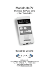
1
Model 5340V
Pulse Oximeter
For Veterinary Use
User's Manual
5 34 0
V
MEDIAID INC.
17517 Fabrica Way, Suite H, Cerritos CA 90703 USA
Tel : 714 367 2848 Fax : 714 367 2852
Email: [email protected] Web: www.mediaidinc.com
Model 5340V
Pulse Oximeter
For Veterinary Use
User's Manual
© Mediaid Inc - All rights reserved
1002-60017-002
Table of Contents
Chapter 1 : Principles of Operation .............................................................. 1
Intended Uses .................................................................................................... 1
Principles of Pulse Oximetry .............................................................................. 1
Principle of Measuring Body Temperature ......................................................... 1
Mode of Displaying Oxygen Saturation .............................................................. 2
Principal Features ............................................................................................... 2
General Cautions ................................................................................................ 3
Environmental Cautions ..................................................................................... 3
Chapter 2 : Keys, Indicators, & Symbols ....................................................... 4
Front Button Panel ............................................................................................. 4
Audible Features ................................................................................................ 8
Symbols ............................................................................................................. 9
Chapter 3 : Operating the Model 5340V .................................................... 10
Measuring Pulse Oximetry ............................................................................... 10
Measuring Body Temperature .......................................................................... 11
Faulty Reading & Sensor Complication Prevention ......................................... 12
Setting the Volume Level of the Audible Indicator ............................................ 12
Reading & Setting Alarm Levels ....................................................................... 13
Silencing & Reactivating Alarms ....................................................................... 13
Power ............................................................................................................... 14
Data Transmission ............................................................................................ 15
Tests ................................................................................................................. 16
Chapter 4 : Maintaining the Model 5340V ................................................ 20
Cleaning Instructions ........................................................................................ 20
Troubleshooting ................................................................................................ 20
Chapter 5 : Equipment Specifications ....................................................... 21
Oxygen Saturation, Pulse Rate & Temperature ................................................ 21
Alarms .............................................................................................................. 21
Analog Outputs ................................................................................................. 21
Serial Communication ...................................................................................... 21
General ............................................................................................................. 21
Sensors ............................................................................................................ 22
Power Source ................................................................................................... 22
Environmental Conditions ................................................................................. 22
Equipment Classifications ................................................................................ 22
Chapter 6 : Mediaid Inc., Limited Warranty ................................................ 23
Applicability of Warranty ................................................................................... 23
Warranty Coverage ........................................................................................... 23
Mediaid Inc. Problem Correction Plan .............................................................. 24
Owner’s Registration ........................................................................................ 24
Chapter 7 : Order Information .................................................................. 25
Contact Information .......................................................................................... 25
Product Information .......................................................................................... 25
Warranty Registration Form ..................................................................... 27
Principles of Operation
Chapter 1:
Principles of Operation
Intended Uses
The Model 5340V is intended to continuously monitor
an animal’s arterial oxygen saturation and heart rate. It
also provides body temperature information every two
minutes or on command.
Principles of Pulse Oximetry
WARNING
Before using the Model
5340V, the user should
become thoroughly
familiar with the
information in this manual
and with all information
included with the sensors.
The Mediaid Model 5340V Pulse Oximeter is designed
to measure the percentage oxygen saturation (%SpO2)
of functional hemoglobin. Non-invasive arterial oxygen
saturation measurement is obtained by directing red and infrared light through a
pulsating vascular bed. The pulsating arterioles in the path of the light beam cause a
change in the amount of light detected by a photodiode. The pulse oximeter
measures within the pulse waveform the ratio of transmitted red to infrared light, and
thereby determines the oxygen saturation of arterial blood. The non-pulsatile signal
is removed electronically for the purpose of calculation.Therefore, skin, bone and
other non-pulsating substances do not interfere with the calculation of arterial
oxygen saturation.
Principle of Measuring Body Temperature
The Mediaid Model 5340V’s temperature component is designed to measure the
animal’s core temperature with a rectal thermistor sensor.The thermistor’s highly
sensitive resistance decreases with increasing temperature. The LED display indicates
the animal’s body temperature.
PAGE
Principles of Operation
Mode of Displaying Oxygen Saturation
The Model 5340V displays pulse oximetry data as follows:
A normal steady display signifies that the pulse oximeter has received at least
three intelligible pulses in the last 30 seconds. The display is updated each time a
normal pulse is received.
A blinking display indicates that the Model 5340V has received no usable pulses
for at least 30 seconds. The displayed pulse oximetry readings are at least 30
seconds old.
A blinking display with a 1-second warning tone every 10 seconds indicates that
the Model 5340V has received no usable pulses for at least 60 seconds. The
displayed pulse oximetry readings are at least 60 seconds old.
Principal Features
The Mediaid Model 5340V Pulse Oximeter is a portable, lightweight instrument
designed to non-invasively monitor arterial oxygen saturation, heart rate and body
temperature. The principal features of the Model 5340V are as follows:
Displays with two bright Light Emitting Diodes (LEDS). Indicates oxygen
saturation, heart rate, and temperature.
Provides a constant readout of oxygen saturation in %SpO2 and heart rate in
beats per minute (BPM).
Issues an audible tone that sounds for each pulse and varies in pitch with
oxygen saturation - falling in pitch with reduced saturation and rising in pitch
as saturation increases.
Sounds a double tone to indicate each time the animal’s body temperature is
measured.
Provides visual and audible alarms for oxygen saturation and pulse rate
monitoring.
Allows for data transmission through the DATA PORT.
Performs a functional test at power-on. Additional diagnostics tests can be
initiated manually.
Alerts to a low-battery condition with a front-panel LED indicator.
Powered by either standard electric power or an internal, rechargeable
Nickel-Cadmium (NiCad) battery.
Compatible with all Mediaid veterinary sensors with RJ12 connectors.
PAGE
Principles of Operation
General Cautions
Federal law (USA) restricts this device to sale by or on the order of a licensed
veterinarian.
Proper operation of the oximeter and sensors may be influenced by patient
movement, dysfunctional hemoglobin and dyes.
Become thoroughly familiar with the information in the User’s Manual and all
accompanying documents before using the Model 5340V.
Take appropriate measures (such as powering off the Model 5340V) to Ensure
animal safety in case of abnormal conditions during operation of the Model
5340V.
Do not attempt to modify or repair the Model 5340V.
Dispose of the Model 5340V according to governmental regulations.
Environmental Cautions
Do not use in the presence of anesthetics or flammable agents.
Do not allow any liquid to penetrate the instrument’s interior.
Operate the Model 5340V in normal light conditions.
Do not use near Magnetic Resonance Imaging (MRI) equipment.
Keep away from other equipment, such as a defibrillator, which may affect the
accuracy of pulse oximetry readings.
Move the Model 5340V away from other electromagnetic emitting equipment if
there are any interference problems. This device complies with electromagnetic
compatibility standards EN550011 and EN60601-1-2.
PAGE
Keys, Indicators & Symbols
Chapter 2:
Keys, Indicators & Symbols
5340V
Front Button Panel
A. Power On/Off Key
The unit is powered on with one short depression
WARNING
(less than one second) of the POWER ON/OFF KEY.
A 1-second display and indicator test is performed
A non-functioning LED
automatically, and all Light Emitting Diodes (LEDs)
segment may yield
are illuminated. Carefully observe the LED displays
inaccurate readings.
for proper operation of all segments. A nonfunctioning segment will result in an incomplete
numeral and possible erroneous reading.
One long depression (3 seconds or longer) of the Power On/Off Key initiates the
Internal Confidence and Diagnostic Tests (see section “Tests” in Chapter 3).
B. Oxygen Saturation Display
Whenever the pulse oximeter receives at least three (3) pulses during a 30-second
period, the left LED displays the animal’s oxygen saturation levels. The display is
updated with every normal pulse.
PAGE
Keys, Indicators & Symbols
C. Pulse Rate Display
Whenever the pulse oximeter receives at least three (3)
pulses during a 30-second period, the right LED display
shows the animal’s heart rate in beats-per-minute (BPM).
D.Visual Pulse Rate Indicator
As soon as a pulse is found, the heartbeat is indicated by
a green LED. The VISUAL PULSE RATE INDICATOR
simultaneously flashes with the animal’s pulse. It typically
begins to flash a few seconds before numerical values for
oxygen saturation and pulse rate are shown.
WARNING
A blinking display
indicates that the Model
5340V has received NO
usable pulses for at least
30 seconds. The displayed
pulse oximetry readings are
at least 30 seconds old.
NOTE: If the unit is powered by battery and a pulse search is unsuccessful for any
reason, Model 5340V automatically powers off after one minute of unsuccessful
pulse search.
E. Low Battery Indicator
The LOW BATTERY INDICATOR illuminates when the battery is near depletion. In
order to continue battery-only operation, the user needs to suspend measurements
and recharge the battery (using the method described in section “POWER” in
Chapter 3).
NOTE: The pulse oximeter powers off shortly after a low-battery indication. The
Model 5340V displays acronym
if power-on is attempted during a low
battery condition.
F. Sensor Cable Connection
All Mediaid pulse oximetry sensors with RJ12 connectors are compatible with the
Model 5340V. To connect a sensor to the oximeter, align the plug with the jack on the
oximeter and insert it gently until an audible “click” is heard — indicating that the
plug tab is latched in place. To remove, squeeze the locking tab on the plug and slide
the plug out of the jack.
NOTE: The sensor might move slightly within the connector.
G. Power Connection
For electric power, plug the adaptor into the pulse oximeter’s POWER CONNECTION, and then plug the other end of the adaptor into a standard electrical outlet.
(All Mediaid pulse oximeters are designed to be used with the adaptor provided by
Mediaid Inc. at the time of purchase.)
H. Power Indicator
The green LED located on the bottom of the oximeter adjacent to the POWER CONNECTION illuminates when the Model 5340V is connected to electric power.
PAGE
Keys, Indicators, & Symbols
I. Data Port
The DATA PORT is used for serial and analog output. The DATA PORT should be
used only for connection to equipment that complies with CSA/IEC/UL601-1.
To eliminate risk of shock, take care not to touch the DATA PORT 8-pin Connector and the animal simultaneously.
J. Alarm Off Key
One short depression of the ALARM OFF KEY silences the alarm for a period of 60
seconds. One long depression of the ALARM OFF KEY completely disables the
audible alarm. The LED displays show
, the ALARM OFF INDICATOR begins
to flash, and the pulse oximeter reverts to normal monitoring. Silenced alarms can be
reactivated by one short depression of the ALARM OFF KEY. Disabled audible alarms
are reactivated by one long depression of the ALARM OFF KEY. The LED displays
show
NOTE: Visual alarm indicators cannot be deactivated.
K. Alarm Off Indicator
The ALARM OFF INDICATOR illuminates and remains on constantly when alarms
are silenced, and flashes when audible alarms are disabled.
L. Oxygen Saturation Alarm Key
One short depression of the OXYGEN SATURATION ALARM KEY toggles the display
between the high and low alarm settings, as shown by the HI/LO ALARM INDICATORS. These alarm settings can be adjusted with the INCREMENT or DECREMENT
KEY. The alarm settings will be retained in memory until changed by the user. Exception: When the low-saturation alarm is set below 80%, it returns to 80% at the next
power?up. The saturation alarm factory settings are: high 100% and low 85%. The
high-saturation alarm can be disabled by setting it at 100%. The Model 5340V
reverts to normal monitoring after a 5-second period of key inactivity.
M. Pulse Rate Alarm Key
One short depression of the PULSE RATE ALARM KEY toggles the display between
the high and low alarm settings as shown by the HI/LO ALARM INDICATORS. These
alarm settings can be adjusted with the INCREMENT or DECREMENT KEY. The
alarm settings are retained in memory until changed by the user. The pulse-rate alarm
factory settings are: high 140 BPM and low 50 BPM. The Model 5340V reverts to
normal animal monitoring after a 5-second period of key inactivity. Temperature
measurements can be initiated manually at any time with one long depression of the
PULSE RATE ALARM KEY.
N. Increment & Decrement Keys
The Model 5340V’s pulse-tone volumes can be adjusted using the INCREMENT or
DECREMENT KEY. There are three levels of audible pulse-tones, and “off.” The pulse
tone volume can be increased with the INCREMENT KEY and decreased or silenced
with the DECREMENT KEY. Alarm settings are also adjusted with these keys.
PAGE
Keys, Indicators, & Symbols
O. Hi/Lo Alarm Indicators
The HI/LO ALARM INDICATORS are located beneath the OXYGEN SATURATION
ALARM and PULSE RATE ALARM KEYS.These indicators flash when the animal’s
oxygen saturation or pulse rate reaches the preset high or low alarm limits. In order
to set the high alarm limits, the HI ALARM INDICATOR must be illuminated.To set
the low alarm limits, the LO ALARM INDICATOR must be illuminated.
P. Temperature Display
When a thermistor sensor is being used, the two LED displays indicate the animal’s
body temperature in degrees Celsius or Fahrenheit. Once monitoring begins, the
temperature is displayed every two minutes and is announced with a double-beep
audible tone. The temperature can also be measured at any time by one long depression of the PULSE RATE ALARM KEY.One long depression of the OXYGEN SATURATION ALARM KEY toggles the temperature setting (Cº or Fº).
PAGE
Keys, Indicators, & Symbols
Audible Features
Oxygen Saturation Indicator
A varying pitch of the audible tone signals a change in the oxygen saturation level a falling pitch indicates a decreasing oxygen saturation level, whereas a raising pitch
indicates an increasing oxygen saturation level.
Pulse Rate Indicator
A beeping audible tone signals the heartbeat. There are three volume levels of pulsetones, and “off.” The pulse-tone volume can be increased with the INCREMENT KEY
and decreased or silenced with the DECREMENT KEY .
Temperature Indicator
A double-beep audible tone sounds each time the animal’s temperature is displayed.
Alarm Indicator
Alarm conditions are generated only after an initial pulse has been detected. Alarm
tones are automatically silenced after the alarm condition goes away.
The HIGH PRIORITY alarm tones sound continuously at the highest frequency
and highest volume. HIGH PRIORITY alarms are caused by conditions such as
low and high oxygen saturation and pulse rate, no pulse, excessive ambient light,
and other error conditions.
The MEDIUM PRIORITY alarm tones sound for 0.75 seconds every 5 seconds at
the highest frequency and highest volume. MEDIUM PRIORITY alarms are
caused by measuring problems such as a disconnected sensor, too thin or thick
tissue, or a faulty sensor.
The LOW PRIORITY alarm tones sound for one second every 10 seconds at the
lowest frequency and highest volume. LOW PRIORITY alarms are caused by
excessive animal movement or an irregular heartbeat.
PAGE
Keys, Indicators, & Symbols
Symbol
Definition
Oxygen Saturation Display
Pulse Rate Display
Power On/Off KEY
Alarm Off KEY
Oxygen Saturation Alarm KEY
Pulse Rate Alarm KEY
Increment Key
Decrement Key
Data Port
Sensor Cable Connection
Power Connection
Low Battery Indicator
Attention: Consult Accompanying Documents
Non-anesthetic Proof
Type BF Applied Part
HI/LO Alarm Indicator
PAGE
Operating the Model 5340V
Chapter 3:
Operating the Model 5340V
WARNING
To ensure personal safety
and proper operation of
the Model 5340V, adhere to
ALL directions,
information, and cautions
stipulated within this
document.
WARNING
Animal movement, lightsource interference, or any
other disturbances that
occur for more than 30
seconds are indicated by a
blinking display. The
displayed pulse oximeter
readings are at least 30
seconds old..
WARNING
A non-functioning LED
segment may yield
inaccurate pulse
oximetry readings.
WARNING
Do NOT silence the
audible alarms if the safety
of the animal could be
compromised.
PAGE
Measuring Pulse Oximetry
To measure and display pulse oximetry, follow
these steps:
1) Choose an appropriate sensor.
2) Place the sensor according to the instructions with
the sensor.
3) Connect the sensor to the SENSOR CABLE CONNECTION of the Model 5340V.
NOTE: The sensor might move slightly within the
connector.
4) Follow all guidelines in section “Faulty Reading &
Sensor Complication Prevention” to prevent faulty
readings and sensor complications.
5) Power on the unit with one short depression of the
POWER ON/OFF KEY. The Model 5340V tests the
displays and the indicators with the initiated
POWER-UP TEST.
NOTE: One long depression of the POWER ON/OFF
KEY initiates the Internal Confidence Tests (see section
“Internal Confidence Tests” in Chapter 3).
6) Check that all LED segments light up during the
POWER-UP TEST.
7) Be sure that the VISUAL PULSE RATE INDICATOR is
flashing during the monitoring process
8) Read the animal’s oxygen saturation and heart rate
off of the OXYGEN SATURATION and PULSE RATE
DISPLAY.
9) Listen to the PULSE RATE INDICATOR.
NOTE: There are three volume levels of audible
pulse tones, and “off”. The tone varies in pitch with
oxygen saturation - falling in pitch with reduced
saturation and rising in pitch as saturation
increases.See section “Setting the Volume Level of
the Audible Indicator” in Chapter 3.
10) Set the pulse oximetry and heart rate alarm levels
according to section “Reading and Setting Alarm
Levels” in Chapter 3.
11) Silence and reactivate alarms according to section
“Silencing and Reactivating Alarms” in Chapter 3.
Operating the Model 5340V
Measuring Body Temperature
To measure and display body temperature, follow these steps:
1) Choose an appropriate sensor.
2) Place the sensor on the animal according to the
WARNING
instructions included with each sensor.
During insertion of the
3) Connect the sensor to the SENSOR CABLE CONRectal sensor, rectal
NECTION of the Model 5340V.
perforation can occur if
NOTE: The sensor might move slightly within the
excessive force is used. If
connector.
resistence is encountered,
Follow
all
guidelines
to
prevent
faulty
readings
and
4)
withdraw the sensor,
sensor or oximeter complications.
slightly change the
5) Power on the unit with one short depression of the
direction of the sensor, and
POWER ON/OFF KEY. The Model 5340V tests the
reinsert.
displays and indicators with the initiated POWERUP TEST.
6) Check that all LED segments light up during the POWER-UP TEST. (See section
“Power-Up Test” in Chapter 3).
7) Initiate the temperature measurement with one long depression of the PULSE
RATE ALARM KEY. The Model 5340V displays the temperature on TEMPERATURE DISPLAY. The Model 5340V automatically measures and displays body
temperature every two minutes.Measurements can be initiated manually at any
time with one long depression of the PULSE RATE ALARM KEY. A short doublebeep alerts the user to the display of the temperature.
8) Change the temperature display from Celsius to Fahrenheit or vice versa with
one long depression of the OXYGEN SATURATION ALARM KEY.
NOTE: The temperature range is set to measure between 24.5° and 42.5°
Celsius, or 76.1° and 108.5° Fahrenheit. When the temperature is below
24.5°C or 76.1°F the display is blank. An error message is displayed when the
temperature being detected is higher than 42.5°C or 108.5° F. (See section
“Troubleshooting” in Chapter 4).
PAGE
Operating the Model 5340V
Faulty Reading & Sensor
Complication Prevention
To prevent faulty reading and sensor
complications:
WARNING
In order to obtain accurate
pulse oximetry and
temperature readings,
choose an appropriate
pulse oximeter and sensor
according to the
intended use.
Turn off very bright lights, such as xenon
lamps, if they interfere with pulse oximetry
monitoring. In cases where such lights are
unavoidable, cover the sensor site with an
opaque material.
Consider conditions affecting the hemoglobin dissociation curve when
interpreting pulse oximeter readings.
Keep animal movement to a minimum.
Route sensor cords carefully.
Avoid applying excessive tension to the sensor or sensor cable.
Setting the Volume Level of the Audible Indicator
The Model 5340V issues an audible tone that sounds for each pulse. There are three
volume levels of audible pulse tones, and “off.” The tone varies in pitch with oxygen
saturation - falling in pitch with reduced saturation and rising in pitch as saturation
increases. The Model 5340V sounds a double beep to indicate each time the
animal’s body temperature is measured.
Set the volume level of audible indicators with one of the following actions:
Increase the volume level with one short depression of the INCREMENT KEY.
Decrease the volume level with one short depression of the DECREMENT KEY.
PAGE
Operating the Model 5340V
Reading and Setting Alarm Levels
The Model 5340V provides high and low alarm levels for oxygen saturation and
heart rate. The alarm levels are retained in memory until changed by the user, except
when the low saturation alarm is set below 80%. In this case, it reverts to 80% at the
next power-on. The factory settings for the saturation alarm levels are high 100% and
low 85%. The high saturation alarm can be disabled by setting it to 100%. The
factory settings for the pulse-rate alarm levels are high 140 BPM and low 50 BPM.
To read and set the alarm levels, follow these steps:
1) Read the low oxygen saturation alarm level with one short depression of the
OXYGEN SATURATION ALARM KEY. The red light of the LO ALARM INDICATOR lights up. Adjust the low alarm level with the INCREMENT or DECREMENT
KEY. The Model 5340V reverts to normal monitoring after a 5-second period of
key inactivity.
2) Read the high oxygen saturation alarm level with two short depressions of the
OXYGEN SATURATION ALARM KEY. The red light of the HI ALARM INDICATOR lights up. Adjust the high alarm level with the INCREMENT or DECREMENT
KEY. The Model 5340V reverts to normal monitoring after a 5-second period of
key inactivity.
3) Read the low pulse rate alarm level with one short depression of the PULSE RATE
ALARM KEY. The red light of the LO ALARM INDICATOR lights up. Adjust the
low alarm level with the INCREMENT or DECREMENT KEY. The Model 5340V
reverts to normal monitoring after a 5-second period of key inactivity.
4) Read the high pulse rate alarm level with two short depressions of the PULSE
RATE ALARM KEY. The red light of the HI ALARM INDICATOR lights up. Adjust
the upper alarm level with the INCREMENT or DECREMENT KEY. The Model
5340V reverts to normal monitoring after a 5-second period of key inactivity.
Silencing and Reactivating Alarms
Alarm conditions are generated only after an initial pulse has been detected. Alarm
tones are automatically silenced when the alarm condition goes away.
Silence alarms with one of the following actions:
Silence the alarms for a period of 60 seconds with one short depression of the
ALARM OFF KEY. The ALARM OFF INDICATOR illuminates and remains on
constantly until the alarms are reactivated again.
Completely disable the audible alarm with one long depression of the ALARM
OFF KEY. The LED displays show
, the ALARM OFF INDICATOR begins
to flash, and the Model 5340V reverts to normal monitoring.
Reactivate alarms with one of the following actions:
Reactivate silenced alarms with one short depression of the ALARM OFF KEY.
The ALARM OFF INDICATOR is no longer lit.
Reactivate disabled alarms with one long depression of the ALARM OFF KEY. The
ALARM OFF INDICATOR stops flashing. The LED displays show
.
PAGE
Operating the Model 5340V
WARNING
All Mediaid pulse
oximeters are designed to
be used with the power
adapter that is provided by
Mediaid Inc. at the time of
purchase. The use of any
other adapter may damage
the pulse oximeter and will
VOID the Mediaid Inc.
Warranty. Refer to the
product number of the
power adapter when
reordering a new adapter.
Include the serial number
of the Model 5340V as this
allows Mediaid Inc.
to determine the
adapter required.
WARNING
Avoid excess tension on
the adapter cable for safe
and continuous operation.
PAGE
Power
The Model 5340V can be powered by either a power
adaptor or the internal, rechargeable NiCad battery.
Battery operation alone will provide the Model 5340V
with approximately 12 hours of operation. Once electric
power is applied, the battery charges regardless of the
operational state of the Model 5340V. It takes approximately 5 hours to fully charge the internal NiCad
battery.
To charge the internal Nicad battery, follow these steps:
1) Connect the Mediaid power adapter to the POWER
CONNECTION located at the bottom of the Model
5340V.
2) Plug the power adapter into an appropriately rated
electrical outlet.
3) Check that the green POWER INDICATOR is lit.
Operating the Model 5340V
Data Transmission
Serial and analog data can be transmitted through
the DATA PORT (FIG. 1) to a peripheral device.
Figure 1
Serial Line
(TX)
Serial Data Transmission
Oxygen saturation data in the range of 0 – 100%
and pulse rate data in the range of 0 – 250 BPM can
be transmitted to a serial port of a data receiving
device. The transmitted data packet is comprised of
data bytes sent in the following order: Status byte,
%SpO2 byte, Pulse Rate byte, Temperature byte and
Checksum byte.The Status byte contains flags as to
the operational state of the Model 5340V:
Bit 7 :
Not used.
Bit 6 :
Pulse is lost, having previously been detected.
Bit 5 :
Pulse detected, normal monitoring started.
Bit 4 :
Error flag, indicating that an error is occurring.
Ground
Signal
Common
Serial Line
(RX)
Oxygen
Saturation
Analog
Output
Pulse Rate
Analog
Output
Bit 3 to 0 : Number of bytes in the data packet.
The %SpO2 byte contains the current oxygen saturation level. It is in 8-bit binary
format. The Pulse Rate byte contains the current pulse rate. It is also in 8-bit binary
format. The Temperature byte contains the current temperature and is in 8-bit binary
format. The range of numbers output for temperature is 42 to 229. To convert the
Temperature Byte to temperature in degrees Celsius, add 200 to the 8-bit binary
number and divide the result by 10. For example, ([229 8-bit binary number + 200]
/ 10) ºC = 42.9 ºC). The Checksum byte is the complement of the lower eight bits of
the bytewise addition of status, SpO2, pulse rate and temperature plus one. The data
field is 8 bits, one stop bit and no parity. Transmission speed is 9600 baud.
To transmit serial data, follow these steps:
a) Obtain the appropriate DATA PORT/Serial Cable from Mediaid Inc.
NOTE: Please refer to Mediaid Inc. for the availability of serial cables.
b) Verify that the Model 5340V is powered off
c) Connect the DATA PORT/serial cable to the DATA PORT..
d) Power on the Model 5340V with the power adaptor. The data is transmitted
automatically.
PAGE
Operating the Model 5340V
Analog Data Transmission
Oxygen saturation data in the range of 0-100% and pulse rate data in the range of
0-250 BPM can be transmitted to an analog port of a data receiving device. Analog
data is transmitted as follows:
0% SpO2
or
0 BPM
=>
0.000V
50% SpO2
or
125 BPM
=>
0.500V
100% SpO2
or
250 BPM
=>
1.000V
To transmit analog data, follow these steps:
1) Obtain the appropriate DATA PORT/Analog Cable from Mediaid Inc.
2) Verify that the data receiving device complies with CSA/IEC/UL 601-1.
3) Verify that the Model 5340V is powered off.
4) Connect the DATA PORT/Analog Cable to the DATA PORT.
5) Power up the Model 5340V. The data is transmitted automatically.
NOTE: Refer to the manufacturer of the data receiving device for additional
information.
Tests
NOTE: The Model 5340V has no user calibrations or serviceable parts. These tests
are provided for user assurance purposes only.
The Model 5340V can perform a variety of tests, which are described below. If an
error is detected during any given sequence, the test sequence terminates and the
characters
(an acronym for “error”) appear on the OXYGEN SATURATION
DISPLAY. The numeral representing the test during which the error occurred appears
on the PULSE RATE DISPLAY.The instrument must be powered off before testing or
monitoring can occur.
NOTE 1: If there is a low-battery condition at power-up, the Model 5340V shows
and the pulse oximeter powers off, prohibiting test functions.
NOTE 2: Some tests require audible, visual and/or operator supervision, and/or the
connection of an external device such as a sensor or voltmeter. The absence of
required peripheral devices results in an error message. Please read each of the test
description carefully.
WARNING
A non-functioning LED
segment may yield
inaccurate readings.
PAGE
Power-Up Test
One short depression of the POWER ON/OFF KEY
initiates a one-second DISPLAY AND INDICATORS TEST.
All LED segments must be illuminated for proper LED
functioning.
Operating the Model 5340V
Internal Confidence Tests
One long depression of the POWER ON/OFF KEY powers on the instrument, initiates
the DISPLAY AND INDICATORS, POWER CONDITION and EEPROM TESTS, and
displays the unit’s SOFTWARE VERSION NUMBER.The Model 5340V reverts to the
normal power-on sequence upon the release of the POWER ON/OFF KEY.
NOTE: Write down the instrument’s software version number (in the space provided
in section “Product Information” in Chapter 7). This number may enable Mediaid
Inc. to better assist the user.
Diagnostic Tests
DIAGNOSTIC TESTS on the Model 5340V can be run automatically or be initiated
manually.
NOTE: While in the test mode, either a single test may be run or all of the tests
may be run consecutively.
To initiate a DIAGNOSTIC TEST, follow these steps:
1) Verify that the Model 5340V is powered off.
2) While holding down the ALARM OFF KEY, perform one short depression of
the POWER ON KEY. The characters TST appear on the OXYGEN
SATURATION DISPLAY. The numeral 0 is displayed on the PULSE RATE
DISPLAY.
3) Display any other tests described below (TEST 0 - TEST 10), with the INCREMENT
or DECREMENT KEY. The appropriate test number is displayed on the PULSE
RATE DISPLAY.
4) Select a test by one short depression of the ALARM OFF KEY. The test runs and
stops automatically.
5) Revert to monitoring by first powering off the Model 5340V.
Global Test - Test 0
This test automatically initiates all of the diagnostic tests, which run automatically
and in order until either an error is detected, input is required, or the test sequence
is completed.
Display and Indicator Test - Test 1
Upon initialization of this test, the LED display segments and discrete LED indicators
are illuminated one at a time. Carefully inspect the proper operation of all LED
segments and indicators.
Audible Annunciation Test - Test 2
Both the variable pitch, audible pulse-tone, and audible alarms are annunciated by
the Model 5340V’s 8-pitch, 3-volume level audible annunciation system. This test,
when initiated, sequentially sounds all of the eight pitches (frequencies) and three
volume levels. Carefully listen for tone, pitch and volume changes.
Audible/Visual Alarm Test - Test 3
This sequence tests the instrument’s alarm functions. The audible alarm tone and the
four HI/LO ALARM INDICATORS are simultaneously activated for a period of
approximately 5 seconds. Audible and visual observation is required.
PAGE
Operating the Model 5340V
Control Key Test - Test 4
This test checks the functionality of the front panel control keys, excluding the
POWER ON/OFF KEY. Once initiated, the user must press the control keys, one at a
time, in the following order: ALARM OFF, OXYGEN SATURATION ALARM, INCREMENT, DECREMENT, and PULSE RATE ALARM. Do NOT press the POWER
ON/OFF KEY as it will power off the unit. An internal software routine waits for a
signal to be received from each of the keys. A unique number indicating the internal
memory address for each key is displayed. Observe the changing values to ensure
proper reception of each key’s signal.
Sensor Test - Test 5
This test requires an operational sensor to be connected to the pulse oximeter. The
functionality of the sensor, the pulse oximeter’s LED driver circuit, and the pulse
oximeter’s light-detection circuit are tested. This occurs by the emission of the sensor
light at a preset frequency and level, and the monitoring of the received signal from
the sensor detector.
Serial Communications Port Test - Test 6
This test is used in the factory only and cannot be accessed by the user after
production.
Reference Voltage Test - Test 7
It takes ten seconds to determine “Pass” or “Fail,” verifying the unit’s internal reference
voltage. The display is blank while the test is being run. A failure is indicated by the
display of
, and a pass is indicated by the next test being performed.
Analog Output Test - Test 8
The use of a voltmeter is required. To perform this test, follow these steps:
1) Connect one lead to PIN 6 (OXYGEN SATURATION ANALOG OUTPUT) and the
common output lead to PIN 7 (GROUND SIGNAL COMMON) of the DATA
PORT (see Chapter 3, “Data Transmission,” FIG. 1).
2) Once initiated, each depression of the ALARM OFF KEY tests the three saturation
values, which are displayed in the left window in ascending order. Observe the
voltmeter display to confirm a proper operation as listed below:
PIN 6
%SpO2
0%
= >
0.000V ± 0.001
50%
= >
0.500V ± 0.010
100% = >
1.000V ± 0.020
3) Connect the first lead to PIN 3 (PULSE RATE ANALOG OUTPUT) of the DATA
PORT to test the three pulse rate values as they are displayed in the right
window.
BPM
PIN 3
0
= >
0.000V ± 0.001
125
= >
0.500V ± 0.010
250
= >
1.000V ± 0.020
PAGE
Operating the Model 5340V
Internal Memory Test - Test 9
Upon initiation, this test checks each location of the pulse oximeter’s internal memory.
If all locations are functional, the number
is displayed.
Set-Up Test - Test 10
This test alternately displays %SpO2, pulse rate and internal circuitry set-up values. A
sensor needs to be applied to a subject. The instrument performs normal setup and
monitoring functions, and periodically displays single digit setup numbers: 0 for thin
tissue, 1 for medium tissue, or 2 for thick tissue. This test can only be exited by
powering off the Model 5340V.
PAGE
Maintaining the Model 5340V
Chapter 4:
Maintaining the Model 5340V
WARNING
Do not clean the
instrument while it is in
operation.
Cleaning Instructions
The Mediaid Model 5340V Pulse Oximeter can be
wiped clean with isopropyl alcohol or glutaraldehyde.
Avoid caustic or abrasive cleaners that will damage the
enclosure or keypad. Use extra care when cleaning the
red display window to avoid scratching the finish.
Troubleshooting
Problem
Possible Causes
Improper sensor application; area of sensor application too opaque; extraneous material obstructing the sensor LED and/or the photodetector
Ambient light too bright, direct light onto sensor
Internal failure of pulse oximeter
Low battery condition
(or)
Chirping Tone
WARNING
Do NOT attempt to open
the instrument case - doing
so will VOID the Mediaid
Inc. Warranty. Always
refer to the Mediaid Inc.
Warranty for service
instructions.
PAGE
Temperature reading above preset range
Data transmission failure
Equipment Specifications
Chapter 5:
Equipment Specifications
Oxygen Saturation, Pulse Rate & Temperature
Resolution
%SpO2 : 1%
Pulse : 1 BPM
Temperature : 0.18º Fahrenheit (0.1º Celsius)
Range
%SpO2 : 0 – 100%
Pulse : 32 – 250 BPM
Temperature : 76.1 – 108.5º Fahrenheit (24.5 – 42.5º Celsius)
Accuracy
%SpO2 : 100 – 70%, ± 2 Digits
69 – 60%, ± 3 Digits
Less than 60%, unspecified
Pulse : 32 – 250 BPM, ± 2 Digits
Temperature : ± 0.54º Fahrenheit (± 0.3º Celsius)
Alarms
High %SpO2 :
Low %SpO2 :
High Pulse :
Low Pulse :
51 – 100%
50 – 99%
31 – 245 BPM
30 – 244 BPM
Analog Outputs
% SpO2 : 0 – 100%, 0 – 1.000 V
Pulse : 0 – 250 BPM, 0 – 1.000 V
Plethysmographic Waveform : 0 – 1.000 V
Serial Communication
Protocol :
Baud Rate :
Data Field :
Data Field :
Bidirectional RS-232C Format
9600 baud
8-Bits, one stop bit, no parity
Status, %SpO2, Pulse,
Temperature, and Checksum
General
Two 3-digit, 7-segment LED
characters 1.0 cm. (0.4") in height
Dimensions : 19.7 (L) x 10.5 (W) x 3.8 (H) cm.
7.75 (L) x 4.25 (W) x 1.5 (H) in.
Weight : 516 g
18.2 oz
Display :
PAGE
Equipment Specifications
Sensors
Mediaid Opto-Plethysmographic pulse oximetry and temperature sensors with an
RJ12 connector and extension cable lengths 1.2 or 2.4 m / 4 ft or 8 ft Red Light wavelength 660 nm @ 565 µW Infrared Light wavelength 910 nm @ 1.8 nW
Power Source
NiCad rechargeable battery (12 hours of operation) or power adaptor input (100 – 250V
AC, 50/60 Hz, 0.5A). Power Adaptor Output - 15V DC 1.0A
Environmental Conditions
Atmospheric Pressure:
Relative Humidity:
Operating Temperature:
Storage/Transport Temperature:
1026 – 377 hPa (770 – 282.45 mm Hg)
5 – 95% (noncondensing)
32 – 104° Fahrenheit (0 – 40° Celsius)
-22 – l49° Fahrenheit (-30 – 65° Celsius)
Equipment Classification
The Mediaid Model 5340V Pulse Oximeter is classified according to CAN/CSA
C22.2 No. 601.1, EN 60601?1, and UL2601-1:
Type of protection against electric shock:
CLASS 1 AND INTERNALLY POWERED.
TYPE BF APPLIED PARTS.
Degree of protection against harmful ingress of water:
IPX 0 ACCORDING TO IEC 529.
Degree of safety of application in the presence of a flammable anesthetic mixture
with air, or with oxygen or nitrous oxide:
THIS EQUIPMENT IS NOT SUITABLE FOR USE IN THE PRESENCE OF A
FLAMMABLE ANESTHETIC MIXTURE WITH AIR, OR WITH OXYGEN
OR NITROUS OXIDE.
Mode of operation:
CONTINUOUS OPERATION
PAGE
Mediaid Inc., Limited Warranty
Chapter 6:
Mediaid Inc.,
Limited Warranty
Applicability of Warranty
NOTE
THIS PRODUCT IS SOLD
This warranty covers only the Mediaid Model 5340V
BY MEDIAID INC.
Pulse Oximeter and accessories as indicated. It is not
(hereinafter referred to as
extended to other products or components that the
Mediaid Inc.) UNDER THE
customer uses in conjunction with Mediaid Inc. products.
WARRANTIES SET
This warranty shall not apply if the manufacturer
FORTH BELOW.
determines that the product has been damaged due to
abuse, misuse, misapplication, accident, negligence,
tampering, or as a result of service or modification by any
other than an authorized Mediaid Inc. service technician. (Opening of the sealed
enclosure or altering the serial number will VOID the Mediaid Inc. Warranty.) Use
of equipment contrary to or inconsistent with the User’s Manual will also void the
warranty.
Warranty Coverage
Mediaid Inc. warrants that the Mediaid Inc. product enclosed with this warranty will
conform to the manufacturer’s specifications, and shall be free from defects in
workmanship and materials for a period of five (5) years from the date of original
purchase. Items excluded from this five-year term are the batteries, power adaptor,
sensor extension cables, sensors and other accessories.
PAGE
Mediaid Inc., Limited Warranty
Mediaid Inc. Problem Correction Plan
Should the Mediaid product prove to be defective, contact Mediaid Inc. by
telephone at:
714 367 2848
or
email: [email protected]
Please have the model and serial numbers available when calling. Mediaid Inc. will
then issue a Return Authorization Number (RAN). Return the instrument securely
packaged in its original shipping carton (or equivalent packaging), and include your
Return Authorization Number. Mediaid Inc. will repair any faulty workmanship, and
either repair or replace (at our option) any defective part with new or refurbished
parts. For non-warranty repairs, the customer will be charged the current repair rate
at the time of receipt by Mediaid Inc. All transportation charges shall be the
customer’s responsibility.
Mediaid Inc. shall not be liable for any damages including, but not limited to,
incidental damages, consequential damages or special damages. This warranty does
not cover any damage done to the equipment during shipping, which shall be the
sole responsibility of the transportation company.
ALWAYS READ THE USER’S MANUAL CAREFULLY.
The information included in the User’s Manual will assist the user in preventing
equipment misuse and ensuring patient safety. Operation of the equipment in a
manner contrary to or inconsistent with the User’s Manual will void the warranty.
Owner’s Registration
To assist Mediaid Inc. in better serving the user, please complete the included
Warranty Registration Card that is included and return it to:
Mediaid Inc.
17517 Fabrica Way, Suite H, Cerritos, CA 90703 USA
Telephone: 714 367 2848 Fax: 714 367 2852
NOTE: There are no warranties, expressed or implied, which extend beyond the
warranties set forth above. Mediaid Inc. makes no warranty of merchantability or
fitness for a particular purpose with respect to the product or parts thereof. This
warranty gives you specific legal rights. You may have other legal rights which vary
from state to state (or country to country, respectively). Mediaid Inc. will not be liable
to the user for incidental or consequential damage or loss arising out of the user’s
inability to use this product.
PAGE
User References
Chapter 7:
User References
Contact Information
For information on any other Mediaid products, visit the Mediaid Inc. home page
on the web at www.mediaidinc.com, or contact us at:
Customer Service
17517 Fabrica Way, Suite H,
Cerritos, CA 90703 USA
Returns Department
17517 Fabrica Way, Suite H
Cerritos, CA 90703 USA
Telephone
714 367 2848
Fax
714 367 2852
E-mail
[email protected]
Product Information
To better assist customers, Mediaid Inc. recommends all users write down all
pertinent product and warranty information in the space provided below.
Product Number:
POX010-5340V
Serial Number:
Software Version:
Power Adapter Product Number:
Warranty Expiration Date:
PAGE
PAGE
WARRANTY REGISTRATION FORM
Please return to Mediaid Inc. / local distributor for validation
Model
Serial Number
Date of Purchase
Institution/Physician
Address
Contact Department
Telephone
Distributor
Phone
Comments
PAGE
BUSINESS REPLY MAIL
MEDIAID INC.
17517 Fabrica Way, Suite H, Cerritos, CA 90703 USA
Tel : 714 367 2848 Fax : 714 367 2852
Email: [email protected]