1
CP6500-V
Functional Description
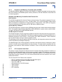
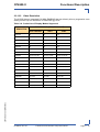
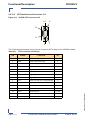
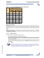
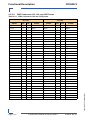
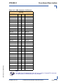
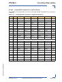
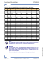
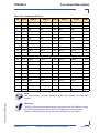
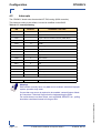
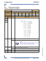
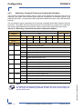
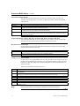
The following table provides the pinout of the CompactFlash connector J14.
28945.01.UG.VC.050304/090952
I/O
CompactFlash Connector J14 Pinout
FUNCTION
SIGNAL
PIN
PIN
SIGNAL
FUNCTION
I/O
--
Ground signal
GND
1
2
D03
Data 3
I/O
I/O
Data 4
D04
3
4
D05
Data 5
I/O
I/O
Data 6
D06
5
6
D07
Data 7
I/O
O
Chip select 0
IDE_CS0
7
8
GND (A10)
--
--
--
--
GND (ATASEL)
9
10
GND (A09)
--
--
--
--
GND (A08)
11
12
GND (A07)
--
--
--
5 V Power
VCC (5 V)
13
14
GND (A06)
--
--
--
--
GND (A05)
15
16
GND (A04)
--
--
--
--
GND (A03)
17
18
A02
Address 2
O
O
Address 1
A01
19
20
A00
Address 0
O
I/O
Data 0
D00
21
22
D01
Data 1
I/O
I/O
Data 2
D02
23
24
IOCS16
--
O
--
--
NC (CD2)
25
26
NC (CD1)
--
--
I/O
Data 11
D11
27
28
D12
Data 12
I/O
I/O
Data 13
D13
29
30
D14
Data 14
I/O
I/O
Data 15
D15
31
32
IDE_CS1
Chip select 1
O
--
--
NC (VS1)
33
34
IORD
I/O read
O
O
I/O write
IOWR
35
36
VCC (5 V)
Write enable
--
I
Interrupt
INTRQ
37
38
VCC (5 V)
5 V power
--
O
Master/Slave
CSEL (GND pullup)
39
40
NC (VS2)
--
--
O
Reset
Reset
41
42
IORDY
I/O ready
I
O
DMA request
DMARQ (INPACK)
43
44
DMACK
DMA acknowledge
I
I/O
Activity
DASP LED
45
46
PDIAG
ATA detection
I/O
I/O
Data 08
D08
47
48
D09
Data 09
I/O
I/O
Data 10
D10
49
50
GND
--
--
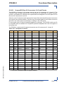
2.2.9
Front Panel LEDs
The CP6500-V is equipped with two LEDs for watchdog (WD) and overtemperature (TH), eight
LEDs for general purpose or POST code (four LEDs for Front-I and four LEDs for Front-II), and
one LED for hot swap. Their functionality is described in the following chapters.
ID 28945, Rev. 01
© 2005 Kontron Modular Computers GmbH
Page 2 - 9
PRELIMINARY
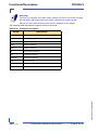
Table 2-5: