1
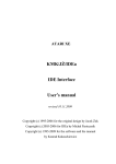
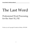
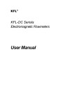
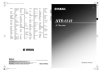
USER GROUP
TWAUG NEWSLETTER
( ISSUE CONTENT I
PUBLISHING!
This newsletter is set up with the
Desktop Publishing program
"TIMEWORKS 2", with a
Mega 1 ST and 4 meg of
memory. Files received are first
converted into ASCII format and
then transferred to the ST
usually with TARI-TALK. The
files are then imported into the
DTP and printed with the
CANON BJ-30 Bubble Jet
Printer at 360 dpi.
TWAUG
NEEDS
6$$
kw
YOU
TWAUG subscriptions
Home ....... 1 Copy ..... £2.50
- DO - ....... 6 Copies.. £12.50
Europe ..... 1 Copy ...... £2.50
- DO - ....... 6 Copies.. £13.50
Overseas.. 1 Copy ...... £3.50
-- DO -- ..... 6 Copies.. £16.00
Issue 32 is due mid-May 98
REMINDER & APOLOGY ..................... 2
CONTRIBUTIONS & CONTENT ........... 3
BUILDING INTERFACE ..........................
by Kenneth L. Siders ................................ 4
NOTE about DATA FILES ........................
ERRORS for MAGFILE 2 ....................... 5
XL-it &BIT EMULATOR .........................
by M a r h Gietzen ................................... 8
DUMMY CARTRIDGE
by Chad N.R.Knudson ............................ 18
THE FREEZER UPGRADE
Reprinted from A.C.E.C.BBS ................ 21
IDE WARD DRlVE INTERFACE .............
by Conradus .......................................... 23
FOR SALE .......................................... 34
DISK CONTENT ................................... 35
USER GROUPS ADVERTS ......................
for LACE & OHAUG ..................... ....... 36
TWAUG NEWSLETTER
Continued from page 2
I handed the ready printed master
copy to John for photocopying and he
was halfway through it when a most
horrible thing happened, the
photocopier decided it was time to go
on the sick. As you probably will know
that when anything is taken away for
repair, you never know when i t will be
returned and that is exactly what has
happened to our copier.
Talk about it being a jinx, or whatever
you want to call it, but we certainly
have had some bad luck with issue
30.
So please accept our apology for the
delay.
You are probably saying that we
could solve the problem by buying a
new copier, well it is easier said then
done. We certainly haven't got the
cash to spare for a new machine, it
costs plenty for the repair.
Our Email addresses
Alan's: [email protected]
John's: [email protected]
Max's: [email protected]
Type Interface (Instructions)
Kenneth L. Siders
ow to build a serial interface
(up to 19200 baud).
The following is the
description of how to build an RVerter
compatible interface. I have never
actually seen one so I derived most
of this from tracing the connections
inside an SX212 modem to determine
what pins on the SIO interface
corresponds to which on the RS232
connection (except the data lines
which are obvious). This interface
should work with any RVERTER (or
BOBVERTER) handler. It may work
with SX212 handlers or software but
may not support all of the baud rates.
Handlers are available alone and with
some terminal programs like
Bobterm.
I am not sure if all handlers support
19200 baud, but I have used my
interface connected via a null modem
cable to an IBM to transfer files at
19200 baud and have had no
problems. 1 tried 38400 baud (by
patching the handler) and too many
errors were generated. I also
connected by SX212 to the interface
instead of the SIO connection and
had no problems. I actually built this
by lightly super gluing the two ICS
into a large DB9 hood and soldered
TWAUG NEWSLETTER
the connections. I don't recommend
this approach unless you are totally
nuts. I would NEVER try that again
even though it did work (after fixing a
couple mistakes). I planned on
eventually filling it with EPOXY but I
didn't and pray nothing ever comes
loose. The cable I build has an SIO
cable (from my fried XM301 modem,
and the interface build in the other
end with a DB9 male connector. I was
able to use a ready made IBM cable
to connect to the modem. I also build
a null modem cable and gender
changer. This interface is unable to
communicate at the same time as
other I10 is occurring. This is typical
unless you have an interface that
connects to the XL/XE parallel bus.
Note: CTS is not supported so you
cannot use RTSICTS handshaking.
Only XONIXOFF could be used.
When transfering files between
computers, if you use a protocol this
will not cause a problem. No
reponsibility is assumed for any
damages resulting from the building
or using of this interface.
PI?
IC1 MAX232lICL232 RS232
Level Converter with onboard
+10V/-1 OV voltage generator.
IC2 74LS00 Quad NAND Gate.
Used to disconnect Data Lines
when DTR is not asserted.
R1 1K resistor 1/4W
R2 4K resistor 1/4W
(3K to 7K should be OK)
C1, C2 4.7uF capacitor
C3,C4,C5
1OuF capacitor
D1,D2,D3 IN4148 or IN914A
or similiar diodes
ZD1 IN4733 5.1V Zener Diode
or IN4734 5.6V Zener Diode
I don't have a data sheet for MAX232
and are giving the values for the
capacitors from another circuit. I used
33uF caps for all of them (I have a lot
of them I got cheap) and have had no
problems.~~lace
them as close to IC1
as possible. They should probably be
12 to 16 volt types or better
especially C3 and C4 which see
around 10 volts, where the other
three only see 5V.
L:mWu&n
next page
Please Note:
Whilst copying the Data Files for
Magfile 2 "MAG2DAT.An to
"MAG2DAT.Hn from the Master copy
these files have somehow been
corrupted. All those Data Files have
been included on this issue disk.
The Main program was checked to
make sure it was alright, but
unfortunately we never checked the
data files. We apologize for the
inconvenience caused.
TWAUG NEWSLETTER
l t a r i SIO
[connector o r
:able11
jnd [ 4 ) ---6ND---
Dl39 male
(IBM compat. 1
+
cs
~ S (10)
V
---VCC------
+
+
I I --+
I
+
+-11-+
I C l l
---- I---I
(1)
Cl+
+-11-+
I C 2 I
1 --- 1 ---- 1 ----(51
1
(3) [4)
I
C 1 - C2+ C2I
I
I
Iroceed [ 9 l ---- C \ I -------------- I (91 RPOUT
RZIN (8) 1 -- (1) CD
c/ I
I
I
Dl
(no connect ion) NC---NC----
(6) DSR
(83 CTS
O p t i o n a l (Only needed t o be a b l e t o d e t e c t r i n g s i g n a l from
Modem):
T h i s i s n o t t e s t e d , H o p e f u l l y i t does n o t need t o
be i n v e r t e d . You c o u l d p r o b a b l y use a 1 4 6 9 i f you know hon.
D3
RZ
TWAUG NEWSLETTER
Be sure to note polarity of capacitors.
Note: The positive lead of C4 does
go to ground smce the other leg will
be a negative voltage. + and 1 \ are
use to show connections and bring
connections together on the diagram.
Sorry not to break the ICs down into
parts but that would have made the
diagram worse.
Pins for RS232 are for a 9 pin
connector. With this connector you
can connect a standard 9 to 25 pin
cable to this connector to use a
modem, or a null modem cable to
iransfer files. You can substitute a 25
pin connector using table below. If
you plan on only using it for file
transfers you can wire in the null
modem cable before the jack.
Note: The 9 pin connections are not
the same as the 850 interface but are
the same as used sometimes on IBM
type computers. Change the gender
of the plug as desired.
9 Pin
1
2
3
4
5
6
7
8
9
25 Pin
8
3
2
20
7
6
4
5
22
RS232 Definitions:
CD=Carrier Detect (inp)
DTR=Data Terminal Ready (out)
D.IN=Data In(inp)
D.OUT=Data Out (out)
DSR=Data Set Ready (inp)
CTS=Clear to Send(inp)
RI=Ring Indicator (inp)
Null Modem connections
This is for 9 pin connector, if a 25 pin
connector is used use chart earlier to
convert.
Connect pin 5 straight through.
Cross in one end of the cable 2 with 3
and 7 with 8.
Connect 1,4, and 6 in each end of the
cable.
If you are only using the interface for
computer to computer transfers, you
can build this into the interface ii you
are careful. Connect what would go to
pin 3 to pin 2. Connect what would go
to pin 3 to pin 2. Connect what would
go to pin 8 to pin 7. Connect 1,4,6
together on the connector. Connect
what would go to pins 1 and 4
together. Connect pin 5 normally.
Parts Sources
Resistors, capacitors, diodes should
be available from Radio Shack (not
sure about the Zener diode if you
need it). The DB9lDB25
TWAUG NEWSLETTER
connectors and hoods should also be
available there.
Atari SIO cables are available from
one of the Atari Dealers - just remove
one end. You may also want to pick
up a prototyping board at Radio
shack to build it on.
The prices mentioned are for the US
and Canada.
I got the MAX232 for $1.65 and
74LS00 for 22 cents at BG Micro.
(US$ only,$lO minimum order on
credit cards) $3.25 minimum shipping
($750 Canada, $15 others, no
shipping to Mexico or Puerto Rico).
You could also get IN4148 diodes at
100/2.50. Other items that you could
get to pad an order if you need them:
14 pin socket 13/1.OO (only need
1),16 pin sockes 1311.OO (only need
I ) , 6821 PIA $2.00 (same as 6520?),
6810 (used in 1050) $1.25, 2793
(Controller used in 1050) $7.50,
41 64-15Ons RAMS at $0.49 or
9j3.50, 41 256-150ns RAMS at $1.25
or 9/9.95 (256Kx1), 62256 32x8
SRAM $5.00 (can this upgrade the
Black Box as described in the last
issue of the original A.C.?) Orders
1-800-276-2206, Tech suport
214-271 -9834, Fax 214-271-2462.
P.O. Box 280298 Dallas, TX 75228.
This along with a couple other places
was listed in one of the original A.C.
Issues.
XL-it! Atari 8bit Emulator
Version 0.20
User's manual
(c) 1996197 by Markus Gietzen
Contents:
*
Introduction
u Copyright
a
Installation
a Starting the emulator
fi User-interface
w Keyboard
a Monitor
The Author
F.A.Q.
*
Introduction
XL-it! emulates Atari 800, 800XL and
130XE homecomputer.
t is developed with Watcom C/C++
di ra needs at least a 386 CPU.
The emulator is optimized for the
use with Pentium processors.
Parts of the emulation are written in
386 protected-mode assembly (the
whole 6502-emulation and parts of
the Antic-emulation). The main goal
of the emulator is the ability to run
most of the existing software for Atari
8-bit home-computers. Therefore I try
to increase the compatibility first and
TWAUG NEWSLETTER
then I try to increase the speed and
the comfort of XL-it!.
Please note that an emulator can
never be like the original. It's just an
attempt to make it possible to use
your favourite Atari software on your
PC.
Copyright
XL-it! is (c) 1996197 by Markus
Gietzen.
Pokey-Emulator is (c) 1996197
by Ron Fries
XL-it! is free as long as it is not
used in any commercial matter.
This also includes all attempts to
include XL-it! in CD-collections that
are sold ! You need my written
permission first !
Donations are very welcomed!
I still have the right to forbid the
usage of the emulator at any
time.
I am not responsible for any
damage caused by XL-it!
Installation
Before you can start with the
emulator you must get the ROMs of
an Atari. These ROMs can be found
in an archive called "xf25.zipn which
is another emulator.
You can find that archive on the XL-it!
homepage (see chapter "The
Author").
Please place these ROMS in the
same directory as the emulator is
placed.
XL-ROM: atarixl-rorn (1 6384
Bytes)
BASIC-ROM: ataribas.rom (8192
Bytes)
OLD-ROM: atariosb.rom (10240
Bytes)
Sorry for this inconvenience but I am
not sure who owns the rights for
these ROMs and therefore I do not
include them.
Sound
All you have to do is to set the
"BLASTER" environement in your
"autoexec.bat". Please refer to the
documentation of your soundcard for
more details.
Attention: If you have an older
Soundblaster or compatible card that
doesn't support autoreload-DMA,
then you have to use "-oldsb". Of
course it's also possible to use the
user-interface for that.
Starting the emulator
The executable file is called
"atari.exe7'. It is a 32-bit DOSexecutable that runs under plain
DOS, Windows 95, Windows NT and
OS/2. For maximal performance
(above all if you use sound) I suggest
that you use plain DOS! This means
that you get a very slow emulation if
TWAUG NEWSLETTER
you use Windows 95 and soundsupport.
J hd dir Use H: to access directory
J artifact Enable color-artifacting
By starting "atari.exew without any
option you will be prompted by the
user-interface. This user-interface is
intended to be used instead of the
command-line options. This means
thar using any command-line option
disables the user-interface at start-up
(it still works within the emulator [F8]).
Therefore you can still use your
favourite emulator-launch utility.
Anyway, I don't think that you need to
stick around with the command-line
options anymore. The user-iaterface
is much more convienient and it
saves your setup on exit.
Command line Options:
J nobasic Disables BASIC
2
J cart fnameLoad 8k or 16k cartridge-image
Starts the emulation. You can leave
the emulation by pressing F8.
J About
Copyright
J DOS-Shell
Enter the DOS-Shell. With "exit" you
can exit this mode.
J Exit
Exits XL-it!
J Menu: Devices
You can insert disk-images into the
virtual DD-diskdrives of XL-it!
.XFD and .ATR images (single,
enhanced and double density) are
supported. The drives are called D l :
through D8: on the Atari.
J Harddrives
J oldmode Atari 800 emulation
10
J Menu: System
J Emulator
J Diskdrives
J nosound Disables SOUND
J nopatch Disables all 0s-patches
J joyswap Emulate joystick in port
J
J
J
J
J
J
User-interface options
modex 320x240 resolution
german German keyboard-layout
lock50 50Hz lock (PAL)
lock60 60Hz lock (NTSC)
frame x Displays every x.frame
This powerfull feature of XL-it! allows
you to access directories of your PC.
This means that you can access the
selected directories with H 1: through
H8:
J Insert ROM
oldsb Needed for older Soundcards
XL-it! supports 8k and 16k ROM
cartridges. If you have an image
March/April 1998
TWAUG NEWSLETTER
of such a cartridge you can load it
here (this only works on start-up; not
while the emulator is running).
J Eject ROM
Removes the ROM that you inserted.
J Menu: Setup
J Environement
This menu is only available at
start-up. It defines the general
behaviour of XL-it!. Options are:
J Sound
Selects whether sound should be
emulated or not.
J Old soundblaster
Check this mark if you have an older
soundcard (see Installation).
J XE-Emulation
If this mark is checked you have an
130XE with 128kB RAM. Of course
this only works as long as you don't
invoke Atari 800 emulation.
J 800er Emulation
Enables the emulation of an Atari
800. This disables the emulation of
the MMU and loads another
0s-ROM. This is needed for older
Atari software.
Enables/Disables the BASICcartridge. As a matter of fact you
have to disable BASIC for nearly
every game. This is a common
problem for Atari-beginners !
J Patch OS
XL-it! patches the OS to support
high-speed disk 110, access to your
PC-directories and other things. This
may lead to problems and therefore
you can disable that here. Anyway:
you'll lose many feature if you disable
0s-patching.
J Swap-Joysticks
This option is only available if you
don't have a PC-Joystick connected.
It means that the joystick is no longer
emulated in Port 1 but in Port 2
because there are a few games that
need that (mostly C64 ports). If you
have a PC-joystick connected it's
always in Port 1 and Port 2 is
emulated (keyboard).
J Deutsche Tastatur
This enables the German keyboardlayout.
J Video & Speed
J Framerate 1-10
If you have a slower PC then it's most
likely that XL-it! runs slower than a
real Atari. To archive more speed you
can skip frames. A side-effect is that
the collision-detection may fail in a
few games.
Hint: Even if XL-it! runs fast enough
try to use this function if you use
utilities (e.g. Assembler, BASIC etc.).
You'll like the speed !
J 320 x 240 resolution
TWAUG NEWSLETTER
The standard low-resolution of your
VGA-card is 320x200 pixels. The
Atari 8bit can display more than 200
lines on the screen. If you run into a
program that lacks parts of the
screen enable this option. Due to the
nature of the 320 x 240 video-mode
this slows XL-it! down.
J Color-Artifacting
This feature is introduced by v 0.1 9.
Have you ever wondered why you
saw colors in games like Loderunner
or Ultima? The answer is colorartifacting. This technique makes use
of the lower resolution of NTSC-TVs
(On Pal-TVs [like mine] this doesn't
look as good as on NTSC-TVs).
Anyway this feature tries to simulate
this behaviour. It's in an early stage
though.
J 50 Hz speed-lock, 60 Hz speed-
lock
you use it. A sign for a wrong
calibration are "ghost-moves". E.g.
you don't move the joystick but the
player moves on the screen. The
calibration-setup is saved of course.
Keyboard
XL-it! uses it's own keyboard-handler
to gather full control of the PCkeyboard. Therefore there is no
support for your country-specific
keyboard-layout (except Germany).
The default is the US/UK keyboard
layout.
Special key-assig iimenis:
F1 Option
F2 Select
F3 Start
F4 Help
If XL-it! runs too fast on your system
then you can lock the speed at 50 Hz
(PAL) or 60Hz (NTSC). This probably
only works good if your system is
about 15-20 frames faster than a real
Atari.
J Calibrate Joysticks
XL-it! supports a PC-joystick.
Unluckily the programming of support
for a PC-joystick is a nightmare. In
fact it's pretty easy but the hard part
are all those different joysticks out
there. Therefore it's necessary that
you calibrate your joystick before
F5 Break
F6 Toggle joystick-mode
0 F7 Enter Monitor
F8 Enter User-interface
Shift F8 Exit XL-it!
F9 Switch your virtual Atari off
and on again
F10 Reset
Alt Atari/lNVERS
Switching your virtual Atari on and off
again is very useful if a program
Marc h/April 1998
TWAUG NEWSLETTER
needs the option key pressed down
while your Atari powers up.
Just press down Option (Fl), keep it
pressed and then hit F9. You can
release F1 if the system is booting
(like an original Atari XLIXE). Of
course you can also use the
user-interface instead of this
procedure.
If you press F6, the ALT-keys will be
used as fire and the cursor-keys will
be used as the stick. By pressing F6
again, these keys will work as before.
By default the joystick is emulated In
port 1. Some games need ihe joystick
in port 2. here fore it is possible to
use port2 with "Swap-Joysticks". If
you have a PC-joystick connected
and it's detected by XL-it! then this
PC-joystick will be used to emulate
the Atari joystick. Please calibrate
your joystick (userinterface ->
"Calibrate Joystick).
Monitor
When you enter the monitor (F7), the
actual CPU-status is displayed. In
addition the average frame-rate since
the last monitor-session (or since the
start of the emulator) is displayed. If
you want to measure the frame-rate
for a certain screen, then this
procedure delivers a more exact
value:
0 enter the monitor
0 leave the monitor
@ wait 5-10 sec's
0 enter the monitor again
Attention: disk-access and switching
to the user-interface heavily disturbs
the measurement !
The following is an overview of the
monitor-commands. The goal of this
document can't be to explain you how
machine-code monitors work. The
monitor is mainly a debugging tool for
myself but it can be very usefull for
expierenced users, too.
Monitor-Commands
a xxxx Assemble starting- at $xxxx
d xxxx Disassemble starting at $xxxx
m xxxx Dump the memory at $xxxx
D xxxx Disassemble the display list at
$XXXX
: xxxx yy ... Set memory at $xxxx to
$W ...
s xxxx yyyy zz ...Search from $xxxx
to $yyyy for $zz ...
r reg xx Set a 6502-register to $xx
t Trace (single-step)
g xxxx Go until PC==$xxxx
p xxxx Set PC to $xxxx
c Display the contents of some
custom-chip registers
T newval oldval TrainermakerAssistant
TWAUG NEWSLETTER
L name xxxx Loads the file "name" at
$xxxx
? Display command-overview
x Leave monitor-mode
Some words about the TrainermakerAssistant:
Everytime you enter "T newval
oldval" the contents of the memory
are compared with the contents of a
backup-buffer and then the new value
is copied to the backup-buffer. This
means that you find positions that
changed from the old value to the
new value.
Example:
a
You start Boulder Dash and you
have 3 lives
Enter the monitor and give this
command "T 3 3" to initialize the
backup-buffer
When you die enter the monitor
again and make "T 2 3"
You will see the memory-positions that changed from 3 to 2
Enter ": memoryposition 8" and
you'll notice that you have 7 lives
(=8-1) when you die the next
time!
All in all it's not as complicated as it
looks like. Of course the above
method doesn't work with every game
!
The Author
I am a German college-student of
computer science. In 1998 1 will finish
the college with a master's degree. I
developed this emulator because I
always wanted to write an emulator.
As I liked my Atari 800 X L that
machine was the way to go. After a
few days (the 6502 emulation was
working and some basic graphicfunctions were working, too) I noticed
that this machine was great because
of its abilities and it is by far not as
easy to emulate this system as I
thought.
In addition I noticed that I forgot a lot
in the 7 years I had not used my
Atari. Therefore I want to say thanks
to all people on the Net who helped
me with their hints (please refer the
file "credits" for some special thanks).
If you want to contact me (for
feedback, questions or why ever), try
one of these Internet- addresses:
a
iig05-l @ htw.uni-sb.de
i? [email protected]
h WWW: http://myst.slcc.edu/-markus
I try to answer every mail but please
make sure that your reply- address is
correct ! It happened several times
that my answer was bounced !
If you do not have access to the
Internet, you can reach m e via
"normal" mail:
TWAUG NEWSLETTER
Markus Gietzen
Donations
image but you can also use the
virtual harddrive feature of XL-it!
Mount the directory (with the
user-interface) and then load the files
from DOS. I had good experiences
with DOS 2.5.
I develop XL-it! in my leisure-time. If
you use it on a regular basis, I would
appreciate to get a small (or not so
small :-) gift from you.
SpartaDOS and MyDOS actually
can't load the files from virtual
harddrives. Normally you will need to
disable BASIC first.
Ludweilerstr. 126
66352 Grossrosseln 1, Germany
Frequently Asked
Questions - FAQ
lease read this section before
you ask me or before you
post to a newsgroup. Anway
this doesn't mean that I'd kill you if
you ask a question that is answered
here.
Q:
What about .PRO format ?
A:
The .PRO format is an image-format
that is used by APE. This format is
not supported and will not be
supported.
Q:
What are .BIN, .COM or .EXE files ?
A:
These files can be everything. In the
most cases these are programs that
must be loaded from DOS. You may
transfer them to an .ATR or .XFD
Q:
The program XYZ does not work
although I was told that it works.
A:
Many programs need a disabled
BASIC or Option pressed down while
the power-up phase. If this does not
help, make sure that you have the
same version as the people who told
you that the program work.
Q:
How can I transfer files from my Atari
to my PC?
A:
You need APE or S102PC. This
means that you have to build a
simple cable that connects your Atari
or your Atari-periphery with your PC.
XL-it! will support this cable in a
future version, as well. (to be exact: it
will support the same cable that APE
uses to access Atari periphery ! The
so-called XFORMER-cable will not
work.)
TWAUG NEWSLETTER
When will the next version of XL-it! be
available?
A:
As XL-it! is not my main project I
cannot say when the next version will
be available. Therefore I suggest that
you read the newsgroup
"comp.sys.atari.8bit" and check the
XL-it! homepage on a regular basis.
Q:
There are some lines missing at the
top or at the bottom !
A:
Enable the 320 x 240 resolution. This
mode is not the default mode
because it is slower than the 320 x
200 resolution.
Q:
Q:
Why is there no source available ?
A:
I had bad experiences with releasing
sources of my programs to the public.
There are always some guys who
start making money with my work.
Therefore I only share code with
people who show me that they are
able to program and that I can trust
their words.
Q:
How can I change disks ?
A:
You can change the actual diskimages in the monitor (F7) but 1
suggest that you use the userinterface (F8).
I can't create a character disk with
XYZ and formatting does not work.
A:
Formatting disks is not yet supported.
Q:
The cursor-keys don't work !
Q:
How can I play games from a 2600 or
5200 ?
A:
The 2600 is completely different from
the Atari home-computer and
therefore there will be no support for
the 2600. The 5200 is very similar to
16
the Atari 800 system. I do not want to
say that I will never support it but
surely not at the moment. But there
are several emulators for these
systems out. (e.g. VSS by Dan Boris)
A:
XL-it! emulates the real cursorkeys of
an Atari. Many programs (e.g.
SpartaDOS) use "- = + *" to make life
easier on real Ataris without seperate
cursorkeys. Just use "- = + *" and it
will work.
(c) 1997 by Markus Gietzen
Msrch/Apnl 1998
TWAUG NEWSLETTER
SI02PC DESIGN
(618151--7;
1
o u t : 8-- :<-- 131
-------------- : *DIODE
By Rick Michael
NOTES:
f you're positive the cable will
never be used with other
peripherals like a 1050, you don't
need the diode. If you do use a
diode <recommended> make sure it
has a low forward voltage. In the
prototype I tried one with a 1.2V
forward drop & it failed to operate, but
a diode with a .65V forward voltage
drop worked like gang busters.
This means you can surely get away
with any germanium diode & probably
most small signal diodes like the
1N914.
NC means not connected, you don't
tie it to anything. Only pins 13 & 14
are tied together. If you feel bad
because the thing is too easy, you
can add a few more parts like a .l
Micro Farad disk capacitor between
pins 14 & 7 for decoupling. The funny
\ 1 on the 1489 are just an attempt to
.o show the inverting logic of the
1489. All parts can be had from your
local Radio Shack, but once again, I
hate Radio Shack &would recommend going anywhere else. The SIO
pin out when looking at the back of
the Atari is:
2 4
6
8 1 0 1 2
1 3 5 7 9 1113
Colors I've found in addition to what
Nick Kennedy found 4 & 6 Black & or
I
TWAUG NEWSLETTER
bare wire. Both of these are grounds,
one logic & the other shield. If you
really want to be sure you have a
good ground you can use both of
them. Black wire is pretty safe if
you're in a hurry & don't want to
bother.
SCHEMATIC
FOR DUMMY
CARTRIDGE
By Chad N. R. Knudson
10 + 5V Blue in every cable I've seen.
5 DATA OUT It's Green or Dark
Green on cables with two green
wires.
7 COMMAND Violet on some, light
green on others.
3 DATA IN & I don't think it comes in
any color but orange.
That's it, 5 connections to the Atari
serial cable, 4 to the IBM serial cable,
1 chip, 1 diode. The IBM connector
will have the numbers on the plastic,
but you may need a magnifiying glass
to see them. If somebody wants help
building a cable, you're better off
asking me about this one vs the MAX
or 7400 as I'm quite bored with them
& this circuit is IMO:
The obvious way to go.
Rick
his modification tricks the
computer into thinking a
cartridge is installed. This is a
terribly crude attempt at a
schematic for it, since the original
notes I had are quite old, and were
lust a few scribbles. I'm sorry that I
don't have better references to the
pins of the Atari board for the
cartridge port, but I'm sure you can
iigure them out.
T
Parenthesis in the diagram indicate
that the two lines are not connected.
-ik Pin 14 of the 7404 connects to
one side of the switch
-ik Pin 2 of the 7404 connects to
two of the cartdige port pins, all
other pins of the 7404 connect to
only one.
Mari 800 Computer upside down,
keyboard toward you.
This discription is for the first diagram
on next page.
I
TWAUG NEWSLETTER
+
+----------------------
+ 14 13 12 11 10
+
+
+
9
1
2
3
4
+----------------------
5
6
1 1 1 1 1 1
I
I +----- +
I I
I I Pins on bottom o f
I I LEFT c a r t r i d g e
+----+
I
I
+
+
+
++
7404 Hex I n v e r t e r
+
I
8 +
7
1
I
+-----------------------
+
I
I
I
c i r c u i t board f o r t h e
I I
I
I
I
I
I
I
I
I
I
I
DIAGRAM I
IlW
R
RD4
i4
+5V
13
I
I
I
I
I
I
+---- +
I
I
I
I
I
I
I
I
I
I
I
I 250 A
1
I
I ahmH
1
I
I t?lV
1
+---I
I
I
1
I
I
+------)-------)---------------------I
T I 44lCP
SH74LS04H
---------
I
-I8
-IS
-110
-111
-112
-113
l1 4
I
1- I
U LED
7 1I------6 1-
51413 1-
2 1 ---- +
I----A----I
+-------)----------------I +---------------
I
I
I
GHD
I
I I
+ I
I
11--+
010----+
-------
double-switch
DIAGRAM II
RD5
TWAUG NEWSLETTER
By Chad N.R. Knudson
Schematic for Dummy Cartridge
This modification tricks the computer into thinking a cartridge is installed.
[...I
he following does the same for a dummy 16K cartridge. A friend of mine
gave me this home made cart. Since I'm not an IEEE member, I just can
describe it:
T
This description below describes the Diagram II on the previous page.
Codes for the resistor:
Orange I orange I (purple - brown) / gold (250 ohm?)
Looking at the cartridge slot from the back (i.e. the space - bar is on the top),
the pins are as follows:
A
B
C
D
Pin R
R/W
14
RD4
13
B
A
+5V
E
F
H
J
K
L
M
N
P
R
S
Processor Read I Write
ROM present ($8000-$9FFF ?)
DC power supply
GND
Ground
RD5
ROM present ($A000-$BFFF ?)
David Davies <[email protected] wrote:
What's the point of having a dummy cartridge?' Is it useful for anything?
I used it to load an image of Atari Assembler/Editor, assemble and return to
BASIC to test the routine, without rebooting...
You can press the RESET key without loosing the code of the cartridge usually
wiped out by the screen memory.
... and sometimes to play some games copied from cartridges ;-)
Supplied by:
Craig Lisowski ([email protected])
TWAUG NEWSLETTER
UPGRADE
only checks a few bytes of memory to
The Freezer--cold-boot & protect
determine if the power was just
turned on (the locations would be
garbage), or if you had hit the RESET
key (the locations would equal
specific values). If, after powering off
and then on (in order to re-boot your
system), those bytes have retained
their data, the system may branch
through a warm (RESET key) start,
instead of taking the proper path
through cold (power on) start. T h ~ s
forces you to allow enough time to
elapse after power down for those
key addresses to lose ihe~rdata. A
repeat of power off/power on isn't
gomg to help unless you wait the
required interval (like 10 to 15
seconds...). This wa~iingaround is
very annoying - didn't you get this
extra ram to save time??
RAMdisk
Reprinted from the A.C.E.C. BBS
(614)-471-8559
THE FREEZER
here is one upgrade that can
be applied to an Atari XL/XE
which is near and dear to my
heart .... extra memory (256K).
Many programs that are only OK
when run from a disk drive, come
alive if you execute them from
memory. The Paperclip spelling
checker is a good example of this. If
you have a 256K machine, the
dictionary will load completely into
memory and will search a list of
words instantly. There are also
programs whose capacity is
increased tremendously by the 256K
upgrade. (Paperclip, a word
processor, will hold 112,000
characters vs. AtariWriter's 20,000 or
SO).
T
Great stuff, but..... a few complaints.
How do you use a ramdisk with a
program or DOS that is not written for
them?? Also, when you turn off the
power to a 256K memory chip, the
data that is stored in it does not
disappear in a few hundredths of a
second as it did with the older and
less efficient 16K and 64K devices.
The operating system, which controls
the power on and reset sequences,
So?? This is nothing new to those of
you that have expanded systems.
How do we fix it??
Relief arrives as a small hardware
modification that allows you to force a
cold start and boot the system with
the RESET key (which will normally
produce a warm start and no boot).
With this circuit installed, you can
re-boot your computer without turning
off the power and losing the data in
the extended memory banks, This
means that you can install a ramdisk,
load it with data and then re-boot the
system from the ramdisk. Using a
menu created for this purpose,
TWAUG NEWSLETTER
programs that do not support a
ramdisk - even a game, can be run if you can force a coldstart without
turning off the power (anyone want to
write the menu for this??) Also, you
could be operating with a ramdisk,
boot a different program, run for a
while, and then re-boot the original
program with the ramdisk memory
intact. And, of course, you don't have
to wait for the memory to blank out
after you power off. (a warm start is
cooled down to a cold start any time
you wish ..... hence, the FREEZER.)
This is accomplished by making the
computer think that you have
changed the status of the cartridge,
either removed one that you were
using, or plugged one in where you
had not had one before. During reset,
the operating system checks the
cartridge status since the last power
on. If it sees that the status has
changed, it executes a cold start and
re-boots the computer. This upgrade
allows you to change that status
when you press the FREEZER switch
(the one you will add). This means
that if you hold the FREEZER switch
down, push RESET (and OPTION, if
you don't want BASIC), and wait until
the screen goes black(off), you will
get a cold start. If you hold the
FREEZER switch down too long and
the screen restarts before you
release it, you can just push RESET
alone to cold start. Accidently hitting
the FREEZER switch while you are
running will lock your computer, but
as long as it is not active when you
RESET, it will not FORCE a cold
start. You may get one anyway if your
program is designed to produce one,
so mount the switch in a protected
spot. A little practice will get you a
cold start every time.
Installation requires some soldering
and cutting, so don't try this if you
haven't had experience. You will
need a 74HC86 IC, a small push
button switch and a 114 watt resistor
between 1K and 30K. Take your
1200XL, 800XL or 130XE apart and
locate the GTlA chip.
(1200XL=U19:800XL=U 17: 130XE=U1
7) You need to isolate pin 11 of the
GTlA from the rest of the circuit by
cutting the wiring on the printed circuit
board. The 130XE requires two cuts
and an added wire since the pin is
between two points that you would
like to keep connected. The normal
circuit is: pin 14 (RD5) of cartridge pin 8 of MMU - resistor to ground pin 11 of GTIA. In that example, you
could cut the wiring to pin 11 and not
remove any of the connection points
from the circuit except pin 1 1. In the
130XE, pin 11 is between the
cartridge and the MMU, so you have
to restore the wiring from cart. to
MMU after cutting out the pin.
1200XL: cut the trace on top of the
board just to the left of Q4. MMU is
U14.
TWAUG NEWSLETTER
800XL: cut the trace just below pin 11
on the GTlA chip (U17). MMU is U3
130XE: cut the trace on top of the
board just below pin 11 of the GTlA
chip (U17). Also cut the trace on the
bottom of the board right next to pin
20 of U17. Add a wire from the pad
near the last cut you made (near pin
20 of the GTlA chip) to pin 8 of the
MMU chip (U3). This added wire
restores the circuit between the
cartridge and the MMU.
All machines: the added circuit is 114
of a 74HC86, which is an exclusive-or
circuit. Wire pins 4,5,7,9,10,12, and
13 to ground. Connect pin 14 to +5v.
Pin 1 goes to pin 8 of the MMU and
pin 3 to pin 11 of GTIA. Connect a
114 watt resistor (1 K-30K) from pin 2
to ground. Finally, mount the push
button (normally open) switch on a
clear area of your case and wire one
side to +5v and the other to pin 2 of
the '86.
That is all that's needed. If you want
to restore your machine to normal,
solder a wire between pin 11 of GTlA
and pin 8 of the MMU and remove
the added IC and switch.
Well, it looks like it will take you
longer to read this whole thing than it
will take to build it. Just take your
time and ASK FOR HELP if you
aren't sure!!
<Uh,oh.... do I have to open up my
computer again??
Yep!! May be a good idea to install
MORRAM and FREEZER at the
same time and on the same board.
(takes two ICs - maybe you should
leave a little extra space for ....... ?)
IDE Hard Drive Interface
for Atari 130XE
From: CONRADUS@plearn .edu.pl
(KMK)
A message to Operating Systems/
Disk Operating Systems developers.
e are pleased to present
a preliminary document
about our IDE hard drive
interface for Atari 130XE
(and compatible) computers. As
existing Disk Operating Systems
aren't able to use all the capabilities
we provided, we are kindly asking
you to upgrade the latest versions of
your work and implement the specific
IDE features, those have been
described below. The four general
problems we found trying to use any
of the existing DOSes, are as follows:
1) All DOSes we tested, i.e.
SpartaDOS 3.29, SpartaDOS X 4.20,
MyDOS 4.53 and BWDOS 1 .lo,
when they have been executed,
seem to force the DUNlT (>0301)
value to >01. Such action is not
necessary, because the DUNlT is
already set by the XL OS's RESET
TWAUG NEWSLETTER
routines, and is obnoxious, because,
as a result, the DOS is unable to read
its config files, when the system has
been started from a partition other,
than Dl:.
2) All the DOSes we tested are
unable to readjwrite 51 2-byte sectors,
so they are unable to work in the IDE
native mode (see below). The
interface provides the emulation
mode to handle 256-byte sector
operations, but as a result the drive is
unable to reach its full speed.
Especially any writes to the hard drive
are very slow. The implementation of
the 512 byte allocation units may also
be profitable in the future, if we
decide to add support for DMA
transfers.
3) All the DOSes we tested are
unable to handle big partrtions (i.e.
over 16 ME limit). The ~mplementatron of the 51 2 byte allocation units
may solve this problem in a part (the
limit would be 32 ME per partition
then), but, if you decide to implement
big partitions handling, we advise you
to consider about using the 23-bit
sector addressing in conjuntion wrth
the larger allocation units (see below
for details).
4) All the DOSes we tested are
unable to handle disks D l 0-Dl 5.
Operating Systems developers
please note, that there is no necessity
to set the DUNlT value in the OS
BOOT routine, as the DUNlT is
already set by previous RESET
routines. We hope, that you will take
these problems into consideration,
decide to support the features
described below and don't hesitate to
send us your comments, if any.
Regards
Konrad Kokoszkiewicz
E-mail: [email protected]
S-mail: ul. Tomaszowska 95/37
PL-26-420 Nowe Miasto nad Pilica
POLAND
IDE Hard Drive Interface
v.l.0
a preliminary document
-
Copyright (c) 1995-1996 by Jacek
Zuk and Konrad Kokoszkiewicz
Made in Poland
The IDE package contains:
I ) the IDE interface
2) a power supply
3) a cable to connect the interface
with a drive
4) utilities disk with MyDOS 4.53
5) this document
Index rerum
TWAUG NEWSLETTER
I. Introduction
II. Capabilities overview
Ill. How to make it work (step by step)
IV. Keystrokes
V. Write-protection feature
VI. Executing non-DOS software
Vll. Dual drive configuration
VI II. Software development
information
IX. Memory usage
X. Error messages
I . Introduction
even years ago, when I first
heard about hard drives for
the Atari 8-bit, a 20 MB SCSl
device's price was over 600
USD and, of course, was out of reach
for people in a country on the wrong
side of the lron Courtain, where
wages were about 20 USD per
month. The 1050 floppy drive was a
dream - what would I say about the
hard one ...?
Over the next six years many things
have been changed. Among others,
the lron Courtain got rusty, we have
started earning more money, got
some new Atari computers and,
simultaneously, the prices of hard
drives have gone down dramatically ...
and one day I realised, that it is
possible to obtain an IDE hard drive
for the beloved 8-bit Atari with very
reasonable price! But there still was
no documentation and the only one,
that I knew, was a theory about
writing 'new device' handlers for the
XL operating system ...
The most important thing on my "way
to the hard drive" has happened,
when a friend of mine has found a
"Technical Reference Manual" for a
Caviar WDAC2200. I read thrs paper
very carefully, then went to Jack - a
person, who looks to know everything
about wires and other strange
gadgets, those have been fixed inside
and seem to make it work. About a
week later Jack said, that there was
no objections (contraindicatrons, as
we used to say) to build an interface so the project started.
The last year we spent thinking,
talking, building the hardware (Jack),
writing the software (me), testing,
fixing bugs, catching incompatibilities,
and learning, learning, learning. We
have discovered a lot of strange
things about Ataris and IDE hard
drives (some of them have been
mentioned below). Finally, we are
pleased to present you our results we tried to make them as professional, as it have been allowed by the
limited (2k) ROM space, not very
"elastic" operating system and not
very great processing power of the
Atari 8-bit computer. I hope you will
agree, that we did a good job.
TWAUG NEWSLETTER
II. Capabilities overview
The Interface's internal software
provides two modes: nativeand
emulation. The native mode uses a
51 2 byte physical block as a logical
data sector, the emulation mode uses
the physical block to store two 256
byte logical data sectors. ALL existing
DOSes require the emulation mode to
work properly.
Maximum drive capacity: 8388607
physical blocks on each device.
Maximum number of partitions: 15
computer is turned off.
2) Insert the interface to the
connector at the back side of the
computer.
3) Connect the interface and a 3 3 "
IDE drive with the cable.
Caution: You may damage the drive
if the interface cable is not connected
properly. Make sure, that pin 1 on the
cable (red line) is connected to pin 1
on the drive and on the interface (red
dot).
4) Connect the power supply and the
drive.
Maximum capacity of a partition:
8388607 logical sectors.
5) Insert ihe utilities disk into drive 1.
Logical sector length: 256 or 512
bytes (larger blocks will be implemented in the future).
6) Turn on the power on the hard
drive and on the computer holding
down the SHIFT key. Make sure the
drive is spinning up properly. If not,
turn the power off, check the
connections and try again.
Average speed: 58 kilobytes per
second (native mode, R/W) 32
kilobytes per second (emulation
mode, reading) 7 kilobytes per
second (emulation mode, writing).
Note: some very old drives need A
LOT of power, so our power supply
may not be sufficient.
Booting from any partition. Write
protection capability. 8 jumpers to set
the device number for the operating
system.
7) Be patient - the Interface waits
some seconds when the drive is
spinning up.
Note: ALL existing DOSes limit the
partition size to 16 MB.
8) When the MyDOS is ready to use,
execute the FDISK.COM file.
Ill. How to make it work
[step by step)
9) A menu should appear. If you see
a message like "Device not found"
instead, please turn the power off,
check the connection between the
1) Make sure, that the power on your
26
MarchlApril 1998
TWAUG NEWSLETTER
interface and the computer, then try
again. Check the jumper position.
10) Select the "Surface test" from the
main menu. Your drive will be tested
for bad sectors. If the test finishes
without any message, the drive is in
good condition - no bad sectors have
been found.
11) Select the "Partitioning" from the
main menu. "Total" will indicate total
amount of 512 byte sectors, that have
been found on the drive, "Remain" total amount of sectors, that haven't
been allocated yet, "Specs" will show
a number of cylinders, heads and
sectors per track.
12) Use arrows to select a drive you
want to be a partition.
13) Press the RETURN key and type
in a number of sectors you want to
allocated to the partition.
Note: it is a number of real 512 byte
sectors, so if you specify 32767, the
DOS partition will have 65534 logical,
256-byte sectors.
14) Press RETURN to confirm the
number of sectors or press ESC key
to cancel.
15) If you want to have more
partitions, repeat the last three steps.
16) Press the TAB key and select a
partition, that you want to be the
BOOT partition. If you are the
SpartaDOS X user and you want
to have the CONFIG.SYS on the hard
drive, the BOOT partition must be
D l :, so you should change the
physical number of your floppy drive
to D2: or another.
17) Press RETURN key to set the
BOOT partition.
18) Press the TAB key to move the
cursor to the menu at the bottom right
corner of the screen.
19) Select the "Opts" option.
20) Select the boot type according to
your system configuration:
- "control", if you want to boot up
MyDOS (or another DOS) from other
partition than D l : The interface will
take full control over the boot
process.
- "pass", if you want to boot up
MyDOS (or another DOS) from D l :
The interface will pass the control
over the boot process to the
operating system. Select this option,
if you have any troubles with the
"controlled" boot up - the interface,
taking the control over the boot
process, uses some hints that may
not work with some DOSes,
cartr~dgesor upgraded (customized)
operating systems. You MUST select
this option, if you are the SpartaDOS
X user.
21) Press ESC to exit the "Options"
menu.
TWAUG NEWSLETTER
22) Select the 'Write" option to write
the new partition table to the drive.
23) Press ESC to return to the main
menu.
24) Select the "Soft format" option
from the menu. The FDISK will
attempt to build new directories on
the attached partitions.
Note: the SpartaDOS 3.2 does not
provide such action - to do tt, you
must use a separate formatter, as the
P-FORMAT.COM.
25) Exit the FDISK.
26) Write the DOS file(s) to the BOOT
partition. If you are the MyDOS user,
select the "H" option from the DUP
menu. If you are the SpartaDOS 3.2
user, copy the DOS to the BOOT
partition and use the BOOT
command to make the disk bootable.
27) Press SELECTIRESET to cause
the cold boot. The DOS will load itself
from the drive - the installation
process is completed. Some IDE
drives used to clear the BUSY and
assert the READY bits in their internal
status registers *before* the spin-up
process is finished - the drive looks to
be ready, but isn't ready in fact and
cannot execute any commands (very
strange, by the way...). To prevent
such troubles during power up, the
internal software waits about 5
seconds before taking any action with
the IDE controller. This delay is not
necessary during the cold boot, that
has been caused by pressing
SELECTIRESET or via OS entry.
RESETCD (>E477). In such case the
internal software uses a fast
initialization method. However, if you
turn the power switch off and on very
quickly, the initial routines may not
recognize this boot process as a real
power up. As a result, the boot
process wilt crash. To prevent such
problems, after turning the power off,
you should always wait 10-15
seconds before turning it on again.
This time should be sufficient to
invalidate internal flags, that have
been located in RAM.
IV. Keystrokes
SHIFTIRESET disables the drive. The
drive will remain spinning, but the
partitions will not respond to
operating system requests (error
138). To enable it again just press the
RESET key.
SELECTIRESET forces the cold boot.
feature
The IDE hard drive interface provides
the write-protection feature to
minimize a risk of accidental data
damage caused by viruses, damaged
software or children. When a partition
is locked, there's NO POSSlBlLlTY to
write data to this partition or unlock
TWAUG NEWSLETTER
it by asserting commands, causing a
cold boot or turning the power off and
on. Damaging a write-protected
partition by writing accidental data to
random memory locations is also
'practically* impossible - the risk is
very small.
VI. Executing non-DOS
software with the hard
drive
Some software, especially games and
demos, have their own disk formats
and cannot be copied to a partition.
However, the IDE software provides
limited capabilities to execute such
programs.
If you selected the "controlled" hard
drive boot when partitioning the drive
and your BOOT partition is not the
Dl:,you may run the non-DOS disk
from the floppy drive. To do it, insert
the disk into the floppy disk drive then
press SELECT and RESET keys
holding down the SHIFT key. The
internal software of the IDE Interface
will pass its initialization routines and
your computer will boot up from the
floppy. The hard drive will be
"invisible" for the system.
,
If you want to execute such software
from the hard drive, you must provide
a small partition to use it in such
manner. Though the DIO-Dl5
partitions are invisible for existing
operating systems and cannot be
accessed by DOS, they may be
booted as well. When you are
partitioning your drive, create a small
(up to 520 physical blocks) disk, for
example D l 0:. When you complete
the installation and make the drive
work, execute the FHCOPY.COM file
from the utilities disk, then copy your
floppy to the DIO:.
Now execute the FDISK, select the
"Partitioning" option from the main
menu, then press the TAB key twice
to move the cursor to the menu at the
bottom right corner of the screen.
Select the "Opts" option, then set the
"Drive redirection" to D l 0:. If the
"controlled" boot-up has been
selected, you must change it now to
the "pass" mode. Write new partition
table, exit the FDISK and reboot the
system - the non-DOS program will
load itself from the hard drive. To
return to the previous configuration,
insert the utilities disk to your floppy
disk drive, reboot the system holding
down the SHIFT key, then execute
the FDISK, reset the "Drive
redirection" to D l : and "Boot type" to
its previous state, write the new
partition table, exit the FDISK and
reboot the system.
VII. Duai drive configuration
The IDE drive interface is able to
handle two IDE devices configured as
master and slave drives (please refer
TWAUG NEWSLETTER
the drive manual to connect it and set
up properly). However, some drives,
when they are configured to work as
the slave device, used to wait some
seconds before they start spinning.
For this reason, the Interface DOES
NOT INITIALIZE the slave drive
during power up or reset. It would
make little sense, because the drive
is not spinning (i.e. is not ready) at
that time. As a result, the slave drive
remains not in~tialized,even if the
boot process has been finished and
the system looks to be ready to use.
If the slave drive have finished the
spin-up process, there are two ways
to make it work properly:
1) assert the ALL RESET command
(see next section), or
2) force the system to read a sector
from any partition, that have been
allocated to the slave drive - if the
drive is ready, it will be recalibrated
automatically.
Please DO NOT start the operating
system from the slave drive partitions.
VIII. Software development information
The IDE drive partitions operate as
normal floppy drives or ramdisks and
can be accessed via OS DlSKlNT
(>E453) and SlOlNT (>E459)
routines. All the partitions recognize
the following commands:
R - read a sector - this command
reads a specified logical sector from a
specified partition. It reads ALWAYS
THE WHOLE LOGICAL SECTOR, i.e.
256 or 512 bytes, according to the
current mode and regardless of the
DBYT value. The sector number is a
24-bit value, the most significant byte
(now called DAUX3) is located at
>0307 (this byte was unused by the
XL 0s). Sector numbers less than
>000001 or greater than maximum
sector number for the specified
partition are invalid and will cause the
error 144.
P - put a sector - writes data to a
specified logical sector on a specified
partition. There are the same
restrictions, as mentioned above.
This command will return status 144
when attempting to execute on a
write-protected partition.
W - write a sector - the same, as "P"
command.
S - read status block - transfers the
4-byte disk status to the memory. The
bit of the first byte are as follows:
7 - not used by the hard drive
6 - write protection enabled
5 - double density drive (always 1)
4 - master present (usually 1)
3 - slave present
2 - not used by the hard drive
1) Standard subset
30
March/Apnl 1998
TWAUG NEWSLETTER
1 - not used by the hard drive
0 - not used be the hard drive
The second byte provides reversed
(eor'ed with >FF) value of the IDE
controller error register. The bits are
as follows:
2 - total number of logical sectors, the
middle byte
3 - total number of logical sectors, the
low byte
4 - total number of logical sectors, the
high byte
7 - BBD - Bad block detected
5 - additional information:
6 - ECC - Error correction code
(uncorrectable error)
5 - NUL - unused, always 1
bit 3 - IDE hard drive partition (always
I ) , bit 2 - double density drive
(always I), bit 1 - 8 inch floppy disk
drive (always 0).
4 - IDNF - ID not found (target sector
could not be found)
6 - number of bytes per logical sector,
high byte
3 - NUL - unused, always 1
2 - AC - Aborted command
7 - number of bytes per logical sector,
low byte
1 - TKO - Track 0 error (unable to find
8 - unused, always >FF
a valid track 0)
9 - value >49
0 - DAMNF - Data address mark not
found
10 - value >44
The normal (default) value of this
byte is 7FF. The next byte has a
dummy value >EO. The last byte of
the status block holds the number of
retries for the software IDE handler in
ROM.
N - read configuration - reads the
12-byte PERCOM block to the
memory. The values returned by a
partition are as follows:
0 - number of tracks (always 1)
1 - revision number (>I0 = 1.O)
11 - value >45
The last three bytes contain an
identifier Of the hard drive type
("IDE").
2) Specific ones >E6 - sleep drive stops the drives and deactivates their
internal controllers. See ALL RESET
command for the DCB variables
details. >E7 - all reset - resets,
recalibrates and reinitializes both
hard drives. It is the only way to exit
the Sleep mode. This command
needs the number of any partition
stored to the DUNIT (>o-301).The
TWAUG NEWSLETTER
master drive must be present while
asserting this command, otherwise
the timeout error will occur. >EC identify drive - transfers the 512 bytes
of data, that specify the drive's
parameters. The fields are as follows
(F = fixed value, V = variable, R =
reserved, should be zero):
0 - vendor specific information, bits
are as follows:
15 - 0, reserved for nonmagnetic
devices (F)
14 - vendor specific (F)
13 - vendor specific (F)
12 - vendor specific (F)
11 - vendor specific (F)
10 - vendor specific (F)
9 - vendor specific (F)
8 - vendor specific (F)
7 - removable media device, if 1 (F)
6 - removable controller and/or
device, if 1 (F)
5 - vendor specific (F)
4 - vendor specific (F)
3 - vendor specific (F)
2 - vendor specific (F)
1 - vendor specific (F)
0 - reserved (R)
2 - number of cylinders (F)
4 - reserved (R)
6 - number of heads (F)
8 - vendor specific
10 - vendor specific
12 - number of sectors per track (F)
14 - vendor specific
16 - vendor specific
18 - vendor specific
20-39 - serial number, ASCII
characters (F)
40 - vendor specific
42 - vendor specific
44 - number of ECC bytes transferred
on LONG operations (F)
46-53 - firmware revision, ASCll
characters (F)
54-93 - controller model number,
ASCII characters (F)
94 - numbers of sectorslinterrupt R/W
multiples, bits:
15-8 - vendor specific
7-0 - >00 = READWRITE MULTIPLE
not implemented (F)
>O1->FF = maximum number of
sectors that can be transferred per
interrupt on READWRITE MULTIPLE
commands (F).
96 - reserved (R)
98 - capabilities, bits:
15 - reserved (R)
14 - reserved (R)
13 - 1 = standard standby timer
values are supported
0 = standby timer values are vendor
specific (F)
12 - reserved (R)
11 - 1 = IORDY supported (F)
0 = IORDY may be supported (F)
10 - 1'= IORDY can be disabled (F)
9 - 1 = LBA supported (F)
8 - 1 = DMA supported (F)
7-0 - vendor specific (F)
100 - reserved (R)
102 - PI0 data transfer cycle timing
(F)
104 - DMA data transfer cycle timing
(F)
106-511 - reserved
TWAUG NEWSLETTER
All values are in standard lowlhigh
convention. Some parameters are
defined as a string of ASCII
characters. For the string
"Copyright", the character "C" is the
first byte, "o" is the second byte etc.
When such fields are transferred, the
order of transmission is:
- the 1st character ("C") is on bits 15
through 8 of the 1st word
- the 2nd character ("0") is on bits 7
through 0 of the 1st word
- the 3rd character ("p") is on bits 15
through 8 of the 2nd word
- the 4th character ("y") is on bits 7
I
of the 2nd word etc.
through !
(>0301) to the BOOT partition
number during boot up.
Note: the DMA transfers may be
supported by the drive itself, but may
not be supported by the current
version of the interface's hardware.
Please also refer the SLEEP DRIVE
command to get an information about
the DCB variables.
>EE - force media change - forces
the interface to re-read the partition
table from the drive.
You can get the following error
reports from the IDE drive:
138 - Timeout error - attempting to
read or write data to a partition, that
is physically allocated to the slave
drive, while the slave drive is busy,
not ready or does not exist at all; or
attempting to assert the ALL RESET
command, while the master drive is
not present. It may occur, if you
accidentally disconnect the master
drive or disconnect the slave drive
without reconfiguring your system. It
may also indicate a damaged
partition table - please reboot your
system. If this action doesn't cause
any effect, you must use the FDlSK
to repair the partition table. See also
section VII. - "Dual drive configuration".
139 - Invalid command
144 - Device done error:
All other commands will cause error
139 (negative acknowledge).
Note: that the software does not
provide a FORMAT DISK command
-it hasn't been implemented to
prevent an accidental data damage.
The drive must be formatted using a
separated program.
Operating system developers should
note, that the internal software of the
IDE Interface changes the DUNlT
IX. Memory usaw
The Interface's internal software uses
the following RAM locations: >01 and
234->3C. The PDVMSK (>0247),
PDVRS (>0248) and DCB variables
(especially DAUX3 >0307) should be
used only in their proper functions
(please DO NOT use them as
temporary data registers!). The
>0400->06FF area should also
remain intact during the cold boot.
TWAUG NEWSLETTER
1) the software attempted to write
data to a write-protected partition.
2) the software attempted to read or
write data outside of the limits, those
are valid for the partition.
3) there is a bad sector on the
partition. Please assert the "S"
command to get the value of the
internal IDE error register.
4) the ~nterface'ssoftware is unable
to handle your drive.
Please run the FDlSK and select the
"Surface test" from the main menu. If
the test fails and you know, that your
drive is in good condition (no bad
blocks) for sure, please assert the
IDENTIFY DRIVE command (from a
BASIC, for example), copy the buffer
to a file and send the file to us.
Konrad M.Kokoszkiewicz (KMK)
For Sale
Atari User Magazines: 1 to 4 in Binders,
also Page 6 New Atari User Magazine:
34 to 68 in 3 Binders. 25.00 per Volume,
Buyer collects or pay postage.
ATARI SOFTWARE: Visicalc 210.00
incl. P&P
Superscript 2 10.00 incl. P&P
Page 6 Printshop Collection 5 Disk Set.
f5.00 (needs Printshop program to use
disks). All original disks, Manuals
included. Sold by Tom Wood, but
PHONE Max: 0191 - 586 6795
For Sale
Continued fron previous column:
Also - Atari 800XL Upgraded to 256K,
1050 Disk Drive with write protect
switch & Happy Board fitted. Philips
Green Screen Monitor, 9 pin Epson
LX86 Printer and Disks & Magazines.
Sold by Tom Wood £120.00 or near
offer PHONE Max: 0191 - 596 6795
Atari 8-bit software: sold by Max
Flight Simulator 2 with scenery disk:
Star disk contains: San Francisco & The
Bay Area. Scenery disk 3: Scenery disk
4:
Scenery disk 5:
4 Books: Learning to Fly with Flight
Simulator - Flying on Instruments - 40
Great flight Simulator Adventures & 40
MORE Great Flight Simulator
Adventures: All Original disks and
includes Manual and Maps for each
Area. All incl. P&P X60.00 O.N.O.
Fighter Pilot: a real time Flight SmiIator.
F-15 Strike Eagle. Solo Flight.
Tomahawk a combat Helicopter. Raid
over Moscow. Blue Max 2001 & Pole
Position. 210.00 each or X75.00 the
Bundle. Also Transdisk IV & Mini
Office incl. or £5.00 each.
A 24 pin Printer STARbC24-100 with
Manual, 6 brand new ribbons and 14
re-inked ribbons and also 2000 sheets of
fanfold paper in box - all for X90.00 or
near offer. (must collect or pay P&P)
PHONE Max on 019 1 - 586 6795
... .. .
R
DISK CONTENT