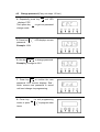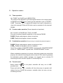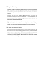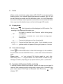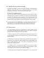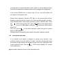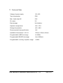
1
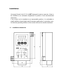
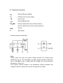
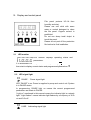
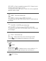
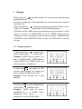
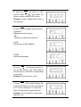
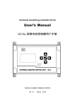
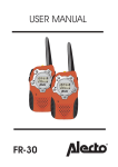
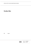
User’s Manual
用户操作指导手册
Universal Control Unit UC-1V
UC-1V 通用润滑系统控制器
Suzhou Leetern Industry Control
May 2012
Control Unit UC-1V is designed for controlling and monitoring of centralized
lubrication systems of engineering machinery, chassis and lubrication stations.
UC-1V stores control modes and parameters in EEPROM, which made UC-1V
can store data safely for long period without backup power supply.
The control unit uses LED monitor and LED signal lights to show information. It
is easy for operation.
UC-1V is a newly designed controller, which has advantages as:
l Use solid-state devices as primary output components, which can better
meet lubrication control requirements under harsh conditions such as low
pressure, high altitude and severe vibration, and more powerful current
outputs capacity.
l Using soft-starting technology to startup lubricating pump, avoid direct
starting has impact on pump and power supply system, which extend the
life of lubricating system.
l Optional automatic voltage adjustment function, which can automatically
adjust voltage within designed working voltage range to output voltage of
12V. Users only use a pump of 12V to adapt to power voltages of different
specifications.
l Reserved SIM SMS remote management function
l Fully compatible with controller UC-1N in control function, dimensions,
installation and operation interface, convenient for system upgrades
Factory settings on UC-1V are as followings:
Pause mode:
Timer
Pause time:
480 min( 8h )
Lube mode:
Timer
Lube time:
120 s ( 2 min )
System monitoring:
Pressure Switch
Without our written permission, any forms of translation, excerpt, copy,
print and reproduce of this USER MANUAL and its content is prohibited.
We reserve all rights to this USER MANUAL. We reserve the right to
revise it without prior notice.
Manufacturer:Suzhou Leetern Industry Control
Address: Rm.102, Building 8, No. 22, Xiao Shi Jia Nong, Suzhou, China
Technical Support Fax: +86-512-68661838
Technical Support Email Box: [email protected]
Website: http://www.leetern.com
Contents
Safety Warning!
1.
Installation
1.1 Installation dimensions
1.2 Electrical connection
2.
Display and control panel
2.1 LED monitor
2.2 LED signal lights
2.3 Keys
2.4 SL signal lights
3.
Operation guide
3.1
Display operation
4.
Programming
4.1
4.2
4.3
4.4
4.5
Start programming mode
Modify PAUSE mode and parameters
Modify LUBE mode and parameters
Change system monitoring settings
Change password
5.
Operating modes
5.1 Timer operation
5.2 Counter operation
5.3 Combination operation
5.4 Forced service
5.5 System monitoring
5.6 Power-off protection function
6.
Faults
6.1
6.2
6.3
6.4
6.5
6.6
Fault display
Fault message clearance
Operation with Pressure Switch monitoring
Operation with Cycle Switch monitoring
Block operation
Level switch detection
7.
Technical data
Safety Warning!
Universal Control Unit UC-1V is designed and manufactured not only in
conformity with the generally engineering standards, industrial safety
and accident prevention regulations, but also in accordance with some
relevant generally industrial technical acceptance standards.
Although this unit complies with relevant safety technical requirements,
the use of the unit may still entail dangers leading to personal injury of
the user or third parties or damage to property. Therefore, the unit must
be used when it is in perfect technical condition. And the operation must
strictly comply with operation manual. Errors that may affect safety must
be rectified immediately.
The unit is designed for controlling and monitoring centralized
lubrication systems. The user himself shall be liable for any damage
caused by improper use.
Potential electrical dangers
This unit must be connected to the power supply only by trained
qualified personnel in accordance with the local electric technical
regulations. Improper connection may lead to serious personal injury.
This unit is designed to use in battery-powered on-board electric system
of chassis, engineering equipment and lubrication station. When it is
used for any other purposes, all safety regulations should be complied
with.
Qualified personnel
Qualified person means person trained, assigned and instructed by the
operator of the equipment concerned. They are familiar with relevant
safety rules or regulations and have certain knowledge and skills of
safety.
They are entitled to carry out the activities required in a given case and
will be able to recognize and avoid possibly existing dangers.
Installation
Universal Control Unit UC-1V is NOT designed to work in open-air; it has to
be installed in an enclosed compartment to protect it from environmental
influences.
If the control unit is installed at an inaccessible position, it is advisable to
install additional signal lights and illuminated pushbutton in operation room.
So that the operating situation of the control unit can be remote monitored.
1.1
Installation dimension
1.2 Electrical connection
PS
External Pressure Switch
V+
Positive pole of power supply
+M
Pump motor
+SL
External Signal Light
DK/MK
External pushbutton (timer mode operation)
Counter signal input (counter mode operation)
GND
Ground
Z
Start-switch
External electrical connection:
Note:
Please make sure that the system voltage matches the voltage range
claimed for UC-1V. The fluctuation of supply voltage should be within the
limit of 11V~45V. Lower or higher than the voltage limit will permanently
damage the control unit.
If the lowest required voltage is not guaranteed, please purchase Low
Voltage Protector to protect the control unit against low voltage.
2. Display and control panel
Film panel protects UC-1A from
humidity and dust.
Please use soft cloth with warm
water or neutral detergent to clean
the film panel. Organic solvent is
prohibited.
Do not use sharp tools/ object to
touch the panel.
Please do not peel off the protection
film before its final installation.
2.1
LED monitor
LED monitor displays operating status and
parameters.
It is deactivated normally. To activate it, press key
, LED monitor
then start to display current status and programmed parameters. ※
2.2
LED signal light
PAUSE: Pause signal light.
LED “PAUSE” is on: Power is supplied to pump and control unit. System
is in PAUSE status.
In programming, PAUSE light on means the current programmed
parameters are relate to PAUSE.
“Light on” mentioned in this manual means the indicator light is a steady
light. ”Light flashes” means indicator light flashes by a frequency of 0.5s
on and 0.5s off.
LUBE:Lubricating signal light
LED “LUBE” on: Power is supplied to pump and UC-1V. System is now in
lubrication status (pump motor is running).
In programming mode, LUBE light on means the current programmed
parameter relates to LUBE.
TIMER:Timer mode indicator light
LED “TIMER” on: System is now in TIMER control mode.
In programming mode, light TIMER flashes means the control mode can
be changed.
COUNTER:COUNTER mode indicator light
LED “COUNTER” on: System is now in COUNTER control mode.
In programming mode, light COUTER flashes means the control mode
can be changed.
FAULT:Fault indicator light
LED “FAULT” flashes means fault occurs in the lubrication system.
Press key
, fault message will be displayed on LED monitor.
2.3
Keys
UPKEY
Activate monitor.
Increase with key
the displayed value at cursor position by 1 in
programming state. If the digit is already 9, then it will return to 0.
LEFT / DK key
To move the cursor position when input parameters in programming
status. If the cursor is already at the leftmost bit, then press this key, the
cursor will return to the rightmost position.
In PAUSE state, to initiate an lubrication by pressing key
once.
In FAULT state, to clearance fault message and get system back to
normal lubrication cycle by pressing key
once.
ENTER KEY
Activate programming mode. Confirm parameters.
NOTE: Programming operation can only be carried out when the system
at normal condition. If the system is in FAULT state, then troubleshooting
needs to be done first.
2.4 External Signal Light SL
If an external signal light SL has been installed, SL will flash for 3 seconds
after the start-switch is started.
Note: Control unit needs a certain time to save the operating parameters
at the point of power-down so that the lubrication task could be continued
after the break. The interval of the power-down and the next power-on
should not be shorter than 3 seconds. Otherwise, control unit may
not start properly, and SL will not flash.
Whenever the controller is performing the lubrication task, light “SL” will be
on, indicating the status of lubricating. If the controller detects any faults
during operating process, light “SL” will be flashing to remind user that the
lubrication system is in fault.
※
Under display mode or programming mode, if there is no key operations
for more than 2 minutes, LED turns off automatically and quit current
operation.
3.
Display
Briefly press key
to activate display. The current values and the preset
parameters are displayed.
During normal operation, LED signal lights are used to show current status of
the control unit.
Press and hold key
to activate programming operation. Please refer to
chapter 3.2 <Programming operation> for the detailed operation.
If PAUSE is set as TIMER mode, the measurement unit of the figure on LED
monitor is minute. If LUBRICATION is set as TIMER mode, then the
measurement unit of the figure on LED monitor is second. If LUBRICATION
or PAUSE is set as COUNTER mode, the figure on LED monitor is number
of times.
3.1
Display operation
1. Briefly press key
to show current
states, control modes and remain value.
Example: PAUSE light on means it is
now in PAUSE phase, TIMER light on
means PAUSE is in TIMER mode. And
remaining time is 162 minutes.
2. Press key
, the figure on LED
monitor starts flashing; this means the
figure is preset PAUSE control value.
Example: Preset PAUSE time is 480
minutes.
3. Press key
to show LUBRICATION
control mode and remaining value.
Example: TIMER light on means
LUBRICATION is in TIMER mode.
Remaining value shows ― ― ― ―
because it is now in PAUSE phase.
4. Press key
, the figure on LED
monitor starts flashing; this means the
figure is preset LUBRICATION value.
Example: Preset LUBRICATION time is
300 seconds
5. Press
to display system monitoring setting.
Displayed content may be:
PS
(Monitoring via Pressure Switch)
or CS
(Monitoring via Cycle Switch)
or OFF
(Monitoring disabled)
6. Press
, if monitoring function is
set as CS monitor, then LED displays
monitoring time. Otherwise, display skips
to next step.
Example: Monitoring time is 60s.
7. Press
, LED monitor displays the
3 high-order digits of the total operational
time. The first character “C” means the
value is accumulated operational time
Example: C105 means the 3 high-order
digits are 105.
8. Press key
, LED monitor displays
the 4 low-order digits of the accumulated
operational time.
Example: 1200. Compose the two digital
segments to get the total operational time
1051200 min.
9. Press key
, LED monitor displays
the 3 high-order digits of the accumulated
error time. The first character “E” means
the value is accumulated error time.
Example: C000 means the 3 high-order
digits of the value is 000.
10. Press
, LED monitor shows the
4 low-order digits of the error time value
Example: 0120. To compose the two
segments to get the accumulated error
time is 000120 min.
11. Press key
,LED monitor displays
“End.”, which means no more parameters
to be displayed.
12. Press key
. LED monitor goes
out and quit display operation state.
4.
Programming operation
Press
longer than 2 seconds to activate programming mode. All
preset parameters and control modes can be altered under this mode.
Please note: Programming operation always starts with steps 1-3 (input
password)
4.1
Activate programming mode
1.Press
longer than 2s, all pilot
lights on the panel off, LED monitor
shows“0000” to remind user to input
password
2. Input 4-digit password with key
Example: 1234
Factory setting is "0000"
.
3. Press key
to confirm the input
password. If the password is correct, LED
display switches to operation item.
Otherwise, controller quit programming
mode.
4.2
Alters PAUSE and LUBE values (Carry out steps 1-3 first)
4. Repeatedly press key
display shows PAU.
till LED
5. Press key
, light PAUSE on,user
may change PAUSE control mode now.
Pilot light on display panel indicate
present control mode.
Example:Timer mode
6. Press key
, to switch the control
mode between TIMER and COUNTER,
relative lights on panel will flash
accordingly to show user’s setting.
Example: New setting is counter mode.
7. Press key
to confirm the new
setting of PAUSE control mode, pilots
lights on panel then stop flashing, LED
monitor
displays
current
control
parameter of PAUSE.
Example: 480min
8. User may use keys
PAUSE value.
Example:
change to 540 min
to change
9:Press key
to confirm the new
parameter. LED monitor displays ‘End.’,
which means new control mode and
parameters are saved till next change via
programming.
10. Press key
mode; or press key
items.
to exit programming
to program other
4.3
Change LUBE mode and parameters ( carry out step 1-3 first)
4. Repeatedly press key
monitor displays ‘LUb’.
until LED
5. Press key
, light LUBE on, user
can change LUBE control mode now.
Pilot light on panel shows present LUBE
control mode.
Example: present LUBE mode is TIMER.
6. Use key
to change LUBE control
mode. Following the change, relative
lights TIMER or COUNTER will be
flashing accordingly.
Example:Change to COUNTER mode.
7. Press key
to confirm the new
LUBE control mode. Pilot light on panel
stop flashing and LED monitor then
shows preset LUBE control value.
Example:300 s
8. Use keys
parameter.
to change LUBE
Example: change to 180 s
9. Press key
to confirm the new
parameter. LED monitor displays ‘End’,
which means new control mode and
parameters are saved until next change
via programming.
10. Press key
to exit programming
mode; or press key
to program other
items.
4.4
Change system monitoring settings ( Please carry out step 1-3 first.)
4. Repeatedly press key
monitor displays ‘PCS’.
until LED
5. Press key
, light FAULT on, user
can change monitoring setting.
6. LED displays present monitoring
setting and the content of the setting is
flashing.
7. Use key
to change monitoring
mode.
Example:Change to CS – Cycle Switch
monitoring
Or OFF – monitoring disabled
8. Press key
to confirm the new
monitoring mode. If CS is set, then LED
displays monitoring time. If other mode is
set, then program skips to step 10.
9. LED displays present monitoring time
setting, user can use key
to
change the setting.
Example: Change to 120 s *.
10. Press key
to confirm the new
parameter. LED monitor displays ‘End.’,
which means new control mode and
parameters are saved until next change
via programming.
11. Press key
to exit programming
mode; or press key
to program other
items.
※
If monitoring time is set to 9999 (default ), then the monitor time function
is deactivated. UC-1V only detects weather Cycle Switch had action when
each lubrication process finish. By this to determine if there is CS error.
4.5
Change password (Carry out steps 1-3 first.)
4. Repeatedly press key
until LED
displays ’CPC’.
Then press key
to get into password
change mode.
5. Press key
password.
, LED displays current
Example: 1234
6. Use key
to change password.
Example:Change to 4321
7. Press key
to confirm the new
password. LED monitor displays ‘End.’,
which means new password is saved
until next change via programming.
8. Press key
to exit programming
mode; or press key
to program other
items.
5. Operation modes
5.1
Timer operation
Set “TIMER” for PAUSE and LUBRICATION.
The control of the lubrication cycle takes place based on the values preset
for PAUSE and LUBE times. It carries out the operation cycle of “PAUSE LUBE”. Press key
or external DK button can insert a lubrication or
clear fault message. External DK button can be connected to the terminal
DK/MK.
5.2
Counter mode operation (Pause depends on impulses)
Set “Counter” for PAUSE and “Timer” for LUBE.
Connect an external impulse transmitter to the terminal DK/MK.
PAUSE: Display and program values in impulses.
LUBE: Display and program values in seconds.
5.3
Combination operation (Pump running is controlled by external impulse )
PAUSE: Display and program values in impulses or time.
LUBE:Display and program values in impulses.
Users may combine “COUNTER MODE” of pause with “COUNTER MODE”
of lube, or “TIMER MODE” of pause with “COUNTER MODE” of lube.
When combination operation is in service, lubrication system may control the
pump by the method of counting the action times of CS.In order to guarantee
the lubrication system reliable operates, we suggest user to activate CS
monitoring function and set a proper CS monitoring time.
5.4
Forced service
Briefly press key
on the panel, controller will carry out a LUBE
process once.
Press and hold key
, controller will force the pump to operate until
release the key. During this process, controller does not carry out any
monitoring function.
5.5
System Monitoring
Controller can be set as Pressure Switch monitoring, to monitor the pressure
build up situation in main pipe. If pressure switch does not detect proper
pressure during lubrication period, fault will be automatically detected and
displayed.
Controller also can be set as Cycle Switch monitoring, to monitor the
movement of progressive distributor’s plunger. If Cycle Switch does not
detect movement of the plunger during lubrication period, fault will be
automatically detected and displayed.
If lubrication system does not need monitoring, please set monitoring as
OFF. Under this situation, lubrication circle only carries out lubrication by
PAUSE and LUBE control parameters and does not do fault monitoring.
5.6
Power down protection function
The control unit has power down protection function. When power is cut off,
the control unit auto stores operating status, remaining values and relative
system data at the point of power-off. When next electrify starts, the control
unit will continue carrying out operation from last point of power off.
The control unit stores operating status and values in EEPROM. The data
can reliable be stored for 10 years.
6. Faults
When control unit detects system faults, LED “FAULT” on the panel will be
flashing quickly. If an external Signal Light has been installed, light “SL” will
be also flashing to remind user the lubrication system is in fault. Meanwhile,
the control unit stops normal operation and wait for user to handle the faults.
User may check the detailed reason of the fault through LED monitor.
6.1
Display faults
Briefly press
,fault information will be displayed on LED monitor. The
meaning of the displayed information are:
No signal is received from Pressure switch during pump
running time.
No signal is received from Cycle switch during pump
running time.
Control unit detects error from Level switch.
Control unit itself has error inside. If such situation occurs,
get the control unit power off, then get it power on 1 minute
6.2
Clear fault messages
Press
or external DK button to clear fault messages(on the condition
that one state is set as COUNTER mode), and to start a normal lubrication
cycle.
Please note:
and external DK button must be used after
determining and correcting the faults. The user himself is liable for any
damages caused by operating the equipment without (lack of ) lubrication.
6.3 Operation with Pressure Switch monitoring
If external Pressure Switch has installed, system will stop once no signal is
received from pressure switch during pump running time. Controller then
gives alarm signal. FAULT light on the panel flash, Press key
, LED
displays “EP”.
6.4
Operation with Cycle Switch monitoring
If external Cycle Switch is used to monitor the movement of the progressive
distributor, system will stop once no signal is received from cycle switch
during pump running time. Controller then gives alarm signal.
The role of CS monitoring time is:
Each CS (Cycle Switch) corresponding matches an internal timer Tc. When
lubrication starts, Tc begins to countdown. If CS signal is received during the
countdown, Tc clears and re-start countdown. If no CS signal received until
the Tc countdown to the preset monitoring time, this means CS error occur.
controller will give alarm signal and system then gets into CS error state.
※
If monitoring time is set to 9999 (default ), then the monitor time function is
deactivated. UC-1V only detects weather Cycle Switch had action when
each lubrication process finish. By this to determine if there is CS error.
6.5
Block operation
If CS (Cycle Switch) monitoring is programmed, a block operation will be
automatically activated when no signal from the cycle switch is received
during the pump running time. To test Cycle Switch:
① When no signal from CS is received during the pump running period, the
normal lubrication operation will be aborted, then a 15 min interval block
operation begins.
② When the 1st 15 min block interval ends, controller drives the pump. If
signal from CS is received, the block operation will be ended. System goes
back to normal lubrication cycle. If still there is no signal from CS, then
another block operation begins.
③ If signal from CS is received during the 2nd 15 min interval, the block
operation is aborted and the system will go back to normal operation. If there
is no signal from CS, then the 3rd block operation begins
④ If the system receives signals from CS during the 3rd 15 min interval, then
it will go back to normal lubrication cycle. If there is still no signal received,
then the block operation is aborted and a fault message will be displayed.
If the preset PAUSE time is shorter than 15 min, the block pause will
correspond to the preset value.
During block operation, relevant LED light on the control panel will be
flashing to indicate that the control unit is now performing block operation.
Light PAUSE flashes means block operation is now in PAUSE state. Press
key
, LED monitor shows “bP”, light LUBE flashes, which means block
operation is now in LUBE phase. Press key
at this time, LED monitor
shows “bC”.
User may use key
to exit block operation earlier and get the system
back to LUBE phase.
Setting function is temporary deactivated during block operation period.
6.6
Level switch detection
If an external level switch is installed to monitor level situation, once
controller detects the level switch is closed, controller automatically stops
the system and gives alarm immediately. At the same time, Light fault on the
control panel will flash. Press key
, LED monitor displays ‘EL’ (means
level switch error).
※
Level switch detection function is an optional function.
7. Technical Data
Voltage of power supply:
12V~42V
Type of protection:
IP40
Max. Load output M:
20A
SL output:
5A
Data storage:
No limitation
Operation temperature:
-30℃~75℃
Storage temperature:
-45℃~85℃
Recommended fuse specification:
16A
Installation dimensions L×W×H:
137mm×92mm×42mm
Programmable LUBE time range
1s~9999s
Programmable PAUSE time range:
1min~9999min
Programmable counting impulses range:
1~9999
User Manual of Universal Control Unit UC-1V V0.1
May 2012
Notes
Notes