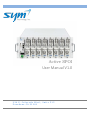
1
Active SPOI User Manual V1.0 234E.ColoradoBlvd.,Suite515 PasadenaCA91101 Active SPOI User Manual V1.0 THIS PAGE INTENTIONALLY LEFT BLANK Copyright ⓒ 2014 SYM Technology, Inc. All rights reserved. Page 2/48 Active SPOI User Manual V1.0 Revision History Date Version Description 11/10/15 1.0 Initial Copyright ⓒ 2014 SYM Technology, Inc. All rights reserved. Page 3/48 1. Active SPOI User Manual V1.0 Table of Contents 2. About this Guide............................................................................................................... 6 2.1. Who Should Use This Guide?..................................................................................................................................6 3. General ............................................................................................................................. 7 3.1. 3.2. 3.3. Warnings, Cautions, and Safety.............................................................................................................................7 HumanExposuretoRFRadiation......................................................................................................................7 Manufacturer’s Limited Warranty.........................................................................................................................8 4. Product Overview ............................................................................................................. 9 4.1. 4.2. 4.3. Introduction................................................................................................................................................................9 PartsList.....................................................................................................................................................................10 ActiveSPOIataGlance.........................................................................................................................................12 5. Installation ..................................................................................................................... 13 5.1. Mounting.....................................................................................................................................................................13 5.2. ControllerandRFLineCardConnections.....................................................................................................14 5.2.1. Controller:Host/DaisyChainSettings..........................................................................................................14 5.2.2. Controller:EthernetConnection.....................................................................................................................15 5.2.3. ‐48VDCInput:PowerConnection...................................................................................................................16 5.2.4. LineCard:RFCableConnection......................................................................................................................17 5.2.5. RFLineCard:PowerSelectionMode.............................................................................................................17 5.2.6. LineCard:MonitorPorts....................................................................................................................................17 5.2.7. LaptopNetworkSettings(PC)..........................................................................................................................19 6. Web GUI ......................................................................................................................... 21 6.1. Status&ConfigurationTab.................................................................................................................................23 6.1.1. MasterControllerUnit.........................................................................................................................................24 6.1.2. SlotCardSettings...................................................................................................................................................25 6.1.3. ActiveSPOIBlockDiagram................................................................................................................................26 6.1.4. ActiveSPOIManualOperation.........................................................................................................................27 6.1.5. ActiveSPOIAutoLevelControlOperation..................................................................................................28 6.1.6. ActiveSPOIHighPower&LowPowerDifferences.................................................................................29 6.1.7. CWToneGeneration.............................................................................................................................................30 6.1.8. iSpectrumIntegration..........................................................................................................................................31 6.1.9. AlarmSettings.........................................................................................................................................................35 6.1.10. SafeMode‐PowerLossBypassFunctionality..........................................................................................35 6.2. SetupTab....................................................................................................................................................................36 6.2.1. Setup>NetworkTab............................................................................................................................................36 6.2.2. Setup>Notification...............................................................................................................................................37 6.2.3. Setup>SNMPAgent..............................................................................................................................................40 6.2.4. Setup>Date&Time................................................................................................................................................41 Copyright ⓒ 2014 SYM Technology, Inc. All rights reserved. Page 4/48 Active SPOI User Manual V1.0 6.2.5. Setup>Account.......................................................................................................................................................42 6.2.6. Setup>Update........................................................................................................................................................43 6.3. AlarmHistoryTab..................................................................................................................................................44 6.4. StatisticsTab.............................................................................................................................................................45 7. Specifications ................................................................................................................. 47 Copyright ⓒ 2014 SYM Technology, Inc. All rights reserved. Page 5/48 Active SPOI User Manual V1.0 2. ABOUT THIS GUIDE This purpose of this document is to explain installation, setup, and operation of the Active SPOI DAS interface Tray by SYM Technology, Inc. It is intended to provide all the necessary information and guidance needed to use the system. The installation guidelines are of a general nature due to the wide variety of installation‐specific requirements within individual sites. SYM Technology prides itself on ensuring that installation is successful. Please contact SYM Technology directly if additional installation information is required (see section 3.3 for contact information). 2.1. WHO SHOULD USE THIS GUIDE? This guide is intended for use by trained telecommunication professionals responsible for base station (BTS)/Distributed Antenna Systems (DAS) performance, including: RF Performance Engineers Operations Engineers BTS & DAS Site Technicians SYM Technology assumes installation personnel will have an advanced understanding of RF engineering principles and typical BTS and DAS site architecture and installation procedures. It is the operator’s responsibility to ensure that this equipment is properly installed and operated within SYM Technology operating specifications in order to obtain proper performance of the Active SPOI and to comply with regulatory requirements. Warning: Failure to follow the installation and configuration recommendations contained herein may result in service interruptions and/or damage to the unit. Warning: This equipment may be installed in close proximity to cables, connectors, or components carrying high RF power. Installation and operation must be completed by qualified personnel. Copyright ⓒ 2014 SYM Technology, Inc. All rights reserved. Page 6/48 Active SPOI User Manual V1.0 3. GENERAL 3.1. WARNINGS, CAUTIONS, AND SAFETY There are several simple guidelines to operating the Active SPOI properly and safely. Avoid exposing the Active SPOI to extreme temperatures, either hot or cold. The Active SPOI is for indoor use only. Keep the unit in a clean, well‐ventilated, and dust‐free location. Avoid exposing the Active SPOI to rain or liquid spills. If the Active SPOI gets wet, immediately turn off the power and dry the unit completely. Treat the Active SPOI with care. Avoid dropping, throwing, or sitting on it. Rough treatment may damage the unit and void the warranty. Do not attempt to disassemble your unit. If the warranty seal has been broken, the warranty is no longer valid. Any changes or modifications to your unit not expressly approved in this document could void your warranty. 3.2. HUMAN EXPOSURE TO RF RADIATION This system complies with Part 15 of the FCC Rules. Operation is subject to the following two conditions: (1) This system may cause harmful interference. (2) This system must accept any interference received, including interference that may cause undesirable operation. Changes or modifications not expressly approved by the party responsible for compliance could void the user’s authority to operate the equipment. Note ! This system has been tested and found to comply with the limits for a Class A digital device, pursuant to the FCC Rules. Copyright ⓒ 2014 SYM Technology, Inc. All rights reserved. Page 7/48 Active SPOI User Manual V1.0 3.3. MANUFACTURER’S LIMITED WARRANTY SYM Technology Inc. (“SYM Technology”) offers a limited warranty that the enclosed unit (“Product”) will be free from defects in material or workmanship as follows: ONE (1) YEAR LIMITED WARRANTY: For a period of one (1) year from the date of original purchase, SYM Technology will, at its option, either repair or replace a defective Product (with new or rebuilt parts/replacement). LIMITED WARRANTY ON REPAIRED/REPLACED PRODUCTS: After SYM Technology repairs or replaces the Product, the repaired or replaced Product shall be covered by warranty for the remaining time of the original warranty period or for ninety (90) days from the date of repair, whichever is longer. Repair or replacement may include the use of functionally equivalent reconditioned units. Replaced faulty parts or components will become the property of SYM Technology. This limited warranty does not cover and is void with respect to the following: (i) Products which have been improperly installed, maintained, modified, or repaired; (ii) Products which have been subject to outdoor use, misuse, physical damage, abnormal use or operation, improper handling or storage, exposure to fire, water, excessive moisture, or extreme temperature; (iii) Products operated outside published maximum ratings; (iv) Products on which warranty seals or Product serial numbers have been removed, broken, or altered; (v) cost of installation, set up, removal, or reinstallation; (vi) signal reception problems or network problems (unless caused by defect in material or workmanship); (vii) damage as a result of fire, flood, power surge, lightening, acts of God, or other acts which are not the fault of SYM Technology and which the Product is not specified to tolerate; (viii) any Products which have been opened, modified, or repaired by anyone other than SYM Technology or a SYM Technology authorized service center. REPAIR OR REPLACEMENT, AS HEREINABOVE PROVIDED, IS YOUR SOLE AND EXCLUSIVE REMEDY FOR BREACH OF THE LIMITED WARRANTY. SYM Technology SHALL HAVE NO LIABLITY FOR ANY INCIDENTAL OR CONSEQUENTIAL DAMAGES, INCLUDING, BUT NOT LIMITED TO, LOSS OF PROFITS, LOSS OF SALES, OR LOSS OF USE OF THE PRODUCT. SYM Technology MAKES NO OTHER EXPRESS WARRANTY, EITHER WRITTEN OR ORAL, WITH RESPECT TO THE PRODUCTS. THE DURATION OF IMPLIED WARRANTIES, INCLUDING IMPLIED WARRANTIES OF MERCHANTABILITY AND FITNESS FOR A PARTICULAR PURPOSE, IS LIMITED TO THE DURATION OF THIS EXPRESS WARRANTY. SYM Technology Inc. Attention: Customer Service Phone: (626) 394‐6630, Email: [email protected] Copyright ⓒ 2014 SYM Technology, Inc. All rights reserved. Page 8/48 Active SPOI User Manual V1.0 4. PRODUCT OVERVIEW 4.1. INTRODUCTION The Active SPOI is an innovative approach to remotely managing the power levels of DAS systems. The modular design allows the user to mix and match cards with different frequencies for complete customization. A fully loaded chassis with all eight line cards installed will support four sectors with a MIMO configuration for one frequency band. The innovative graphical user interface (GUI) design is very intuitive and was developed to be so simple to reduce training requirements and ease the use of operation. This unit also handles both high and low power radios, up to 48 dBm on High Power Mode and 38 dBm on Low Power mode with insertion loss of 13.5 dB and 3.5 dB respectively. In case of a power failure, the active SPOI bypasses to the safe mode to ensure continuous service. Up to 15 shelves (units) can be daisy chained together in a Host‐Remote configuration. The design has been engineered to make remote access as user friendly as possible with a single connection to the Host unit allowing the user to control all of the Remote units from the single connection. Users have 24/7 access to the system once it is properly installed. Multiple personnel can access the Active SPOI simply by using an Internet connection to log on to the Web‐based GUI. Users can view and adjust power levels, modify configuration settings, and set alarm threshold levels as well as many other actions found in this manual. The Active SPOI monitors the downlink input power changes and displays the values in a user‐friendly graphical chart. The power level is measured hourly and recorded in the log file where the results are analyzed and displayed for one year's worth of data providing a useful tool for trending and analysis reporting. This product has been engineered to integrate seamlessly with the SYM iSpectrum which provides a live spectral view of the attenuation (insertion loss) changes made in the active SPOI. The Active SPOI sends out SNMP V2c and V3 based alarm notifications. There are 7 alarm parameters including DL input overpower, UL input overpower, DL input low power, LNA, FAN, PLL, and Temperature. The alarming feature generates alarm reports over a user‐specified time period based on alarm counts. More information on these features as well as all information necessary to properly use the Active SPOI will be described in the following chapters. The steps required to install and configure the Active SPOI will be described in detail. However if information or assistance is required, please contact: SYM Technology, Inc. Attention: Customer Service Phone: (626) 394‐6630, Email: [email protected] Copyright ⓒ 2014 SYM Technology, Inc. All rights reserved. Page 9/48 Active SPOI User Manual V1.0 4.2. No PARTS LIST Item Description Qty. 1 SP‐MFC Main Frame Chassis and Controller 1 2 DC Power Cable ‐48VDC Power Cable 6 ft 1 3 Ethernet Cable (RJ‐45) Straight Cable 3 ft 1 4 RF Card* RF Interface Card 8 *RF Card: RF Cards are separately packed. Table 4.2a. Part List PART NO. RF CARD DESCRIPTION DL FREQ. UL FREQ. S700C 700MHZ UPPER C BAND 746‐757 776‐787 S850 850MHZ CELLULAR BAND 869‐894 824‐849 S1900 1900MHZ PCS BAND 1930‐1995 1850‐1915 S2100 2100/1700MHZ AWS BAND 2110‐2155 1710‐1755 S800S 800MHZ SMR BAND (SPRINT) 862‐869 817‐824 S800N 800MHZ SMR BAND 851‐869 806‐824 S2600 2600MHZ BRS BAND 2496‐2690 2496‐2690 S700A 700MHZ LOWER ABC BAND 728‐746 698‐716 Table 4.2b. RF Card List Copyright ⓒ 2014 SYM Technology, Inc. All rights reserved. Page 10/48 Active SPOI User Manual V1.0 Figure 4.2a. Active SPOI Views Copyright ⓒ 2014 SYM Technology, Inc. All rights reserved. Page 11/48 Active SPOI User Manual V1.0 4.3. ACTIVE SPOI AT A GLANCE The Active SPOI is a system designed to provide complete RF power control with advanced active features for manual or automatic power level adjustments. The unit consists of a chassis with a control module and up to 8 plug and play, hot swappable line cards that can be mix and matched between line cards with different frequencies. Power&StatusLEDs DASPower Connections MonitoringPorts USBfordebugging High/LowPower LANPortforLocal JumperPorts Access CascadePort WAN/CascadePortfor Power&Status HostWANRemote LEDs AccessorDaisyChain Unitcascading PowerSwitch RFTX/RXPort ‐48VDCPowerInput Controller&Power RFLineCard Figure 4.3a. Active SPOI Controller/Power and RF Line Card External View Copyright ⓒ 2014 SYM Technology, Inc. All rights reserved. Page 12/48 Active SPOI User Manual V1.0 5. INSTALLATION 5.1. MOUNTING The Active SPOI is a 19‐inch rack mountable unit. It can be mounted into a 2‐post rack utilizing faceplate mounting. The faceplate with side‐securing elements can be placed at the front, rear, or both ends of the unit. a. 2‐Post Mounting When the Active SPOI is installed in a 2‐post rack system, a 19‐inch supporting shelf will not be required. A detachable side‐mounting bracket can be mounted at the middle of the Active SPOI as shown below. Mounting brackets at the middle of the unit will allow for 2‐post rack mounting. Figure 5.1a. Active SPOI Mounting on 2‐Post Rack Copyright ⓒ 2014 SYM Technology, Inc. All rights reserved. Page 13/48 5.2. Active SPOI User Manual V1.0 CONTROLLER AND RF LINE CARD CONNECTIONS 5.2.1. Controller: Host/Daisy Chain Settings The Daisy chain mode is selectable through the local web GUI connection only. In case of remote connection, the SET button won’t be displayed in order to prevent changing its mode mistakenly. The Node information is configured on the main controller unit (MCU) by selecting either Host or Remote (1 to 14) for the daisy chain connections. Host Unit Mode: This designates the unit as the Host Controller and all Remote units that are connected to the host will be controlled via the Host GUI, which allows for a single point of interface and ease of use. By default, all units are set as Host. Host Controller is assigned the IP address of: 192.168.169.100. Remote Unit Mode: This designates the unit to the Remote Controller (1 to 14). The IP addresses are automatically assigned from 1 to 15 in the order of the daisy chain for easier operation and maintenance. (See Section 5.2.2) Figure 5.2.1a. Controller Host/Remote Settings Copyright ⓒ 2014 SYM Technology, Inc. All rights reserved. Page 14/48 Active SPOI User Manual V1.0 5.2.2. Controller: Ethernet Connection The Ethernet ports are located on the front panel of the main controller as shown in section 4.3. LAN Ethernet Port (for laptop connection) The Active SPOI can be configured locally with the built‐in web‐based graphical user interface (GUI). Using a standard Ethernet cable, connect your laptop to the “LAN” port on the Controller. The LAN connection is simple to set up. The LAN connection should be used for initial setup and whenever the operator is on location. Before you connect your laptop to the LAN port, verify your laptop’s Local Area Connection setting. For more detailed information, please refer to Section 5.2.7 “Laptop Network Setting”. After a proper connection is made, the red and green LEDs near the Active SPOI Ethernet connector will flash. The network hardware will determine the highest speed supported by both devices. With most PCs, the operating system will automatically establish the hardware and software network connection. WAN‐Cascade & Cascade Ports (for Daisy Chain Connection) Mode Daisy Chain IP address Mode Daisy Chain IP address Remote 1 192.168.169.101 Remote 8 192.168.169.108 Remote 2 192.168.169.102 Remote 9 192.168.169.109 Remote 3 192.168.169.103 Remote 10 192.168.169.110 Remote 4 192.168.169.104 Remote 11 192.168.169.111 Remote 5 192.168.169.105 Remote 12 192.168.169.112 Remote 6 192.168.169.106 Remote 13 192.168.169.113 Remote 7 192.168.169.107 Remote 14 192.168.169.114 Table 5.2.2a. Remote Cascade IP Address Table Copyright ⓒ 2014 SYM Technology, Inc. All rights reserved. Page 15/48 Active SPOI User Manual V1.0 Ethernet Ports at Host mode LAN Cascade WAN HOST REMOTE #3 REMOTE #1 REMOTE #4 Ethernet Ports at Remote mode LAN Cascade #1 Cascade #2 REMOTE #2 REMOTE #5 Figure 5.2.2a. Daisy Chain Connection example 5.2.3. -48VDC Input: Power Connection The Active SPOI requires ‐48 VDC power. WARNINGS: This unit uses dangerous voltages. Loss of life, severe personal injury, or property damage can occur if the instructions contained in this manual are not followed. It is compulsory to ground the unit before connecting power. Copyright ⓒ 2014 SYM Technology, Inc. All rights reserved. Page 16/48 Active SPOI User Manual V1.0 5.2.4. Line Card: RF Cable Connection The Active SPOI needs to be installed between the BTS and the DAS head‐end unit. The RF input signal level should be within the normal operating range: up to +48dBm for the High Power Mode and up to +38dBm for the Low Power Mode. Connect the signal from the BTS to the TX/RX RF Power port, and connect to the DAS using the TX Out and RX In ports. BTS TX/RX Port: Mini‐DIN (F) DAS TX OUT/RX IN Ports: QMA (F) Spectrum TX/RX Monitor Ports: QMA (F) 5.2.5. RF Line Card: Power Selection Mode The user must determine if the Active SPOI will be operating in the High or Low power mode, and install the jumper (supplied) in the correct position. The High (H) and Low (L) power mode configurations are shown below in figure 5.2.5. There is no DIP or toggle switch to select power mode. Based on jumper cable connection and input signal power, the unit will determine its operating mode automatically. Figure 5.2.5 RF Jumper Cable connection for Low and High Power Mode 5.2.6. Line Card: Monitor Ports The TX and RX Monitor ports can be used as spectrum monitoring ports. Both the downlink and uplink ports are available with a minimum insertion loss of 31dB (Low Power Mode)/41dB (High Power Mode) for downlink and 8dB for uplink. These ports are ideally engineered to operate seamlessly with the SYM iSpectrum, 24‐port, virtual spectrum analyzer. Copyright ⓒ 2014 SYM Technology, Inc. All rights reserved. Page 17/48 Active SPOI User Manual V1.0 With the iSpectrum, it’s a match made in heaven. You can watch live RF performance of your system via the iSpectrum, and the user can adjust the system attenuation (Insertion loss) remotely through the active SPOI without having to visit the site. The iSpectrum link is integrated into the Active SPOI GUI, and with one click, the user will be redirected automatically from the Active SPOI to the iSpectrum RF view screen. For example, when a user changes the attenuation setting on the Active SPOI, with a click of a button, the user will be able to see the live RF signals to see how the attenuation change affects the signal in real‐time. Please refer to the section 6.1.8 for more details regarding the iSpectrum connection. Coupling Value RX Monitor 8dB TX Monitor 31dB(Low)/ 41dB(High) ToiSpectrum Figure 5.2.6. Active SPOI Monitoring Ports Copyright ⓒ 2014 SYM Technology, Inc. All rights reserved. Page 18/48 Active SPOI User Manual V1.0 5.2.7. Laptop Network Settings (PC) Before using the Web GUI, make sure the Ethernet connection between the user’s laptop (or PC) LAN port and the LAN port of the Active SPOI is established. To begin network connection, proceed as follows: 1) 2) Connect the Active SPOI LAN port to Laptop (or PC) using the Ethernet Cable (RJ‐45). Select TCP/IP in Local Network Properties. Figure 5.2.7a. Local Area Connection Properties 3) IP Setting Under Internet Protocol (TCP/IP) properties, select “Obtain an IP address automatically.” Or, you can select “Use the following IP address”, and input 192.168.2.XXX , for which the recommended IP address is 192.168.2.200. Assign the IP address as follows: IP address: 192.168.2.200 Subnet mask: 255.255.255.0 Default gateway: Leave it blank 4) 5) Open Internet Explorer and type in http://192.168.2.1 Once the login screen appears, login to the Active SPOI. Copyright ⓒ 2014 SYM Technology, Inc. All rights reserved. Page 19/48 Active SPOI User Manual V1.0 Automatic (Dynamic) IP assignment Manual (Static) IP assignment Figure 5.2.7b. Internet Protocol (TCP/IP) Properties Figure 5.2.7c. LAN Connectivity Diagram Copyright ⓒ 2014 SYM Technology, Inc. All rights reserved. Page 20/48 Active SPOI User Manual V1.0 6. WEB GUI For security purposes, only authorized users can log into the Web GUI. Local (LAN) Web GUI Login: Note 1) Connect the laptop or PC to the LAN port of the Active SPOI. 2) Open a web browser. Recommended browsers include: Internet Explorer, Google Chrome, or Firefox 3) Type in the IP address for the Active SPOI unit: http://192.168.2.1 ! For remote access, there is no need to connect the PC to the Active SPOI. For remote (WAN) access, type in the WAN IP address which was assigned to the Active SPOI. 4) Enter the User ID and Password assigned by the administrator. The default accounts and access levels are listed below: Control Level: Access: User ID: Administrator Full Access admin Moderate Read/Write user Minimum Read Only guest Note: Only the Administrator can utilize the account setup Password: spoi control monitor 5) Click Login button. Figure 6a. Login Screen Copyright ⓒ 2014 SYM Technology, Inc. All rights reserved. Page 21/48 Active SPOI User Manual V1.0 GUI Layered Access Rights: There are three types of access rights listed in the left column. Each access right allows for viewing the tab and/or viewing and setting values on the tab. See the table below. TYPES OF ACCESS Status & Config. Setup Alarm History Statistics View View View View Read/Write* View/Set View/Set View/Set View/Set Administrative View/Set View/Set View/Set View/Set Read *Note: Read/Write user can utilize Active SPOI functions like the administrator with the exception of the account setup. Table 6a. GUI Access Rights Tabs: The Active SPOI has 4 main menu tabs as shown in the figure below: Status & Configuration, Setup, Alarm History, and Statistics. The “Account” sub‐tab on the Setup tab will only be visible to the administrator. All other menus are visible to read/write user. Each menu can be accessed by clicking directly on to the tab. Login name will be displayed in the upper right corner. Figure 6b. Menu Tabs Copyright ⓒ 2014 SYM Technology, Inc. All rights reserved. Page 22/48 6.1. Active SPOI User Manual V1.0 STATUS & CONFIGURATION TAB The Status and Configuration tab is all that is needed to operate the unit once it is properly configured and is the first display upon successful login. From this page, a virtual display of all the configured units are represented in a "Bird's Eye View." The front side of all units and all active RF line cards are displayed as well as the cooling fans. From this single connection, both the Host unit and all of the Remote units can be accessed by either selecting the desired unit from the subtabs or simply clicking on the desired unit/RF line card giving the user full system control with a single connection. The fans and the RF line card status and link icons are color coded as follows: Grey: Inactive (Not Connected) Green: Active and Good Red: Active Alarm Copyright ⓒ 2014 SYM Technology, Inc. All rights reserved. Page 23/48 Active SPOI User Manual V1.0 6.1.1. Master Controller Unit The Active SPOI is configured as the Host or a Remote Unit by selecting the appropriate mode on the Master Controller Unit (MCU). By selecting the MCU, the Node Information is displayed where the user can select the Host/Remote selection and enter in the unit ID (Cascade Code). This should be done individually prior to Daisy‐chaining the Host/Remote units together. Figure 6.1.1 MCU Settings for Host/Remote Copyright ⓒ 2014 SYM Technology, Inc. All rights reserved. Page 24/48 Active SPOI User Manual V1.0 6.1.2. Slot Card Settings Once a unit/RF line card is selected, an innovative visual block diagram with user configurable settings is displayed which provides a very intuitive process to maintain the power levels. The Power levels and total insertion loss values are automatically measured and calculated as changes are being made. Figure 6.1.2 Active SPOI Slot Card Settings Diagram Copyright ⓒ 2014 SYM Technology, Inc. All rights reserved. Page 25/48 Active SPOI User Manual V1.0 6.1.3. Active SPOI Block Diagram The Block diagram contains all the information needed to manage the power levels. The graphic below identifies all of the features of this visual display: Figure 6.1.3 Active SPOI Block Diagram Copyright ⓒ 2014 SYM Technology, Inc. All rights reserved. Page 26/48 Active SPOI User Manual V1.0 6.1.4. Active SPOI Manual Operation To operate the Active SPOI in Manual Operation Mode, the steps are very straight forward: 1. Select UpLink (UL) Attenuation Value 2. Select DownLink (DL) Attenuation Value 3. Enable the Low Noise Amplifier if necessary Monitor the Power Level and Insertion Loss measurements to ensure correct settings 3 1 2 Figure 6.1.4 Active SPOI Block Diagram: Manual Mode Copyright ⓒ 2014 SYM Technology, Inc. All rights reserved. Page 27/48 Active SPOI User Manual V1.0 6.1.5. Active SPOI Auto Level Control Operation To operate the Active SPOI in Auto Mode, the steps are very straight forward: 1. Select the UpLink or DownLink Auto Level Control Value and click “set” to enable ALC 2. Enable the Low Noise Amplifier if necessary Monitor the Power Level and Insertion Loss measurements to ensure correct settings. The unit will automatically maintain the desired downlink power level and automatically adjust the DL attenuation as necessary. 1 2 Figure 6.1.5 Active SPOI Block Diagram: Auto Level Control Mode Copyright ⓒ 2014 SYM Technology, Inc. All rights reserved. Page 28/48 Active SPOI User Manual V1.0 6.1.6. Active SPOI High Power & Low Power Differences When the Active SPOI is connected to the High Power mode via a jumper cable, a 10dB internal fixed attenuator is activated. The block diagrams below depict the differences between the two modes of operation: NoFixed Attenuator Figure 6.1.4a Active SPOI Block Diagram: Low Power Mode 10dBFixed Attenuator Figure 6.1.6 Active SPOI Block Diagram: High Power Mode Copyright ⓒ 2014 SYM Technology, Inc. All rights reserved. Page 29/48 Active SPOI User Manual V1.0 6.1.7. CW Tone Generation The integrated CW tone generation feature is a powerful tool that streamlines CW test procedures and significantly reduces DAS commissioning time as well as optimization and troubleshooting processes. The CW tone is injected in the Tx path and is activated by selecting the desired values for the frequency, level, and the duration. The CW Tone is controlled by a timer that automatically turns the CW tone off after the desired time to prevent unintended continual tone generation. Once the timer cycle is complete, the unit will resume normal operation automatically. Figure 6.1.7 CW Tone Generator Function Copyright ⓒ 2014 SYM Technology, Inc. All rights reserved. Page 30/48 Active SPOI User Manual V1.0 6.1.8. iSpectrum Integration The iSpectrum integration allows an extremely useful system to be able to control the DAS environment by simultaneously controlling the power levels and seeing the live spectrum view through the integrated iSpectrum units allowing the user total control and visibility in a single location. The iSpectrum is first registered by the Host unit's MCU. Once the iSpectrum(s) are registered, they will be displayed on the sub menu bar after the last Remote Unit. Figure 6.1.8a iSpectrum Integration Copyright ⓒ 2014 SYM Technology, Inc. All rights reserved. Page 31/48 Active SPOI User Manual V1.0 Under the iSpectrum tab, each port will need to be mapped to the Active SPOI node, slot, and path. This will allow the user to click on the "iSpectrum Monitor" button in the block diagram and display the live spectrum for the selected Active SPOI port. To map an iSpectrum port: 1. 2. 3. 4. 5. 6. 7. Register the iSpectrum from the Host/MCU menu Select the iSpectrum tab to map Activate the iSpectrum port Select the Active SPOI the iSpectrum is connected to (Node) Select the Active SPOI Slot number the iSpectrum port is connected to (Slot No.) Select the path the iSpectrum is connected to, either UpLink (UL) or DownLink (DL) Click the "set" button to save the settings Figure 6.1.8b iSpectrum Port Mapping Once the iSpectrum port mapping is complete, the user can now view the live spectrum by selecting the Unit/Slot to monitor. The GUI also has a very unique feature, the ability to switch the monitoring port to either an input or output port. This feature is clearly depicted in the GUI and is user selected by the drop down menu for both the Uplink (RX) and Downlink (TX) monitoring ports. This allows spectrum monitoring either pre or post attenuation on either path which is an extremely valuable tool to provide maximum functionality. Copyright ⓒ 2014 SYM Technology, Inc. All rights reserved. Page 32/48 Active SPOI User Manual V1.0 Figure 6.1.8c iSpectrum Input/Output Settings Copyright ⓒ 2014 SYM Technology, Inc. All rights reserved. Page 33/48 Active SPOI User Manual V1.0 Figure 6.1.8d iSpectrum Live Monitoring Copyright ⓒ 2014 SYM Technology, Inc. All rights reserved. Page 34/48 Active SPOI User Manual V1.0 6.1.9. Alarm Settings The alarm settings are also located in this view at the bottom of this page. The operation of the alarms is also very intuitive. 1. Set alarm threshold values for each of the settings on the card GUI 2. Ensure proper SNMP or SMTP settings have been configured for alarm delivery under the Setup>Notification Tab Figure 6.1.9a Alarm Settings 6.1.10. Safe Mode - Power Loss Bypass Functionality In the event of a power failure, the Active SPOI automatically bypasses to the safe mode to ensure continuous service. The downlink Tx path will retain a constant path loss. The uplink Rx path will default to a 7.5 dB insertion loss and will resume to user selected attenuation when power is restored. Copyright ⓒ 2014 SYM Technology, Inc. All rights reserved. Page 35/48 Active SPOI User Manual V1.0 6.2. SETUP TAB The Setup Tab contains all the information to configure the Active SPOI for operation. There are six subtabs to easily guide the configuration process to set up local and remote access, alarming destination, Active SPOI unit settings, user account settings, and software update settings. Figure 6.2a Setup Tab 6.2.1. Setup > Network Tab The WAN Ethernet Configuration will be connected to wired LAN or wireless modem for remote access. If a DHCP server is connected to the WAN port, it should be set at “Obtain an IP Address Automatically”, since this port works as the DHCP client mode. In other words, once a DHCP server is connected to the WAN port, the Active SPOI will be assigned with an IP address automatically from the DHCP server. The assigned IP address should be identified to see if the user can access the Active SPOI remotely. However, it is highly recommended that users use a public (static or fixed) IP address rather than “Obtain an IP Address Automatically (IPV4)” as shown below example. Figure 6.2.1a Ethernet Configuration (LAN/WAN Port) Copyright ⓒ 2014 SYM Technology, Inc. All rights reserved. Page 36/48 Active SPOI User Manual V1.0 If there is no valid wired internet connection, a wireless modem (ex. SYM's LTE Modem UWMS‐05) can be connected to the Active SPOI. By configuring the port‐forwarding table on the wireless modem, users will be able to access the Active SPOI remotely using the modem’s mobile IP address and port forwarding number. The LAN port IP address cannot be changed. When the user accesses it locally, this port can be always used. The IP address is set to: 192.168.2.1. Please refer to section 5.2.7 for more detail. 6.2.2. Setup > Notification The Notification features of the Active SPOI allow for both alarms and notifications to be sent via SNMP or email through an SMTP mail server. At the completion of each section, the set button should be clicked to save these settings. 6.2.2.1. Heartbeat The first sub‐tab is for site identification and heartbeat intervals as well as geographical Latitude and Longitude coordinates to be set. This is essential for accurate alarm notifications and history. The Site ID should be labeled, and the rate for receiving the SNMP heartbeat notification of the Active SPOI’s status can be selected from 1 to 60 minutes by using the drop down menu. The location section requires the latitude and longitude of the location since it is included in the SNMP heartbeat (Trap) and alarm (Inform). MIB Selection: Select the Standard MIB for use with Site Portal or select Custom MIB and the correct MIB Manager IP address for functionality with other systems. If you are not sure which one to use, please contact support. Figure 6.2.2.1a Heartbeat and MIB Selection Copyright ⓒ 2014 SYM Technology, Inc. All rights reserved. Page 37/48 6.2.2.2. Active SPOI User Manual V1.0 SNMP Trap & Inform An SNMP Destination IP address must be entered for alarm notification. When custom MIB is selected, this setting won’t be available since custom MIB can support only heartbeat. The Active SPOI supports both SNMP V2C and V3 versions. Figure 6.2.2.2a SNMP Trap & Inform Settings Copyright ⓒ 2014 SYM Technology, Inc. All rights reserved. Page 38/48 6.2.2.3. Active SPOI User Manual V1.0 E-Mail & SMTP Enter the SMTP Server information to receive alarm notifications via E‐mail. If you are not sure of your email SMTP server settings, please contact your IT department for correct settings. Enter in the email address of recipients and their user name and click the set button to be added to the E‐mail Recipient List. The users in the recipient list will automatically receive email notifications when alarms are generated. Figure 6.2.2.3a E‐Mail & SMTP Settings Copyright ⓒ 2014 SYM Technology, Inc. All rights reserved. Page 39/48 Active SPOI User Manual V1.0 6.2.3. Setup > SNMP Agent The SNMP Agent tab contains the settings for the SNMP V2C and V3 settings and must be completed in order for traps to be successfully sent. Once all the settings are completed, the set button must be clicked to save the settings. Figure 6.2.3a SNMP Agent Settings Copyright ⓒ 2014 SYM Technology, Inc. All rights reserved. Page 40/48 Active SPOI User Manual V1.0 6.2.4. Setup > Date&Time The Date and Time can be synchronized by multiple external sources by selecting the desired source in the drop down selection. The Time Zone should be selected based on the local time zone where the Active SPOI is installed for accuracy. Figure 6.2.4a Date & Time Settings Copyright ⓒ 2014 SYM Technology, Inc. All rights reserved. Page 41/48 Active SPOI User Manual V1.0 6.2.5. Setup > Account Only the Administrator can access the Account Tab. Read only and Read/Write members won’t see this tab. The Account Tab includes the New Account function and the Account List that displays current accounts and accessibility. The Account List will show all users and enables the Administrator to add and delete accounts. The New Account sub tab enables the Administrator to designate new accounts and security access. Account information will be retained even when the Active SPOI is rebooted. There is a factory reset set hole next to the Ethernet port in the rear side. Once the user pushes and holds it for 5 seconds, all settings will be reset to the factory setting. This means that all band configurations, setup information, including account settings, will be erased and will need to be reconfigured from a backup file. Multiple accesses are possible for up to 10 (recommended) simultaneous users. Figure 6.2.5a Account Settings Copyright ⓒ 2014 SYM Technology, Inc. All rights reserved. Page 42/48 Active SPOI User Manual V1.0 6.2.6. Setup > Update Software Updates: If necessary, new software can be installed by selecting it through the Browse button and clicking the Update button. The Software packages include updates for all controllers and line cards. Click the update button to load the new software and automatically reboot the system. Software Synchronization: Once the Software is loaded, all controllers and line cards installed in the chassis (Host mode only) or network (in Daisy Chain mode) can be synchronized with a single click on the Sync button. Figure 6.2.6a Update Settings Copyright ⓒ 2014 SYM Technology, Inc. All rights reserved. Page 43/48 Active SPOI User Manual V1.0 6.3. ALARM HISTORY TAB The Active SPOI stores both performance and operational alarms. The Host unit stores all alarms generated on all the remote units. All alarms can be sent via SNMP and/or email and are covered in more detail in the Setup Section. Figure 6.3a Alarm History Settings The supported alarms are listed below: FAN Alarm Remote/Slot Link Fail PLL Unlock UL LNA Gain DL Input Over Power DL Input Low Power UL Input Over Power Temperature Copyright ⓒ 2014 SYM Technology, Inc. All rights reserved. Page 44/48 Active SPOI User Manual V1.0 6.4. STATISTICS TAB The statistics tab graphically displays the power level history for both input and output power levels as well as alarm statistics. This feature is a powerful tool to analyze the usage statistics of the system to determine if any adjustments need to be made as well as trending for health status. The power levels are measured every hour and a full year of data is automatically stored for analysis and retrieval for the host and all remote units using the intuitive graphical interface to display the desired user selected data. Copyright ⓒ 2014 SYM Technology, Inc. All rights reserved. Page 45/48 Active SPOI User Manual V1.0 Figure 6.4 Statistics Graphs Copyright ⓒ 2014 SYM Technology, Inc. All rights reserved. Page 46/48 Active SPOI User Manual V1.0 7. SPECIFICATIONS TX (Downlink) Item @High Power Max. Input Power Insertion Loss RX (Uplink) Remark ‐10 dBm Maximum @Low Power 48 dBm (60 Watt) 38 dBm (6 Watt) 700 12.0 ± 0.5 dB 2.0 ± 1.0 dB 850 12.0 ± 0.5 dB 2.0 ± 1.0 dB 0 ± 1.0 dB @LNA ON 10.5 ± 1.0 dB @LNA OFF @ 0 dB Attenuation @ DC Power ON 1900 13.5 ± 0.5 dB 3.5 ± 1.0 dB 2100 13.5 ± 0.5 dB 3.5 ± 1.0 dB Insertion Loss @ DC Power OFF I.L @ DC Power ON + DL ATT. Setting 7.5 ± 1.0 dB Attenuation Range 0 – 40 dB / 1 dB step 0 – 31 dB/ 0.5 dB Step Attenuation accuracy 1 dB 1 dB Ripple 2 dBp‐p 2 dBp‐p Coupling Value 41.0 ±1.0 dB 31.0 ± 1.0 dB Peak to peak 8.0 ±1.0 dB Return Loss TX/RX : > 18 dB, TX OUT: > 15 dB TX/RX: 18 dB, RX IN: > 18 dB TX/RX Isolation > 80 dB PIM > 153 dBc @43 dBm x 2 BTS or eNB Connector Mini‐DIN (F) – TX/RX Duplex Port DAS Head‐end Connector QMA (F) – TX OUT & RX IN Simplex Port Level ‐10 dBm to +20 dBm at the TX Output port Level Accuracy : 1 dB Freq. Range TX frequency range with 100 kHz Step @each assigned band CW Tone Copyright ⓒ 2014 SYM Technology, Inc. All rights reserved. Page 47/48 Active SPOI User Manual V1.0 Item Specifications Dimensions (W * H * D) 19” x 7” x 15.75” (483 x 177 x 400 mm) Weight Shelf : 16.5 lbs, RF Card: 6.6 lbs Slot 1 Controller & 8 RF Cards Cooling FAN x 4 ea Color Light Gray (Panton 427C) DC Power ‐48VDC Operating Temperature +32 °F to +122 °F (0 °C to +50 °C) Relative Humidity 5 % to 90 % Non‐condensing Ingress Protection rating IP 20 minimum Functionality Safe Mode, Power Monitoring, Daisy Chain, CW Tone Generation, etc. Alarming SNMP V2C & V3, 7 Alarms Interface between POI Controllers Ethernet (RJ‐45 jack) Mounting Method 19" Rack Mount Table 7. Active SPOI Specifications Copyright ⓒ 2014 SYM Technology, Inc. All rights reserved. Page 48/48