1
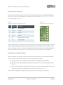
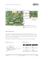
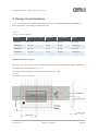
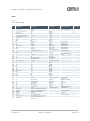
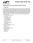
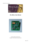
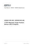
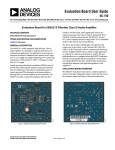
User Manual – AS5304 / AS5306 Demo Kit
AS5304 / AS5306
160-step Linear Incremental Position
Sensor with ABI output
www.ams.com
Revision 1.3 / 2012/09/24
AS5304 / AS5306 - Demo Kit User Manual
Table of Contents
1.
General Description ............................................................................................................... 2
2.
Package and Board Description ............................................................................................ 3
3.
How to get the kit running ...................................................................................................... 7
4.
Design Considerations .......................................................................................................... 8
5.
Schematics and BOM ............................................................................................................ 9
6.
Ordering Information ............................................................................................................ 11
Copyright ..................................................................................................................................... 12
Disclaimer ................................................................................................................................... 12
www.ams.com
Revision 1.3 / 09/24/12
page 1/13
AS5304 / AS5306 - Demo Kit User Manual
1. General Description
This document describes the features and operation of the AS5304/-06 Demo Kit.
The AS5304 and AS5306 are Hall-based linear incremental magnetic position sensors. They
are suitable for high resolution, contactless linear or off-axis rotary position sensing utilizing
multipole strip or ring magnets.
The AS5304 Demo-kit mounts a multi-pole strip magnet with 2mm pole length and has a
resolution of 25um per step, while the AS5306 uses a multi-pole strip magnet with 1.2mm pole
length and has a resolution of 15um per step. Both AS5304 and AS5306 have 160 -step
measurement range.
These demo kits allow the user to evaluate the AS5304/AS5306 in stand-alone mode. This can
be accomplished using connectors on the backside of the board.
For linear motion sensing, a multi-pole strip magnet is required (Figure 1). For off-axis rotary
motion sensing a multi-pole ring magnet is used (Figure 2).
Figure 1:
Arrangement with multi-pole strip magnet
www.ams.com
Figure 2:
Arrangement with multi-pole ring magnet
Revision 1.3 / 09/24/12
page 2/13
AS5304 / AS5306 - Demo Kit User Manual
2. Package and Board Description
Demo Kit Contents
The demo kit includes following items listed below in Table 1.
Table 1:
Demo Kit Contents
Pos
Item
Comment
1
AS5304/AS5306 demo board
Including mechanics
2
USB 2.0 cable
For demo board supply
3
Multipole Magnet Slider
4
Quick Start Guide
Board Description
Figure 3:
Demo board
www.ams.com
Revision 1.3 / 09/24/12
page 3/13
AS5304 / AS5306 - Demo Kit User Manual
Figure 4:
Demo board front view
A
C
(A) Incremental steps
B
(B) Calculated position
(C) Pole Pair Indicator
D
(D) Magnetic Field Strength
Indicator LED
E
(E) Multipole Magnet Slider
(F) ABI indicator LED’s
F
(G) Zero position reset button
G
Additional Information about the Position Sensor
On the back side, there are several options to connect directly to the signals of the demo board
for further evaluation of the chip.
Figure 5:
Demo board back view
A
(A) USB connector
(B) Battery connector
B
(C) Position sensor connector
C
(see Table 2 and Figure 6
for details)
D
(D) Jumper to disconnect
onboard position sensor
D
D
D
(see Figure 7 for details)
(E) Zero position reset button
E
www.ams.com
Revision 1.3 / 09/24/12
page 4/13
AS5304 / AS5306 - Demo Kit User Manual
Position Sensor Connector
The Position connector allows the user to monitor the ABI signals from the AS5304/ AS5306 as
well as to connect this demoboard to an external sensor (see below, Connection of an external
Sensor) as shown in Figure 7.
Table 2:
Position sensor connector pin out
Figure 6:
Position sensor connector
Pin
Pin Name
Description
1
GND
Ground Signal
2
A_ext
A output
3
B_ext
B output
4
I_ext
I output
5
5V
Position Sensor supply
6
AO
Analog Output
If the on-board sensor is used for the measurements the Analog Output (AO) provides an analog
output voltage that represents the Automatic Gain Control of the position sensor signal control
loop. This output is used to monitor the magnetic field strength respectively the air gap between
sensor and multipole magnet strip. For more details refer to the position sensor datasheet.
1Connection of an external Sensor
Connection of an external Sensor
With the jumpers, the onboard position sensor can be disconnected to use an external position
sensor. Follow the instructions below to use an external position sensor.
(1) Disconnect the power supply of the demoboard by unplugging the USB cable.
(2) Disconnect the onboard position sensor by removing P1, P2, P3, and P4 jumpers. See
Figure 7.
(3) As the onboard position sensor is disconnected, connect an external position sensor. For
example an AS5304 / AS5306 adapter board can be used. See Figure 7.
The AS5304 / AS5306 AB adapter board is optional and not included in the demo kit.
www.ams.com
Revision 1.3 / 09/24/12
page 5/13
AS5304 / AS5306 - Demo Kit User Manual
Figure 7:
Using an external position sensor
3
Connect the external
position sensor
(not included)
2
Unplug jumpers P1, P2, P3, P4
1
Disconnect the demo board supply
Multipole Magnet Strip
The multipole magnet strips provided in the demo kits are made by Arnold Magnetics. The
AS5304-DK-ST-1.0 has a pole pair length of 4mm and the AS5306-DK-ST-1.0 has a pole pair
length of 2.4mm. The multipole magnet strips are mounted in an aluminum/aluminium slider.
See Figure 8 and Table 3 for details.
Find additional information about magnet requirements in the position sensor datasheet.
Figure 8:
Multipole Magnet Strip
www.ams.com
Table 3:
Demo Kit Magnet
AS5304-DK-ST
AS5306-DK-ST
W
20 mm
20.4 mm
S
5 mm
5 mm
T
0.8 mm
0.8 mm
Lpp
4 mm
2.4 mm
Revision 1.3 / 09/24/12
page 6/13
AS5304 / AS5306 - Demo Kit User Manual
3. How to get the kit running
(1) Power up the demo board using the USB cable.
(2) During the start-up of the demo kit, a boot screen is shown offering basic information
about position sensor, firmware version and firmware release date. See Figure 9.
(3) After the start-up the position display is shown. The position display shows the actual
position counter value in steps and the calculated position in micrometer. Move the
multipole magnet slider. The position change is displayed. See Figure 10.
(4) Pull out the slider to remove the multi-pole magnet strip. At this point, the LEDs for
magnetic field strength and index will indicate a missing magnetic field.
(5) Fit the slider back into the mechanics. Press “Set Zero” to reset the position output.
(6) Unplug the USB cable to power down the board.
Figure 9:
Demo Kit Boot Screen
Position Sensor
Firmware Version, Release Date
Figure 10:
Demo Kit Position Display
Counter Value
Calculated Position
Magnet Pole Pair Indicator Bar
www.ams.com
Revision 1.3 / 09/24/12
page 7/13
AS5304 / AS5306 - Demo Kit User Manual
4. Design Considerations
Table 4 shows the main features and charachteristics of the AS5304A/B and AS5306A/B for
linear movement of the multi-pole magnetic strip.
Table 4:
Position sensor options
Sensor
Magnet Pole Length
Resolution
Linear Speed
Outputs
AS5304A
2.0 mm
25 µm
20 m/s
Push Pull
AS5304B
2.0 mm
25 µm
20 m/s
Open Drain
AS5306A
1.2 mm
15 µm
12 m/s
Push Pull
AS5306B
1.2 mm
15 µm
12 m/s
Open Drain
Magnet type and position
Note that the Hall sensor array is located 1.02 mm off the horizontal chip center towards the
row of pins 11…20 as shown in Figure 11.
The magnet strip should be centered over the Hall sensor array.
Figure 11:
Hall sensor array in package
www.ams.com
Revision 1.3 / 09/24/12
page 8/13
AS5304 / AS5306 - Demo Kit User Manual
5. Schematics and BOM
Schematics
The main components of the AS5304 / AS5306 demoboard are the onboard position sensor, the
quadrature counter, the main microcontroller and the display.
For easy integration of the AS5304 / AS5306, the LS7366 quadrature counter was c hoosen to
interface between position sensor and microcontroller. By using this component, the actual
position can be read out directly using the SPI interface.
The Silabs C8051F320 USB microcontroller reads the position steps and calculates the position
to show them on the LCD screen.
Find the complete schematic below for reference.
Figure 12:
Demo board schematic
www.ams.com
Revision 1.3 / 09/24/12
page 9/13
AS5304 / AS5306 - Demo Kit User Manual
BOM
Table 5:
Demo Board BOM
#
Designator
Comment
Manufacturer
Quantity
1
2
3
4
5
Displaytech 32128A-FC-BW-3
Jumper
100n
10u
1u
7
8
9
10
11
12
13
14
15
*1
*2, *3, *4, *5
C1, C3, C4, C5, C17
C2, C21
C6, C22, C23
C7, C8, C9, C10, C11,
C12, C13, C14, C15
C16, C18
C19
C20
D1
D2
D3
DS1, DS3
DS2
DS4
Displaytech
TE CONNECTIVITY
C0603
Chip_A
C0603
1
4
5
2
3
1u/16V
C0603
9
15p
NC (1u)
22u
BAS70-05
BAT54
LL4001
LED_G
LED_Y
LED3_G
MULTICOMP
FAIRCHILD
MULTICOMP
OSRAM Opto
OSRAM Opto
OSRAM Opto
2
1
1
1
1
1
2
1
1
HRS (HIROSE)
1
NC
C0603
C0603
Chip_A
SOT23
SOT23
MELF
SMD_LED
SMD_LED
SMD_LED
Tech32128aDispla
y
HDR1X4
16
J1
DisplayTech32128a
17
J2, J4
18
J3
440478-1
440478
TE CONNECTIVITY
/ AMP
19
20
21
J5
J6
J7
NC
NC (Reset_CNT)
NC (Header 2)
22
P1, P2, P3, P4
Jumper2
23
24
25
26
27
28
29
30
31
32
33
34
R1
R2
R3
R4
R5
R6
R7, R8, R9
R10
R11
R12
R13
S1
10k
68R
nc
33R
1M
47k
1k
4.7k
22k
68k
1k
SW-PB
HDR1X6
PIN1_SMD
HDR1X2
Jumper2_Horizont
al
R0603
R0603
R0603
R0603
R0603
R0603
R0603
R0603
R0603
R0603
0603_S
Multicom_MCPTF
35
U1
C8051F320
TQFP32
36
37
38
39
U2
U3
U4
U5
AS5304_06 A
LS7366R-S
AS1360-50
AS1360-30
TSSOP20
SO-G14
SOT23
SOT23
40
Y1
20MHz
HC49/4H_SMX
41
42
43
46
47
48
Mechanics
Screws
Screws
Spacer
Magnet
Transportkarton 10-TVS
49
USB Cable
Refer to mechanical drawings
M2x6mm (for Mechanics)
M3x5mm (for Spacer)
M3x6mm
AS5000 MS20-50
Use additional foam material
USB 2.0 Cable Type A ->
Type Bmini
6
www.ams.com
Footprint
Revision 1.3 / 09/24/12
2
1
1
1
1
4
MULTICOMP
SILICON
LABORATORIES
ams
US-Digital
ams
AMS
IQD FREQUENCY
PRODUCTS
NETTLEFOLDS
HARWIN
Arnold Magnetics
1
1
1
1
1
1
3
1
1
1
1
1
1
1
1
1
1
1
1
4
4
4
0.2
1
1
page 10/13
AS5304 / AS5306 - Demo Kit User Manual
6. Ordering Information
Table 6:
Ordering Information
Ordering Code
Description
comments
AS5304-DK-1.0
AS5304 Demo Kit
2.0 mm pole length / 25 µm step
AS5306-DK-1.0
AS5306 Demo Kit
1.2 mm pole length / 15 µm step
www.ams.com
Revision 1.3 / 09/24/12
page 11/13
AS5304 / AS5306 - Demo Kit User Manual
Copyright
Copyright © 1997-2012, ams AG, Tobelbader Strasse 30, 8141 Unterpremstaetten, Austria-Europe.
Trademarks Registered ®. All rights reserved. The material herein may not be reproduced, adapted, merged,
translated, stored, or used without the prior written consent of the copyright owner.
All products and companies mentioned are trademarks or registered trademarks of their respective companies.
Disclaimer
Devices sold by ams AG are covered by the warranty and patent indemnification provisions appearing in its
Term of Sale. ams AG makes no warranty, express, statutory, implied, or by description regarding the
information set forth herein or regarding the freedom of the described devices from patent infringement. ams
AG reserves the right to change specifications and prices at any time and without notice. Therefore, prior to
designing this product into a system, it is necessary to check with ams AG for current information.
This product is intended for use in normal commercial applications. Applications requiring extended
temperature range, unusual environmental requirements, or high reliability applications, such as military,
medical life-support or lifesustaining equipment are specifically not recommended without additional
processing by ams AG for each application. For shipments of less than 100 parts the manufacturing flow might
show deviations from the standard production flow, such as test flow or test location.
The information furnished here by ams AG is believed to be correct and accurate. However, ams AG shall not
be liable to recipient or any third party for any damages, including but not limited to personal injury, property
damage, loss of profits, loss of use, interruption of business or indirect, special, incidental or consequential
damages, of any kind, in connection with or arising out of the furnishing, performance or use of the technical
data herein. No obligation or liability to recipient or any third party shall arise or flow out of ams AG rendering of
technical or other services.
Contact Information
Headquarters
ams AG
Tobelbader Strasse 30
8141 Unterpremstaetten
Austria
T. +43 (0) 3136 500 0
For Sales Offices, Distributors and Representatives, please visit:
http://www.ams.com/contact
www.ams.com
Revision 1.3 / 09/24/12
page 12/13
Mouser Electronics
Authorized Distributor
Click to View Pricing, Inventory, Delivery & Lifecycle Information:
ams:
AS5304-DK-ST-1.0 AS5306-DK-1.0