1
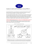
Fig. 3. Simplified diagram of the
connection between a terminal
and the twisted-pair cable. Data is
transferred in and out of the termi
nal through optocouplers to pre
vent the formation of ground loops.
Terminal Terminal
Disconnected Connected
has a series of time windows each of which is as
signed to a particular terminal. During a polling
cycle, each terminal can transmit or receive one 8-bit
ASCII character during its allotted time window.
The rate at which polling cycles occur depends on
the number of terminals in the system and, hence, on
the number of time windows in the polling cycles. For
example, with 32 terminals, polling cycles occur 26
times per second, i.e., each terminal can send and
receive at a rate of 26 characters per second. With just
one terminal, the rate is 280 per second.
Operation between the terminals and the computer
is coordinated by a sync message sent by the compu
ter at the start of a polling cycle. This message con
sists of a "1" followed by 32 "O's". Since 32 consecu
tive O's do not occur during normal traffic, the termi
nals can recognize this as the sync message. At the
same time, a counter in each terminal is reset and
starts counting time windows to determine when the
timing window for that terminal occurs. Terminals
adjust their clocks to be in phase with the sync bit of
the sync message.
A 5-bit error-checking message is appended to each
character (see Fig. 2) in the form of a cyclic redun
dancy check. This message is derived by dividing the
13-bit data message (8-bit ASCII character plus five
HP-IB control bits) by the binary polynomial xs 4- x2 +
x + 1. The remainder resulting from the division is
transmitted as the error-checking message. At the re
ceiving end, the entire 18-bit data code (13 bits plus
5-bit error-checking message] is divided by the same
polynomial and if the remainder is other than zero, an
error is indicated.
The receipt of each character at its destination (ter
minal or computer) is acknowledged by the transmis
sion of an OK code by the receiver. In the event of a
transmission error, a not OK (OK) is transmitted and the
sender retransmits the character during the next pol
ling cycle.
Transmission reliability is further enhanced by
sampling each bit eight times at the receiver. During
the eighth sample, a majority "vote" is taken on the
first seven samples to decide whether the bit is a 1 or a
0. The SYNC and START bits, however, must register
seven consecutive 1's to be declared a 1. This assures
terminal synchronization to within one-eighth of a
bit.
Data is transmitted as 5-volt, NRZ pulses at a bit rate
of 25 kHz. Propagation delays and phase delays be
tween the computer and terminal clocks could cause
delays in bits received at the computer. When the
computer interface is listening for an input, it tempo
rarily goes into an asynchronous mode and waits for
the START bit from the terminal to synchronize its re
ceiving circuits. However, the main clock continues
without change so the next time window remains syn
chronized to it and thus to the start of the polling cycle.
Fig. 4. Connection boxes may be placed anywhere on the
serial a cable. A terminal's connecting cable plugs in with a
make-before-break-operation that does not interefere with
transactions being conducted by other terminals on the cable.
22
© Copr. 1949-1998 Hewlett-Packard Co.