1
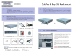
CineRAID 600/700 Series RAID Subsystem CR-R612 / CR-R616 / CR-R624 (Single Core Controller) CR-R712 / CR-R716 / CR-R724 (Dual Core Controller) Hardware Installation Guide Version 1.1 Hardware Installation Guide 10/01/2012 Copyright ©2011~2012 This guide and any accompanying software and firmware are copyrighted. No parts of this publication may be reproduced, stored on a retrieval system, or transmitted, in any form or by any means, electronic, mechanical, photocopy, recording, or otherwise, without prior written consent except for copies retained by the purchaser for backup purposes. All rights Reserved- Printed in Taiwan. Notice We make no warranties with respect to this documentation either express or implied and provide it "as it". This includes but is not limited to any implied warranties of merchantability and fitness for a particular purpose. The information in this document is subject to change without notice. We assume no responsibility for any errors that may appear in this document. The manufacturer shall not be liable for any damage, or for the loss of information resulting from the performance or use of the information contained herein Trademarks Product names used herein are for identification purposes only and may be the trademarks of their respective companies. All trademarks or registered ii Hardware Installation Guide trademarks are properties of their respective owners. iii Hardware Installation Guide R Reegguullaattoorryy iinnffoorrm maattiioonn For Europe This drive is in conformity with the EMC directive. Federal Communications Commission (FCC) Statement This equipment has been tested and found to comply with the limits for a Class A digital device, pursuant to part 15 of the FCC Rules. Those limits are designed to provide reasonable protection against harmful interference in a residential installation. This equipment generates, uses and can radiate radio frequency energy and, if not installed and used in accordance with the instructions, may cause harmful interference to radio communications. However, there is no guarantee that interference will not occur in a particular installation. If this equipment does cause harmful interference to radio or television reception, which can be determined by turning the equipment off and on, the user is encouraged to try to correct the interference by one or more of the following measures: Reorient or relocate the receiving antennas. Increase the separation between the equipment and receiver. Connect the equipment into an outlet on a circlet different from that to which the receiver is connected. Consult the dealer or an experienced radio/TV technician for help. Warning: A shielded-type power cord is required in order to meet FCC emission limits and also to prevent interference to the nearby radio and television reception. It is essential that only the supplied power cord be used. Use only shielded cables to connect I/O devices to this equipment. You are cautioned that changes or modifications not expressly approved by the party responsible for compliance could void your authority to operate the equipment. iv Hardware Installation Guide A Abboouutt TThhiiss H Haarrddw waarree IInnssttaallllaattiioonn G Guuiiddee Welcome to Hardware Installation Guide. This guide is designed to be used as step-by-step instructions for installation of your subsystem, and covers everything you need to know in learning how to operation, troubleshooting and future upgrades. For the detail about how to configure your subsystem, please refer to the Software Operation manual. S Syym mbboollss iinn TTeexxtt These symbols may be found in the text of this guide. They have the following meanings. Caution This icons indicates that failure to follow directions could result in personal injury, damage to your equipment or loss of information. Note This icon presents commentary, sidelights, or interesting points of information. Important terms, commands and programs are put in Boldface font. Screen text is given in screen font. v Hardware Installation Guide Contents ABOUT THIS HARDWARE INSTALLATION GUIDE ................................... V SYMBOLS IN TEXT ................................................................................. V CONTENTS ............................................................................................. V CHAPTER 1. INTRODUCTION ............................................................. 1 MODEL VARIATIONS ............................................................................. 1 FEATURES ............................................................................................. 2 Front Panel Overview ..................................................................... 4 Rear Panel Overview ...................................................................... 6 CHAPTER 2. INSTALLATION ............................................................. 17 UNPACKING & CHECKING THE EQUIPMENT ......................................... 17 WHAT ELSE YOU NEED ........................................................................ 18 ESD PRECAUTION ............................................................................... 18 INSTALLING HARD DISKS ..................................................................... 18 INSTALL THE CINERAID RAID SUBSYSTEM IN A RACK ...................... 20 SYSTEM CONNECTION ......................................................................... 22 CONNECTION TO CINERAID RAID SUBSYSTEM WITH SAS JBODS ..... 22 TURNING ON FOR THE FIRST TIME........................................................ 24 TURNING OFF ...................................................................................... 25 CHAPTER 3. A TROUBLE SHOOTING ............................................. 26 REPLACE THE CONTROLLER ................................................................ 26 REPLACING / UPGRADING DIMM....................................................... 27 Specifications:............................................................................... 27 CR-R600 RAID series ................................................................... 27 CR-R700 RAID series ................................................................... 28 Installing DIMM ........................................................................... 28 HOT SWAPPING TO REPLACE THE FAN MODULE.................................. 29 HOT SWAPPING TO REPLACE THE POWER MODULE ............................. 30 APPENDIX A .......................................................................................... 32 CONNECTORS .............................................................................. 32 APPENDIX B........................................................................................... 34 BATTERY BACKUP MODULE (BBM) .............................................. 34 BBM Specifications ....................................................................... 34 v Hardware Installation Guide Battery Backup Capacity ...............................................................35 Operation ......................................................................................35 Removing the Battery Backup Module ..........................................35 APPENDIX C. SPECIFICATIONS .............................................36 SPECIFICATIONS ...................................................................................36 vi Chapter 1. Introduction Chapter 1. INTRODUCTION T Thhiiss cchhaapptteerr iinnttrroodduucceess tthhee ffeeaattuurreess aanndd ccaappaabbiilliittiieess ooff C CiinneeR Raaiidd sseerriieess R RAAIID D ssuubbssyysstteem mss.. YYoouu w wiilll ffiinndd:: AA ffuulll iinnttrroodduuccttiioonn ttoo yyoouurr C CiinneeR Raaiidd R RAAIID D ssuubbssyysstteem m.. D e t a i l s o f k e y f e a t u r e s a n d s u p p l i e d a c c e s s o r i e s . Details of key features and supplied accessories. M Mooddeell V Vaarriiaattiioonnss There are twelve models in CineRAID storage subsystem series; which utilize Quad 8Gb Fibre / dual 6Gb miniSAS as Host interface per controller, each with 12, 16, or 24 device bays. . Model Name Host Interface Device bays Controller Numbers CR-R624FS/D 4 x 8Gbps FC 24 bays 1 ( Upgradeable, Up to 2) CR-R624SS/D 2x 6Gb miniSAS 24 bays 1 ( Upgradeable, Up to 2) CR-R616FS/D 4 x 8Gbps FC 16 bays 1 ( Upgradeable, Up to 2) CR-R616SS/D 2x 6Gb miniSAS 16 bays 1 ( Upgradeable, Up to 2) CR-R612FS/D 4 x 8Gbps FC 12 bays 1 ( Upgradeable, Up to 2) CR-R612SS/D 2x 6Gb miniSAS 12 bays 1 ( Upgradeable, Up to 2) CR-R724FS/D 4 x 8Gbps FC 24 bays 1 ( Upgradeable, Up to 2) CR-R724SS/D 2x 6Gb miniSAS 24 bays 1 ( Upgradeable, Up to 2) CR-R716FS/D 4 x 8Gbps FC 16 bays 1 ( Upgradeable, Up to 2) CR-R716SS/D 2x 6Gb miniSAS 16 bays 1 ( Upgradeable, Up to 2) 1 Hardware Installation Guide CR-R712FS/D 4 x 8Gbps FC 12 bays 1 ( Upgradeable, Up to 2) CR-R712SS/D 2x 6Gb miniSAS 12 bays 1( Upgradeable, Up to 2) All of CineRAID is designed to support single controller and upgradeable to two controller. CR-R(6/7)XX(F/S)(S/D) 6:Single Core, 7:Dual Core F: Fiber to Host, S:SAS to Host, S:Single Controller, D: Dual Controllers FFeeaattuurreess The CineRAID Series RAID Subsystem is designed to meet today’s high volume, performance storage requirements from rapidly changing business environment. It provides a maximum data protection and exceptional performance in a storage subsystem. Target usage ranges are set from small business to departmental and corporate server needs. The RAID SYSTEM is designed for easy integration, smooth data expansion and server migration. The CineRAID series supports the following features: 2 Quad 8Gbps Fiber / Two 6Gbps mini-SAS ports as Host 6Gbps SAS / 6Gbps SATA backplane supported. RAID Levels: 0, 1,1E, 3, 5, 6, 50, 60 & JBOD. Multiple RAID selection. Online RAID level/stripe size migration. Online Array roaming. Globe and dedicated Hot Spare Disk / Pass through Disk support. Schedule Volume Check. When connecting with JBOSs, Max 122 SAS devices. Max 128 LUNs (volume set) per controller. Online capacity expansion and RAID level migration simultaneously. Chapter 1. Introduction Online Volume Set growth Support spin down drivers when not in use to extend service life (MAID). Instant availability and background initialization. Automatic drive insertion / removal detection and rebuilding. 3 Hardware Installation Guide Understanding the CineRAID RAID subsystem Front Panel Overview LCD Module Function keys. ( ENT, ESC, Scroll up, Scroll Down ) Keys Descriptions Up Arrow To scroll upward through the menu items Down Arrow To scroll downward through the menu items (ENT ) Enter To confirm a selected item (ESC) ESC To exit a sub-menu and return to previous menu. There are three LED indicators on the front panel. Following table provides a summary of the meanings of these LED indicators: 4 Chapter 1. Introduction LED Indicator Normal Status Problem Indication Power On indicator This LED does not light up after power switched on Bright Blue Fail Indicator LED never light up Data Access Indicator LED light up as Red. Blink blue during host computer LED never flickers accessing the RAID subsystem. For additional information on using the LCD panel and keypad to configure the RAID see Software manual ”LCD Panel Configuration” on Chapter 3. Driver Bay numbering convention The enclosure bay numbering convention is shown in following figure. A bay is designed to house either single 3.5-inch hard disk drive or 2.5-inch hard disk drive. CR-R624 / CR-R724 1 5 9 13 17 21 2 6 10 14 18 22 3 7 11 15 19 23 2 6 10 14 3 7 11 15 4 8 12 16 20 24 CR-R616 / CR-R716 1 5 9 13 4 8 12 16 5 Hardware Installation Guide CR-R612 / CR-R712 1 5 9 2 6 10 3 7 11 Drive Bay Rear Panel Overview CR-R624FS/D 6 Fiber-SAS/SATA RAID SUBSYSTEM 4 8 12 Chapter 1. Introduction 16 17 18 1 3 4 5 6 7 22 CR-R624SS/D 16 23 2 15 19 20 21 9 10 11 13 24 25 26 27 SAS-SAS/SATA RAID SUBSYSTEM 17 18 1 7 22 8 12 14 23 3 8 4 12 14 2 15 19 20 21 9 10 11 13 24 25 26 27 CR-R724FS/D Fibre-SAS/SATA RAID SUBSYSTEM 7 Hardware Installation Guide CR-R724SS/D SAS-SAS/SATA RAID SUBSYSTEM 1. Controller Box 1. 2. Controller Box 2 CR-R624FS/D & CR-R724FS/D : 8 3. FC_CH_0 & LED Indicator 4. FC_CH_1 & LED Indicator 5. FC_CH_2 & LED Indicator 6. FC_CH_3 & LED Indicator LED Colors Indicate FC Green Link Chapter 1. Introduction Blue + Blink CR-R624SS/D & CR-R724SS/D : Access 3. 4. SAS CH 0 & LED Indicator SAS CH 1 & LED Indicator LED Colors Indicate SAS Green Link Blue + Blink Access 7. Raid Controller Status LED & Fault LED Indicator LED Colors Indicate Status Green + Blink Raid Controller OK Fault Red Raid Controller Fault 8. SAS Expand Port ( Reserved) 9. SAS Expand Port 1 & LED Indicator 10. SAS Expand Port 0 & LED Indicator LED Colors Indicate SAS Green Link Blue + Blink Access 11. Console 12. Terminal 13. LAN port 14. Battery back module (Option) 15. Power Switch 16. FAN failure indicator (Rear / Front) 17. FAN Module 1 18. FAN Module 1 latch 19. FAN failure indicator (Rear / Front) 20. FAN Module 2 21. FAN Module 2 latch 9 Hardware Installation Guide 22. AC inlet 1 & Latch 23. Power Module 1 24. AC inlet 2 & Latch 25. Power Module 2 26. AC inlet 3 & Latch 27. Power Module 3 10 Chapter 1. Introduction CR-R616FS/D 16 Fiber-SAS/SATA RAID SUBSYSTEM 17 18 1 14 2 15 19 34 22 23 CR-R616SS/D 16 7 8 17 18 23 CR-R716FS/D 12 9 10 11 13 24 25 SAS-SAS/SATA RAID SUBSYSTEM 1 14 2 15 19 3 22 5 6 20 21 7 8 4 20 21 12 9 10 11 13 24 25 Fiber-SAS/SATA RAID SUBSYSTEM 11 Hardware Installation Guide CR-R716SS/D SAS-SAS/SATA RAID SUBSYSTEM 1. Controller Box 1. 2. Controller Box 2 3. CR-R616FS/D & CR-R716FS/D : FC_CH_0 & LED Indicator 4. FC_CH_1 & LED Indicator 5. FC_CH_2 & LED Indicator 6. FC_CH_3 & LED Indicator LED Colors Indicate FC Green Link Blue + Blink Access CR-R616SS/D & CR-R716SS/D: 3. SAS CH 0 & LED Indicator 4. SAS CH 1 & LED Indicator LED Colors Indicate SAS Green Link Blue + Blink Access 7. Raid Controller Status LED & Fault LED Indicator LED 12 Colors Indicate Chapter 1. Introduction Status Green + Blink Raid Controller OK Fault Red Raid Controller Fault 8. SAS Expand Port ( Reserved) 9. SAS Expand Port 1 & LED Indicator 10. SAS Expand Port 0 & LED Indicator LED Colors Indicate SAS Green Link Blue + Blink Access 11. Console 12. Terminal 13. LAN port 14. Battery Backup Module 15. Power Switch 16. FAN failure indicator (Rear / Front) 17. FAN Module 1 18. FAN Module 1 latch 19. FAN failure indicator (Rear / Front) 20. FAN Module 2 21. FAN Module 2 latch 22. AC inlet 1 & Latch 23. Power Module 1 24. AC inlet 2 & Latch 25. Power Module 2 CR-R612FS/D Fiber-SAS/SATA RAID SUBSYSTEM 13 Hardware Installation Guide 20 3 4 5 6 21 16 7 8 7 8 15 18 19 9 10 11 12 13 14 1 CR-R612SS/D 20 17 3 23 2 SAS-SAS/SATA RAID SUBSYSTEM 4 21 16 17 15 18 19 9 10 11 12 13 14 1 CR-R712FS/D Fiber-SAS/SATA RAID SUBSYSTEM CR-R712SS/D SAS-SAS/SATA RAID SUBSYSTEM 14 22 22 2 23 Chapter 1. Introduction 1. Controller Box 1. 2. Controller Box 2 CR-612F8S/D & CR-712F8S/D : 3. FC_CH_0 & LED Indicator 4. FC_CH_1 & LED Indicator 5. FC_CH_2 & LED Indicator 6. FC_CH_3 & LED Indicator LED Colors Indicate FC Green Link Blue + Blink Access CR-612S6S/D & CR-712S6S/D : 3. SAS CH 0 & LED Indicator 4. SAS CH 1 & LED Indicator LED Colors Indicate SAS Green Link Blue + Blink Access CR-612S6N: 3. SAS CH 1 & LED Indicator 4. SAS CH 0 & LED Indicator LED Colors Indicate SAS Green Link Blue + Blink Access 7. Raid Controller Status LED & Fault LED Indicator LED Colors Indicate 15 Hardware Installation Guide Status Green + Blink Raid Controller OK Fault Red Raid Controller Fault 8. SAS Expand Port ( Reserved) 9. SAS Expand Port 1 & LED Indicator 10. SAS Expand Port 0 & LED Indicator LED Colors Indicate SAS Green Link Blue + Blink Access 11. Console 12. Terminal 13. LAN port 14. Battery Backup Module 15. Power Switch 16. FAN failure indicator (Rear / Front) 17. FAN Module 1 18. FAN failure indicator (Rear / Front) 19. FAN Module 2 20. AC inlet 1 & Latch 21. Power Module 1 22. AC inlet 2 & Latch 23. Power Module 2 16 Chapter 2. Installation Chapter 2. INSTALLATION This chapter presents: IInnssttrruuccttiioonnss oonn uunnppaacckkiinngg & & cchheecckkiinngg tthhee eeqquuiippm meenntt IInnssttrruuccttiioonnss oonn hhoow t o i n s t a l l H a r d d i s k d r i v e w to install Hard disk drive IInnssttrruuccttiioonnss oonn hhoow w ttoo iinnssttaallll C CiinneeR Raaiidd R RAAIID D iinn aa R Raacckk.. IInnssttrruuccttiioonnss oonn hhoow t o c o n n e c t C i n e R a i d R A I D . w to connect CineRaid RAID. U Unnppaacckkiinngg & & cchheecckkiinngg tthhee E Eqquuiippm meenntt Before unpacking the CineRAID RAID subsystem, prepare a clean, stable surface to put on the contents of CineRAID RAID shipping container. Altogether, you should find following items in the package: CineRAID Fibre to SAS/SATA RAID Subsystem : CineRAID RAID subsystem x1 CD-ROM x 1 ( Includes Hardware Installation Guide, Software operation Manual & HTTP Proxy Server utility for Web browser-based Configuration). Serial cable x1 Key for Drive Bay x 4 Power Cord x 2 (CR-612 & CR-616), Power Cord x 3 ( CR-624) Rails for Rack Mounting screws : for 2.5” disks (bag) × 1 / for 2.5” disks (bag) × 1 17 Hardware Installation Guide CineRAID SAS to SAS/SATA RAID Subsystem : CineRAID RAID subsystem x1 CD-ROM x 1 ( Includes Hardware Installation Guide, Software operation Manual & HTTP Proxy Server utility for Web browser-based Configuration). Serial cable x1 Key for Drive Bay x 4 Power Cord x 2 (CR-612 and CR-616), Power Cord x 3 ( CR-624) SAS cable ( SFF-8088 ) x 1 per controller ( For SAS model only) Rails for Rack Mounting screws : for 2.5” disks (bag) × 1 / for 2.5” disks (bag) × 1 To avoid the unmatched connector type between the Fibre HBA in the Host computer and CineRAID, CineRAID RAID doesn’t include the Fibre cable with the standard shipping. W Whhaatt eellssee yyoouu nneeeedd Hard disk drives (different RAID levels require different numbers of HDDs. Refer to Software Operation manual for more detail information. Host computer with SAS or Fiber interface. Dedicated terminal or PC with third party communication software that supports ANSI terminal emulation (required for viewing Monitor Utility) E ES SD DP Prreeccaauuttiioonn Use a suitable anti-static wrist or ankle strap and observe all conventional ESD precaution when handle CineRAID RAID’s modules and components. Avoid contact with backplane components and module connectors. IInnssttaalllliinngg hhaarrdd ddiisskkss The CineRAID RAID series includes 12/16/24 hot swappable drive bays. The 18 Chapter 2. Installation following sections describe how to install disks into CineRAID RAID subsystems. Loading 2.5” Hard Disk to the drive bay. 1. Put 2.5 HDD into the bay. 2. Fasten all 4 screws to mount HDD in the bay and make sure the HDD is properly tightened. Loading 3.5” Hard Disk to the drive bay. 1. Put 3.5 HDD into the bay. 2. Fasten all 4 screws to mount HDD in the bay and make sure the HDD is properly tightened. Place drive bays back into the system 1. Slide in drive bay; make sure the handle is open fully. 2. Close the handle to engage the drive bay into the slot. The hard drives in a RAID array should match in size and speed. All drives in any array should be identical models with the same firmware versions. RAID arrays can use any size drive; however the smallest drive will determine the size of the array. 1. Only use the screws offered with CineRAID RAID subsystem. Longer screws might cause the drive damage. 2. All the drive bays ( with or without hard drive) must be placed in the CineRAID subsystem. CineRAID’s cooling system is designed with full of drive bays. Missing drive bays might cause the subsystem damage. 19 Hardware Installation Guide IInnssttaallll TThhee C CiinneeR RA AIID D R RA AIID D ssuubbssyysstteem m iinn aa R Raacckk You are shipped one rackmount kit for each CineRAID subsystem that you intend to rackmount. CineRAID subsystem is designed for installation into a industry-standard 19-inch rackmount cabinet. Following the use of this section for installing the CineRAID subsystem into a Rack Install the Slide Rails 1. Combine Left slide rail and rear slide rail. 2. Measure the depth of the rack enclosure, then fasten 4 of P4*8M screws into M4 Locking nuts to fix the length. 3. Use T5*8M screws and PW14 washer to install the left slide on Front and rear Posts of Rack as Figure 1. 4. Repeat procedure 1 ~ 3 to install the right Slide into the Rack. Figure 1. Place the CineRAID Subsystem into the rack 20 Chapter 2. Installation 1. Lift the subsystem enclosure and slide it slowly and gently along the slide rail into the rack as Figure 2. Figure 2. 2. Fasten two M5 screws through the chassis ears in the front side of the chassis to secure the CineRAID subsystem in the rack as Figure 3. Figure 3. The CineRAID subsystem is heavy, two person are required to move the system in the procedure. 21 Hardware Installation Guide S Syysstteem mC Coonnnneeccttiioonn Connect all cables and power cord as shown below : Cable CineRAID RAID Device Purpose Serial Cable Terminal Port ANSI Terminal or a PC with Configuration Utility Terminal emulator. Serial Cable Console Port ANSI Terminal or a PC with Debug port, to check and Terminal emulator. monitoring all of status of RAID subsystem. Fibre cable / Primary FC-AL/SAS Mini SAS Cable Secondly FC-AL / SAS FC-AL / SAS HBA of Host Host interface between computer RAID and Host computer Power Cord Power inlet A/C power outlet A/C power input RJ 45 Cable Ethernet Port Switch or HUB Connect to Internet. Mini SAS Cable SAS Expander Port Raid System Connect to SAS Expander CineRAID RAID subsystem with redundancy controllers supporting require the installation of MPIO ( Multi pathing I/O ) drivers for use with different operating systems. For more detail information, please check Chapter 6 of “Software Operation Manual”. C Coonnnneeccttiioonn ttoo C CiinneeR RA AIID D R RA AIID D ssuubbssyysstteem m w wiitthh S SA AS S JJB BO OD Dss There are many topologies of SAS JBOD with CineRAID RAID subsystems. Ways to implement are as below: One SAS Raid subsystem with one SAS JBOD 22 Chapter 2. Installation 16Bays Fibre RAID 16bays JBOD One SAS Raid subsystem with more SAS JBODs 16Bays Fibre RAID 16bays JBOD 16bays JBOD 16bays JBOD 16bays JBOD It supports up to four tiers and 122 drives. One RAID Set supports up to 32 HDDs One SAS Raid subsystem supports up to 122 Volumes One SAS Raid subsystem supports up to 122 SAS devices 23 Hardware Installation Guide There are four tiers within JBOD topology as above: First tier is a RAID System. Second tier is a SAS JBOD with a SAS CH0 on it. Connecting SAS CH0 to SAS exp. Port on RAID System via a Mini SAS to Mini SAS Cable. Third tier could be two SAS JBODs with a SAS CH0 port individually. One is connected to the SAS EXP. Port on the second tier SAS JBOD via a Mini SAS to Mini SAS Cable. Another is connected to the SAS CH1/E Port on the second tier SAS JBOD Fourth tier is a SAS JBOD with a SAS CH0 on it. Connecting SAS CH0 to SAS exp. Port on third tier SAS JBOD via a Mini SAS to Mini SAS Cable. 1. CineRAID RAID subsystem do not require the installation of different drivers for use with different operating systems. CineRAID RAID is independent and transparent to the host operating system. 2. It is often recommended to install the hard drive with same brand, model no., interface and capacity in this RAID subsystem. 3. Please do not install SAS and SATA hard drives at the same time, as these hard drives spin at different speed and may lead to compatible issues or performance decline. 4. RAID members need to be included at the same enclosure that means you need to create array in the same enclosure. RAID members across two or more enclosures would get some risks (for example: if mini-SAS cable get problem, more RAID members will be lost, volume sets belong to this Array may be failed. Shutdown RAID and JBOD to fix problem, after that, turn on JBOD and RAID system again and controller will get array back, but in some special case maybe it can’t get array back) TTuurrnniinngg oonn ffoorr tthhee ffiirrsstt ttiim mee When cabling is completed, RAID SYSTEM can be turned on. This should be done in the following order: 1. First turn on the power switch of JBODs. 2. Then turn on the power switch of RAID SYSTEM. 24 Chapter 2. Installation 3. Power on and boot the host computer(s) When RAID SYSTEM is running, you are ready to configure one or more RAID arrays. You have the following options: 1. Turn to Chapter 3 of “Software Operation Manual” to perform a quick setup of a single RAID array using the control panel. 2. Turn to Chapter 6 of “Software Operation Manual” to access the Monitor Utility. Once the Monitor Utility is accessed, you can perform a Quick Setup or complete configuration with Monitor Utility. 3. Turn to Chapter 5 of “Software Operation Manual” to perform a full configuration using the web browser. TTuurrnniinngg ooffff When turning off RAID SYSTEM, users are advised to first shut down the server, then power off RAID SYSTEM. 25 Hardware Installation Guide Chapter 3. A TROUBLE SHOOTING This chapter contains trouble shooting procedures and suggestions to minimize their impact on the CineRAID RAID operation : IInnssttrruuccttiioonnss oonn hhoow w ttoo rreeppllaaccee tthhee ccoom mppoonneennttss ooff C i n e R A I D R A I D s u b s y s t e m . CineRAID RAID subsystem. If the fault LED on the front panel and LCD of CineRAID RAID lights red and LCD displays an error message, or if CineRAID RAID’s Internet manager indicates a fault, determine the reason for this alert immediately. Examine the component LEDs to see if any indicates a fault, and then replace it as soon as possible. R Reeppllaaccee tthhee C Coonnttrroolllleerr Read the replacing notices earlier in this chapter before proceeding with replacement. This section provides instructions for the removal and installation of the RAID controller components indicated in the figure below. This section is for the reference of engineers. End users should not need to replace or remove components. Removing the controller from CineRAID 16bays and 24bays RAID : In order to access controller box, turn anti-clock wise to release two thumb screws, then use the eject bar to remove controller box. 26 Chapter 3. Trouble Shooting Removing the controller from CineRAID 12bays RAID : In order to access controller box, 3. 1. Turn anti-clock wise to release the thumb 2. 1. Screws. 2. Push down the use eject bar to remove The controller box. Installing the controller into CineRAID RAID: Reverse the procedure of “removing the controller” to install the controller into CineRAID RAID. Then according to “Appendix C. Configuration table” on “Soft Operation Manual” to reconfigure your RAID R Reeppllaacciinngg // U Uppggrraaddiinngg D DIIM MM M CineRAID RAID CR-600 series are normally supplied with 1GB cache memory installed, CineRAID RAID CR-700 series are normally supplied with 1GB cache memory installed. There's no set formula to determine how much cache memory to use, but as a general rule, a workstation, with mostly very large files, such as for audio or video editing and playback, graphics or CAD files, can benefit from a large cache. File servers, with multiple random access of varying file size, generally have little or no performance improvement with additional cache. Specifications: CR-600 RAID series Type Parity (ECC) 240-pin DDR-II DIMM module (DDR II-800Mhz) ECC, with Register. With parity for data security. 27 Hardware Installation Guide Size From 512MB, 1GB, 2GB & 4GB CR-700 RAID series 240-pin DDR-III DIMM module (DDR III-1333Mhz) ECC, with Register. Parity (ECC) With parity for data security. Size From 1GB, 2GB, 4GB & 8GB ( Dual Rank). Type Installing DIMM To install a DIMM, ensure the system power is off and disconnected. Then: 1. Turn anti- lock wise to release two thumb screws, then use the eject bar to remove controller box, and then open the cover. 2. Remove the BBM module. 3. Insert a memory card at a 45-degree angle into the memory card socket so that the gold teeth of the card are no longer visible. 4. Press the card down firmly until the latches lock it into place. 28 Chapter 3. Trouble Shooting 1. Before starting any kind of hardware installation, please ensure that all power switches have been turned off and all power cords disconnected to prevent personal injury and damage to the hardware. 2. Use screws provided with CineRAID system only. Longer or shorter screws may cause electric shorting or un-proper installed. 3. Static electricity can damage electronic components. To guard against such damage: Work in a static-free environment Wear a grounded anti-static wrist strap Store uninstalled components in anti-static bags Handle PCBs by their edges and avoid touching chips and connectors. H Hoott S Sw waappppiinngg ttoo rreeppllaaccee tthhee FFaann M Moodduullee This section provides instructions for the removal and installation of the Fan Module indicated in the figure below. Removing the Fan Module from CineRAID 16bays and 24bays subsystems : Remove the Fan modules by slide the release button left and pull the module out Pull out of system. push Replace the Fan in Fan module 1. There are two failure LEDs on the rear of Fan module. Check which LED lights to yellow. 2. Remove the Fan modules by anti-clock wise to release the thumb screw then slide it back and lifting off. 3. Release the screw to remove the defect fan. 4. Insert the spare Fan and fasten the 29 Hardware Installation Guide screw. Removing the Fan Module from CineRAID 12bays RAID subsystems : In order to access controller box, 2. 1. 1. Turn anti-clock wise to release the thumb Screws. 2. Push down then use eject bar to remove controller box. 3. Remove the Fan modules by pull the module out of system. Replace the Fan in Fan module 5. There are two failure LEDs on the rear of Fan module. Check which LED lights to yellow. 6. Remove the Fan modules by anti-clock wise to release the thumb screw then slide it back and lifting off. 7. Release the screw to remove the defect fan. 8. Insert the spare Fan and fasten the screw. H Hoott S Sw waappppiinngg ttoo rreeppllaaccee tthhee P Poow weerr M Moodduullee This section provides instructions for the removal and installation of the Power Module indicated in the figure below. 30 Chapter 3. Trouble Shooting Removing the Power Module Unscrew the thumb fastener, then push right the release button, slide it back and lifting off. Installing the CineRAID: Power module into Insert a Power module then fasten the screw. The Power indicator will turn bright “Green” to indicate it has powered on 31 Hardware Installation Guide Appendix A C o n ne c t o r s Ethernet RJ-45 Connector 1. 8. Pin# Signal Name 1 TX+ 2 TX- 3 RX+ 4 NC 5 NC 6 RX- 7 NC 8 NC Fiber SFP Pin# Signal Name 1 3 VEFT TFAULT TDIS 4 MOD_DEF(2) 5 MOD_DEF(1) 6 MOD_DEF(0) 7 Rate Select 8 LOS 9 11 VEER VEER VEER 12 RD- 2 10 13 RD+ 14 17 VEER VCCR VCCT VEET 18 TD+ 15 16 32 19 TD- 20 VEET Appendix A. Connectors RJ-11 Pin# 1 2 3 4 5 Signal Pin# Signal NC 6 NC GND RX TX CTS Pin# A1 A2 A3 A4 A5 A6 A7 A8 A9 A10 A11 A12 A13 Signal GND RX0+ RX0GND RX1+ RX1GND RX2+ RX2GND RX3+ RX3GND miniSAS (SFF-8088) Pin# B1 B2 B3 B4 B5 B6 B7 B8 B9 B10 B11 B12 B13 Signal GND TX0TX0+ GND TX1TX1+ GND TX2TX2+ GND TX3TX3+ GND 33 Hardware Installation Guide Appendix B Battery Backup Module (BBM) The external RAID controller operates using cache memory .The battery Backup Module is an add-on module that provides power to the external RAID controller cache memory in the event of a power failure. The Battery Backup Module monitors the write back cache on the external RAID controller, and provides power to the cache memory if it contains data not yet written to the hard drives when power failure occurs. BBM Specifications Mechanical Module Dimension (W x H x D) : 50 x 5 x 147 mm BBM Connector 3 x Pins Connector Input Voltage +3.6 VDC On Board Battery Capacity 3000MAH (3*1000MAH) 34 Install the BBM and fasten 4 screws.on BBM carrier. Plug in the BBM’s connector into socket on carrier Appendix B. Battery Back up Module Plug the BBM carrier into the controller and fasten the thumb screws. Battery Backup Capacity Battery backup capacity is defined as the maximum duration of a power failure for which data in the cache memory can be maintained by the battery. The BBM’s backup capacity varied with the memory chips that installed on the external RAID controller Capacity Memory Type Battery (Hours) 512MB Memory Normal 160 1GB Memory Normal 105 Backup duration Operation Battery conditioning is automatic. There are no manual procedures for battery conditioning or preconditioning to be performed by the user. Battery bad a tendency to “remember” its capacity. In order to make sure of all the capacity of your battery cells, allow the battery cell to be fully charged when installed for the first time. The first time charge of battery cells takes about 24 hours to complete. Removing the Battery Backup Module The battery module will need to be removed for one of the following reason: Disconnect battery module if there is a long storage period before deployment The LI-ION battery will no longer accept a charge properly. 35 Hardware Installation Guide Appendix C. Specifications Specifications CineRAID CR-6 RAID Series CR-R624 Model Controller Number CRR624FS/D CRR624SS/D CR-R616 CRR16FS/D Up to 2 CRR616SS/D CRR612FS/D Up to 2 CRR612SS/D Up to 2 800Mhz RAID-On-Chip Storage Processor. RAID Architecture CR-R612 Up to 4GB DDR2-800 SDRAM on one DIMM socket with Advanced PCI-Express 2.0 x8 bus architecture ECC protection. Battery backup modules ready (Optional). Write-Through or Write-back cache mode support. Real time clock support. NVRAM for RAID configuration and transaction log. *RAID Levels: 0, 1,1E, 3, 5, 6, 50, 60 & JBOD. RAID Features System Type Host Interface *Online array roaming. *Multiple RAID selection. *Automatic drive insertion / removal detection and rebuilding. *Offline RAID set *Online capacity expansion and RAID level migration simultaneously. *Online volume set growth. *Support spin down drivers for idle disk to extend service life ( MAID ). *Instant availability and background initialization. *Great than 2TB per volume set ( 64-bit LBA support) *Supports up to 122 SAS devices. *Support Global Hot Spare and local Hot Spare disk *Max 128 LUNs ( volume sets ) per RAID set *Disk Scrubbing / array verify scheduling for automatic repair of all configured RAID sets. *Login record in the event log with IP address and service (http, telnet, and serial) 4U Rackmount Dual Quad 8Gb miniSAS FC ports per (4x6Gb) ports controller per controller 36 3U Rackmount Dual Quad 8Gb FC miniSAS ports per (4x6Gb) ports controller per controller 24 x 6Gb SAS / 6Gb SATA drives Disk Interface *Online RAID level / stripe size migration. 16 x 6Gb SAS / 6Gb SATA drives 2U Rackmount Quad 8Gb FC ports per controller Dual miniSAS (4x6Gb) ports per controller 12 x 6Gb SAS / 6Gb SATA drives Dual downstream miniSAS (4x6Gb) expand ports per controller Appendix C. Specification CR-624 Model RAID Management CR-616 CR-612 CRCRCRCRCRCRR624FS/D R624SS/D R624FS/D R624SS/D R624FS/D R624SS/D Firmware-embedded Web browser-based RAID manager via built-in 10/100 Ethernet. Firmware-embedded manager through front LCD control panel. Firmware-embedded manager via RS-232 port. Field-upgradeable firmware in flash ROM. All system status can be monitored by firmware-embedded Web browser-based RAID manager. Monitoring Indicators / Firmware-embedded SNMP agent allows the remote to monitor events with no SNMP agent required. System status indication through LCD, LED and alarm buzzer. All system events can be sent to multiple user alerts via e-mails. ( SMTP) *Single controller: OS independent and transparent Operating System Power Supply Electrical *Redundant controller: MPIO (Multipath I/O) driver required Redundant by three 500W / 80 Plus energy-efficient power modules with PFC and, load sharing and cable-less design. Redundant by dual 500W / 80 Plus energy-efficient power modules with PFC, load sharing and cable-less design. Redundant by dual 500W / 80 Plus energy-efficient power modules with PFC. load sharing and cable-less design. AC Voltage 100-240 VAC / AC Frequency 50-60Hz Operating temperature: 5 to 35 degree C. Temperature Non operating temperature: -40 to 60 degree C. Relative Humidity Dimension Weight 20% to 80% non-condensing 446.5mm(W) x 517mm(D) x 4U S6S/S6N/F8S : 34KGS; F8D/ S6D: 36.5KGS 446.5mm(W) x 517mm(D) x 3U S6S/S6N/F8S : 20KGS ; S6D/F8D : 22.5KGS 446.5mm(W) x 517mm(D) x 2U S6S/S6N/F8S : 17KGS ; S6D/F8D : 20KGS 37 Hardware Installation Guide CineRAID CR-7 RAID Series CR-R724 CR-R716 CR-R712 Model CR- R724FS/D Controller Number CR-R724SS/D Up to 2 CR- R716FS/D CR- R716SS/D Up to 2 CR- R712SS/D Up to 2 Dual core RAID-on-Chip (ROC) 800MHz processor RAID Architecture CR- R712FS/D Up to 8GB DDR3-1333 SDRAM on one DIMM socket with Advanced PCI-Express 3.0 bus architecture ECC protection. Battery backup modules ready (Optional). Write-Through or Write-back cache mode support. Real time clock support. NVRAM for RAID configuration and transaction log. *RAID Levels: 0, 1,1E, 3, 5, 6, 50, 60 & JBOD. RAID Features System Type Host Interface Disk Interface 38 *Online array roaming. *Multiple RAID selection. *Automatic drive insertion / removal detection and rebuilding. *Offline RAID set *Online capacity expansion and RAID level migration simultaneously. *Online volume set growth. *Support spin down drivers for idle disk to extend service life ( MAID ). *Instant availability and background initialization. *Great than 2TB per volume set ( 64-bit LBA support) *Supports up to 122 SAS devices. *Support Global Hot Spare and local Hot Spare disk *Max 128 LUNs ( volume sets ) per RAID set *Disk Scrubbing / array verify scheduling for automatic repair of all configured RAID sets. *Login record in the event log with IP address and service (http, telnet, and serial) 4U Rackmount Quad 8Gb FC ports per controller Dual miniSAS (4x6Gb) ports per controller 24 x 6Gb SAS / 6Gb SATA drives *Online RAID level / stripe size migration. 3U Rackmount Quad 8Gb FC ports per controller Dual miniSAS (4x6Gb) ports per controller 16 x 6Gb SAS / 6Gb SATA drives 2U Rackmount Quad 8Gb FC ports per controller Dual miniSAS (4x6Gb) ports per controller 12 x 6Gb SAS / 6Gb SATA drives Dual downstream miniSAS (4x6Gb) expand ports per controller Appendix C. Specification CR-R724 CR-R716 CR-R712 Model CR- R724FS/D CR-R724SS/D CR- R716FS/D CR- R724FS/D CR-R724SS/D CR- R716FS/D Firmware-embedded Web browser-based RAID manager via built-in 10/100 Ethernet. RAID Management Firmware-embedded manager through front LCD control panel. Firmware-embedded manager via RS-232 port. Field-upgradeable firmware in flash ROM. All system status can be monitored by firmware-embedded Web browser-based RAID manager. Monitoring Indicators / Firmware-embedded SNMP agent allows the remote to monitor events with no SNMP agent required. System status indication through LCD, LED and alarm buzzer. All system events can be sent to multiple user alerts via e-mails. ( SMTP) *Single controller: OS independent and transparent Operating System Power Supply Electrical *Redundant controller: MPIO (Multipath I/O) driver required Redundant by three 500W / 80 Plus energy-efficient power modules with PFC and, load sharing and cable-less design. Redundant by dual 500W / 80 Plus energy-efficient power modules with PFC, load sharing and cable-less design. Redundant by dual 500W / 80 Plus energy-efficient power modules with PFC. load sharing and cable-less design. AC Voltage 100-240 VAC / AC Frequency 50-60Hz Operating temperature: 5 to 35 degree C. Temperature Non operating temperature: -40 to 60 degree C. Relative Humidity Dimension Weight 20% to 80% non-condensing 446.5mm(W) x 517mm(D) x 4U 446.5mm(W) x 517mm(D) x 3U 446.5mm(W) x 517mm(D) x 2U S6S//F8S : 34KGS; F8D/ S6D: 36.5KGS S6S//F8S : 20KGS ; S6D/F8D : 22.5KGS S6S/S/F8S : 17KGS ; S6D/F8D : 20KGS Specifications subject to change without notice. 39