1
2–3
Installation and Setup
The H2 Series EBC DIP Switch
The H2–EBC(100)
& H2–EBC–F
DIP Switch
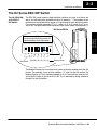
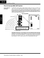
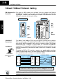
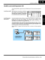
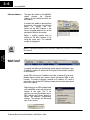
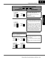
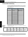
The EBC DIP switch contains eight individual switches, but only six of these are
active. You will find that the printed circuit board is labeled 0 – 7. The numbers on the
printed circuit board indicate the power of 2 represented by each individual switch.
For example, switch 0 represents 20 (or 1), switch 1 is 21 (or 2), switch 2 is 22 (or 4),
and so on. The figure below shows the binary value of each switch in parentheses ( ).
H2 Series EBCs
Installation
and Setup
The numbers (0–7) printed on the
circuit board indicate the power of 2
represented by each slide switch.
ON
7
Not Used
6
5 4
. .
25 24
. .
(32)(16)
3.
23
.
(8)
2.
22
.
(4)
1.
21
.
(2)
0
.
20
.
(1)
Binary Value
Ethernet Base Controller Modules, 3rd Edition, 11/04
Installation and
Safety Guidelines
The Module ID equals the sum of the binary values of the slide switches set in the ON
position. For example, if you set slide switches 1, 2, and 3 to the ON position, the
Module ID will be 14. This is found by adding 8+4+2=14. The maximum value you can
set on the DIP switch is 32+16+8+4+2+1=63. This is achieved by setting switches 0
through 5 to the ON position.