1
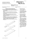
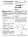
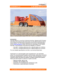
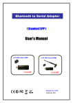
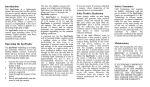
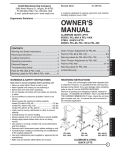
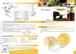
Vestil Manufacturing Company
2999 N. Wayne Street, P.O. Box 507
Angola, IN 46703 USA
Phone (260) 665-7586 • Fax (260) 665-1339
[email protected] • www.vestil.com
Revised 04-03
A company dedicated to solving ergonomic and material
handling problems since 1955.
OWNER'S
MANUAL
TIE ROD, WALL & FLOOR MOUNTED JIBS
Model JIB-HC, JIB-LC, JIB-FM
Contents
Warnings and Safety Instructions .................... 1
Receiving Instructions ..................................... 1
Warranty .......................................................... 1
Inspection Instructions ..................................... 2
Installation Instructions for Tie Rod Jibs .......... 3
Installation Instructions for Wall Jibs ................ 4
Installation Instructions for Floor Jibs ............ 5-8
Warning Labels ................................................ 9
Material Safety Data Sheets ...................... 10-11
Material Handling Problem Solvers ................ 12
WARRANTY
This product is warranted for 90 DAYS from
Read owner's manual completely before operating unit!
date of purchase to be free of manufacturing defects
• Keep clear when operating.
in material and workmanship. The manufacturer's
• Never go under unit if there is weight on unit.
obligation hereunder is limited to repairing such
• Remove weight before working on unit.
products during the warranty period, provided the
• Always inspect unit before each use.
product is sent prepaid back to the factory.
• Never use if unit is damaged.
This warranty does not cover normal wear of
• Never lift more than the rated capacity.
parts or damage resulting from any of the following:
• Never mount unit near electrical lines.
• When mounting this unit be sure supporting surface negligent use or misuse of the product, use or
application contrary to
is sufficient.
• Make sure all operator safety labels are in place. installation instructions, or disassembly, repair or
alteration by any person prior to authorization from
a factory representative.
RECEIVING INSTRUCTIONS
Every unit is thoroughly tested and inspected
prior to shipment. However, it is possible that the
unit may incur damage during transit. If you see
damage when unloading make a note of it on the
JIB-FM
SHIPPER RECEIVER.
Remove all packing and strapping material,
inspect for damage. IF DAMAGE IS EVIDENT,
FILE A CLAIM WITH THE CARRIER
JIB-HC
IMMEDIATELY! Also, check the platform size, type
of power unit, etc., to see that the unit is correct for
the intended application.
JIB-LC
WARNINGS & SAFETY INSTRUCTIONS
TIE ROD, WALL & FLOOR MOUNTED JIBS
1
INSPECTION INSTRUCTIONS
Per OSHA Regulations 1910.179 all gantry cranes/jibs should have an:
1910.179(j)(1)(i) Initial inspection - Prior to initial use all new and altered cranes shall be inspected to insure compliance.
Besides that, for gantry cranes in regular service, there are two general classifications of inspections based upon the
intervals at which the inspection should be performed. The intervals in turn are dependent upon the nature of the critical
components of the crane and the degree of their exposure to wear, deterioration, or malfunction. The two general
classifications are herein designated as "frequent" and "periodic" with respective intervals between inspections as defined
below:
1910.179(j)(1)(ii)(a)
Frequent inspection - Daily to monthly intervals.
1910.179(j)(1)(ii)(b)
Periodic inspection - 1 to 12 month intervals.
1910.179(j)(2) Frequent Inspection
The following items shall be inspected for defects at intervals as defined above or as specifically indicated, including
observation during operation for any defects which might appear between regular inspections. All deficiencies such as
listed shall be carefully examined and determination made as to whether they constitute a safety hazard:
•
All functional operating mechanisms for maladjustment interfering with proper operation. Daily.
•
Hooks with deformation or cracks. Visual inspection daily; monthly inspection with a certification record which
includes the date of inspection, the signature of the person who performed the inspection and the serial number, or
other identifier, of the hook inspected.
•
Hoist chains, including end connections, for excessive wear, twist, distorted links interfering with proper function, or
stretch beyond manufacturer's recommendations. Visual inspection daily; monthly inspection with a certification
record which includes the date of inspection, the signature of the person who performed the inspection and an
identifier of the chain which was inspected.
•
All functional operating mechanisms for excessive wear of components.
•
Rope reeving for noncompliance with manufacturer's recommendation.
1910.179(j)(3) Periodic Inspection
Complete inspections of the crane shall be performed at intervals as generally defined above, depending upon its activity,
severity of service, and environment, or as specifically indicated below. These inspections shall include the requirements
of the frequent inspection stated above and in addition, the following items. All deficiencies such as listed shall be
carefully examined and determination made as to whether they constitute a safety hazard:
•
Deformed, cracked, or corroded members.
•
Loose bolts or rivets.
•
Cracked or worn sheaves and drums.
•
Worn, cracked or distorted parts such as pins, bearings, shafts, gears, rollers, locking and clamping devices.
•
Excessive wear on brake system parts, linings, pawls, and ratchets.
•
Load, wind, and other indicators over their full range, for any significant inaccuracies.
•
Gasoline, diesel, electric, or other powerplants for improper performance or noncompliance with applicable safety
requirements. (IF APPLICABLE)
•
Excessive wear of chain drive sprockets and excessive chain stretch.
2
TIE ROD JIB (FOR HIGH CEILINGS)
Model JIB-HC-3-89, JIB-HC-6-89, JIB-HC-10-89 & JIB-HC-20-89
1-11/16"
1-11/16"
BOOM ASSEMBLY, UPPER SUPPORT ASSEMBLY & TIE
ROD ASSEMBLY FOR LOW CEILING JIBS
(SHIPPED IN 3 SECTIONS)
2
1) Drill holes at desired height on a steel column using the
dimensions as shown. Make sure that the holes are centered
on the column.
2) Bolt the mounting brackets to the column with suitable
fasteners.
2
CENTER
37-5/8"
WARNING! This equipment
is not designed for and
should not be supporting or
transporting personnel.
2
2
COLUMN
13/16" DRILL THROUGH
1ST FLANGE 12 PLACES
LOW CEILING JIB CRANE IS SHIPPED IN 2 SECTIONS,
FRAME ASSEMBLY & PIVOT BRACKETS
UPPER SUPPORT
ASSEMBLY
TIE ROD
ASSEMBLY
H
J
G
B
C
D
1
BOOM
ASSEMBLY
1) After brackets are mounted, (28-126-050) place thrust
bearing (A) under bearing boss (B).
2) Align bearing boss (B) with the holes inside the mounting
bracket (C) on the column.
3) Place rod (D) through the holes of the mounting bracket
and the bearing boss (B).
4) Place 1-1/8 flat washers (E) on both ends of the rod (D).
5) Tighten both ends of the rod with 1-1/8" nuts (F), be sure
that there is even amount of threads on both ends of the rod
(D). Allow a 1/4" gap between the bearing boss and the top
of the bracket.
6) Repeat steps 1-5 for the bottom assembly.
7) Align the pin holes of one yoke (H) to the pivot yoke brace
(J) and secure the clevis pin and cotter pin
8) Adjust yoke ends and tie rod (G) evenly to plump and level
the beam.
9) Then secure the other yoke (I) to the I-Beam with a clevis
pin and cotter pin
A
E
F
3
WALL JIB (FOR LOW CEILINGS)
Model JIB-LC-3-92, JIB-LC-6-92, JIB-LC-10-92 & JIB-LC-20-92
1-11/16"
LOW CEILING JIB CRANE IS SHIPPED IN 2 SECTIONS,
FRAME ASSEMBLY & PIVOT BRACKETS
1-11/16"
1) Drill holes at desired height on a steel column using the
dimensions as shown. Make sure that the holes are centered
on the column.
2) Bolt the mounting brackets to the column with suitable
fasteners.
2
2
50-1/4"
CENTER
COLUMN
2
WARNING! This equipment
is not designed for and
should not be supporting or
transporting personnel.
2
13/16" DRILL
THROUGH 1ST
FLANGE 12 PLACES
FRAME ASSEMBLY
LOW CEILING JIB CRANE IS SHIPPED IN 2 SECTIONS,
FRAME ASSEMBLY & PIVOT BRACKETS
B
PIVOT
BRACKETS
C
D
A
E
F
4
1) After brackets are mounted, (28-126-012) place thrust
bearing (A) under bearing boss (B).
2) Align bearing boss (B) with the holes inside the mounting
bracket (C) on the column.
3) Place rod (D) through the holes of the mounting bracket
and the bearing boss (B).
4) Place 1-1/8 flat washers (E) on both ends of the rod (D).
5) Tighten both ends of the rod with 1-1/8" nuts (F), be sure
that there is even amount of threads on both ends of the rod
(D). Allow a 1/4" gap between.
6) Repeat steps 1-5 for the bottom assembly.
7) Shim between pivot bracket and mounting beam to level jib
boom.
FLOOR MOUNTED JIBS
Model JIB-FM-3-80
ROLLER
BEARING
CONE
MAST
ASSEMBLY
LOCKING
NUTS
LEVELING
NUTS
4
1
18
15
FOUNDATION
JIB CRANE IS SHIPPED IN 3 SECTIONS, HEAD ASSEMBLY,
BOOM ASSEMBLY, MAST ASSEMBLY, AND A BOX
CONTAINING BOLTS AND INSTRUCTIONS
1) After foundation has hardened with anchor bolts set, install
leveling nuts (jam nuts) on anchor bolts and level across
nuts. Then fill center of bolt patter to top of leveling nuts, with
grout (Morta Mix).
2) Set mast into position on leveling nuts, install locking nuts
on top of anchor bolts and base plate.
3) Plumb the mast at 90° increments. Using the leveling nuts
to plumb.
4) Liberally grease the roller thrust bearing. The cone has
been installed at the factory inside to head assembly.
5) Lower head assembly onto mast assembly. Use care not to
damage roller thrust bearing.
6) Raise boom assembly onto head assembly. Attach with
4 - ASTM A325, 3/4 dia. bolts supplied.
7) After jib crane is operating satisfactorily set final grout under
base plate and let harden before placing jib crane into
service.
42
BOOM ASSEMBLY
HEAD
ASSEMBLY
42
15
MAST
ASSEMBLY
42
15
FOUNDATION
4
RECOMMENDED FOUNDATION CONCRETE
FOUNDATION REQUIREMENTS ARE BASED ON A
SOIL PRESSURE OF 2500 LBS. PER SQUARE FOOT
3000 LBS. PER SQUARE INCH COMPRESSIVE
CONCRETE (5 BAG MIX TO ONE YARD OF CONCRETE)
SPECIFICATIONS
• 300 lbs. Capacity
• 750 lbs. Overall Weight
ANCHOR BOLTS
7/8" Diameter with J-Hook
5" Above Concrete Surface
15" Deep
18
15
42
REINFORCING BARS
- o 3/4 ROD ON BOTTOM
- o 5/8 ROD ON TOP
ON APPROX. 12" CTRS.
BOTH SIDES
WARNING! This equipment
is not designed for and
should not be supporting or
transporting personnel.
5
FLOOR MOUNTED JIBS
Model JIB-FM-6-80
ROLLER
BEARING
CONE
MAST
ASSEMBLY
LOCKING
NUTS
LEVELING
NUTS
4
1
24
19
FOUNDATION
JIB CRANE IS SHIPPED IN 3 SECTIONS, HEAD ASSEMBLY,
BOOM ASSEMBLY, MAST ASSEMBLY, AND A BOX
CONTAINING BOLTS AND INSTRUCTIONS
1) After foundation has hardened with anchor bolts set, install
leveling nuts (jam nuts) on anchor bolts and level across
nuts. Then fill center of bolt patter to top of leveling nuts, with
grout (Morta Mix).
2) Set mast into position on leveling nuts, install locking nuts
on top of anchor bolts and base plate.
3) Plumb the mast at 90° increments. Using the leveling nuts
to plumb.
4) Liberally grease the roller thrust bearing. The cone has
been installed at the factory inside to head assembly.
5) Lower head assembly onto mast assembly. Use care not to
damage roller thrust bearing.
6) Raise boom assembly onto head assembly. Attach with
4 - ASTM A325, 3/4 dia. bolts supplied.
7) After jib crane is operating satisfactorily set final grout under
base plate and let harden before placing jib crane into
service.
46
BOOM ASSEMBLY
HEAD
ASSEMBLY
46
15
MAST
ASSEMBLY
46
15
FOUNDATION
4
SPECIFICATIONS
• 600 lbs. Capacity
• 750 lbs. Overall Weight
ANCHOR BOLTS
7/8" Diameter with J-Hook
5" Above Concrete Surface
19" Deep
24
19
46
6
RECOMMENDED FOUNDATION CONCRETE
FOUNDATION REQUIREMENTS ARE BASED ON A
SOIL PRESSURE OF 2500 LBS. PER SQUARE FOOT
3000 LBS. PER SQUARE INCH COMPRESSIVE
CONCRETE (5 BAG MIX TO ONE YARD OF CONCRETE)
REINFORCING BARS
- o 3/4 ROD ON BOTTOM
- o 5/8 ROD ON TOP
ON APPROX. 12" CTRS.
BOTH SIDES
WARNING! This equipment
is not designed for and
should not be supporting or
transporting personnel.
FLOOR MOUNTED JIBS
Model JIB-FM-10-80
ROLLER
BEARING
CONE
MAST
ASSEMBLY
LOCKING
NUTS
LEVELING
NUTS
4
1
30
23
FOUNDATION
JIB CRANE IS SHIPPED IN 3 SECTIONS, HEAD ASSEMBLY,
BOOM ASSEMBLY, MAST ASSEMBLY, AND A BOX
CONTAINING BOLTS AND INSTRUCTIONS
1) After foundation has hardened with anchor bolts set, install
leveling nuts (jam nuts) on anchor bolts and level across
nuts. Then fill center of bolt patter to top of leveling nuts, with
grout (Morta Mix).
2) Set mast into position on leveling nuts, install locking nuts
on top of anchor bolts and base plate.
3) Plumb the mast at 90° increments. Using the leveling nuts
to plumb.
4) Liberally grease the roller thrust bearing. The cone has
been installed at the factory inside to head assembly.
5) Lower head assembly onto mast assembly. Use care not to
damage roller thrust bearing.
6) Raise boom assembly onto head assembly. Attach with
4 - ASTM A325, 3/4 dia. bolts supplied.
7) After jib crane is operating satisfactorily set final grout under
base plate and let harden before placing jib crane into
service.
50
BOOM ASSEMBLY
HEAD
ASSEMBLY
50
15
MAST
ASSEMBLY
50
15
FOUNDATION
4
RECOMMENDED FOUNDATION CONCRETE
FOUNDATION REQUIREMENTS ARE BASED ON A
SOIL PRESSURE OF 2500 LBS. PER SQUARE FOOT
3000 LBS. PER SQUARE INCH COMPRESSIVE
CONCRETE (5 BAG MIX TO ONE YARD OF CONCRETE)
SPECIFICATIONS
• 1,000 lbs. Capacity
• 750 lbs. Overall Weight
ANCHOR BOLTS
7/8" Diameter with J-Hook
5" Above Concrete Surface
23" Deep
30
23
50
REINFORCING BARS
- o 3/4 ROD ON BOTTOM
- o 5/8 ROD ON TOP
ON APPROX. 12" CTRS.
BOTH SIDES
WARNING! This equipment
is not designed for and
should not be supporting or
transporting personnel.
7
FLOOR MOUNTED JIBS
Model JIB-FM-20-80
ROLLER
BEARING
CONE
MAST
ASSEMBLY
LOCKING
NUTS
LEVELING
NUTS
4
1
30
23
FOUNDATION
JIB CRANE IS SHIPPED IN 3 SECTIONS, HEAD ASSEMBLY,
BOOM ASSEMBLY, MAST ASSEMBLY, AND A BOX
CONTAINING BOLTS AND INSTRUCTIONS
1) After foundation has hardened with anchor bolts set, install
leveling nuts (jam nuts) on anchor bolts and level across
nuts. Then fill center of bolt patter to top of leveling nuts, with
grout (Morta Mix).
2) Set mast into position on leveling nuts, install locking nuts
on top of anchor bolts and base plate.
3) Plumb the mast at 90° increments. Using the leveling nuts
to plumb.
4) Liberally grease the roller thrust bearing. The cone has
been installed at the factory inside to head assembly.
5) Lower head assembly onto mast assembly. Use care not to
damage roller thrust bearing.
6) Raise boom assembly onto head assembly. Attach with
4 - ASTM A325, 3/4 dia. bolts supplied.
7) After jib crane is operating satisfactorily set final grout under
base plate and let harden before placing jib crane into
service.
60
BOOM ASSEMBLY
HEAD
ASSEMBLY
60
15
MAST
ASSEMBLY
60
15
FOUNDATION
4
SPECIFICATIONS
• 2,000 lbs. Capacity
• 750 lbs. Overall Weight
ANCHOR BOLTS
7/8" Diameter with J-Hook
5" Above Concrete Surface
26" Deep
30
23
60
8
RECOMMENDED FOUNDATION CONCRETE
FOUNDATION REQUIREMENTS ARE BASED ON A
SOIL PRESSURE OF 2500 LBS. PER SQUARE FOOT
3000 LBS. PER SQUARE INCH COMPRESSIVE
CONCRETE (5 BAG MIX TO ONE YARD OF CONCRETE)
REINFORCING BARS
- o 3/4 ROD ON BOTTOM
- o 5/8 ROD ON TOP
ON APPROX. 12" CTRS.
BOTH SIDES
WARNING! This equipment
is not designed for and
should not be supporting or
transporting personnel.
WARNING LABEL IDENTIFICATION
MAKE SURE ALL WARNING LABELS ARE IN PLACE!
*Product safety signs or labels should be periodically
inspected and cleaned by the product users as
necessary to maintain good legibility for safe viewing
distance...ANSI 535.4 (10.21)
Contact manufacturer for replacement labels.
1
1
! DANGER
• Inspect unit before use.
• If damage is observed that
could affect safe operation
of unit, it must be repaired
before use.
• Never stand under load!
• Never exceed rated capacity.
• Use only on level concrete
or equal.
! PELIGRO
• Inspeccione la unidad antes
del uso.
• Si hay algún daño que pueda
afectar la operación segura
de la unidad, se debe
reparar antes del uso.
• Nunca se situe debajo de la
unidad.
• Use solo en cemento a nivel
o equivalente.
! DANGER
1
• Inspecter l’unité avant
l’utilisation.
• Si un dommage pouvant
affecter l’opération en toute
sécurité de l’unité est
observé celle-ci doit être
réparée avant l’utilisation.
• Ne jamais se tenir sous le
chargement!
• Ne jamais excéder la
capacité autorisée.
• N’utiliser que sur un ciment
â niveau ou sur une surface
équivalente.
Vestil Manufacturing Co.
1
Angola, IN 46703
Ph. (260) 665-7586
Fax (260) 665-1339
312
9
Material Handling Problem Solvers
Scissor Lift Table
Pallet Server
III
IV
Time is money.
Increased productivity
equals greater profitability,
cost minimization and worker
compatibility. Ergonomic
products will assist you
with your production and
safety goals.
High Rise Lift
II
IX
I
X
I
I
V
XII
I
I
X
V
VI V
I
I
Mobile Lift & Tilt
Work Stand
Drum Carrier/Rotator
Ground Lift Tilter
10
Copyright 2003 Vestil Manufacturing Company