1
4. DIFFERENT MODE OF TESTING
4.1 TESTING INSTRUMENTATION SETUP
Before GPPM can be utilized, it must be configured and connected to appropriate devices
which are intended for power measurement. All connections must be proper.
4.2 WIRING MODE
The GPPM has the ability to support testing up to 3-phase, so there are different ways in
which the unit can be wired up.
4.3
HARDWARE CONNECTIONS
The wiring mode selections include:
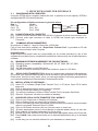
1) 1 - Phase, 2 - Wire mode (Select 4 wire connection mode)
2) 2 - Phase, 3 - Wire mode (Select 3 wire connection mode)
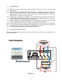
3) 3 - Phase, 4 - Wire mode (Select 4 wire connection mode) See Figure 1 for this
mode.
4.3.1 1- PHASE 2- WIRE SYSTEM (Select 4 wire connection mode ) :
[1.]
[2.]
[3.]
Used for Measurement of 1-phase power.
Can be wired on any input channel, most commonly used for single phase AC load
applications.
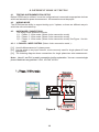
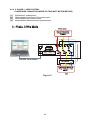
The following diagram shows connections for single phase two wire measurement.
Note:- Here V1 and Ph1 is used in connection just for explanation. You can connect single
phase Machine in any pair like V1-Ph1, V2-Ph2, V3-Ph3.
1 - Phase, 2 Wire mode
1Phase source
Max applicable
Voltage N:Phase
N
RS-232 Connection
R
Circuit breaker
Max applicable
Current per Phase
Figure 4
18
Load