1
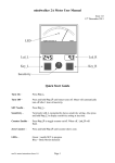
30th Sept 2009
mindwalker 3 (mw3) User Manual – V 2.0.4
Installation
First Time Install
Download the full install zip file. Unzip the file and run setup.exe, then follow on screen
installation instructions. If you have an install CD just run setup.exe.
The program will now run in Demo mode. If you have mw3 hardware then it is necessary
to install the USB drivers (see below).
USB Driver Installation
Unzip the downloaded USB driver file to a known location or insert the install CD.
1. Plug the mw3 hardware (black box) into a USB port on your computer. This will
launch the Windows Found New Hardware Wizard.
2. Select the ‘No, not this time’ option and continue.
3. Select ‘Search for the best driver in these locations’ and browse to the MW3_USB
folder. Click ‘Next’ to continue.
4. If a warning box appears saying that the software has not passed Windows Logo
testing, click ‘Continue Anyway’.
5. Windows should then display a message indicating that the installation was
successful. Click ‘Finish’.
6. The computer will now indicate that it has found new hardware again (USB Serial
Port) and present the Found New Hardware Wizard once more. Repeat steps 2 to 5.
Connecting to Hardware
Upon first running the program it will usually default to Demo mode. Select
Source>Connect to initiate a search for any connected hardware. It is sometimes
necessary to select Retry when prompted if the search fails to locate your hardware first
time. Upon exiting the program, it will remember the location of hardware for next time
and automatically search there first.
See the troubleshooting guide at the end of this document if problems are encountered
trying to connect to the mw3 hardware.
Settings
Under the Settings menu there are various options for the screen view and alerts.
The default settings invoked when the program is first run are stored in a file called
mw3.ini. After making any changes go to File>Save Settings As and save your changes
to a file of a different name. This ensures that future program upgrades will not overwrite
your customized setting choices. You can save as many different settings files as you
like. Simply use File>Load Settings to invoke any of them.
Dial Display
Two needles can be displayed on the dial.
One is equivalent to the needle seen on traditional analog meters and is influenced by the
sensitivity control.
The other (baseline) shows the Baseline Position according to the scale around the
periphery of the dial. This information is also displayed in digital form at the top left of
the dial panel.
Each needle can be set to a different width or be made invisible by selecting Settings >
Needle Widths >
Sensitivity Control
The sensitivity can be changed by:
1. Dragging the knob at the bottom left with the mouse
2. Clicking on the Up or Down buttons at the bottom right
3. Using the keyboard Up and Down cursor keys
Body Motion Detect
It is possible to detect needle responses caused by hand or finger motion on the electrode.
When this feature is enabled, such motion causes the needle to freeze and change colour.
Once body motion has ceased, there is a short delay before the needle returns to its
normal colour and unfreezes.
Body Motion Detect is enabled by checking the B-M Detect tick box at the bottom of the
dial panel. Note that even though the needle freezes, the scrolling graph does not, and
will show the body motion.
The sensitivity of the Body Motion Detect can be changed in Settings > Alerts > Body
Motion.
Baseline Drop Counter
This counter is disabled and set to zero when the program is opened. It is enabled by
clicking on the BD Count digital display. Note that it is only enabled when B-M Detect
is operating, and that it ignores any body motion. Use the Zero button to reset the count.
Scrolling Graph
This feature is useful for highlighting certain needle responses. It can be turned on of off
using the Show Scrolling Graph tick box.
Recording and Playback
This powerful tool records voice input from a microphone along with the needle actions
occurring at the same time. It requires that the appropriate settings (such as playback and
recording volume) have been configured for the audio card in your computer. This area
can be confusing and sometimes requires some experimentation to get familiar with it.
Recordings are made by clicking the record button (the one with the dot in the middle)
and can be immediately played back. No recordings are saved unless you explicitly do so
with the Save As button, and will be overwritten with the next recording. Use the Load
button to play back previously saved recordings.
A useful feature for demonstrations is the repeat facility. Check the Repeat box before
playback to run a continuous loop of the recording.
For playback of long recordings use the slider control to skip through the recording.
Best quality is obtained with a USB microphone system. Contact me for
recommendations.
Wireless Electrode
To switch between wired and wireless electrode systems go to Source > Sensor > Local/
Remote (Local = Wired, Remote = Wireless)
See separate documentation on use of the wireless electrode option.
Computer Performance
Electrode readings are sent to the computer at a rate of 50 per second. If all of these are
displayed on the screen then the needle motion will appear smooth. However, if the
computer can’t keep up the software will discard readings, rather like tossing items off
the conveyor belt on an assembly line in order to keep up. Any time readings are
discarded, a red stripe flashes at the left hand side of the dial panel. You can easily force
this situation by clicking on a menu item or dragging the application window.
In practice a jerky needle due to inadequate ‘real time’ response as detailed above is very
rare, especially on modern computers. Most importantly, it is not a problem provided one
is alerted to it. On slower computers it is recommended to not run any other applications
at the same time, and turning off the scrolling graph significantly reduces the demand on
performance.
The threshold of this alert can be set on the Settings > Alerts > Needle Lag menu item.
Start at the top setting and increase acceptable lag time if the red stripe flashes frequently
(can be quite irritating!). If the red stripe flashes frequently in normal operation on the
bottom two settings this would indicate a severe problem with performance or computer
task overload, and should be investigated.
Troubleshooting
There are two LEDs on the mw3 box, one green and one red, which aid diagnosis of any
problems.
In normal operation the green LED will flash. This shows that the unit is powered from
the USB cable.
When using the wireless electrode option, the red LED will also flash whenever there is a
break in the wireless link (also the word LINK will flash up in red on the screen).
A permanent red LED (with no green LED) signifies a fault condition – contact the
manufacturer.
1.
2.
3.
4.
No flashing green LED - check cable and connectors
Green LED flashing but “Hardware not detected” error message – see
below
Needle not responding – reassert (uncheck then check) Local/Remote
mode in Source > Sensor > Local/Remote
Still no needle motion – Check electrode wiring or switch positions on
wireless electrode
The “Hardware not detected” message means that Windows has failed to find the mw3
hardware on its USB ports. Usually simply unplugging the mw3 and plugging in again
after waiting a few seconds will rectify the problem.
If further investigation is required then proceed as follows.
Go to Windows XP Settings>Control Panel>System and select the Hardware tab.
Then select the Device Manager tab and you will be presented with a list of hardware
devices.
Expand the ‘Ports (COM & LPT)’ by clicking on the + sign to its left.
The mw3 should be listed here, for example ‘mindwalker (COM3)’ indicating that it has
been assigned COM Port 3. This information is useful in the event that you need to
contact the manufacturer.
Known Problems
A problem can arise with Windows XP due to the fact that the Plug ‘n’ Play feature can
think it has detected a serial port pointing device (Serial Ballpoint) and load that driver
instead. This results in the cursor uncontrollably flitting about the screen when the MW3
is first plugged in.
The remedy is to disable the mistaken device driver. Unplug the MW3 to regain control
of the cursor. From the Start menu go to Settings>Control Panel>System, select
Hardware tab and then the Device Manager tab. Click on the + sign to the left of ‘Mice
and other pointing devices’. If ‘Serial Ballpoint’ appears in the list, right click it and
select Properties, then check the ‘Disable in this hardware profile’ box. After this the
MW3 USB driver should install correctly. It is highly likely that this problem has been
fixed in firmware version 1.6 and above ( see Help menu for details of your firmware
version). Contact the manufacturer for details on upgrading firmware.
There have been a few occasions, particularly on laptops, when the mw3 has been
assigned a COM port already used by another device, for example an in-built modem.
The Device Manager shows that the mw3 is present (it is listed under Ports) but the
application software does not detect it. The COM port number should be increased by
going to the Device Manager, right click on mindwalker and select Properties, then Port
Settings, then Advanced. A drop down list of COM Port numbers is then available, and a
different one can be selected.
Should you wish to uninstall the mindwalker USB driver at any time, this can be done
with the Control Panel Add or Remove programs facility. The driver will be listed under
the following name:
FTDI USB-to-Serial Converter Drivers
Contacting the manufacturer
With the amount of junk email being sent, it is easy to filter out genuine messages by
mistake. To ensure your emails get through, make sure that “mw3” is somewhere in the
subject field, and email “meters” @ the web address.