1
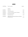
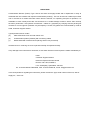
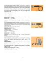
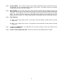
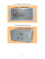
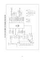
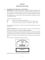
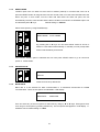
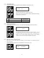
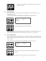
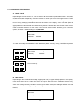
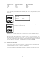
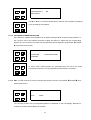
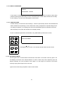
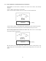
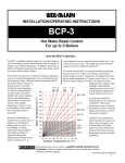
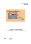
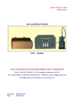
INSTRUCTION MANUAL CONTAMINATION MONITOR (FRISKER) TYPE: CM712 NUCLEONIX SYSTEMS PRIVATE LIMITED Plot No: 162 A & B, Phase II, I.D.A. Cherlapally, Hyderabad - 500 051. Ph : 91-040-27263701, Fax : 27262146, e-mail : [email protected] File Name : CM712_Man Date : 28-03-2012 CONTENTS CHAPTER No. Title of the contents Page No. Unpacking CHAPTER I Introduction 01-01 CHAPTER II Technical Specifications 02-07 CHAPTER III Front panel and Side panel controls / indications 08-10 CHAPTER IV Block diagram Description 11-13 CHAPTER V Operating Instructions 14-24 CHAPTER VI Availing services for Equipment Maintenance/ calibration and warranty clause 25-28 UNPACKING Contamination Monitor (Frisker) Type: CM712 has been thoroughly tested and is dispatched in ready to assemble and use condition with required contamination probe(s). This can be used as a table top mounted unit or mounted on a mobile stand with castor wheels. However, on unpacking and prior to operation, it is advisable to check visually and make sure that there is no visible damage caused in transit. Also checkup the items (instrument / sub-systems/ accessories / cables etc.) physically by verifying with the packing list contents for correct types & quantities. Any discrepancy if found, may please be communicated by email to Head, Customer support division. Typical packed cartons contain (a) CM712 Electronic main unit with mains cord (b) Contamination probes (ordered) with connecting cables (c) Mobile stand with castors fixed for placing CM712 unit (if ordered) All these items on receiving are to be unpacked carefully & inspected visually. If any damage to the instrument is observed, do not switch ON the unit and report the matter immediately to: Head Customer Support Division Nucleonix Systems Private Limited Plot No: 162 A & B, PHASE II, I.D.A. Cherlapally, Hyderabad - 500 051. Ph : 91-040-27263701/30918055, FAX : 91-040-27262146, e-mail :[email protected] In all correspondence regarding the instrument, please mention the type, serial number of the unit, date of supply etc., of the unit. CHAPTER - I INTRODUCTION Contamination Monitor Type : CM 712 manufactured & supplied by Nucleonix systems essentially serves as a frisker and is primarily designed to measure Alpha, Beta & Gamma contamination, on work benches, clothing, hands etc., in Radiochemical plants, Nuclear Power plants and other similar installations. It is designed to be table top model or it can be mounted on a mobile stand with castors. It operates on AC mains 230V, 50 Hz. This unit has a wide choice of contamination probes for Alpha & Beta-gamma contamination measurement. FEATURES: Manufactured confirming to ANSI N 42.17, to performance specifications Complies to IS -9000 part III & V Interference test as per IEC61000. State of art electronics, uses microcontroller Compact, light weight & elegant Choice of Beta / Alpha contamination probes Counting accuracy +/-15% with contamination probes Alpha/Beta contamination in CPS / CPM with auto ranging Time Constants : LO, MED, HI Modes : CPS / CPM / Preset Scalar Built-in serial port & parallel port 1 CHAPTER – II TECHNICAL SPECIFICATIONS 2.1 Detector assembly : The instrument can be supplied with three detector probes, two detectors for Beta gamma and one for alpha, with the specifications given below. 2.2 Beta gamma detector : Side window probe with Halogen quenched GM detector, thin walled (25 / 30) mg/sq. cm. in a protective housing with a rotatable shutter for cutting off beta particles. This will be used for measuring beta as well as gamma contamination. End window probe consisting of an End window Halogen quenched GM detector 30 mm dia, 3-4 mg/cm^2 thickness mica window housed in a suitable protective cover with handle. The end-window is provided with a removable cover. • Detection Efficiency : Greater than 2-2.5% for side shutter type probe & Greater than 15% for End window type for Sr-90 Beta particles. • 2.3 Probe Construction : Hand-held type; viewing side is provided with a removable cover. Alpha Detector : ZnS (Ag) scintillator, approximately 20 mg /cm^2 on perspex; covered by 1 mg/cm^2 aluminised , pin-hole free, light-resistant mylar film, protected by a suitable thin metallic grill. The scintillator is optically coupled to a suitable photomultiplier tube along with an appropriate low noise pre-amplifier etc. • Detection Efficiency : Greater than 25% at centre and uniform within 5% for plutonium alphas over complete detector area. 2.4 • Probe Construction : Hand-held type; viewing side is provided with a removable cover • Sensitive Area. : 100 sq. cm. Electronic Unit : The electronic Unit shall comprise of Low voltage power supplies, EHT supply unit, count-rate meter based on Intel family/microcontroller, and an audio visual alarm system. The unit is provided with two UHF connectors, one for Alpha detector and other for Beta gamma detector along with the corresponding input circuit. At a time only one detector can be used. 2.5 Low Voltage power supply : The low voltage power supply unit will supply the DC power supplies required for the operation of the electronic module. It has very good line voltage and load regulation. It is fitted with Mains line filters to avoid line interferences. 2.6 EHT Supply : It provides EHT voltage for the working of the GM / scintillation detectors. Its output is continuously variable from +300V to +1500V. Output can be adjustable through front panel keypad and EHT should be displayed on the display. 2 2.7 Count-rate meter • Ranges : 0- 50, 0-500, 0-5000 and 0- 50,000 counts per minute . The range selection is automatic depending upon current countrate. • Time Constant : Varies inversely in the range of 1 sec to 10 sec. • Display : 16x2 LCD display is provided for display of countrate and for textual message indication The instrument also displays the reading in a calibrated LCD Bar graph display with the shape of an analog meter scale. • Audio indication : Chirping audio is provided to indicate the contamination of the object being monitored. The audio will be one chirp per pulse. • Overflow : > 50000 CPM • Over load : > 99999 CPM • Accuracy : +/ - 5% Full scale. • Calibration Accuracy : +/- 5% Over the full range. • Calibration Stability : Better than +/- 5% over a period of six months. • Testing Facilities : Provision to inject a suitable pulse generator signal for routine testing of Alpha / Beta Count rate sections is provided on the rear panel. Additionally a test pulse mode through software for checking count-rate meter is provided. 2.8 Instrument Fault indication : EHT failure: Visual alarm with flashing red LED indication & “Eht” message on LCD display Detector failure: Visual alarm with flashing red LED & “d-Fl” message on LCD display. Microprocessor / microcontroller failure : Visual alarm with flashing green lamp Fault indications are cleared automatically if normal status is resumed. 2.9 Audio Visual Alarm system • Alarm setting range : 0 to full scale of the range selected • Alarm setting accuracy & stability. : Better than + /- 10% over a period of six months . • Alarms are indicated by Red (LED) large area window display and loud audio alarm • Distinctive EHT/Detector failure alarm • Large Area instrument “ON“ indication. • Provision for display of alarm set point on demand through keypad • Alarm set-point is adjustable continuously by the front panel keypad / hand held configurator or from Remote PC with password protection. • Alarm annunciation scheme : The audio and visual alarm will go off automatically when the reading falls below the alarm set point. 2.10 Housing : All the electronic sub-systems are housed in a single enclosure. All the controls and display are on the front panel. The cabinet is Vapour-tight , rugged & elegant. 3 2.11 Remote /External Console • 4 - 20 mA full scale output. Output circuitry shall be able to drive 200 mtrs. of twisted pair of wires. • Two sets of potential free contacts of Alarm relay (Change over). Contact rating 3 Amps at 250 VAC. • 9 pin D connector for RS485 communication. • All these signals are terminated on a suitable connector (Allied Connectors). The corresponding unwired mating plug will be supplied with the monitor. 2.12 RS-485 Specification : Type : Isolated Multi-drop serial communication port, half duplex bi-directional communication Address : User configurable from 0 to 255 Protocol : MODBUS RTU Bit Rate : user 19200 Connector : 9 Pin D – Type Connector 2.13 Self Diagnostics : The monitor has built-in self diagnostics. On being powered it will perform tests to ensure that all components and sub systems are functioning properly . It will check for the Power supply, High Voltage Supply, Detector, Counting and measuring circuits, Alarm Systems and Display Systems. The firmware will not halt monitoring / data acquisition function any time. The firmware is designed for high reliability and availability. Test points are provided for checking the EHT voltage and jumpers are provided for connecting external input pulse signals. 2.14 Input Power : 230VAC +/-10%, 50Hz, single phase supply. Power ON/OFF indication is provided with Neon indicator. Spike suppressor and line filter are provided. 2.15 o Environment : The instrument shall be able to withstand temperature upto 50 C and relative humidity upto 90% in radiation areas. 2.16 Instrument Trolley : The instrument is provided with trolley as an accessory to house all the hardware like detector probes, Electronic unit etc. The Instrument trolley is made of M.S. with castor wheels. 2.17 Environmental EMI / RFI & performance Compliance: This instrument is designed to comply to IEC 60325 for its radiation performance, environmental & EMI / RFI compliance. For EMI / RFI compliance, test specifications specified by IEC 61000 standards are applicable. 4 ACCESSORIES Beta - Gamma Contamination Probe (a) G.M. Detector : (BCP1) (thin walled) Thin walled GM detector (Type : with GM 137) housed in S.S. envelope having handle and sliding window for Beta radiation discrimination. Cable length : One Meter Operating Voltage : 500V Cathode wall thickness : 40-60 mg/cm2 Probe dimension: 210L x 32D in mm Gamma sensitivity : 45 c/s / mR/hr. BCP-1 b) End window G.M. Detector Probe : (BCP2) Uses GM125 detector with 1" end window thickness 1.5 - 2 mg/cm2. End cap is to be removed for Beta Contamination measurement. For Gamma radiation measurement, end cap is to be retained. BCP-2 (c)Beta - Gamma Contamination Probe (BCP3) :This probe is offered as a part of Beta-Gamma Radiation Survey Meter type RM703E. ** This uses a thin walled GM tube which is housed in a cylindrical shell made of Aluminum. Detector side of the cable has a cable gland arrangement with cable length being 1.0 meters. There is a rotating shutter arrangement made of SS shell, which is kept open for Beta measurement. Detector : Thin wall Beta-Gamma detector GM133 or its equivalent. Detector Probe : 35cm L x 3.2cm Dia Operating Voltage : +900V Cable Length : 1.0 meter BCP-3 ** This also serves as a clothing probe, for Beta-Gamma hand, foot & clothing monitor or as a Contamination probe for bench model Contamination Monitor. (d) Alpha Contamination Probe type ACP2 of Nucleonix make serves as a Alpha Contamination Probe with a viewing area of approx. 20 sq.cm (2” dia). It is designed to work with Nucleonix make Contamination Monitor (Bench Model) CM712 or its equivalent. Alpha Scintillator Screen: Circular Scintillator ZnS screen covered with aluminized mylar foil of 25mm dia will be used. PMT : 2" PMT of Hamamatsu or ETL or Equivalent. Viewing area : 20 sq.cm Approx ACP-2 Operating Voltage Range : 800V to 900V Efficiency : Better than 25% Cable length : One meter (by default) Application: Recommended for use where viewing area of the order of 2” dia is adequate. 5 (e) Pan Cake Detector Probe type PCP-1, manufactured & supplied by NUCLEONIX SYSTEMS is an ideal choice for Contamination Monitor both with bench model & portable type of units. It has a wide circular viewing area of 1.75” dia window to allow Beta. Detector body is enclosed in a thin SS enclosure having a lid which is closed for gamma doserate measurements. This probe measures gamma doserates upto 500mR/hr & Beta contamination both CPS & CPM. Probe has a nice handle to hold made in black nylon. PCP-1 Detector Type : Pan Cake-1 Gamma Sensitivity : C/S/mR/hr (Co60) : 60 Dimensions (Detector) : Length : 3.0 Inches Effective Depth : 0.5 Inches Maximum Dia : 2.11 Inches Application: This is offered both for Beta / Gamma Contamination Monitors. (f) Pan Cake Detector Probe type PCP-2, manufactured & supplied by NUCLEONIX SYSTEMS is an ideal choice for Contamination Monitor both with bench model & portable type of units. Probe has a nice handle to hold made in black nylon. Detector Type : 2no.s of Pan Cake detectors. Probe size : 6.5 X 11.5 cm Active area : 75 sq.cm (approx) Gamma Sensitivity C/S/mR/hr (Co60) : 60 per detector Dimensions (Detector) : Length : 4.72 Inches Effective Depth : 0.90 Inches Maximum Dia : 1.96 Inches Application: This is offered both for Beta / Gamma Contamination Monitors. (g) Alpha Contamination Probe : (ACP1) Alpha Contamination Probe type ACP1 of Nucleonix make serves as a large area (Approx. 100 sq.cm) alpha contamination probe. It is designed to work with Nucleonix make contamination monitor CM712 or its equivalent. Alpha Scintillator : ZnS (Ag) Scintillation film covered with aluminized myler foil for light tightness is used as the detector PMT : 2" PMT of EMI make 9266B Viewing area : 100 sq.cm Approx (A ZnS Scintillator screen of 10x100mm will be used) with a conical light guide for 2" PMT. Operating Volage Range : 950V to 1050V Efficiency : Better than 25% Cable length : One Meter (by default) 6 PCP-2 ACP-1 (h) Mobile Stand (MS-1): Mobile stand with a base plate fitted with lockable caster wheels & an SS cylindrical column to support the top base plate & the instrument has been designed & made available as an accessory to the bench model contamination monitor. Top base plate onto which instrument is mounted can be tilted slightly so that viewing angular face of the instrument is convenient to the user. This top base plate can accommodate contamination probe also. Mains supply board with required sockets and switches are provided on the trolley. Mobile Stand Material: Fabricated in SS Base Plate Size: 52 cm Length x 43cm Depth SS column a) Height : 101 cm b) Diameter : 16 cm Top plate size : 43.5 L x 29 D cm Adjustable Angle: 20o 7 CHAPTER - III FRONT & REAR PANEL CONTROLS & INDICATIONS 3.1 FRONT PANEL CONTROLS AND INDICATIONS 3.1.1 CUSTOM LCD ANALOG DISPLAY: This is a visual LCD display specially designed by Nucleonix systems, to have FOUR digit, Digital value indication of the parameter under measurement with decimal indication option. Additionally there is analog scale (bar graph) indication which is lit proportional to the digital value. This also shows-up other parameters such as measurement ‘unit’ selected, EHT failure indication. Additionally there are two symbolic / mimic icons for audio ON (buzzer) condition & Head phone ON condition. 3.1.2 NORMAL LED LAMP: This glows when the count rate has not exceeded preset level after last reset 3.1.3 MAINS ON-LED INDICATION : This LED glows when the AC mains power is switch ON to the unit 3.1.4 ACTIVE LED DISPLAY : This a large size RED LED indication gets, lit, when the countrate exceeds preset level. 3.1.5 NORMAL LED INDICATOR : This is a green LED indicator, glows ON always in the normal condition. That is when the countrate is below the preset value, set for alarm condition. 3.1.6 INTELLIGENT KEYPAD: (a) PROG key button : This key is an important one which facilities the user to program the operation of the instrument for different modes / conditions. There are two ‘PROG’ keys i.e., left & right arrow keys. These are useful to navigate while going through various program functions, forward & backward. More details are covered under "CHAPTER IV OPERATING INSTRUCTIONS". START key button : This is used for starting of acquisition and printing, once all the program parameters have been set. STOP key button : This key can be used to terminate acquisition and printing in between. In the normal course acquisition will stop automatically at the end of preset time and the data printing will stop once the end serial number setting for printing has reached. INC/DEC key button : These keys are used while setting the programme parameters to increment and decrement a value or to change the option selected to another value available. STORE key button : This key is used for storing the readings or data values in the following way, in the manual mode of storing only. (b) c) (d) (e) At the end of acquisition for a preset time if user presses this button, data counts will be stored and the Sl.No. in the display increments to the next value. In CPS/CPM modes the current CPS/CPM is saved on pressing this button. 3.1.2 LCD DOTMATRIX DISPLAY : This is a 20 X 2 alpha numeric LCD dotmatrix and responds to all the commands from the keypad and displays programme parameters, current HV, data counts, preset and elapsed times etc,. 3.2. REAR PANEL CONTROLS AND INDICATIONS 3.2.1 MAINS ON / OFF TOGGLE SWITCH : This is a DPDT toggle switch, switches ON, 230V, A.C mains power to the unit HV Preset : This is a trimport adjustment, to set the HV value to the desired biasing value. HV socket : This is an MHV socket on to which HV output is brought out, service as a test point HV ON/OFF toggle switch : This is a DPDT toggle switch to power up HV circuit for its functionality. 3.2.2 MAINS SOCKET : This is a 3 pin mains socket for connecting the power cord. 3.2.3 FUSE HOLDER : This is a fuse protection provided in the mains supply (1.5A). 8 3.2.4 ALPHA PROBE : This is a MHF socket to which Alpha contamination probe of Nucleonix make or its equivalent can be connected through a MHV to UHF cable. The system will work as an Alpha Contamination monitor under this condition. 3.2.5 BETA PROBE : This is a MHF socket onto which this Beta contamination probe Beta-gamma probe side (either shutter type or End window hammer type of probe or pancake detector probe) gets connected. On the detector side of the contamination probe, RG59 cable is fixed into the cable gland. The other end of this cable which has MHF male connector is connected onto the unit. System permits connection to a variety of Beta gamma contamination probes as indicated in figures. 3.2.6 TEST INPUT(S) : (A) Alpha : This is BNC input to inject –ve tail pulse to test functionality of alpha channel counting electronics. (B) Beta : This is BNC input to inject –ve tail pulse to test functionality of beta channel counting electronics. 3.2.7 17 PIN I/O CONNECTOR : This MS-series I/O connector provides current loop output & relay contact for external use. 3.2.8 9 PIN D-TYPE CONNECTOR PAIR : This pair of connectors carry RS485 IN-OUT signals 9 FIG. CONTAMINATION MONITOR FRONT VIEW FIG. CONTAMINATION MONITOR REAR VIEW 10 CHAPTER – IV BLOCK DIAGRAM DESCRIPTION 4.1 The following paragraphs are to be read by referring to the block diagram Fig. on next page Block diagram illustrates complete system realization, including one G.M detector probe & a second Alpha contamination probe. Of course at a time one probe only is to be activated. This contamination monitor (Frisker) CM712, is an integral, mains operated, model. It can be table top mounted or mobile stand mounted. It is basically designed for Frisking of personnel in Radiochemical plants or waste immobilization plants, or similar other facilities. 4.2 SMPS : It draws 230V, A.C 50 Hz and generates +12V @ 0.5, +24V @1A & 5V@ 4A 4.3 HV module generates (0-1500V @ 1.0A) : This current essentially takes input power from +12V & +24V & generates 1500V @ 1mA. This circuit is primarily a DC to DC converter. Primary DC power is switch at RF frequency through MOSFET differential drivers. Secondary of the RF transformer steps-up the AC voltage by 60 times, it is converted to DC through a voltage doubler circuit. Through feedback loop & regular chip, regulation is achieved. Depending upon the detector connected one can set the HV bias to the desired voltage. Typically for a G.M detector contamination probe it may be +500V or +900V and for Alpha contamination probe it is +900V. 4.4 Alpha & Beta contamination probes : These are essentially an (a) Alpha contamination probe of 100 Sq. cm area. Zns scintillator coupled to PMT serves as the alpha detector. PMT, HV biasing circuit & suitable anode load resistor & coupling capacitors give –ve tail pulses for the alphas detected. This goes to –ve tail to TTL converter. (b) Beta gamma contamination probe, which essentially is a thin walled long GM detector, covered with an SS sliding shutter type of enclosure. Detector output (-ve tail pulses) go to tail to TTL converter from here. 4.5 Tail pulse to TTL converter : These are two separate hybrid pre-amplifiers with built-in font end charge sensitive stage & amplifier. Followed by this there is a comparator & a monostable. One is in Alpha detector probe path & the other in the Beta probe path. 4.6 AMUX : This is addressed by microcontroller port control to select either Beta or Alpha detector output to the counter. 4.7 2 6 digit counter : AMUX output goes to counter, which is connected to I C bus through which this counter reads the counts value into microcontroller & displays on to custom LCD display & also proportionate value on analog bar scale. 11 4.8 12 bit DAC : This is programmed through microcontroller to set any desired DAC value. The output of DAC sets desired HV in the HV module. 4.9 4 CH-ADC : This reads fraction of +24V, +12V & HV, into microcontroller & reports any failure of LV or HV supplies once they fall below a preset value. 4.10 2 EEPROM : There is another memory chip that is interfaced to microcontroller through I C bus. This stores all program parameters & data values. 4.11 +5V (ISO) & GND (ISO) : This isolated +5V & GND are generated by a DC-DC converter chip, which take +5V of SMPS as the input source. This opto isolated supplies are used by opto-isolator chip RS485 converter receives opto isolated transmit & receive signals. This chip give data (+) & Data (-) output for data communication into PC 4.12 Microcontroller & other associated peripheral chips : Keypad is interfaced through I/O expander to microcontroller. 4.13 Custom LCD display & 16x2 LCD display : Both these are interfaced to microcontroller through 2 I C bus. 16x2 LCD display facilitates selection of program parameters and loading of their values. User can program & set the values through keypad interface. Custom LCD displays digit value of the countrate / Bq it also show-up proportional value on the analog bar scale. Additionally fault diagnostic / failure indication is also shown on this custom LCD. Details are explained under ‘Operating instructions’. 4.14 Audio – visual alarm status indicators: These are ‘NORMAL’, ‘ACTIVE’ & Buzzer are interface through microcontroller control ports & drivers. Under program control alarm annunciation takes place as per the set conditions. 4.15 DAC-Current loop output circuit : A programmable serial DAC, interfaced to microcontroller provides analog signal output proportional to the digital value of the selected range. This output is converted to current output (4-20mA) by a single chip. 4.16 ACK & RESET commands : These keys are directly connected to the microcontroller. 12 13 FIG. BLOCK DIAGRAM OF CONTAMINATION MONITOR CHAPTER -V OPERATING INSTRUCTIONS 5.1 CONFIGURATION AND OPERATION OF THE INSTRUMENT INTRODUCTION: This chapter illustrates details on configuring and operating the instrument, for a desired installation in a plant environment. Basically, operating instructions are illustrated with the help of menu options / responses that appear on 16x2 LCD / Analog LCD displays. Each of the menus facilitate the user to choose function/ value to be set or entered as desired for its operation, at the installed location. Front panel keypad is used for programming the contamination monitor for its functionality & operation. An important note (to follow) for the user is / - - key can be used to increase the value at the cursor position / toggle the option. - key can be used to shift the cursor position from right to left / toggle the option. “PROG” key can be used to enter in to the menu. Once all necessary interconnections are made as per the system interconnection table, the unit may be switched ON. POWER ON CONDITION: When instrument is switched on, initially, the audio visual observations noticed till the indications shown are stable is called power on condition. When the power is switched on, the following audio visual indications are noticed. First, to start with, one audio beep is heard. Followed by this the following visual indications will be lit. Red cluster LED window will glow for a while and goes off. Followed by this, normal cluster LED window will be lit. The status of LCD and large custom LCD display with power on condition is given in the following table. As soon as the unit is switched ON the below screen appears, CONTAMINATION MONITOR By default unit goes into acquisition mode and displays the following. 14 BETA XXXXXXCPS A Blinking Now a blinking character ‘A’ appears indicating that unit is in acquisition mode and is calculating countrate. The countrate in Alpha /Beta channels are refreshed on the large LCD segment display every 4 seconds. Average countrate of last 4 measurements is written to LCD 7-segment displays. Now the unit can be configured through a detachable keypad. Now on pressing ‘PROG’ key the display shows as below ^ ENTER PASSWORD: XXXX Now using or keys enter password to get authorization to change program settings. Alternatively enter factory default password. 5.1.1 PRESET ALARM LEVEL Contamination Monitor will show the current default alarm set value of 50 CPM. If user wants he can change to another value, by or keys. Use PROG key to select below screen, PRESET ALARM LEVEL ^ XXXXX Now using & buttons set the preset level for alarms activation. On pressing , digit at location of the cursor is incremented by one unit rollover. 15 5.1.2 RESET MODE ‘RESET’ option user can either set it as AUTO or MANU (manual). In manual reset, user has to press the RESET button to bring back the unit into normal mode, once the dose rate falls below the alarm set point. In auto mode, once the dose rate falls below the alarm set point, the unit automatically returns to normal mode and the alarm condition is turned off. AUTO/MANU option can be selected by or keys. Default setting is = Manual Select below option by using PROG keys RESET MODE AUTO / MANU By pressing or keys we can select Reset mode as AUTO or MANU to reset alarms automatically or manually on user prompt after alarm levels fall below preset levels. Once RESET MODE, option is selected user can now press ‘PROG’ button to go to next menu option i.e. ‘Audio Status’ 5.1.3 AUDIO STATUS AUDIO ON STATUS Audio STATUS is by default ON 5.1.4 BAUD RATE Baud rate is to be selected for data communication in a networked environment for RS485 communication. There are two options as indicated in LCD display BAUD RATE 9600/19200 One can select any of the two options for baud rate by using by or keys. Having done that, user can go to next option by pressing ‘PROG’ key. The next option that appears in LCD display is hardware check. Default setting is = 9600 16 5.1.5 HARDWARE CHECK To perform hardware check, using PROG or PROG keys select below screen, HW. CHK? OK Now press or buttons to perform self- check. Based on the various possible failure conditions appropriate messages are displayed as shown below. No. 1. 2. 3. 5.1.6 Conditions Message on 7 segment Display EHT LS_FL d_FL HV is faulty +12V or +24V is faulty Zero counts for more than 10 min DETECTOR EFFICIENCY To view and the set Detector Efficiency, using PROG & PROG keys select below screen. DETECTOR EFF. XX.X % Now press & buttons to adjust the detector efficiency. This is required to display the measured value in terms of activity (Bq). By default it is set to 00.0% default. Having set this & upon pressing 5.1.7 ‘PROG’ key, the next menu option that appears is SET UNIT. SET UNIT (setting of engineering unit) Here there are Three Units options that appear in the LCD display. The measuring units are CPS,CPM and Bq. To view and modify the SET UNIT, using PROG keys select below screen, SET UNIT CPS/CPM/Bq 17 Now using 5.1.8 or buttons, modify the SET UNIT to either CPS or CPM or Bq as needed. DEVICE ADDRESS This is a three character numerical value. This is RS485 address of the instrument limits 0 – 255 Default settings is = 000 To view and modify the DEVICE ADDRESS, using PROG keys select below screen, DEVICE XXX ADDRESS Use or keys to select the device/unit no. Default address is 000. (This is used when multiple units are networked) User can select desired three digit address (ID) of the instrument. Use or keys to load this value. Having completed this task press ‘PROG’ button for the next menu i.e., ‘AUTO ACK’. 5.1.9 AUTO ACKNOWLEDGE By or one can select or toggle this option. If it is selected as ON, after 5 minutes automatically alarm is acknowledged & audio alarm goes ‘MUTE’. However visual alarm remains active. Default setting is = OFF. To view and modify the AUTO ACK status, using PROG keys select below screen, AUTO ACK OFF/ON (5 min) Use or keys to select the required mode. When AUTO ACK mode is ON, then the audio will get muted within 5 min of generation of alarm condition The next menu option is ‘MAX SCALE’ which is prompted on pressing ‘PROG’ button. 18 5.1.10 CURRENT LOOP MAPPING A. MAX. SCALE Depending on the unit chosen i.e., CPS or CPM or Bq, the maximum permissible scales are 2,000, 50,000 and 50,000 respectively. User can choose any value upto a max of this upper limit & a value above the minimum value. Any value chosen out of these boundaries will be ignored, (at the time of saving settings) and default values will be loaded. In the display, chosen unit will appear & appropriate max value desired can be entered by the user. Similar is the case for other units such as CPS or Bq. After selection of max. scale, user can now select ‘PROG’ button to go to next menu option, as follows. Default setting is = 10,000CPM. MAX CPM (4-20mA) XXXXX To view and modify the CURRENT LOOP MAPPING (MAX. SCALE), using PROG keys select below screen, MAX. CPM ^ (4-20mA) XXXXX Use & keys to enter the MAX. count rate/ activity which corresponds to 20mA current o/p. B. MIN. SCALE Depending on the scale selected initially, appropriate unit (i.e typical CPM) appears in the display. User cannot enter the min. scale value which is equal or above the max. scale value selected. Any value not meeting boundary conditions will be ignored while saving the settings & default value will be loaded. Similar if the engineering unit changed then the min. & max. scales are tabulated as follows, MIN CPM (4-20mA) XXXXX 19 Engineering Unit Max. scale (4-20mA) Min. scale (4-20mA) CPS 2000 0000 CPM 50000 00000 Bq 50000 00000 To view and modify the CURRENT LOOP MAPPING (MIN. SCALE), using PROG keys select below screen, MIN. CPM (4-20mA) ^ XXXXX Use & keys to enter the MIN. count rate/ activity which corresponds to 4mA current o/p. Followed by this, on pressing ‘PROG’ button, the following menu appears ‘load default settings? Note : Max. & Min. scales are primarily for current loop scaling, for control room operation. Also, in the visual LED display also the same scales are set. Any value exceeding this max. scale will show as over range, as per definition in the LED display However in the lower LCD display it continues to show dose rate, as per actual value. Default setting for Min Scale is = 00000CPM. 5.1.11 LOAD DEFAULT SETTINGS? In case the user wants to retain default settings, he can skip all the previous menus & select this menu & chose option by pressing or key for default settings. To load FACTORY DEFAULT SETTINGS, using PROG & PROG Keys select below screen, 20 LOAD DEFAULT OK SETTINGS? Use or key to load the default factory settings. OK message is displayed once the settings are updated 5.1.12 COUNTING CHANNEL SELECTION Each Electronic module can be operated as an Alpha counting module or Beta counting module. For this, the EHT has to be adjusted as 500V for Beta and 900V for Alpha and the corresponding detector is to be connected. To select the corresponding channel adjusted, using PROG & PROG keys select below screen. COUNTING ALPHA/BETA/TEST CHANNEL Use or keys, select the desired channel as ALPHA, BETA or TEST mode. In TEST mode, internal pulses are generated which are fed to the pulse processing electronics. This is independent of the Detector connected. 5.1.13 EHT: To view the EHT set for the corresponding detector channel, using PROG & PROG keys select below screen. EHT: XXXX The currently set EHT to the corresponding detector is displayed on the LCD display. Normally for ALPHA we set 900v and for BETA we set 500v. 21 5.1.14 MODIFY PASSWORD MODIFY PASSWORD YES/NO If user wants to change the pass word, he can do so by or key. Select no option to retain same password. Having done that, finally we have completed all the ‘PROG’ button functions & are ready to save settings. The next menu that appear as given below. 5.1.15 SAVE SETTINGS Use or keys to save all the above settings. These are permanently stored in the EEPROM and will be recalled at next powering on of the instrument. Having configured for required settings unit is now ready for operation, once settings are saved unit automatically gets into operation mode and starts acquiring Count rates and indicates in the display visually. To save confabulated parameters in EEPROM, using PROG keys select below screen, SAVE SETTINGS? Now press or buttons to store the data into EEPROM. After data is stored OK appears on the screen. This indicates that the data has been stored 5.1.16 ACQUISTION MODE The unit goes back to COUNT-RATE measurement mode within 15 seconds of last key press. The unit displays count-rate of the selected detector in CPS or CPM or Bq mode, depending upon the detector selected. The Time constant for the system is in the range of 2 seconds to 8 seconds inversely varying with respect to the count-rate. Typical screen shot during acquisition mode is shown below 22 5.1.17 FAULT DIAGNOSTIC, FAILURE INDICATION, IN THE DISPLAY (A) EHT failure : This EHT failure is indicated in the custom LCD as follows, under following conditions. (i) EHT – ON/OFF switch is kept or in OFF position (ii) EHT output has failed completely & there is no output or it is below specified value. ALPHA XXXXXXCPS A Blinking In this EHT failure condition, in analog display EHT is appeared along with unit previously selected In display, lastly selected channel along with unit selected displayed showing zero counts (B) Low voltage supplies failure condition (For +24V & +12V) : When +24V or +12V fail, display shows failure condition as given below. ALPHA XXXXXXCPS A Blinking Both EHT failure & low voltage supply failure condition are sensed by recoding fraction of the voltage through ADC into microcontroller to indicate the above display status in the custom LCD display. 23 (C) Detector failure condition (D-FL) : When the detector signal is not received for about 10 minutes this condition arises & the custom LCD will show up as given below. ALPHA XXXXXXCPS A Blinking When the Contamination Monitor (CM712) unit is in operation with any of the detector probes, it is pressured that atleast once in 10 minutes there will one radiation event that gets detected & counts. If there is no event received within 10 minutes, then the microcontroller senses this failure to show up the above d-FL display indication. This also happens if no detector probe is connected & operating voltage to the detector is not set to the desired value. 24 CHAPTER – VI AVAILING OF EQUIPMENT MAINTENANCE/ CALIBRATION SERVICES AND WARRANTY CLAUSE 6.1 GENERAL As per the warranty clause of the company, we provide one year warranty during which period we provide free service at our works. Hence in case of any mal-function in our instruments, you are requested to send the unit back to our works by RPP/COURIER/SPEED POST PARCEL/GATI/XPS/door delivery. We shall arrange immediate rectification/replacement within two weeks from the date of receipt of the equipment at our place. Please note that the equipment will be serviced at our works only. The equipment is to be sent to: The Servicing Department NUCLEONIX SYSTEMS PRIVATE LIMITED Plot No: 162 A & B, PHASE II, I.D.A. Cherlapally, Hyderabad - 500 051Ph: 040-27263701/329145448/32918055 E-mail: [email protected] www.nucleonix.com For all the Radiation monitoring equipment, detectors built-in or external probes will not have oneyear warranty, but only inspection warranty at the time of supply is provided. Since detectors will / may have fragile glass construction, we do not provide warranty. In case of failure of these components, Nucleonix will supply detector replacement at cost-cost price. Note: In respect of all types of portable radiation monitors, it may be necessary to checkup and recalibrate the equipment once a year at our works. 6.2 EQUIPMENT REPAIRS / SERVICING POLICY (WITH IN INDIA) (a) During Warrantee The following procedure is to be followed by the customers with in India for availing services/ repairing facility during warrantee period. Equipments are to be sent to our works for availing free repair services during warrantee, after the customer receives approval from the customer support division, by sending an e-mail. For all equipments, costing less than 6.0 lakhs one year warrantee & free service is offered, when the equipments are sent to our works only. For larger systems such as installed systems, networked systems, specialized systems, costing more than 6.0 lakhs during one year warrantee, free service is offered at site. Field service Engineer will be deputed subject to warrantee terms & conditions. This does not include personal computer related problems, for which local computer service provider of the PC vendor is to be contacted. Also for software related problems online support will be provided. Software support doesn't include cleaning of virus problems etc. When the equipments are sent to our works for warrantee services, they are to be properly packed with adequate cushion to prevent any transportation damages. Nucleonix Systems is not responsible for damages or loss during transportation. Packing / Freight charge is to be borne by customer when he sends the equipment to our works. However when we return after servicing packing will be Nucleonix responsibility & Freight charges will be to your account. Only services are free. Please indicate in your correspondence equipment model & serial number. All the equipments are to be sent to our works only on door delivery basis. For Door Delivery Transportation contact XPS/GATI cargo in your city / town or a reliable courier service to pick the consignment from your place. For their nearest local address & phone no's look into their websites. Transit insurance if the customer feels is necessary it is to be covered. Nucleonix Systems will not receive the equipments sent by other modes of transportation, such as Rail/Road. After servicing, equipments will be sent back by same mode of transport such as XPS/GATI/COURIER/RPP. 25 All types of Radiation detectors, glass ware, PMTs etc which are fragile are not covered in warrantee, if the failure is due to physical damage, external or internal due to shock, dropping, miss-handling etc. If the failure is due to a natural fault then only it is covered under warrantee for a limited period of three months. However complete electronics is covered for 1 year warrantee. You can also send the equipment personally to our works for repairs either during or after warrantee, after fixing up with our service dept (Customer Support Division). If possible we may repair on same day or your person can stay for a day or two & get it repaired & or calibrated. (b) After warrantee Services On expiry of 1yr warrantee if you like to send the equipment (low cost less than 6.0 lakhs) for repairs to our works, you may please observe the following procedure. Send an e-mail with details mentioning that you agree to pay service charges which includes: Basic service charges per unit / module in the range of Rs: 2500 to Rs : 10,000 depending on the sophistication of the unit calibration charges ( if applicable for your equipment) + cost of components + packing charges + Return Freight charges @ actual. Once our customer support department responds & requests you to despatch the equipment to our works for repairs, you may do so by following the steps given below. Followed by this you can send the equipment straight away if it is within 5 yrs old. If the equipment is beyond 5 yrs old, then also you can send it for repairs, however only after you receive confirmation from Customer Support Division, that it is repairable & is not an obsolete model. If the design is obsolete then customer support division (CSD) may give you 'buy back' offer to replace with new model or upgrade it with electronic circuit boards & enclosure. For all installed equipments costing above Rs: 6.0 lakhs which are larger in size & for which field servicing only is recommended, you can obtain a quotation with relevant details by sending an e-mail & avail the services accordingly. For all field servicing jobs, since we need to depute engineers, it is likely, to take time & also it will cost more which includes Engineer's TA & DA etc., apart from basic service charges + cost of spares etc. Please note that basic service charges will be different for different products depending upon sophistication. Also in some cases it may not be possible to fix-up the problems in the field itself, in such cases we may advise you to send them to our works. For all jobs to be serviced in the field, customer is requested to provide adequate details on the nature of problems, to enable our engineer to come prepared with adequate spares. For any additional information send an e-mail to [email protected], Atten: Customer support division. 6.3 EQUIPMENT REPAIRS / SERVICING POLICY (FOR EXPORTS) Equipments, manufactured & exported are subjected to a well defined quality assurance (QA) plan & Factory acceptance tests (FAT). Nucleonix systems has the following policy to provide maintenance support to overseas customers either directly or through international dealers / distributors. (a) During & after warranty: For minor problems, which can be handled by customers, servicing tips have been provided in the user manual / servicing manual. Also most of the equipments have built-in fault diagnostic features which will indicate to the user nature of problem in the equipment. Based on the visual indication in the instrument Display, user can take corrective action or contact Nucleonix systems by email for help. Nucleonix systems will guide in localizing the defective part / module or sub-system by interacting with the customer if required. Skype will be used for communication. During warranty free replacement of sub-system or board (PCB) will be done. However customer has to send defective sub-system back to Nucleonix system with-in 15 days on arranging replacement. During & after warranty, any Freight charges & customs clearance charges are to be borne by customers, both ways. If it is a manufacturing defect, then Nucleonix system will bear the replacement cost of subsystem / unit. However any Freight charges & customs clearance charges in their country are to be borne by customer. After warranty, services will be similar to that of services during warranty. However, customer will have to pay for cost of parts replaced, freight charges both ways & customs clearance 26 charges in both the countries. Nucleonix systems plans to introduce audio visuals on web or on CDs to facilitate product demonstration, installation & minor maintenance very soon. 6.4 HOW TO AVAIL CALIBRATION SERVICES (FOR INDIAN CUSTOMERS) Nucleonix Systems offers radiation calibration services to its customers. Calibration services are provided for Nucleonix Systems manufactured products only, in general, as a company policy. How to avail calibration services: It is best advised that each of the Radiation monitors including Area monitors are calibrated once in a year. When you want to send your Radiation monitor / Area monitor / Contamination monitor for calibration to our works. You may send the equipment for calibration, by following the steps given below: 1. Our standard calibration charges per equipment (All types of Radiation monitors including portable survey meters, contamination monitors & Area Gamma Monitors) are Rs: 2500 + Packing + Freight charges. You can email a ‘work order’ accepting these charges. 2. Email your work order and despatch / send the equipment to our works if it is 5 years old or less including details of mode of transport sent with docket particulars. 3. Also mention in your work order & clearly indicate that you will agree to pay calibration charges & also equipment repair charges additionally if the unit is faulty & requires repairs before one can take it up for calibration. 4. You are requested to ensure good packing to avoid any transportation damages. Especially if there are external detector probes, they are to be packed with sufficient soft foam to ensure no damage in transportation. 5. Use only the specified following mode of transportation system for dispatching on door delivery basis. XPS/GATI cargo / Courier/RPP/Speed Post parcel etc. Send the equipment on freight paid basis. (Equipments sent by other methods such as Rail/Road etc will not be collected). Also you can cover for transit insurance both ways if you wish. Nucleonix system is not responsible for any transportation damages or loss during transportation both ways. 6. Immediately on receipt of the equipment, we will send an acknowledgement & also a proforma bill by email/ post. 7. Based on the proforma bill, once we receive the payment, equipment will be dispatched back by similar mode of transportation as mentioned above. 6.5 HOW TO AVAIL CALIBRATION SERVICES (FOR FOREIGN CUSTOMERS) Foreign customers can calibrate Nucleonix make Radiation monitors/equipments in their country at any of their accredited Radiation calibration labs. Nucleonix systems will be happy to provide any help and guidance if needed, for calibration. Alternatively if you send the equipment here to India we can also provide calibration services. Calibration Standards Lab & Facility: We have two calibration labs. i. ii. Low Level Calibration Lab. High Dose Rate Calibration lab. Low Level Calibration Lab: This has a Cs-137, 165 mci standard. "Gamma Survey Instruments Calibrator" from Amersham. This calibration service has NIST Traceability standard. Calibration of all portable radiation monitors, survey meters, contamination monitors, Area monitors etc., is carried out in this lab upto 1 R/hr max dose rates. 27 Gamma Survey instruments calibrator has Cs-137 source 161.5 mCi as on 05 Aug 2002. It is basically a gamma survey instruments calibrator procured from AEA Technologies UK/USA. Has NIST traceability accuracy within +/_ 7% High Dose Rate Calibration Lab: This lab has a 8 Ci , Co-60 standard housed in a CRC-2 camera, operated remotely viewed through CCTV arrangement. High dose rate survey meters, High level Area monitors etc are calibrated in this lab. This CRC-2 camera is housed in a separate concrete building. All the radiation monitors manufactured by Nucleonix Systems are authentically calibrated at this facility, before they are shipped / dispatched. CRC-2 camera has Co-60 standard obtained from Bhabha Atomic Research Centre, Mumbai. It is a certified source. 6.5 ANNUAL MAINTENANCE CONTRACT (AMC) Annual maintenance contract (AMC) services: For all sophisticated instruments & systems and also for installed monitors & networked systems in a nuclear facility or a Radiological lab or in a Medical cyclotron facility where no. of instruments are networked, it is advised that customer enters into an economical Annual maintenance contract with Nucleonix system. Detailed AMC proposal can be obtained from our customer support division (CSD), by giving required inputs. Inputs required by our CSD to send you AMC proposal: Name, year & data of purchase, Sl. Nos. of equipments, Model No's, No. of equipments for which AMC is required. Additionally no. of calls per annum required for preventive & breakdown maintenance may also be indicated. Advantage of entering into AMC: Equipment services offered will be prompt & timely Nucleonix systems maintain required spares, spare tested PCBs, detectors & other critical components which may become obsolete. Obsolescence in electrons is quite rapid. If you enter into AMC guaranteed service for the period of AMC will be the responsibility of Nucleonix Systems. Nucleonix Systems will maintain Engineers at your disposal to attend to AMC calls on time Without AMC prompt service calls are not guaranteed. If some critical components become obsolete, then Nucleonix systems may request you to upgrade the product with new model or new electronics which may be expensive if you are not under AMC. Training on maintenance / servicing: To a limited extent, we offer training on maintenance / repairs at our works to customers on chargeable basis. Details can be obtained from our customer support division, by customers who may require such services. 28