1
S3C4520A RISC MICROCONTROLLER
HDLC CONTROLLERS
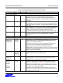
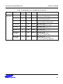
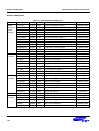
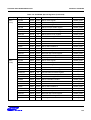
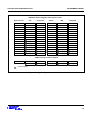
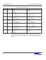
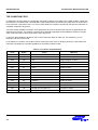
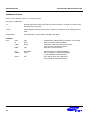
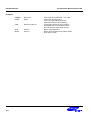
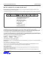
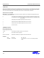
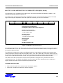
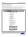
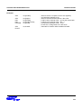
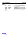
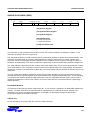
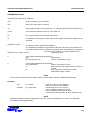
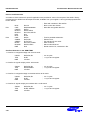
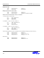
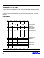
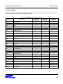
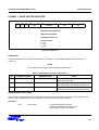
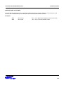
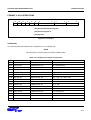
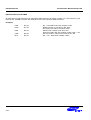
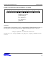
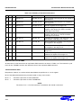
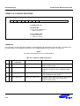
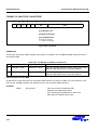
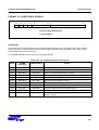
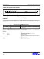
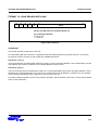
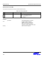
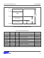
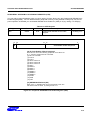
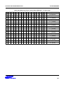
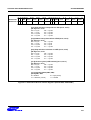
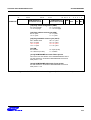
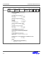
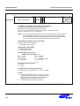
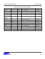
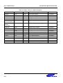
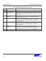
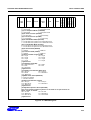
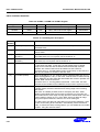
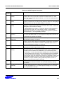
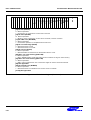
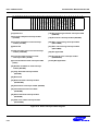
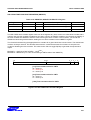
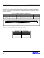
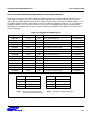
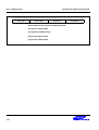
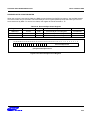
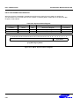
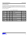
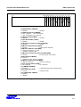
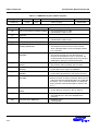
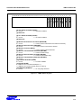
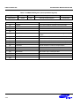
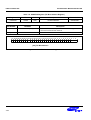
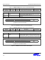
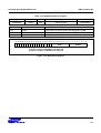
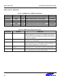
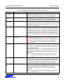
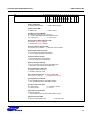
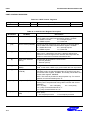
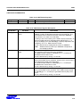
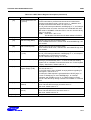
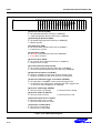
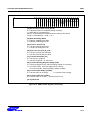
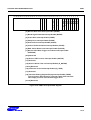
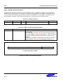
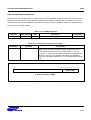
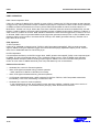
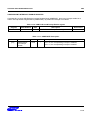
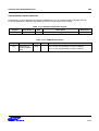
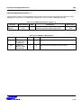
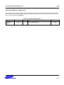
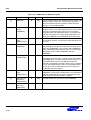
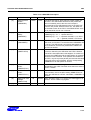
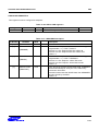
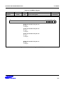
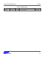
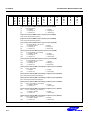
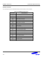
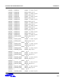
Table 6-12. HSTAT Register Description
Bit
Number
Bit Name
Description
[3:0]
Rx remaining bytes
(RxRB)
(RxRB + 1) indicates how many data bytes are valid in a 1-word or 4-word
boundary when the receiver has received a complete frame. In 1-word
transfer mode, the RxRB value is either 0, 1, 2, or 3. In 4-word mode, it is
0, 1, ..., 14, or 15.
[4]
Tx frame complete
(TxFC)
This status bit is automatically set to '1' when the two conditions are met:
1) there is no data in the Tx FIFO, and 2) either an abort or a closing flag is
transmitted. You can clear this bit by writing '1' to this bit.
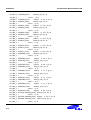
[5]
Tx FIFO available
(TxFA)
If this bit is '1', the data to be sent can be loaded into the HTxFIFO
register. In 1-word transfer mode, the TxFA status bit is set to '1' when the
first register of the HTxFIFO is empty.
In 4-word transfer mode, TxFA = '1' when the first four 32-bit registers of
the HTxFIFO are empty. The TxFA status condition is automatically
cleared when HTxFIFO is no longer available. During DMA Tx operation,
this bit is always ’0', so not generating interrupt.
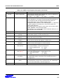
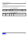
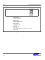
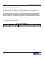
[6]
Tx clear-to-send
(TxCTS)
The nCTS input is projected to this status bit. If the level at the nCTS input
pin is Low, this status bit is'1'. If nCTS input pin is High level, TxCTS is '0'.
This bit does not generate an interrupt.
[7]
Tx stored clear-to-send
(TxSCTS)
This bit is set to '1' each time a transition in nCTS input occurs. You can
clear this bit by writing '1' to this bit.
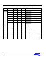
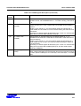
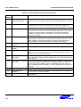
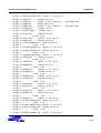
[8]
Tx under-run (TxU)
When the transmitter runs out of data during a frame transmission, an
underrun occurs and the frame is automatically terminated by transmitting
an abort sequence. The underrun condition is indicated when TxU is '1'.
You can clear this bit by writing a '1' to this bit.
[9]
Tx Good Frame (TxGF)
This bis is set to “1” whenever a frame is successfully transmitted. This is
independent of TxFIFO state. Refer to TxFC.
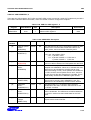
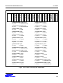
[10]
Rx FIFO available
(RxFA)
This status bit indicates when the data received can be read from the Rx
FIFO. When RxFA is '1', it indicates that data (other than an address or a
final data word) is available in the HRXFIFO. In 1-word transfer mode,
RxFA bit set to '1' when received data is available in the last FIFO register.
In 4-word transfer mode, it is set to '1' when the data received is available
in the last four 32-bit FIFO registers. Even if the data reside in FIFO for
only two words, when the Last bit is set, Rx FIFO is regarded as valid. (The
received data available condition is cleared automatically when the data
received is no longer available.) During DMA Rx operation, this bit is
always '0', so does not generate an interrupt.
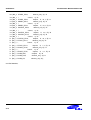
[11]
Rx flag detected (RxFD) This bit is set to '1' when the last bit of the flag sequence is received. This
bit generates an interrupt if enabled. You can clear this bit by writing a
'1' to this bit.
[12]
Rx data carrier detected The DCD status bit mirrors the state of the nDCD input pin. If nDCD input
(RxDCD)
pin is low, this status bit is '1'. If nDCD input pin is High, it is '0'. This bit
does not generate an interrupt.
6-33