1
US 6,810,373 B1
5
6
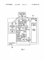
processes each bus cycle command from the I55 400 by
translating that commnand into pin level signals on simu
lated system bus 700, Which accurately represent the elec
trical signals that the actual CPU simulated by the I55 400
When a softWare instruction is executed by the I55 400
that accesses an address in either the peripheral devices 834
or the ROD 808, it issues the bus cycle command to the
BFM 802. When the bus cycle command is for an address in
the ROD 808, the BFM 802 translates the bus cycle com
mand into pin-level activity on the bus 700. The simulation
of the ROD 808 responds to this activity on bus 700. The
pin-level hardWare response of the ROD 808 is translated
Would issue. The BFM 802 is connected With the hardWare
model 804 via the hardWare modeled system bus 702 in the
logic simulator 800. The hardWare model 804 connects With
the ROD 808 via the peripheral input/output nets 704. The
VPC 200 controls the operation of the I55 400, the logic
back to the command level by the BFM 802, Which provides
the bus cycle command response to the I55 400. During this
bus cycle command, the SIU 812 manages all commands,
simulator 800, and the BFM 802. The VPC 200 handles
initialiZation and provides a graphical user interface for
control.
accesses, and translations.
When the I55 400 issues a bus cycle command for an
The hardWare model 804 of a microcontroller is a con
ventional and Well-knoWn device in the pertinent art. The
address in the peripheral devices 834, the hardWare model
804 models the peripheral devices 834. The BFM 802
translates the bus cycle command into pin level activity on
hardWare model 804 is built With an actual hardWare inte
grated circuit microcontroller chip commonly used by
designers for design veri?cation and debugging. The hard
Ware model 804 is interfaced With the logic simulator 800 to
act as a model of the microcontroller in system simulation,
using its internal actual integrated circuit device to provide
accurate functional behavior. The microcontroller, modeled
20
by the hardWare model 804, is the representative of Widely
used microcontrollers. The hardWare model 804 comprises a
CPU 814 that executes an instruction stream during
operation, the peripheral devices 834 that provide special
iZed functionality such as communication ports into and out
of the microcontroller, and the SIU 824 that interfaces the
CPU 814 and/or the peripheral devices 834 With an external
bus for integration of memory and/or other devices external
to the microcontroller. The external system bus in the
hardWare model of this microcontroller is the hardWare
modeled system bus 702.
25
ity by issuing an interrupt request, the pin-level activity of
the hardWare model 804 is detected by slave SIU 822, and
is translated into a command for the I55 400. LikeWise,
pin-level bus cycle signals on the hardWare model system
30
As a result, the VSP 240 is a simulation model With the
35
CPU and acts as a safe storage to store both instructions and
data for the CPU. Both the data cache 816 and the instruc
tions cache 818 have 4-Kbyte of memory and are tWo-Way
40
set associative to alloW rapid core access to data and
instructions. The CPU 814 also have tWo types of memory
management units (MMU): an IMMU 817 for instructions,
and a DMMU 819 for data. These MMUs provide memory
management, cache control, memory access protection, and
effective-to-physical address translation. The caches 816,
bus 702 are detected by the slave SIU 822 Which, in turn,
drives the ROD 808 in the logic simulation 800. This activity
simulates execution of the DMA cycle.
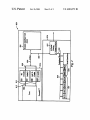
The microcontroller modeled by the hardware model 804
in the preferred embodiment is a Motorola MPC860, Whose
internal block diagram is shoWn in FIG. 2. The CPU 814
contains tWo types of caches: an instruction cache 816, and
a data cache 818. A cache memory is another type of
memory consisting of fast memory located closest to the
the hardWare model system bus 702, driving the hardWare
model 804 through the separate slave SIU 822 of the BFM
802. Response from the hardWare model 804 is translated
into the command level by the BFM 802, Which provides the
bus cycle response back to the I55 400.
Activity on the peripheral devices 834 is seen directly by
both the hardWare model 804 and the logic simulation 800
via the peripheral input/output nets 704. When any of the
hardWare-modeled peripheral devices 834 initiates an activ
45
speed of operation of the I55 400 and With the accuracy of
the hardWare model 804. In normal operation, the logic
simulator 800 and 155 400 must remain coupled
(synchroniZed in simulated time) to insure that all the
causeeffect relationships of the signalkevents betWeen the
tWo are preserved and accurately modeled. Then softWare
execution by the simulated system is timing accurate, so
hardWare and softWare execution times can be compared.
This coupled operation is relatively sloW because it is
limited by the speed of logic simulator 800.
Higher speed is achieved by coupling the I55 400 to the
logic simulation 800 only during those necessary bus cycles.
Thus, the I55 400 and the logic simulation 800 are not
818, and MMUs 817, 819 are connected to a CPU 815 core
synchroniZed in time during periods of little interaction
via the instruction buses 811 for instructions and 812 for the
betWeen the I55 400 instruction execution and the peripheral
devices 834 or the ROD 808; in particular, When the I55 400
executes the initialiZation of the operating system softWare.
As a result, Without being held back by the much sloWer
data. These caches and MMUs are of the conventional sort
Widely used in modem CPUs and are Well-knoWn in the
pertinent art.
The MPC860’s peripheral devices 834 are in the form of
a communications processor module (CPM), Which contains
an array of serial communication controllers (SCC) 835, and
serial management channels (SMC) 836, Which can conduct
a direct memory access (DMA) 837, and other peripheral
devices, via a peripheral bus 839 under the local control of
speed of the simulator 800, the I55 400 can run at its full
speed, Which may be hundreds of thousands of instructions
per second. But during the cycles in Which the I55 400
55
issues a bus cycle command to a location modeled by an
Manual published by Motorola Co., MPC860UM/AD pub
element in the logic simulation 800, the I55 400 and the
logic simulation 800 are temporarily re-synchroniZed for the
duration of the simulation of the bus cycle. Coupling and
uncoupling may also be controlled manually by the user
through the VPC 200.
Operation When the HardWare Model’s CPU Cannot Be
lished in July 1998. Any person of ordinary skill in the art
Turned Off.
a dedicated peripheral microcontroller and program Read
Only-Memory (ROM). The detailed description of the
MPC860 is described in the MPC860 PoWer QUICC User
60
Sometimes the microcontroller chip’s CPU 814, used in
can use the manual to program and operate the microcon
troller MPC 860 according to the instructions disclosed by
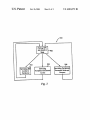
the invention. Combining the I55 400 and the HardWare
Model 804 to Form Single Accurate and High Performance
Model.
65
the hardWare model 804 cannot be disabled. Then, substi
tuting the I55 400 for the hardWare model of the CPU 814
Would be impossible simply because the hardWare model’s
CPU 814 activity could not be replaced by the activity of the