Download BRAVO 500 - Set Up Users
Transcript
EN
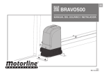
BRAVO500
USER'S AND INSTALLER'S MANUAL
v2.1
REV. 11/2014
00. CONTENT
01. SAFETY INSTRUCTIONS
INDEX
STANDARDS TO FOLLOW
01. SAFETY INSTRUCTIONS
ATTENTION:
STANDARDS TO FOLLOW
1B
02. PACKAGE
INSIDE PACKAGE
2A
03. OPERATOR
OPEN COVER
2B
UNLOCK OPERATOR
3A
TECHNICAL SPECIFICATIONS
3B
04. INSTALLATION
INSTALLATION SITE PREPARATION
4A
SITE INSTALLATION – CREATE FOUNDATION
4A
SITE INSTALLATION – EXISTING FOUNDATION
5A
APPLICATION OF MOTOR
5B
INSTALLATION OF STEEL GEAR RACK
6A
INSTALLATION OF NYLON GEAR RACK
7A
INSTALLATION OF PLATES THE LIMIT SWITCHES
8A
CLUTCH ADJUSTMENT
8B
MAP OF INSTALLATION
9
05. TROUBLESHOOTING
FINAL CONSUMERS INSTRUCTIONS
10
SPECIALIZED TECHNICIANS INSTRUCTIONS
10
• To ensure the safety of people, it is important that you read all the following instructions. Incorrect installation or incorrect use of the product can cause physical injury
and material damage.
• Keep these instructions in a safe place for future reference.
• This product was designed and produced strictly for the use indicated in this manual.
Any other use, not expressly indicated here, could compromise the good condition/operation of the product and/or be a source of danger.
• ELECTROCELOS S.A. is not responsible for the improper use of the product, or other
use than that for which it was designed.
• ELECTROCELOS S.A. is not responsible if safety standards were not taken into account when installing the equipment, or for any deformation that may occur to it.
• ELECTROCELOS S.A. is not responsible for the safety and proper operation when
using components not sold by them.
• Do not make any modifications to the operator components and / or their accessories.
• Before installation unplug the automatism from the source of power.
• The installer must inform the client how to handle the product in case of emergency
and provide this manual to user.
• Keep remote controls away from children, to prevent the automated system from
being activated involuntarily.
• The customer shall not, under any circumstances, attempt to repair or tune the operator .Must call qualified technician only.
• Connect the automatism to a 230V plug with ground wire.
• Operator for outdoor and indoor use.
06. COMPONENTS TEST
SCHEMES FOR CAPACITORS
11A
07. MAINTENANCE
MAINTENANCE
11B
2A
EN
2B
EN
02. PACKAGE
03. OPERATOR
OPEN COVER
INSIDE PACKAGE
Inside the package you will find the following components:
01• 01 motor Bravo500
02• 02 release keys
03• 04 screws DIN912 M5x10
04• 04 fixing screws to the plate
05• 04 fixing screws to the ground
06• 01 fixation plate
During installation you will need
to open the motor cover, to access
various components on the inside. For
this, loosen the 2 screws identified
with (A) until the cover is free to be
removed.
07• 02 fixation plate of the limit switches
08• 01 user's manual
09• 02 photocells
10• 02 remote controls
11• 01 Control board
A
08•
01•
03•
06•
05•
04
04•
07•
02•
01
Electronic components of the kit:
09•
10•
11•
A
02
226mm
A
385mm
380mm
03
3A
EN
05
3B
EN
03. OPERATOR
03. OPERATOR
UNLOCK OPERATOR
TECHNICAL SPECIFICATIONS
To open manually the gate in case of electric power failure or in case of damage, follow
the below steps:
The specifications of the automatism BRAVO 500 are as follows:
• Power Supply
07
01 • Open the protection cover to acess
the key hole for the release.
02 • Insert the key and turn it 90°.
BRAVO500/110
AC 230V 50Hz
AC 110V 60Hz
• Power
280W
280W
• Current
0,8A
0,8A
• Speed
0,16 m/sec
0,16 m/sec
• Thermal protection
120ºC
120ºC
• Force
1200N
1200N
>-45°C a <65°C
>-45°C a <65°C
• Capacitor
8µF
25µF
• Noise level
IP44
IP44
• Working frequency
25%
25%
<56_db
<56_db
• Working temperature
06
BRAVO500
• IP protection
• Thermal reset
2min to complete cycle 2min to complete cycle
• Maximum weight of leaf
• Maximum size of leaf
500kg
500kg
7m
7m
The dimensions of automatism BRAVO 500 are the following:
186.5mm
08
145mm
09
319.5mm
03 • Pull the lever towards the outside, and you can now open/close the gate manually.
329mm
So that the automation will operate normally, close the unlock and turn the key to the
original position. Close the cover (06) to finish, make a move in order to confirm the
functioning of the automation.
76mm
255mm
4A
EN
4B
EN
36mm
139mm
183mm
271mm
10
04. INSTALLATION
04. INSTALLATION
INSTALLATION SITE PREPARATION
SITE INSTALLATION – CREATE FOUNDATION
To ensure full operation of the automatism, pay attention the following recommendations:
• Read the entire manual at least once giving special attention to all notices marked
with
;
• Check that the gate structure is sufficiently resistant;
• The gate should be very well leveled and have a uniform movement without irregular
friction during the full course;
• The foundation to create in step 02 of page 4.B should be very resistant to support the
mounting screws of the plate;
• It is recommended that all locksmith works are carried out before proceeding with
installation of the automatism.
• Check if the size and weight of the gate correspond with the presented with the
technical data of the motor (p. 3B).
13
12
02 • Fill the hole with fresh concrete and
smooth the top part where you will fix the
plate.
03 • Attach the screws to the plate with
nut and counter nut as shown in picture
13.
INSTALLATION SITE PREPARATION
NOTE:
For correct operation of the automatism, it is necessary to pay attention to the dimensions
given in the following images. Also check that the fixation plate is parallel to the gate.
DETAIL 11
14
04 • Insert the plate with screws in the concrete while it is still fresh and level it
horizontally with a level. Also align it parallel to the gate, keeping a distance of 60mm
between them, as visible in picture 16.
60mm
95mm
15
60mm
305mm
11
16
01 • Make a hole in the ground to create a foundation in concrete. The dimensions
shown are these recommended to create the foundation. You must leave tubes in the
middle of the hole for the passage of cables for power and accessories, as shown in the
detail of image 11.
5A
EN
05 • Let the concrete dry so that the plate stays well fixed.
5B
EN
17
04. INSTALLATION
04. INSTALLATION
SITE INSTALLATION – EXISTING FOUNDATION
APPLICATION OF MOTOR
In case there is already a foundation at the installation site, proceed as below:
60mm
18
60mm
19
01 • Place the fixing plate on top of the foundation and align it parallel to the gate, keeping a distance of 60mm between them, as visible in Figure 19.
24
01 • Remove the side covers of the motor
by pulling them up.
25
02 • Place the motor in the fixing plate.
DETAIL 26
63mm
20
02 • Mark the place to make the holes for
the bushings. Must make the mark at the
center of the oval holes of the plate.
22
21
03 • Drill four holes with Ø18mm on foundation. Place M10 steel anchors on the
holes.
26
03 • Align it parallel to the gate leaving a distance of 63mm between them, as visible in
the image 26. Oval holes of the motor should be centered with the threaded holes in the
fixing plate, as visible on DETAIL 26.
23
04 • Place the fixing plate on the foundation in cement respecting the distances of
image 19. Use a level to levelit horizontally and fasten it with M10 screws.
6A
EN
27
04 • Fix it with the M10 x 25 screws
provided.
6B
EN
28
05 • Reassemble the motor's side covers
to hide the screws.
04. INSTALLATION
04. INSTALLATION
INSTALLATION OF STEEL GEAR RACK
INSTALLATION OF STEEL GEAR RACK
Place the gate in the open position and unlock the motor! (p.03A). )
C
DETAIL 29
A
B
34
29
01 • Place spacers in all holes of the rack to fix it to the gate. Must put them in the
center of the oval holes in the rack, as shown in Figure 29, so you can adjust the rack at
the end of the installation if necessary.
31
30
02 • Place a piece of rack on top of the pinion and level it horizontally with a level.
05 • Close the gate a bit, so that the rack is not being supported on the pinion anymore
and apply another piece of rack (A). To synchronize the teeth with the piece already
installed, use an additional piece of rack (B) and place it under the union of the other
two, holding them with clamps (C).
35
03 • Weld the spacer on top of the pinion.
06 • Open the gate to support the point of
the new piece of rack on top of the pinion
and weld the spacer.
36
07 • Remove the piece of auxiliary rack
and open the gate until the other end
of the rack stands on top of the pinion.
Weld the spacer.
08 • Repeat the steps 5-7 for each meter of the rack, until you reach the end.
09 • Manually, test the movement of the gate with all racks already installed and weld
the remaining spacers. In case of finding some friction between the rack and pinion,
adjust the rack on the oval holes with screws.
32
During the course of the gate, all elements of the rack must mesh properly with the
pinion (space 1.5mm)!
The spacers can't be welded to the rack! And also the pieces of rack with one another.
Do not use mass or other types of lubricant between rack and pinion!
33
04 • Close the gate a bit until the other end of the rack rests on top of the pinion and
weld the other spacer to the gate.
7A
EN
7B
EN
04. INSTALLATION
04. INSTALLATION
INSTALLATION OF NYLON GEAR RACK
INSTALLATION OF NYLON GEAR RACK
Place the gate in the open position and unlock the motor! (p.03A)
B
A
41
04 • Close the gate a bit, so that the rack is not being supported on the pinion
anymore and apply another piece of rack (A), fitting it into the rack already installed
(B), as you can see in detail of image 41.
37
38
01 • Place a piece of rack on top of the
pinion and level it horizontally with a level.
02 • Fasten the support of the rack over
the pinion to the gate.
42
05 • Open the gate until the other end of
the new rack is on top of the pinion rack
and fasten it to the gate.
43
06 • Open the gate until the other end
of the rack stands on top of the pinion.
Fasten it to the gate.
07 • Repeat the steps 4-6 for each rack piece until you reach the end.
39
During the course of the gate, all elements of the rack must mesh properly with the
pinion!
All rack supports must be weld at the gate.
Do not use mass or other types of lubricant between rack and pinion!
40
03 • Close the gate a bit until the other end of the rack rests on top of the pinion and
fasten the other support.
8A
EN
8B
EN
04. INSTALLATION
04. INSTALLATION
CLUTCH ADJUSTMENT
INSTALLATION OF PLATES THE LIMIT SWITCHES
To start the disassembly of the control board, disconnect the power and have
maximum care when handling it.
Place the gate in the open position and unlock the motor! (p.03A)
01 • Unbolt the screws and remove the
cover, as explained in p. 02B.
1
02 • You must now access the adjusting
screw of the clutch.
For this remove the cover of the control
board box. Loosen the 2 screws of the
control board and remove it from the box.
Now loosen the 2 screws that fix the box
of control board to the motor and remove
it as well.
2
3
44
45
01 • Place the opening limit-switch plate in the rack so that it can trigger the limit-switch
of the motor before the gate gets to opening stopper. The plate must activate the spring
of the limit-switch as visible in the image 45.
48
03 • Adjust the screw in the upper part
of the motor. Use a 6mm hexagon key as
shown in image 49.
How to make the adjustment:
•Irreversibility of the motor.
Do a test to the motor’s irreversibility. For
that, just try to move the gate manually
with the motor locked. If the gate is
moving, it is necessary to adjust the screw
by rotating it clockwise (+).
46
02 • Put the DIN912 M5 x 12 screws supplied
with the accessories until the limit-switch
plate is fixed to the rack.
47
03 • Move the gate to the closed position
and repeat steps 1 and 2 to fix the closing
limit-switch plate to the rack.
49
The tuning must achieve a balance between the gate's irreversibility and the
engines power.
Any adjustment must always be made lightly, always experimenting the motor's
operation with every adjustment until you achieve the necessary balance
between the irreversibility of the motor and the strength of idle speed.
The limit-switch plates must be tuned for the gate stop before it hits the opening and
closing stoppers. Manualy test the activation of the limit-switches with the gate unlocked, before you connect it to the electric power, in order to prevent problems due to
bad installation.
9A
EN
•Idle speed of the motor
If the gate does not move at idle speed,
it means that the screw is too much
tightened. Rotate it counterclockwise
(-) until the motor moves the gate at idle
speed.
9B
EN
04. INSTALLATION
MAP OF INSTALLATION
• FLASH LAMP
• ANTENNA
• CONTROL
BOARD
• BRAVO500
• PHOTOCELL
• PHOTOCELL
• KEY SELECTOR
LEGEND:
• Cables of connection
It is important to use stoppers on the opening and closing of the gate. If this is not
respected, there may be danger of the gate open too much in manual mode and jump
out of the rail.
It is important to use junction boxes for connections between motors, components
and control board. All cables enter and exit under the junction box and box of
control board.
10
EN
05. TROUBLESHOOTING
SPECIALIZED TECHNICIANS INSTRUCTIONS
FINAL CONSUMERS INSTRUCTIONS
Problem
• Motor
doesn't work
• Motor
doesn’t move
but makes
noise
Procedure
Behavior
Procedure II
• Consult a qualified
MOTORLINE technician.
Discovering the origin of the problem
• Make sure you
have 230V power
supply connected to
control board and if it
is working properly.
• Still not working
• Unlock motor and
move the gate by
hand to check for
mechanical problems
on the movement.
• Encountered
problems?
• Consult a qualified gates
technician.
1 • Check motion axis and associated motion systems related with the motor and the gate to find out what is the problem.
• The gate moves
easily?
• Consult a qualified
MOTORLINE technician.
1 • Check capacitor, testing
operator with a new one;
1 • Check if there is any
obstacle in front of the
photocells;
2 • Check if any of the control
devices (key selector, push
button, video intercom, etc.)
of the gate
are jammed and sending
permanent signal to control
unit;
3 • Consult a qualified
MOTORLINE technician.
All MOTORLINE control boards have LEDs that
easily allow to conclude which devices are
with anomalies.
All safety devices LEDs (DS) in normal
situations remain On.
All "START" circuits LEDs in normal situations
remain Off
1 • Open control board and check
if it has 230V power supply;
2 • Check input fuses of the
control board;
• Gate opened but
• Motor opens • Unlock motor and
but doesn’t
move the gate by hand didn’t close again..
close
to closed position.
Lock motor again
and turn of power
supply for 5 seconds.
Reconnect it and send
order to open gate
using transmitter.
3 • Disconnect the motor from
control board and test them by
connecting directly to power
supply in order to find out if they
have problems (see page 11A).
2 • If capacitors are not the
problem, disconnect motor from
control board and it them by
connecting directly to power
supply in order to find out if it has
problems (see page 11A);
If LEDs devices are not all On, there is some
security systems malfunction (photocells,
safety edges), etc.
If "START" circuits LEDs are turn On, there is a
control device sending permanent signal
A) SECURITY SYSTEMS:
1 • Close with a shunt all safety systems
• Motor opens • Unlock motor and
but doesn’t
move gate by hand to
close.
check for mechanical
problems on the gate.
4 • If the motor works, problem is
on the control board.
Pull it out and send it to our
MOTORLINE technical services
for diagnosis;
3 • If the motor works, the
problem is from control board.
Pull it out and send it to our
MOTORLINE technical services
for diagnosis;
on the control board (check manual of the
control board in question).
If the automated system starts working
normally check for the problematic device.
2 • Remove one shunt at a time until you find
the malfunction device.
3 • Replace it for a functional device and
check if the motor works correctly with all
the other devices. If you find another one
defective, follow the same steps until you find
all the problems.
5 • If the motor doesn’t work,
remove them from installation
site and send to our MOTORLINE
technical services for diagnosis.
4 • If the motor doesn’t work,
remove them from installation
site and send to our MOTORLINE
technical services for diagnosis.
2 • If the LED turned Off, try reconnecting one
device at a time until you find the defective
device.
NOTE:
In case procedures described in sections A)
and B) don’t result, remove control board and
send to our technical services for diagnosis;
B) START SYSTEMS:
1 • Disconnect all wires from START terminal
input.
• Encountered
problems?
• Consult a qualified gates
technician.
1 • Check all motion axis and associated motion systems related with the gate to find out what is the problem.
• The gate moves
easily?
• Consult a qualified
MOTORLINE technician.
1 • Check capacitors, testing with
new capacitors.
2 • If capacitors are not the
problem, disconnect motor
from control board and test it
by connecting directly to power
supply in order to find out if it is
broken;
3 • f the motor doesn’t work,
remove it from installation site
and send to our MOTORLINE
technical services for diagnosis.
4 • If motor work well and move
gate at full force during the
entire course, the problem is
from controller. Set force using
trimmer on the board. Make a
new working time programming,
giving sufficient time for opening
and closing with appropriate
force .
5 • If this doesn’t work, remove
control unit and send it to
MOTORLINE technical services.
(vehicles, people, etc).
NOTA: Setting force of the
controller should be sufficient
to make the gate open and close
without stopping, but should stop
and invert with a little effort from
a person.
In case of safety systems failure,
the gate shall never cause
physical damaged to obstacles
11
EN
06. COMPONENTS TEST
07. MAINTENANCE
SCHEMES FOR CAPACITORS
MAINTENANCE
To detect which components have problems during a sliding automatism installation,
sometimes it's necessary to conduct tests with a direct connection to a 230V power
supply. For this, it's necessary to interpose a capacitor on the connection so that the
motor can work (check the capacitor type to be used in the product's manual).
In the below diagram is shown how this connection must be made and how to merge
the different component wires..
• Check all screws of the automation
such as the fixing plate to the ground,
the plates of the limit switches, motor
and the gear rack.
NOTES:
• To perform the tests you don't need to remove the automatism from it's place, because
this way you can understand if the automatism, directly connected to the power, can
function correctly.
• The order of capacitor wires linked with the automatism wires are not important, as
long as you link, one to the Brown wire and the other to the Black one;
• The common wire of the motor must always be connected to the power supply;
• To reverse the automatism functioning direction, switch the Black wire with the Brown
wire of the automatism.
BRAVO500
Common(Blue)
51
•Check that the distance between rack
and motor remains unchanged and this
engages the teeth of the pinion of the
engine correctly (over time can happen
some distortion).
52
230V POWER
SUPPLY
•Lubricate all systems/axis of movement
of the gate. Lightly lubricate with spray
the rack and pinion.
Black
Brown
Ground wire
CAPACITOR
53
50
All tests must be performed by skilled technicians due to serious danger associated
with the misuse of electrical systems!!
These maintenance measures must be made every 6 months to maintain the good
functioning of the automatism.
12A
12B
EN
EN


