1
California Media Engineering Inc.
5000-AVD
Audio-Video Broadcast Delay
with built-in switching
Operations Manual
5000-AVD-OM Operations Manual Version 2.0.0
5000-AVD • Audio-Video Delay Operations Manual
• Cal Media Part Number: 5000-AVD-OM
• Document Version: 2.0.0
• Printed in U.S.A.
The information contained in this User Manual is subject to change without notice or obligation.
Copyright
© 2009-2010 California Media Engineering Inc. All rights reserved.
Contents of this publication may not be reproduced in any form without the written permission
of California Media Engineering Inc. Reproduction, distribution or reverse engineering of
copyrighted software and firmware is prohibited.
Notice
The material in this manual is furnished for informational use only. It is subject to change
without notice and should not be construed as a commitment by Cal Media. Cal Media assumes
no responsibility or liability for errors or inaccuracies that may appear in this manual.
Trademarks
•
is a registered trademark of Ross Video Limited.
•
is a trademark of California Media Engineering Inc.
•
DashBoard™ Control System is a registered trademark of Ross Video Limited.
•
All other product names and any registered and unregistered trademarks mentioned
in this manual are used for identification purposes only and remain the exclusive
property of their respective owners.
5000-AVD Operations Manual – Version 2.0.0
page 2 of 48
Important Regulatory and Safety Notices
Before using this product and any associated equipment, refer to the ―Important Safety Instructions‖
listed below so as to avoid personnel injury and to prevent product damage.
Products may require specific equipment, and /or installation procedures be carried out to satisfy
certain regulatory compliance requirements. Notices have been included in this publication to call
attention to these Specific requirements.
Symbol Meanings
This symbol on the equipment refers you to important operating and maintenance
(servicing) instructions within the Product Manual Documentation. Failure to heed this
information may present a major risk of damage or injury to persons or equipment.
The symbol with the word “Warning” within the equipment manual indicates a
potentially hazardous situation, which if not avoided, could result in death or serious
injury.
Warning
The symbol with the word ―Caution‖ within the equipment manual indicates a
potentially hazardous situation, which if not avoided, may result in minor or moderate
injury. It may also be used to alert against unsafe practices.
Caution
The symbol with the word ―Notice‖ within the equipment manual indicates a situation,
which if not avoided, may result in major or minor equipment damage or a situation
which could place the equipment in a non-compliant operating state.
Notice
This symbol is used to alert the user that an electrical or electronic device or assembly
is susceptible to damage from an ESD event.
ESD
Susceptibility
Important Safety Instructions
Caution
This product is intended to be a component product of the openGear™ 8300 series
frame. Refer to the openGear™ 8300 series frame User Manual for important safety
instructions regarding the proper installation and safe operation of the frame as well
as it’s component products.
Warning
Certain parts of this equipment namely the power supply area still present a safety
hazard with the power switch in the OFF position. To avoid electrical shock,
disconnect all A/C power cords from the chassis' rear appliance connectors before
servicing this area.
Warnin
g
Service barriers within this product are intended to protect the operator and service
personnel from hazardous voltages. For continued safety, replace all barriers after any
servicing.
Warning
This product contains safety critical parts, which if incorrectly replaced may present a
risk of fire or electrical shock. Components contained within the product’s power
supplies and power supply area, are not intended to be customer serviced and should be
returned to the factory for repair. To reduce the risk of fire, replacement fuses must be
the same type and rating. Only use attachments/accessories specified by the
manufacturer.
5000-AVD Operations Manual – Version 2.0.0
page 3 of 48
Maintenance/User Serviceable Parts
Routine maintenance to this openGear™ product is not required. This product contains no user
serviceable parts. If the module does not appear to be working properly, please contact Technical
Support using the contact information on the last page of this manual. All Cal Media openGear™
products are covered by a generous 5-year warranty and will be repaired without charge for materials or
labor within this period. Refer to the ―Warranty‖ and ―Repair Policy‖ sections in this manual for details.
Environmental Information
The equipment that you purchased required the extraction and use of natural resources for its
production. It may contain hazardous substances that could impact health and the environment.
To avoid the potential release of those substances into the environment and to diminish the need for the
extraction of natural resources, Cal Media encourages you to use the appropriate take-back systems.
These systems will reuse or recycle most of the materials from your end-of-life equipment in an
environmentally friendly and health conscious manner.
The crossed-out wheeled bin symbol invites you to use these systems.
If you need more information on the collection, reuse, and recycling systems, please contact your local
or regional waste administration.
You can also contact Cal Media for more information on the environmental performances of our
products.
5000-AVD Operations Manual – Version 2.0.0
page 4 of 48
Contents
Introduction........................................................................................................................................... 7
A Word of Thanks .............................................................................................................................................................. 7
Overview ............................................................................................................................................................................ 7
Block Diagram ................................................................................................................................................................... 8
Detailed Description ........................................................................................................................................................... 8
Video Processing ............................................................................................................................................................ 8
Audio Processing.......................................................................................................................................................... 10
Installation and Setup......................................................................................................................... 11
Static Discharge ................................................................................................................................................................ 11
Unpacking ........................................................................................................................................................................ 11
Rear Module Installation (Optional)................................................................................................................................. 12
Board Installation ............................................................................................................................................................. 13
Cable Connections ............................................................................................................................................................ 13
SD/MMC Memory Card Installation (Optional) .............................................................................................................. 14
Operation ............................................................................................................................................. 15
DashBoard™ Controls ..................................................................................................................................................... 15
Control Menus .................................................................................................................................................................. 15
Delay & System Menu .................................................................................................................................................. 16
Audio/Video Delay................................................................................................................................................... 16
System Video Format ............................................................................................................................................... 16
Genlock Timing ........................................................................................................................................................ 17
Output Embedded Audio Group Enable ................................................................................................................... 18
Proc Amps Menu .......................................................................................................................................................... 19
Delayed Input Proc Amp Controls ........................................................................................................................... 19
Aux Input Proc Amp Controls .................................................................................................................................. 20
Switch Menu ................................................................................................................................................................. 21
Censor Switch Configuration ................................................................................................................................... 21
Switching Video ....................................................................................................................................................... 22
Switching Audio ....................................................................................................................................................... 23
Outputs Menu ............................................................................................................................................................... 26
Output Video Selection ............................................................................................................................................ 26
Output Embedded Audio Group Enable ................................................................................................................... 27
Output Audio Channel Page Selection ..................................................................................................................... 27
Output Audio Selection (Mapping) .......................................................................................................................... 27
Output Audio Channel Controls ............................................................................................................................... 28
Output Audio Channel Resets .................................................................................................................................. 29
Stills Menu .................................................................................................................................................................... 30
Freeze AUX Input .................................................................................................................................................... 31
Still Images ............................................................................................................................................................... 31
Loading Still Images ................................................................................................................................................ 31
Saving Still Images to the SD/MMC card ................................................................................................................ 32
Deleting Still Images from the SD/MMC card ......................................................................................................... 34
Resetting the SD/MMC Card ................................................................................................................................... 34
5000-AVD Operations Manual – Version 2.0.0
page 5 of 48
Test Signals Menu ........................................................................................................................................................ 35
Video Test Patterns .................................................................................................................................................. 35
Audio Test Tones ..................................................................................................................................................... 36
Product Menu (Status).................................................................................................................................................. 37
Rear Module Menu ....................................................................................................................................................... 38
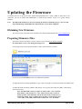
Updating the Firmware ...................................................................................................................... 39
Obtaining New Firmware ................................................................................................................................................. 39
Preparing Firmware Files ................................................................................................................................................. 39
Installing Firmware using Dashboard™ Version 3.0 ....................................................................................................... 40
Installing Firmware using Dashboard™ Version 2.0 ....................................................................................................... 41
Installing Firmware using a SD or MMC Memory Card.................................................................................................. 42
Troubleshooting Firmware Installation ............................................................................................................................ 43
Specifications ....................................................................................................................................... 44
5 YEAR LIMITED WARRANTY .................................................................................................... 46
Repair Policy ....................................................................................................................................... 47
5000-AVD Operations Manual – Version 2.0.0
page 6 of 48
Introduction
In This Chapter
This chapter contains the following sections:
• A Word of Thanks
• Overview
• Functional Block Diagram
• Detailed Description
A Word of Thanks
Congratulations on choosing Cal Media’s 5000-AVD Audio-Video Broadcast Delay with censor
switching for the openGear™ system. The 5000-AVD is part of a full line of media gear for
broadcast and production facilities.
Should you have a question pertaining to the installation or operation of your 5000-AVD, please
contact us at the numbers listed on the back cover of this manual, or through our web site at
www.calmedia.com.
Overview
The 5000-AVD is an Audio-Video Broadcast Delay providing a full 6.25 seconds of adjustable delay
for high definition signals.
16 embedded and 4 AES audio channels (20 channels total) can also be delayed independent of video
to allow for lip-sync correction. Censor switching is provided to eliminate objectionable material by
individually switching the video and each audio channel to alternate signals. Auxiliary A/V inputs
may be used for a ―safe‖ switch source as well as user defined images, freeze frame, black, other
audio channels, audio tones, and mute. Switching is performed via 2 GPI control inputs, and through
the openGear™ Dashboard™ control software (Windows, Linux and Mac platforms).
The 5000-AVD is designed for use in the openGear™ DFR-8300 series frames.
5000-AVD Operations Manual – Version 2.0.0
page 7 of 48
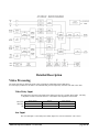
Block Diagram
Detailed Description
Video Processing
The 5000-AVD has two full frame audio-video synchronizers (SDI input and Aux SDI input).
For each input synchronizer, the audio is de-embedded and processed separately from the video and VANC data.
Video Delay Input
The SDI input is the main video input and is further processed by a variable delay buffer. The delay
is adjustable in frame increments from 0 to a maximum value dependent on the format.
HD-1080i
HD-720p
SD
60/59.94 Fps
6 seconds 10 frames
7 seconds 8 frames
30 seconds 28 frames
50 Fps
7 seconds 15 frames
8 seconds 28 frames
31 seconds 5 frames
24/23.98 Fps
7 seconds 22 frames
N/A
N/A
Table 1: Maximum Delay
Aux Input
The Aux SDI input is a non-delayed secondary input to be used as an alternate ―safe‖ source.
5000-AVD Operations Manual – Version 2.0.0
page 8 of 48
Video Proc Amps
Both the Delayed and Aux video signals have full color processing controls.
Setup:
adjusts the brightness of the picture
Video Level:
adjusts the contrast of the picture
Chroma:
adjusts the color saturation of the picture
Hue:
adjusts the tint or phase of the picture
Video Output Select
The video output select determines the primary path from which the video output originates.
Delay:
the output comes from the Delayed input synchronizer.
Aux:
the output comes from the Aux input synchronizer.
Black:
the output goes to black.
Test Signal:
the output comes from the internal test signal generator.
Still:
the output comes from one of four still image buffers.
Video Switching
Regardless of which video path is selected, the active picture portion can be switched to any other
source via Switch1 and Switch2 controls. These switches are engaged by the GPI inputs and/or the
control panel.
Note: The active picture is defined to be the actual picture information within the total signal. The
horizontal and vertical ancillary data space is not part of the active picture area, and is not affected
by the switch.
VANC Data
The video output will always pass the Vertical Ancillary Data from the primary path selected by the
Output Select.
When Switch1 or Switch2 are actively selecting an alternate video source, the output will continue to
pass the primary path’s VANC, and not the switched alternate source. This will preserve closed
caption data and timecode when switching the video away to another source.
Still Image Buffer
The 5000-AVD has four still image buffers which may be used as alternate sources for output video.
Each buffer may contain captured images from video, or images loaded from the SD/MMC card.
Images in each buffer may be saved to the SD/MMC card for future use.
Note: A memory card must be installed on the 5000-AVD card to save and load still images.
Memory Card
The 5000-AVD has a socket located at the front edge of the card to support SD or MMC memory
cards. The memory card is used for updating the firmware, and for storage of still images.
Compatible cards include MMC (multi-media card), SD (secure digital), and SDHC (high capacity).
To support still images, the SD/MMC cards must be formatted with a FAT16 or FAT32 file structure
(most cards greater than 64MB come pre-formatted as either FAT16 or FAT32). The 5000-AVD
conforms to the FAT32 specification so firmware and still image files may be exchanged easily with
most computers.
5000-AVD Operations Manual – Version 2.0.0
page 9 of 48
Audio Processing
The 5000-AVD contains a powerful audio processor providing individual mapping, level adjustments, and
clean switching of all 20 output channels.
Audio Delay Inputs
The AES1,AES2 and SDI-Embedded inputs are the main audio signals and are passed along with
video through an audio-video synchronizer. These signals are then processed by a variable delay
buffer. All 20 channels (16 Embedded + 4 AES) are delayed the same amount as the video signal,
but with an adjustable offset. The audio delay may be offset from video +/- 500ms
Aux Inputs
The Aux AES and Aux SDI-Embedded inputs are synchronized, non-delayed secondary inputs to be
used as alternate sources.
Audio Output Mapping
Full Audio Mapping is possible with the Audio Output Source control. Any source may be selected
for any output channel, including one source feeding multiple output channels. Simultaneous
Embedding and De-embedding is also realized with the Source control, since AES inputs may be
selected for Embedded outputs while Embedded inputs are selected for AES outputs. In addition to
the AES and Embedded inputs, four internal tone generators and silence are available as sources.
Audio Levels and Phase.
The mapping function also provides individual level adjustment and phase control for all output
channels. The level of each channel may be adjusted –40 to +20 dB, and the phase of each channel
may be inverted (180 degree phase shift).
Audio Switching
Regardless of the Audio Output Source settings, each output channel can be actively switched to any
other source via Switch1 and Switch2 controls. These switches are engaged by the GPI inputs and/or
the control panel. The switched outputs can also have different level and phase settings than those
used for the primary outputs.
5000-AVD Operations Manual – Version 2.0.0
page 10 of 48
Installation and Setup
In This Chapter
This chapter contains the following sections:
• Static Discharge
• Unpacking
• Rear Module Installation (Optional)
• Board Installation
• Cable Connections
• SD/MMC Memory Card Installation (Optional)
Static Discharge
Whenever handling the 5000-AVD and other related equipment, please observe all static discharge
precautions as described in the following note:
Static discharge can cause serious damage to sensitive
semiconductor devices. Avoid handling circuit boards in high
static environments such as carpeted areas, and when wearing
synthetic fiber clothing. Always exercise proper grounding
precautions when working on circuit boards and related
equipment.
ESD
Susceptibility
Unpacking
Unpack each 5000-AVD you received from the shipping container, and check the contents against the
packing list to ensure that all items are included. If any items are missing or damaged, contact your
openGear™ sales representative or Cal Media directly.
5000-AVD Operations Manual – Version 2.0.0
page 11 of 48
Rear Module Installation (Optional)
The 5000-AVD is compatible with the DFR-8310 and DFR-8320 series frames. The procedure for
installing the Rear Module in your openGear™ frame is the same regardless of the frame or module
used. However, a different module is required depending on the openGear™ frame you are using.
Rear Modules for the 5000-AVD
The Rear Module for the 5000-AVD depends on the openGear™ frame you are installing the card into.
• DFR-8310 series frames — When installing the 5000-AVD in the DFR-8310
series frames, the RM1-5000A Rear Module is required. The 5000-AVD is also
compatible with the DFR-8310-BNC frame.
• DFR-8320 series frames —When installing the 5000-AVD in the DFR-8320 series
frames, the Split Rear Module (RMS-5000A) or Full Rear Module (RM2-5000A) is
required.
Note: the Split Rear Module (RMS-5000A) may be used for SDI ONLY applications
(no AES inputs or outputs).
Installing the Rear Module
If you received a Rear Module with your 5000-AVD, you will need to install the module in your
DFR-8300 series frame before you can install the 5000-AVD in the frame, or connect cables to the
slot you have chosen for the 5000-AVD. Skip this section if you are installing the 5000-AVD in a
DFR-8310-BNC frame, or the Rear Module is already installed.
Use the following procedure to install the Rear Module in a DFR-8300 series frame:
1. Refer to the DFR-8300 series frame User Manual, to ensure that the frame is
properly installed according to instructions.
2. On the rear of the frame, locate the card frame slot.
3. Remove the Blank Plate from the rear of the slot you have chosen for the 5000AVD installation. If there is no Blank Plate installed, proceed to the next step.
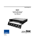
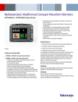
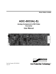
4. As shown in Figure 2-1, seat the bottom of the rear module in the seating slot at
the base of the frame’s back plane.
Screw Hole
Module Seating Slot
Figure 2-1. Rear Module Installation in a DFR-8310 Series Frame (5000-AVD not shown)
5000-AVD Operations Manual – Version 2.0.0
page 12 of 48
5. Align the top hole of the rear module with the screw hole on the top edge of the
frame back plane.
6. Using a Phillips driver and the supplied screw, fasten the rear module to the back
plane. Do not over tighten.
7. Ensure proper frame cooling and ventilation by having all rear frame slots covered
with Rear Module or blank metal plates. If you need blanks, refer to the chapter,
―Ordering Information‖ in your DFR-8300 series frame User Manual, and contact
your openGear™ sales representative.
This completes the procedure for installing the Rear Module in a DFR-8300 series frame.
Board Installation
Use the following procedure to install the 5000-AVD in a DFR-8300 series frame:
1. Refer to the User Manual of your DFR-8300 series frame to ensure that the frame
is properly installed.
2. After selecting the desired frame installation slot, hold the 5000-AVD card by the
edges and carefully align the card edges with the slots in the frame.
3. Fully insert the card into the frame until the rear connection plugs are properly
seated on the midplane and rear modules.
This completes the procedure for installing the 5000-AVD in a DFR-8300 series frame.
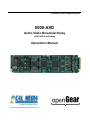
Cable Connections
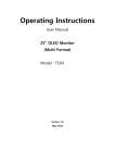
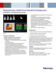
This section provides information for connecting cables to the installed Rear Module.
Note: When using a Split Rear Module (RMS-5000A) in the DFR-8320 series frames,
only the signals SDI In, GPI 1, AUX In, GPI 2, and SDI Out are connected.
Figure 2-2. Cable Connections for the RM1-5000A Rear Module
5000-AVD Operations Manual – Version 2.0.0
page 13 of 48
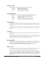
SD/MMC Memory Card Installation (Optional)
The memory card is used for updating the firmware, and for storage of still images. This section
provides information for installing a memory card on the 5000-AVD.
Hot Swappable
The memory cards are ―hot-swappable‖, which means they can be installed and removed while
the 5000-AVD card is powered and running, without causing interruption.
Compatible Cards
MMC (multi-media card)
SD (secure digital)
SDHC (secure digital high capacity)
Requirements
To support storage of still images, the SD/MMC cards must be formatted with a FAT16 or
FAT32 file structure (most cards greater than 64MB come pre-formatted as either FAT16 or
FAT32). The 5000-AVD conforms to the FAT32 specification so firmware and still image files
may be exchanged easily with most computers.
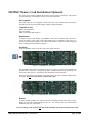
Installation
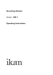
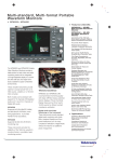
Locate the SD/MMC socket on the front edge of the 5000-AVD card.
Figure 2-3. SD/MMC Socket location.
The SD or MMC card should be positioned as shown in figure 2-3 with the corner notch nearest
the 5000-AVD’s card ejector. Using gentle pressure, carefully slide the memory card all the way
into the socket until it clicks. The memory card should now be locked into place.
If the socket will not accept the memory card then check if the card is backwards, upside-down,
or damaged. Do not force the memory card into the socket.
Figure 2-4. SD/MMC Memory Card Installed.
Removal
To remove the SD or MMC card, press the memory card further into the socket until it clicks.
Release the card and it should spring part way out. The memory card is now unlocked and
should slide easily out of the socket.
To prevent damage to the socket, do not pull on the SD/MMC card when it is locked into the socket.
5000-AVD Operations Manual – Version 2.0.0
page 14 of 48
Operation
DashBoard™ Controls
The 5000-AVD is controlled using the DashBoard™ Control System.
When the card is installed in an openGear™ frame, DashBoard™ will identify it as ―5000-A/V Delay”.
Open the selected card’s control panel by right-clicking the mouse and selecting ―Open‖.
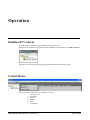
Control Menus
The Controls for the 5000-AVD are divided into six menus:
• Delay & System
• Proc Amps
• Switch
• Outputs
• Stills
• Test Signals
5000-AVD Operations Manual – Version 2.0.0
page 15 of 48
Delay & System Menu
Audio/Video Delay
The top section of the Delay & System menu contains the controls for setting the Audio/Video Delay.
The top line indicates the maximum amount of delay possible for the chosen video format.
Use the Seconds and Frames controls to select the amount of delay applied to the Audio and Video
signals. Note: these settings apply to both the Audio and Video signals.
Audio Delay Offset:
To correct for lip-sync errors in source materials or down stream equipment, a fixed offset can be
added to the audio path. The offset range is +/– 500ms (milliseconds) in 0.25ms steps.
System Video Format
The middle section of the Delay & System menu contains the control for setting the Video Format.
Use the System Format drop-down control to select the video format for the 5000-AVD.
The operator may choose from a list of standard formats and frame rates.
Note: input video signals must be the same format and frame rate as the output.
5000-AVD Operations Manual – Version 2.0.0
page 16 of 48
Genlock Timing
The lower middle section of the Delay & System menu contains controls for timing the 5000-AVD to
a genlock reference. The genlock reference does not have to be the same format as the 5000-AVD’s
system format, but it must be the same vertical rate. For example, a 59.94Hz 720p tri-level reference
may be used with a system format of 29.97 483i (NTSC).
Use the Genlock Select drop-down control to choose which signal will be used as the genlock
reference (The Product menu indicates the genlock status for the selected reference).
Note: the outputs may become unstable if there is no signal applied to the Aux Input and it is chosen
to be the Genlock Reference.
The following controls adjust the timing of the video frame synchronizers. Because of internal
processing delays (approx. 3+ lines), a phase setting of zero clocks / zero lines will guarantee one
frame of delay in the synchronizer.
Use the H-Phase control to adjust horizontal timing of the 5000-AVD’s video output with respect to
the selected genlock reference. This control adjusts the output in video clock increments, and may be
advanced or delayed 4095 clocks.
Use the V-Phase control to adjust vertical timing of the 5000-AVD’s video output with respect to the
selected genlock reference. This control adjusts the output in video line increments, and may be
advanced or delayed up to 1023 lines. This control may be used to advance the output some number
of lines to compensate for equipment delays down-stream.
Note: The maximum number of lines is dependant on the video format selected. Values greater than
the actual number of lines in one frame will roll-over to produce a minimum value. For example, in
NTSC a value of 530 will actually produce 5 (530 – 525).
Free Run Freq Adj is used to trim the output clock frequency when the 5000-AVD is in Free-run
mode. The range is +/- 8ppm (parts-per-million) which is equivalent to 0.0008%.
5000-AVD Operations Manual – Version 2.0.0
page 17 of 48
Output Embedded Audio Group Enable
The bottom section of the Delay & System menu contains controls for each embedded audio group on
the video output (these controls are also available under the Outputs menu).
Use the Group Enable buttons to enable (ON) or disable (OFF) each of the four audio groups.
Note: the 5000-AVD strips all ancillary embedded audio from the video input(s) and processes this
audio separately from video. In order to pass incoming embedded audio through the system, the
stripped audio must be re-embedded and the appropriate audio group(s) must be enabled.
5000-AVD Operations Manual – Version 2.0.0
page 18 of 48
Proc Amps Menu
Delayed Input Proc Amp Controls
The top section of the Proc Amps menu contains controls for adjusting the delayed video input.
Note: these controls apply to the video signal after it has been delayed, but before images are
captured for stills or freezing.
The Proc Amp Controls button is used to enable or disable all four Proc Amp controls.
When set to ON, the Proc Amp controls are active. When set to OFF, the Proc Amp controls are
bypassed (unity gain) and any control settings are ignored.
Use the Setup control to adjust the video signal’s brightness.
Use the Video Level control to adjust the video signal’s contrast.
Use the Chroma control to adjust the video signal’s color saturation.
Use the Hue control to adjust the video signal’s color hue (or chroma phase).
Use the Hue Mode control to select which method is used to calculate hue.
The Component Hue setting calculates the video hue based on equal scaling of the x,y color
space. This method is typically used in component digital equipment.
The Composite Hue setting calculates the video hue based on the unequal scaling of
NTSC/PAL color space. This method more closely resembles a traditional NTSC hue
control.
Clicking on the Default button will set all four Proc Amp controls to their default values (unity gain).
5000-AVD Operations Manual – Version 2.0.0
page 19 of 48
Aux Input Proc Amp Controls
The bottom section of the Proc Amps menu contains controls for adjusting the Aux video input.
Note: these controls apply to the video signal before images are captured for stills or freezing.
The Proc Amp Controls button is used to enable or disable all four Proc Amp controls.
When set to ON, the Proc Amp controls are active. When set to OFF, the Proc Amp controls are
bypassed (unity gain) and any control settings are ignored.
Use the Setup control to adjust the video signal’s brightness.
Use the Video Level control to adjust the video signal’s contrast.
Use the Chroma control to adjust the video signal’s color saturation.
Use the Hue control to adjust the video signal’s color hue (or chroma phase).
Use the Hue Mode control to select which method is used to calculate hue.
The Component Hue setting calculates the video hue based on equal scaling of the x,y color
space. This method is typically used in component digital equipment.
The Composite Hue setting calculates the video hue based on the unequal scaling of
NTSC/PAL color space. This method more closely resembles a traditional NTSC hue
control.
Clicking on the Default button will set all four Proc Amp controls to their default values (unity gain).
5000-AVD Operations Manual – Version 2.0.0
page 20 of 48
Switch Menu
The 5000-AVD contains two programmable switches that can be used to switch the video, audio or both signals to
avoid objectionable material. Switch 1 and Switch 2 can be externally controlled by BNC connectors GPI-1 and GPI-2.
A closure to ground on either BNC will activate the corresponding switch.
Censor Switch Configuration
The top section of the Switch menu contains controls for configuring Switch 1 and Switch 2.
The Enable check boxes allow the GPI input BNCs to externally control Switches 1 and 2.
When Switch 1 Enable is checked, then a closure to ground on the GPI-1 BNC will activate Switch 1.
When Switch 2 Enable is checked, then a closure to ground on the GPI-2 BNC will activate Switch 2.
The Mode dropdown controls configure how each switch behaves.
In Instant mode, the switch activates simultaneously with the GPI closure
(Delay – Reaction Time is ignored).
In Delayed mode, the activation of the switch is delayed by the programmed Audio/Video
Delay time (see Delay & System menu). This allows the switch to activate in time with the
delayed Audio/Video output.
In this mode the Delay – Reaction Time control is used to advance the start time of the
switch activation. This feature is used to compensate for human response time in recognizing
an objectionable incident. The Reaction Time has a range of 0 to 3 seconds in 0.1 second
steps.
The Delayed mode is designed for censoring applications where profanity and other
objectionable material must be removed. In this mode, the operator monitors the input source
(non-delayed). When an incident occurs the operator immediately engages a GPI-switch and
holds the GPI-switch until the incident has passed. Since the operator may not recognize the
incident until after it has occurred, a reaction time is programmed to compensate for this.
When viewing the delayed A/V outputs, the main program will switch away to some other
―safe‖ material before the offending incident occurs and will switch back to the main
program after the incident is over.
The PREVIEW buttons can be used to test each Switch’s configuration, instead of using the GPI.
PREVIEW ON engages the Switch as if the GPI port has a closure to ground.
PREVIEW OFF releases the Switch as if the GPI port is open.
5000-AVD Operations Manual – Version 2.0.0
page 21 of 48
Switching Video
The next section of the Switch menu contains controls for switching the Video signal.
Use the Switch Select drop-down control to assign a switch to the video path.
None
Switch 1
Switch 2
Both
= Video switching is disabled.
= Video controlled by Switch 1.
= Video controlled by Switch 2.
= Video controlled by both
Switch 1 and Switch 2.
Use the Video Source for Switch drop-down control to select a ―safe‖ source when switching the
video. The selected signal will become the video output when a video switch in engaged.
Delay
Aux
Black
Test Pattern
= Delayed Video input.
= Aux Video input.
= Black Video (0 IRE).
= defined by Video Test Pattern control
(see Test Signals menu).
Freeze FRM = Full Frame Freeze of the output video
while the switch is active.
Freeze FLD = Field mode Freeze of the output video
while the switch is active.
Still # FRM = Display Full Frame Still image
(see Stills menu).
Still # FLD
= Display Field mode Still image
(see Stills menu).
Note: Only the active portion of video is switched when engaged. All ancillary data from the main
program (Closed Captions, Time Code, etc) will remain undisturbed.
5000-AVD Operations Manual – Version 2.0.0
page 22 of 48
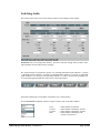
Switching Audio
The bottom section of the Switch menu contains controls for switching the Audio signals.
Destination refers to the output audio channel. The source and Gain settings will be routed to these
output channels when an audio switch is engaged.
The Audio Channels are organized in groups of 4, including Embedded Audio channels 1-4 (Group
1), Embedded Audio channels 5-8 (Group 2), Embedded Audio channels 9-12 (Group 3), Embedded
Audio channels 13-16 (Group 4), and AES audio channels 1-4 (AES). Each of these groupings may
be accessed through the thumb-tabs at the bottom of the menu window:
Each audio channel may be individually controlled by one or both switches.
Use the Switch Select dropdown controls to assign a switch to each of the audio channels.
None
Switch 1
Switch 2
Both
5000-AVD Operations Manual – Version 2.0.0
= Audio channel not switched.
= Audio channel controlled by Switch 1.
= Audio channel controlled by Switch 2.
= Audio channel controlled by both
Switch 1 and Switch 2.
page 23 of 48
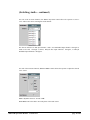
(Switching Audio – continued)
For each of the 20 audio channels, the Source drop-down control allows the operator to select a
―safe‖ audio source when switching that audio channel.
The choices include Aux AES input channels 1 and 2, Aux Embedded input channels 1 through 16,
Audio Test Tones 1 through 4, Silence, Delayed AES input channels 1 through 4, or Delayed
Embedded input channels 1 through 16.
For each of the 20 audio channels, Gain and Phase controls allows the operator to adjust the selected
―safe‖ source.
Gain is adjustable between –40 and +20dB.
Invert Phase can be checked to invert the phase of the audio source.
5000-AVD Operations Manual – Version 2.0.0
page 24 of 48
(Switching Audio – continued)
It is possible to Reset All of the audio channel settings to default values through a single control,
instead of having to go through each control individually.
The Source selection under Reset All is used to quickly assign all 20 channels to the selected source.
Delay 1:1 – This will assign all Delayed input channels to their corresponding switched output channels.
Delay AES Ch1 to switched Output AES Ch1,
Delay AES Ch2 to switched Output AES Ch2…
……..
Delay Emb Ch15 to switched Output Emb Ch15,
Delay Emb Ch16 to switched Output Emb Ch16.
Aux 1:1 – This will assign all Aux input channels to their corresponding switched output channels.
Aux AES Ch1 to switched Output AES Ch1,
Aux AES Ch2 to switched Output AES Ch2…
……..
Aux Emb Ch15 to switched Output Emb Ch15,
Aux Emb Ch16 to switched Output Emb Ch16.
Silence – This will assign all channels to silence.
Tone 1 – This will assign all channels to Tone 1.
Tone 2 – This will assign all channels to Tone 2.
Tone 3 – This will assign all channels to Tone 3.
Tone 4 – This will assign all channels to Tone 4.
The Switch Select control under Reset All is used to quickly assign a switch to all 20 channels.
The Gain Reset button under Reset All is used to quickly reset all 20 channels to 0.0 dB Gain.
The Phase Reset button under Reset All is used to uncheck all 20 channels’ Invert Phase settings.
5000-AVD Operations Manual – Version 2.0.0
page 25 of 48
Outputs Menu
The 5000-AVD has one SDI output (video plus 16 embedded audio channels) and 2 AES outputs (4 audio channels).
Output Video Selection
The top section of the Outputs menu contains the control for video selection.
The Output Select drop-down menu allows the user to select either the Delayed Video input or the
Aux Video input channel. Other choices include Black Video, the Test Signal, or one of 4 stored
Still Images in either Full Frame or Field modes (see Stills & Test Signals menus for more
information).
Keep in mind that if a Censor Switch is activated, then the Output Video may change depending on
the Switch settings.
5000-AVD Operations Manual – Version 2.0.0
page 26 of 48
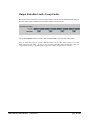
Output Embedded Audio Group Enable
The next section of the Outputs menu contains controls for each embedded audio group on the video
output (these controls are also available under the Delay & System menu).
Use the Group Enable buttons to enable (ON) or disable (OFF) each of the four audio groups.
Note: the 5000-AVD strips all ancillary embedded audio from the video input(s) and processes this
audio separately from video. In order to pass incoming embedded audio through the system, the
stripped audio must be re-embedded and the appropriate audio group(s) must be enabled.
Output Audio Channel Page Selection
The Output Audio Channels are organized in groups of 4, including Embedded Audio channels 1-4
(Group 1), Embedded Audio channels 5-8 (Group 2), Embedded Audio channels 9-12 (Group 3),
Embedded Audio channels 13-16 (Group 4), and AES audio channels 1-4 (AES). Each of these
groupings may be accessed through the thumb-tabs at the bottom of the menu window:
Output Audio Selection (Mapping)
For each of the 20 possible audio output channels, the Source drop-down controls allows the user to
select the audio Source which is to be output on each channel.
The choices include Aux AES input channels 1 and 2, Aux Embedded input channels 1 through 16,
Audio Test Tones 1 through 4, Silence, Delayed AES input channels 1 through 4, or Delayed
Embedded input channels 1 through 16.
5000-AVD Operations Manual – Version 2.0.0
page 27 of 48
(Output Audio Selection – continued)
Full Audio Mapping is possible with the Source control. Any source may be selected for any output
channel, including one source feeding multiple output channels.
Simultaneous Embedding and De-embedding is also realized with the Source control, since AES
inputs may be selected for Embedded outputs while Embedded inputs are selected for AES outputs.
If the user wants the Delayed AES Ch 1 input to be output on Embedded Ch 5, for example, then it is
possible through this control.
Keep in mind that if a Censor Switch is activated, then the Output Audio may change depending on
the Switch settings.
Output Audio Channel Controls
For each of the 20 output audio channels, Gain and Phase controls allow the operator to adjust the
selected source.
Gain is adjustable between –40 and +20dB.
Invert Phase can be checked to invert the phase of the audio source.
5000-AVD Operations Manual – Version 2.0.0
page 28 of 48
Output Audio Channel Resets
It is possible to Reset All of the audio channel settings to default values through a single control,
instead of having to go through each control individually.
The Source selection under Reset All is used to quickly assign all 20 channels to the selected source.
Delay 1:1 – This will assign all Delayed input channels to their corresponding output channels.
Delay AES Ch1 to Output AES Ch1,
Delay AES Ch2 to Output AES Ch2…
……..
Delay Emb Ch15 to Output Emb Ch15,
Delay Emb Ch16 to Output Emb Ch16.
Aux 1:1 – This will assign all Aux input channels to their corresponding output channels.
Aux AES Ch1 to Output AES Ch1,
Aux AES Ch2 to Output AES Ch2…
……..
Aux Emb Ch15 to Output Emb Ch15,
Aux Emb Ch16 to Output Emb Ch16.
Silence – This will assign all channels to silence.
Tone 1 – This will assign all channels to Tone 1.
Tone 2 – This will assign all channels to Tone 2.
Tone 3 – This will assign all channels to Tone 3.
Tone 4 – This will assign all channels to Tone 4.
The Gain Reset button under Reset All is used to quickly reset all 20 channels to 0.0 dB Gain.
The Phase Reset button under Reset All is used to uncheck all 20 channels’ Invert Phase settings.
5000-AVD Operations Manual – Version 2.0.0
page 29 of 48
Stills Menu
The Stills menu provides all controls for managing still images.
(Output Video Selection)
The Video Output Select control (from the Output menu) is duplicated at the top of the Stills Menu.
This makes it convenient to select the Still images for viewing as they are being captured or loaded.
5000-AVD Operations Manual – Version 2.0.0
page 30 of 48
Freeze AUX Input
The AUX video input may be frozen by clicking on the Freeze Image button (FREEZE).
Live video may be restored by clicking on the button again (NORMAL).
The Freeze Mode setting allows the frozen image to be displayed as a single field or a full frame.
Still Images
The 5000-AVD has four still image buffers. Each buffer may be selected for viewing with the Output
Select control, or used as a ―safe‖ source when switching away from objectionable material.
Each buffer may contain captured images from video, or images loaded from the SD/MMC card.
Images in each buffer may be saved to the SD/MMC card for future use.
Note: A MMC, SD or SDHC card must be installed on the 5000-AVD card to save and load still images.
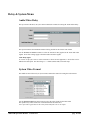
Loading Still Images
The Source drop-down control is used to select the image that will be loaded into the buffer. The first
two selections are always Delay and Aux, followed by a list of any still image files stored in the
SD/MMC card.
Selecting Delay allows an image to be captured from the Delayed
video input.
Selecting Aux allows an image to be captured from the Aux video
input.
Selecting a filename allows a still image to be loaded from the
SD/MMC card.
5000-AVD Operations Manual – Version 2.0.0
page 31 of 48
(Loading Still Images – continued)
The Capture/Load button is used to transfer the image into the buffer.
Capturing an Image from the Video Input
Use the Source control to select the Delayed (Delay) or Aux (Aux) video input.
Click on the Capture/Load button to instantly capture the current frame of video.
The Status bar will display 100% when the video frame has been captured.
Loading a Still Image from the SD/MMC card
Use the Source control to select the filename of a still image.
Click on the Capture/Load button to begin loading the selected still image file.
The Status bar shows the progress of the still image file loading, and will display
100% when the image file is completely loaded.
Note: Loading times are typically 1-5 seconds depending on
the format and the SD/MMC card that is used.
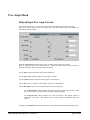
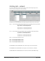
Saving Still Images to the SD/MMC card
The contents of the still image buffer(s) may be saved to the SD/MMC card using the Save Still
button. To enable the Save Still button, a valid filename, date, and time must be entered.
A filename must be entered in the (enter name) box. The name can be typed into the box, or the
drop-down control can provide a default name. A valid filename must be a unique name between
1 and 16 characters long, and may contain upper and lower case letters, spaces, and some special
characters: $ % „ + - = _ , ; @ ~ ` ! ( ) { } [ ] ^ # & .
The Save as… status box provides confirmation that a valid filename has been entered, or indicates
possible problems that prevent the still image from being saved.
< select name >
< already exists >
< illegal name >
5000-AVD Operations Manual – Version 2.0.0
A name must be selected or typed into the (enter name) box
followed by the Enter key.
The filename entered already exists. Change to unique name.
An illegal character has been used in the name.
page 32 of 48
(Saving Still Images – continued)
< no memory card >
< mem card full >
< WR protected >
< card too small >
< mem card error >
The SD/MMC card is not detected. Install a SD/MMC card.
The SD/MMC card is out of available memory space. Delete stills
to free up memory, or replace the SD/MMC card.
The SD/MMC card is write protected. Slide the ―LOCK‖ tab on the
SD/MMC card toward the top to enable writing.
The SD/MMC card has a FAT12 file structure, and is too small for
still image files. Use only FAT16 and FAT32 formatted SD/MMC
cards (typically > 64MB).
An error has occurred with the SD/MMC card. Try resetting the
SD/MMC card (see below) or replace the SD/MMC card.
The File Date and File Time controls are used for the creation date and time of the saved image
file. The default values come from a real time clock, and should maintain the correct date and time
as long as power is applied to the 5000-AVD.
To edit the File Date, place the cursor in the control box using the mouse. Delete the
current value, type in a new value, and press Enter.
To be accepted, the date must be in the exact form: ―YYYY-MM-DD‖
where YYYY is the Year (>2000), MM is the month, and DD is the day.
For example, July 4th 2010 is entered as “2010-07-04”
To edit the File Time, place the cursor in the control box using the mouse. Delete the
current value, type in a new value, and press Enter.
To be accepted, the time must be in the exact form: ―HH:MM XM‖
where HH is the Hour (1-12), MM is the minute, and XM is AM or PM.
For example, 1:30 pm is entered as “01:30 PM”
Click on the Save button to begin saving the selected still image to the SD/MMC card.
The Status bar shows the progress of the still image file being saved, and will
display 100% when the image file is completely saved.
Note: Loading times are typically 1-10 seconds depending on
the format and the SD/MMC card that is used.
5000-AVD Operations Manual – Version 2.0.0
page 33 of 48
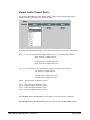
Deleting Still Images from the SD/MMC card
Unwanted Still Image files may be deleted from the SD/MMC card to free up memory for new stills.
To enable the Delete button, use the drop-down control to select a filename to be deleted.
Once a filename has been selected, click on the Delete button.
A dialog box will appear confirming if the file is to be deleted.
Click on Yes to delete the selected file.
Resetting the SD/MMC Card
In the unlikely event that the SD/MMC card becomes unresponsive, clicking on the Memory Card
Reset button should re-initialize the memory card.
If the SD/MMC card still fails to be detected or function correctly, the memory card may have to be
ejected and re-installed on the 5000-AVD card to regain proper operation.
5000-AVD Operations Manual – Version 2.0.0
page 34 of 48
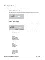
Test Signals Menu
The Test Signals menu provides controls for setting the video and audio test signals.
(Video Output Selection)
The Video Output Select control (from the Output menu) is duplicated at the top of the Test Signals
Menu. This makes it convenient to view the selected video test signals.
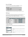
Video Test Patterns
Use the Video Test Patterns drop-down control to choose which test pattern will be displayed
when Test Signal is selected as the video output or is selected as a safe source for the censor switch.
Use the radio buttons to choose if the test pattern is to be displayed as Full Color, or Monochrome.
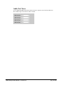
List of Video Patterns:
75% Color Bars
100% Color Bars
Bars Reversed
Tartan Bars
SMPTE Color Bars
RP219 (HD formats)
Composite (SD formats)
Alignment Chart
Multipulse
Multiburst
Horz Sweep
10 Step
100% Ramp
5% Shallow Ramp
Digital Ramp
75% Red Field
75% Green Field
75% Blue Field
50% Gray Field
F1-White/F2-Black
F1-Blue/F2-Yellow
SMPTE Checkfield
Digital Test
5000-AVD Operations Manual – Version 2.0.0
page 35 of 48
Audio Test Tones
Use the Audio Test Tones drop-down controls to choose a frequency for each of the audio tones.
The available range for each tone is 16 Hz to 20 kHz.
5000-AVD Operations Manual – Version 2.0.0
page 36 of 48
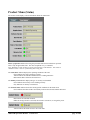
Product Menu (Status)
The Product menu displays various information about the 5000-AVD.
Hours of Operation indicates how long this particular 5000-AVD card has been powered.
This is only an approximate time. The value is updated every 3.75 minutes.
Note: Brand new cards will have a typical value between 72 and 80 hours. This is due to
standard 72 hour “burn-in” followed by final testing time.
The Card Status indicator displays the operating condition of the card.
Green indicates the card is operating correctly.
Yellow indicates an unusual condition such as ―Loading Firmware‖.
Red indicates that a failure has been detected.
The Memory Card indicator displays the type of memory card installed.
Green indicates the memory card is working correctly.
Gray indicates no memory card detected.
The Genlock Status indicator shows the current genlock condition for the 5000-AVD.
Green indicates the 5000-AVD is successfully locked to the selected Genlock Reference.
Red indicates an unlocked condition.
Either the wrong reference is selected, the reference is incorrect, or no signal is preset.
Yellow indicates the 5000-AVD is in Free-run mode.
5000-AVD Operations Manual – Version 2.0.0
page 37 of 48
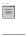
Rear Module Menu
This menu displays the signal connections for the 5000-AVD at the Rear panel module.
5000-AVD Operations Manual – Version 2.0.0
page 38 of 48
Updating the Firmware
Cal Media cards can be quickly and easily updated through Dashboard*, or using a MMC or SD memory card
(*Firmware can only be loaded with Dashboard™ on cards having firmware version 2.0 or greater already
installed).
Note:
The 5000-AVD should not be used on-air during the firmware installation process. The card will
stop communicating with Dashboard™ and will need to re-boot upon completion.
Obtaining New Firmware
The current version of firmware can be obtained from California Media Engineering (www.calmedia.com).
Preparing Firmware Files
The firmware will be provided as a .zip file. Before it can be used, the file must be unzipped.
Be certain that no errors occur during the unzip process.
Once unzipped, the firmware update should be a folder which contains several files.
Be sure and open the Read Me.txt file for any additional instructions.
To update the 5000-AVD using Dashboard™, copy or move the folder to a location accessible from Dashboard™.
To update the 5000-AVD using a MMC or SD memory card, copy the entire folder to a MMC or SD memory
card’s root directory.
Note: The 5000-AVD can only recognize one folder with a “.cme” extension.
If the memory card already has a “.cme” folder from an earlier version or
another product, then that folder must be moved from the root directory or
renamed or deleted. Do not combine files from other versions into the same
“.cme” folder, as the 5000-AVD will only read the first “.osx” file it finds.
5000-AVD Operations Manual – Version 2.0.0
page 39 of 48
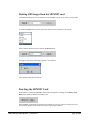
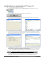
Installing Firmware using Dashboard™ Version 3.0
Note:
This process typically takes about 90 seconds.
1.
Launch the Dashboard™ application and open the 5000-A/V Delay card listed in the Basic Tree View.
2.
Click on the Upload button at the bottom of the Dashboard™ control screen.
3.
The Upload Software Wizard will open. Click Browse and navigate to the location of the firmware file
folder. Select the ―.bin‖ file and click Open.
4.
The Upload Software Wizard will now display the selected firmware file and its description. Click Next.
The 5000-AVD card should be selected to receive this file. If other 5000-AVD cards are listed, check these
cards too if they are to receive this firmware update.
5.
Click Finish to begin installing the new firmware. When the installation is complete Click OK. The Upload
Wizard will close and the 5000-AVD will automatically reboot with the new firmware. Verify that the new
version numbers are displayed on the Dashboard™ control Product menu.
Note: Some updates may require additional time for the initial reboot cycle (approx. 15 seconds).
WARNING! Do not cancel the upload or cycle power once the firmware begins copying
until the firmware is completely loaded and the card has rebooted.
If the firmware installation process is interrupted then the 5000-AVD card may not be able to reboot.
If Dashboard™ then fails to open the card, the firmware must be reinstalled using a memory card.
5000-AVD Operations Manual – Version 2.0.0
page 40 of 48
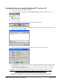
Installing Firmware using Dashboard™ Version 2.0
Note:
This process typically takes about 90 seconds.
1.
Launch the Dashboard™ application and open the 5000-A/V Delay card listed in the Basic Tree View.
2.
Click on the Upload button at the bottom of the Dashboard™ control screen.
3.
The Open dialog window will appear. Click Browse and navigate to the location of the firmware file folder.
Select the ―.bin‖ file and click Open.
4.
A confirmation window should now display the selected firmware file and its description.
5.
Click Continue to begin installing the new firmware. When the installation is complete the 5000-AVD
will automatically reboot with the new firmware. Verify that the new version numbers are displayed on
the Dashboard™ control Product menu.
Note: Some updates may require additional time for the initial reboot cycle (approx. 15 seconds).
WARNING! Do not cancel the upload or cycle power once the firmware begins copying
until the firmware is completely loaded and the card has rebooted.
If the firmware installation process is interrupted then the 5000-AVD card may not be able to reboot.
If Dashboard™ then fails to open the card, the firmware must be reinstalled using a memory card.
5000-AVD Operations Manual – Version 2.0.0
page 41 of 48
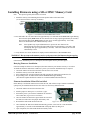
Installing Firmware using a SD or MMC Memory Card
Note:
1.
This process typically takes about 30 seconds.
Install the memory card containing the firmware update folder on the 5000-AVD
(see section Installation and Setup for details).
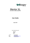
Figure 4-1. FLASH button and POWER LED location.
2. Press and hold in the ―FLASH‖ button for approximately 2 seconds until the POWER LED begins flashing.
The LED will rapidly flash red as the new firmware file is being copied (approximately 20 seconds).
The LED will then rapidly flash green as the new file is verified (approximately 10 seconds).
Once it has finished, the card will automatically re-boot.
Note:
Some updates may require additional time to process the new firmware file.
During this time the LED will again rapidly flash red (approximately 10 seconds), and
then rapidly flash green (approximately 5 seconds). Once it has finished, the card will
automatically re-boot.
3. Verify that the new version numbers are displayed on the Dashboard™ control Product menu.
WARNING! Do not remove the memory card or cycle power once the firmware begins copying
until the firmware is completely loaded and the card has rebooted.
If the firmware installation process is interrupted, then the update must be performed again.
Retrying Firmware Installation
If the first attempt has failed or was interrupted, the 5000-AVD may not function correctly or even boot.
To install the firmware under these conditions, a power-cycle firmware installation may be required.
1.
2.
3.
4.
Unseat the 5000-AVD card from the frame slot and wait a few seconds.
Install the memory card on the 5000-AVD.
Press and hold in the ―FLASH‖ button while fully inserting the 5000-AVD card into the slot.
Keep holding in the ―FLASH‖ button until the POWER LED begins flashing.
(The firmware update should now continue as a normal installation described above).
Firmware Installation if Boot File has failed
In the unlikely event that the 5000-AVD card will not boot, and will not accept a firmware installation,
a jumper may be installed which will force the card to use the factory default boot file.
1.
Unseat the 5000-AVD card from the frame slot.
2.
Install a jumper on J905 (pins 1-2) as shown (right).
3.
Perform the power-cycle firmware installation as described
above under Retrying Firmware Installation.
4.
Once the 5000-AVD has booted, again unseat the card from
the frame slot and remove the jumper and memory card.
5.
Re-install the 5000-AVD into the frame slot.
6.
Once installed, the 5000-AVD should automatically generate a new boot file. This should take
approximately 15 seconds as the POWER LED will rapidly flash red, then green.
7.
Upon completion, the 5000-AVD should successfully reboot.
5000-AVD Operations Manual – Version 2.0.0
Figure 4-2 Boot-Loader jumper location
page 42 of 48
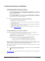
Troubleshooting Firmware Installation
Troubleshooting Dashboard™ Firmware Installation
Use the following information if the firmware upload process has failed:
• If the ―Selected file does not exist‖ or ―Selected file is not a valid upload file‖ error conditions are
displayed in the Upload Failed dialog box, select OK from the dialog box and re-start the upload
process and select the correct file.
• If a ―No response from device‖ condition is encountered, the upload failed while in progress due to
loss of power or communications. Verify that the card is powered up and there is communication
with the openGear™ frame. Restart the upload process.
In the unlikely event the 5000-AVD card becomes unresponsive, try the following:
1.
Unseat the 5000-AVD card from the frame slot and wait a few seconds.
2.
Reinstall the 5000-AVD card into the frame slot.
3.
If Dashboard™ is able to open the control panel for the 5000-AVD, repeat the installation
process using Dashboard™.
4.
If Dashboard™ is not able to open the control panel for the 5000-AVD, perform the installation
using a SD or MMC memory card (see previous section).
5.
If the 5000-AVD still does not properly operate after trying all suggestions, contact customer
support at [email protected].
Troubleshooting Memory Card Firmware Installation
If the LED does not begin to rapidly flash red when the FLASH button is pressed, check the following:
1. The FLASH button is not being pressed continuously for 2 seconds.
2. Possible bad memory card. Check if the memory card is indentified on the Dashboard™ control
Product menu. Try a different memory card.
3. Incorrect Firmware. Check that the Firmware files are meant for the 5000-AVD.
4. Incorrect Firmware files or folder. See Preparing Firmware Files section above.
A single “.cme” folder must be located in the root directory of the memory card.
A single file with a “.osx” extension must be located within the “.cme” folder.
If the POWER LED immediately changes from a rapidly flashing red (10 flashes a second) to a slower
flashing red (2 flashes a second) and continues flashing for more than a minute, then the firmware file (―.osx‖)
is incorrect or damaged. Check the files. Try again with a different memory card.
If the card has not re-booted after several minutes, then the firmware update has probably failed. Try again
with a different memory card.
Note:
It is safe to remove the memory card and/or power cycle the 5000-AVD as long as the POWER LED
is not rapidly flashing red (10 flashes a second).
If the 5000-AVD still does not properly operate after trying all suggestions, contact customer support at
[email protected] .
5000-AVD Operations Manual – Version 2.0.0
page 43 of 48
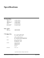
Specifications
Maximum Delay
1080i-60/59.94
1080i-50
1080PsF-24/23.98
720p-60/59.94
720p-50
SD 483i (NTSC)
SD 576i (PAL)
6 seconds 10 frames
7 seconds 15 frames
7 seconds 22 frames
7 seconds 8 frames
8 seconds 28 frames
30 seconds 28 frames
31 seconds 5 frames
Delay Adjust
Video
Audio offset
1 frame increments
0.25ms increments
Video Processing
Signal:
HD - 1.485Gb/s (SMPTE 292M)
SD - 270Mb/s (SMPTE 259M)
Inputs:
2 BNCs, 75ohm, 800 mVpp
HD - Auto EQ to 100 meters (Belden 8281)
SD - Auto EQ to 280 meters (Belden 8281)
Output:
BNC, 75ohm, 800 mVpp
HD Timing Jitter < 0.3UI
SD Timing Jitter < 0.2UI
Formats:
1080i-60/59.94/50
1080PsF-24/23.98
720p-60/59.94/50
483i-59.94
576i-50
Resolution:
10 bit, 4:2:2
Specifications subject to change without notice.
5000-AVD Operations Manual – Version 2.0.0
page 44 of 48
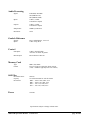
Audio Processing
Signal:
Embedded, AES/EBU
SD (SMPTE 272C)
HD (SMPTE 299M)
Inputs:
2 BNCs, 75ohm
Transformer coupled
Outputs:
2 BNCs, 75ohm
Transformer coupled
Sample Rate:
48KHz-synchronous
Resolution:
24 bit
Genlock Reference
Signals:
Inputs:
Bi-Lev (Black Burst) , Tri-Level
2 BNC loops, Hi-Z
Control
GPI Inputs:
2 BNCs, internal pullup
Activates on closure to ground
Remote Input:
RJ-45 Ethernet connector
Memory Card
Type:
Format:
MMC, SD, SDHC
FAT16 or FAT32 required for STILL storage
(cards > 64MB are typically FAT16 or FAT32)
Still Files
File Folder Name:
Capacity:
File Format:
Power
STILLS
253 stills maximum for each file format
.HD2 = 1920 x 1080, 10bit, 4:2:2
.HD1 = 1280 x 720, 10bit, 4:2:2
.SD2 = 720 x 576, 10bit, 4:2:2
.SD1 = 720 x 487, 10bit, 4:2:2
10 Watts
Specifications subject to change without notice.
5000-AVD Operations Manual – Version 2.0.0
page 45 of 48
5 YEAR LIMITED
WARRANTY
California Media Engineering Inc. warrants that this product (5000-AVD openGear™ card) is free from defects in
material or workmanship for a period of five (5) years from the date of original purchase. In the event this product
becomes defective through normal usage, California Media Engineering Inc. agrees to repair or at it’s option replace
the defective product without charge.
This warranty does not cover the DFR-8310/8320/8321 Frame, Network card or PS8300 Power supply(s).
This warranty is limited to the original end-purchaser and is not assignable or transferable. This warranty does not
apply to damage caused by negligence, accidents, or an act of God. Only a California Media Engineering Inc. factory
representative is authorized to repair this product. Any unauthorized attempt to repair this product will immediately
void the warranty. Any unauthorized alterations or modifications to this product will immediately void the warranty.
This product is designed specifically for standard openGear™ chassis’ and any attempt to operate this product outside
of an openGear™ chassis will immediately void the warranty.
California Media Engineering Inc. shall not be responsible for incidental or consequential damages, nor damage due to
misuse or the use of any unauthorized attachment or modification, nor damage by the use of an unspecified electrical
circuit. In no event shall California Media Engineering Inc. be responsible or liable for any damages arising from the
use of this product, whether such damages be direct, indirect, special, incidental, consequential, or otherwise.
California Media Engineering Inc. shall not be liable for any loss of use, revenue or profit.
Any software provided for use with this product is provided ―AS IS.‖ California Media Engineering Inc. shall not be
responsible or liable for any damages arising from the use of said software, whether such damages be direct, indirect,
special, incidental, consequential, or otherwise.
This warranty gives you specific legal rights, and you may also have other rights which vary from state to state. Any
implied warranty is limited in duration to five years provided in this, the only, expressed warranty.
5000-AVD Operations Manual – Version 2.0.0
page 46 of 48
Repair Policy
Should any problem arise with your 5000-AVD openGear™ card, please contact Cal Media’s Technical Support
Department at [email protected] or use the contact information on the back cover of this manual.
If required, a Return Material Authorization number (RMA) will be issued to you, as well as specific shipping
instructions. Do not return any product before obtaining a RMA number. Any shipping costs incurred are the
customer’s responsibility. If available, a temporary replacement card may be provided at a nominal charge.
Cal Media’s Technical Support Department will continue to provide advice on any product manufactured by Cal
Media, beyond the warranty period without charge, for the life of the product.
5000-AVD Operations Manual – Version 2.0.0
page 47 of 48
California Media Engineering Inc.
Voice: (805) 931-0857
Fax:
(805) 299-4581
[email protected]
[email protected]