1
TeleEye
Reception Software WX-30
User Manual
Notice :
Signal Communications Limited reserves the right to make improvements to the
product described in this manual at any time and without notice.
This manual is copyrighted. All rights are reserved. This manual should not be
copied, reproduced or translated in whole or part without prior consent from Signal
Communications Limited.
TeleEye is a trademark of S ignal Communications Limited and is registered in
China, European Communities, Hong Kong, US and other countries.
All other trademarks are the property of their respective owners.
Copyright (c) 2007 Signal Communications Limited (A member of TeleEye Group).
All rights reserved.
Version 3.32.10
Limits of Liability and Disclaimer of Warranty
Signal Communications Limited has taken care in preparation of this manual, but
makes no expressed or implied warranty of any kind and assume no responsibility for
errors or omissions. No liability is assumed for incidental or consequential damages in
connection with or arising out of the use of the information or accessories contained
herein.
Features and specifications are subject to change without prior notice.
Table of Contents
SECTION 1
INTRODUCTION
1
1.1
1.2
Introduction
System Requirement
1
2
1.3
Manual Convention
3
SECTION 2
GETT ING STARTED WIT H
2.1
Ins talling TeleEye Reception Software WX-30
2.2
2.3
Multi - Language Setting
Registering TeleEye RX Video Transm itter
SECTION 3
CONNECT / DISCONNECT TeleEye RX TRANSM ITTER
4
4
10
11
14
3.1
Connect TeleEye RX
3.2
3.3
Auto Redial
Disc onnect TeleEye RX
3.4
Auto Disc onnec t
21
22
3.5
Connection Log
24
SECTION 4
TRANSMITTER GENERAL SETUP
4.1
4.2
Transmitter In formation
Change Password(Basic security mode), Upgrade Version,
14
20
27
29
30
Registration Checking & User account management (Advanced
security mode)
4.3
4.4
Video Settings
Connection
4.4.1
4.4.2
Network Settings
Modem Settings
39
41
42
45
4.4.3 3G USB Modem Setting
4.5 RXSE
47
48
4.6
4.7
Date / Time
HDD Management
51
54
4.8
4.9
Restore Factory Setting
Restart Transmitter
56
57
4.10 Time Sync Tes t
58
4.11 s ureLINK Setup
60
4.12 Backup Setting Import / E xport
4.13 External Keyboard
62
64
SECTION 5
REMOTE LIVE MONITORING
5.1
Sc reen Mode & Cam era
65
65
5.2
5.3
Full Sc reen & Keep As pect Ratio
Text Display & Text Colour
72
74
5.4 Live Quality Setting
SECTION 6
RECORDING
75
6.1
Recording Setup
78
78
6.2
6.3
Manual Rec ording
Footage Extraction
81
83
6.4 Audio Recording
6.5 PC rec ording Setup
SECTION 7
PLAYBACK
86
87
7.1
Start Playback
88
88
7.2
7.3
Playback Control
Multiple s earc h
93
94
SECTION 8
EVENT HANDLING
8.1
Event
96
96
8.1.1
8.1.2
Arm / Disarm
Sec urity Switch
98
101
8.1.3
8.1.4
Alarm
Motion
104
115
8.1.5
8.1.6
Video Loss
Sys tem Tamper
121
123
8.1.7 Power Failure
8.2 Ac tion
125
127
8.2.1
8.2.2
Live Camera
Rec ording
129
131
8.2.3
Switch
135
8.3
8.2.4
8.2.5
Dial Bac k
Pan Tilt Zoom (PTZ)
139
143
8.2.6
8.2.7
Event LED
Buzzer
145
147
8.2.8
8.2.9
Spot Alarm
Email setup
148
149
8.2.10 SMS
8.2.11 Dialbac k Test
151
152
Event Indication
8.3.1 Event Panel
154
155
8.3.2
8.3.3
Event Status
Event Log
158
160
8.3.4
8.3.5
Siren
Clear Event
164
165
SECTION 9
PAN TILT ZOOM
167
PTZ Settings
PTZ Contro l
167
172
9.3 PTZ Ad vance Settings
SECTION 10
SWIT CHES
175
9.1
9.2
10.1 Switc hes Settings
181
181
10.2 Switc hes Control
184
SECTION 11
LOG & PICTURE BACKUP
186
11.1 Open & Save Pic ture
11.2 Preview
186
190
11.3 Printer Setup & Printing
193
SECTION 12
CONNECTION SCHEDULER
194
12.1 New Sc hedule
12.2 Delete Schedule and Change Properties
SECTION 13
AUDIO CONTROL
198
201
13.1 Pre-recorded voice file s etting
203
203
13.2 Audio control
206
SECTION 14
TROUBLE SHOOT ING
207
SECTION 15
APPENDIX
208
15.1 sureLINK Technology
15.2 TeleEye RX with Tamper Circuit and External Resistor
15.3 Sec urity Mode
208
213
216
TeleEye Reception Software WX-30 Use r Manual
PAGE 1
Section 1
Introduction
1.1
Introduction
Thanks for using TeleEye Re ce ption Software WX-30. This software is a Windows
2000/XP/Vista/7 application software. It is designed to implement for remote monitoring and
controlling TeleEye RX video transmitter. The compressed data are decoded and displayed
through the PC monitor. User can select the desirable video source, resolution and quality from
the graphical user interface.
Introduction
TeleEye Reception Software WX-30 Use r Manual
1.2
PAGE 2
System Requirement
Computer :
Personal C omputer
Processor :
Intel Pentium IV 2G or above
Memory :
256MB RAM or above
Hard D isk :
Minimum 41MB hard disk space required
Drive :
CD-ROM
Display :
800x600, high-colour
Sound :
Sound card is required
Ethernet Card :
10/100Mbps or above
Port :
Serial Port
Operating S ystem : Microsoft Windows 2000 / XP
Windows XP/2000 us ers must hav e "Comput er Administrator" permissions and Windows Service Pack 2 or later.
System Requirement
TeleEye Reception Software WX-30 Use r Manual
1.3
Manual Convention
{
}
: Represent Windows panel name
[
]
: Represent Windows icon or button name
: Special note for user
: Refers to other section
: Next step
**
: Special Remark
Fig 1.1 .1 a
: All figure number is located on the bottom under the figure.
: Key to press or special emphasis place on a figure.
Manual Convention
PAGE 3
TeleEye Reception Software WX-30 Use r Manual
PAGE 4
Section 2
Getting Started W ith
Installing TeleEye Reception Software WX-30
2.1
TeleEye Reception Software WX-30 software CD installation procedure is easy to do.
Installation Pro ce dure :
Step 1 :
Ins ert the software CD int o the
CD-ROM. The CD can auto
run. {S etup} panel pop up.
Choos e
[Tele Eye
Re cepti on
S oftware – WX-30] option and
then click [O K] button.
Fig 2.1a
If the software CD cannot auto run, please choose the corresponding CD-ROM to run the
CD.
Step 2 :
Click [Next] button on the
{TeleEye WX-30 S etup} panel
Fig 2.1b
Installing TeleEye Reception Software WX-30
TeleEye Reception Software WX-30 Use r Manual
Step 3
PAGE 5
In
{Installing
Mi crosoft(R)
DirectX(R)} pop up window,
select [I acce pt the agreemen t]
and
click [Next] to inst all
DirectX
9.0c(April
2007
vers ion). Follow the instruction
to
complet e
DirectX
installation.
**D irectX inst allat ion must be
Fig 2.1c
completed before Step 4.
Step 4 :
Click
[Yes ]
software
to
accept
licens e
the
agreement,
otherw ise the s oftware cannot be
installed.
Fig 2.1d
Step 5 :
Fill
in
[Use r
[Compan y
Name ]
Name].
and
C lick
[Next] button to continue the
installation
Fig 2.1e
Installing TeleEye Reception Software WX-30
TeleEye Reception Software WX-30 Use r Manual
Step 6 :
PAGE 6
Choos e the dest ination folder to
store the software. Default path
is C:\Program File\Tele Eye\
WX-30.
[Browse]
anot her
User
button
path
to
may
click
to
s elect
store
the
software. After choos ing the
destination folder pat h, click
Fig 2.1f
[Next] to the next step.
Step 7 :
Choos e the type of s etup.
Choos ing
[Typi cal],
[Compact], [Custom] option
for
inst allation.
[Cus tom]
option allows us er to inst all
which p art of t he s oftware
manually. Other options will
install the software into PC
Fig 2.1g
automatically. [Typi cal ] option
is highly recomm ended. C lick
[Next] to continue.
Installing TeleEye Reception Software WX-30
TeleEye Reception Software WX-30 Use r Manual
Step 8 :
PAGE 7
Fill in [Program Folders] for
the folder nam e displayed on
the
[Start
Windows.
Up]
Default
menu
of
name
is
TeleEye .
Fig 2.1h
Step 9 :
{TeleEye WX-30 S etup} p anel
shows set up type, dest ination
folder and user information for
user to check w het her their
input options correct or not. If
there is no correction, click
[Next]] button to install the
software.
Fig 2.1i
Step 10 :
Inst allation is in p rogres s until
100%
Fig 2.1j
Installing TeleEye Reception Software WX-30
TeleEye Reception Software WX-30 Use r Manual
Step 11 :
PAGE 8
Inst allation is successful. It is
highly recomm ended user to
restart the PC before us ing the
software.
Click [Fi nish]
complete
the
to
inst allation
process.
Fig 2.1k
Step 12:
For Windows
(Vista)
[Start]
Vista, go to
->[All program]
->[Tele Eye]
Right click [Tele Eye WX-30]
and click [Properties ].
Fig 2.1l
Installing TeleEye Reception Software WX-30
TeleEye Reception Software WX-30 Use r Manual
PAGE 9
Step 13:
In
[Compati bility]
Option,
(Vista)
select [Ru n this program as an
administrator] and click [OK]
button.
Fi g 2.1m
Installing TeleEye Reception Software WX-30
TeleEye Reception Software WX-30 Use r Manual
2.2
PAGE 10
Multi – Language Setting
TeleEye RX transmitter supports Multi-language. The default setting of language is E nglish.
Language Setting Procedure :
St ep 1 : Click [Help] [Language] option on the {Main Panel}
Fi g 2.2a
St ep 2 :
{S elect Lan guage} p anel pop
up. Choose language in t he
com bo box button [Language ]
Fi g 2.3b
Registering TeleEye RX Video Transmitter
TeleEye Reception Software WX-30 Use r Manual
2.3
PAGE 11
Registering TeleEye RX Video Transmitter
TeleEye RX transmitter supports registration checking function in order to prevent illegal
access from other PC. By default, registration checking function is disabled, but it is hig hly
re co mme nded to do the transmitter registration after the installation of TeleEye Re ce ption
Software WX-30.
Transmitte r Registration Procedure :
St ep 1 : Click [Tran smitte r] [Registrati on] option on the {Main Panel}
Fi g 2.3a
Registering TeleEye RX Video Transmitter
TeleEye Reception Software WX-30 Use r Manual
PAGE 12
St ep 2 :
{Regis tration} panel pop up
St ep 3 :
Fill
Fi g 2.3b
in
[S erial
[Re gistration
No.]
and
Code]
as
example s hown on Fig 2.2c.
Click [OK] button to register
the TeleEye RX transmitter.
Fig 2.3c
Registering TeleEye RX Video Transmitter
TeleEye Reception Software WX-30 Use r Manual
St ep 4 :
PAGE 13
[Re gistration
Complete d!]
mes sage pop up. Click [O K]
to complet e and exit the panel.
Fi g 2.2d
During the registration process, user needs to fill in the transmitter’s serial number and
reg istratio n co de which are included in the transmitter package.
Registering TeleEye RX Video Transmitter
TeleEye Reception Software WX-30 Use r Manual
PAGE 14
Section 3
Connect / Disconnect
TeleEye RX Transmitter
3.1
Connect TeleEye RX
After registering TeleE ye RX transmitter in TeleEye Reception Software WX-30, user
needs to setup the network configuration of the transmitter for the first time connecting to the
PC.
For TeleEye RX transmitter network configuration setup, please refer to TeleEye RX
User Guide section 3 : Basic Installation for Local and Remote Monitoring.
Location
This is a naming input which record TeleE ye RX transmitter location, so no special
effect take place for this input.
Conne ction Using
TeleEye RX transmitter supports multiple connection stream. The usage of different
connection stream option is
TCP/IP LAN
: Local area network
TCP/IP Broadband
: Internet broadband network
TCP/IP Narrowband
: PSTN / ISDN, GPRS, or other mobile networks
Mo dem Driver
: Modem connection with known modem driver
Direct to Com X
: Leased line for null modem connection
General Modem
: Modem connection with unknown modem driver
Pho ne / IP
Connect TeleEye RX
TeleEye Reception Software WX-30 Use r Manual
PAGE 15
For TCP /IP LAN, TCP /IP broadband and TCP/IP narrowband connection stream, IP of
the transmitter is necessary to input in this blank. F or modem connection, pho ne numbe r
of the transmitter is needed to input here.
Prope rties
Allow user to change the connection bit rate and TCP /IP port number.
Password
There are two security mode – Basic se curity mo de and adv anced security mo de.
(Advanced security mode is for RX 360 series ONLY)
The transmitter supports 2 types of account, administrator account and user account, for
basic se curity mo de . User needs to input the correct administrator passwo rd or use r
password in order to connect to the transmitter with different privilege.
Default administrator password is 0 00 000, default user passwo rd is 123456
For details of changing the password, please refer to P. 26 of Section 4.2 : C hange
P assword & Registration Checking.
The transmitter supports 20 definable users for advanced security mode, including 18
normal user accounts and 2 special defined user accounts.(‘ADMINISTRATOR’ and
‘DEFAULT LOCAL USER’)
Default lo cal administrato r passwo rd is 111111, default re mote administrato r
password is 0 00000.
For details of security mode, please refer to Section 15.3 on P. 209: Security mode.
Connect TeleEye RX
TeleEye Reception Software WX-30 Use r Manual
PAGE 16
Dialing Pre fix
For modem connection only. This is phone number prefix of the transmitter.
Pho ne Book
P hone book is used for recording the IP or phone number of TeleE ye RX transmitter at
different surveillance area. It stores the data items as above : location, IP / Phone No.,
password, etc.
New
: Add a new TeleEye RX transmitter phone book items
Delete
: Delete the selected TeleEye RX transmitter phone book items
Pro pe rties
: Change the selected TeleEye RX transmitter phone book item
Refe re nce Co de
This is a quick reference code for different phone book items.
Add Pho ne Book Procedure :
St ep 1 : Press [Connect]
icon t o pop up {Conne ct} panel as Fi g 3.1a
Fi g 3.1a
Connect TeleEye RX
TeleEye Reception Software WX-30 Use r Manual
St ep 2 :
PAGE 17
Click [New] button on Fi g
3.1a to pop up {Phone Book}
panel t o add a new it em.
Fig 3.1b
St ep 3 :
Fill in the information for
location, IP, p assword, etc.
Click [OK] button to complet e
adding new it em.
Fig 3.1c
Connect TeleEye RX
TeleEye Reception Software WX-30 Use r Manual
St ep 4 :
PAGE 18
A new it em has been added in
the phone book.
Fig 3.1d
Connect TeleEye RX
TeleEye Reception Software WX-30 Use r Manual
PAGE 19
Conne ction Pro cedure :
St ep 1 :
Choos e the s uit able phone
book item of TeleEye RX
transmitter as Fig 3.1e. Click
[Connect] butt on to connect
to the transmitt er.
Fig 3.1e
St ep 2 :
After clicking the [Conne ct]
button a few s econd later, it
changes t o the main panel.
Fig 3.1f
Connect TeleEye RX
TeleEye Reception Software WX-30 Use r Manual
3.2
PAGE 20
Auto Redial
If TeleEye Reception Software WX-30 loses connection to the TeleEye RX transmitter
abnormally, auto redial allows the software to reconnect to the transmitter automatically and
infinitely until successful connection established between the PC and the transmitter.
Auto redial will NOT function if user disconnects the transmitter manually or auto
disconnect function activated.
Auto Redial Setup Pro cedure :
St ep 1 : Click [Connection] [Au to Re dial] option on the m ain p anel in order to enable auto redial funct ion.
Fi g 3.2a
Auto Redial
TeleEye Reception Software WX-30 Use r Manual
3.3
PAGE 21
Disconnect Video Transmitter
If user needs to disconnect the transmitter, it is easy to do.
Disconnect Transmitte r Pro cedure :
St ep 1 :
On
the
main
p anel,
[Disconne ct]
Fig 3.3a
click
icon
to
disconnect t he transmitter.
St ep 2 :
{Disconne ct} p anel pop up. Click
[Yes]
button
to
close
t he
connection.
Fig 3.3b
St ep 3 :
If there is any event triggered
before with ou t cle ar, {Clear
Alarm} panel p op up. Us er needs
to input t he alarm p assword in
order to clear t he event first, and
then disconnect it. After inputting
Fig 3.3c
the password, click [OK] to
disconnect it.
Disconnect TeleEye RX
TeleEye Reception Software WX-30 Use r Manual
3.4
PAGE 22
Auto Disconnect
Auto disconnect allows user to schedule for disconnecting the transmitter.
None
Disable auto disconnect function
All Call
For all types of connection, disconnect the transmitter after the specific time
automatically. T he minimum auto disconnect time is 1 minute.
IDD Call
Only the IDD call with the input phone number prefix can auto disconnect the transmitter
after the specific time.
Auto Disco nnect Setup Procedure :
St ep 1 :
Click [Connection ] [Auto
Disconne ct] option on t he
main
p anel.
{Auto
Disconne ct} panel pop up.
Select the aut o dis connect type
[None ], [All Calls], [IDD
Fig 3.4a
Calls]
St ep 2 :
Suppos e
[IDD
Calls]
is
selected. Press [Up / Down]
Fig 3.4b
icon t o s elect [H ou r] and
[Minute]
to
disconnect t ime.
Auto Disconnect
choose
aut o
TeleEye Reception Software WX-30 Use r Manual
St ep 3 :
PAGE 23
Click [Add] button on {Auto
Disconne ct}
panel.
{Add
Prefix} p anel p op up and input
the prefix. Pres s [OK ] t o s ave
and exit the s etting.
Fig 3.4c
St ep 4 :
Press [OK] to save t he s etting
and exit the panel.
Fig 3.4d
Auto Disconnect
TeleEye Reception Software WX-30 Use r Manual
3.5
PAGE 24
Connection Log
Connection log shows TeleE ye Rece ption Software WX-30 connection record.
Procedure :
St ep 1 : Click [Connection] [Connection Log] option on the {Main Panel}
Fi g 3.5a
Connection Log
TeleEye Reception Software WX-30 Use r Manual
PAGE 25
St ep 2 : {Connection Log} p anel pop up.
Fi g 3.5b
St ep 3 :
User can select t he start dat e
of connect ion log disp lay.
Fig 3.5c
St ep 4 :
Fig 3.5d
User may clear the event
status by pressing [Clear]
button. P ress [Close] to clos e
the event status .
Connection Log
TeleEye Reception Software WX-30 Use r Manual
PAGE 26
Conne ction Log Column Description :
Start Date
It is the date for starting connection between the PC and the transmitter.
Start Time
It is the time for starting connection between the PC and the transmitter.
End Date
It is the date for disconnecting between the PC and the transmitter.
End Time
It is the time for disconnecting between the PC and the transmitter.
Refe re nce Co de
It is the reference code for the transmitter in the phone book.
Location
It is the location of the site in the phone book
Pho ne
It is the IP or phone number of the transmitter.
Status
It is the connection status between the transmitter and the PC.
Connected
: The transmitter and the P C have been connected
Line dropped
: Disconnection between the PC and transmitter by other netw ork
situation, NOT user manually disconnected.
Incorrect password : User input incorrect password to connect to the transmitter lead
to connection fail.
Connection Log
TeleEye Reception Software WX-30 Use r Manual
PAGE 27
Section 4
Transmitter General Setup
Transmitte r Ge ne ral Setup Procedure :
St ep 1 : Click [Tran smitte r S ettings]
icon on the {Mai n Panel}
Fi g 4a
St ep 2 :
{Admi nistrator
Password}
panel pop
Input
password
up.
and
the
click [O K]
button to enter {Transmi tter
S etup} panel.
Fi g 4b
The default administrator password is 0 00000
St ep 3 : {Transmitte r S etup} p anel p op up, so us er can do the trans mitter setting in t his panel.
Transmitter General Setup
TeleEye Reception Software WX-30 Use r Manual
PAGE 28
User can click [Re lo ad] button to reload the most update transmitter setting, if
The information on {Transmitter Setup} panel cannot fully display
Someone has changed the setting through the transmitter OSD menu or other PC
such that the information on {Transmitte r Se tup} panel is not updated.
User can click [Apply] button to save the current transmitter setting into TeleEye RX
transmitter. P ress [Close] button to exit the panel.
Transmitter General Setup
TeleEye Reception Software WX-30 Use r Manual
4.1
PAGE 29
Transmitter Information
Transmitter information shows the basic information of the TeleEye RX video transmitter.
Name
This shows the name of TeleEye RX video transmitter. User can change its name here.
Serial Numbe r
This shows the serial number of TeleEye RX video transmitter.
Model
This shows the model of TeleEye RX video transmitter.
Versio n
This shows the firmware version of TeleEye RX video transmitter.
Fi g 4.1a
Change Password, Registration Checking & User Account Management
TeleEye Reception Software WX-30 Use r Manual
4.2
PAGE 30
Change Password(Basic security mode), Upgrade
Version, Registration Checking & User account
management(Advanced security mode)
TeleEye RX transmitter provide high level of access security protection. It has administrator
and user account privilege to protect normal user to change the transmitter setup illegally.
Registration checking prevents the transmitter from illegal access by TeleEye Re ce ption
Software WX-30 of other P C.
Administrato r Password
It is the administrator account password. Some operations need to enter the administrator
password, such as transmitter setup, entering event log and recording. Default
administrator password is 000000 .
Use r Password
It is the user account password, so normal user can connect to the transmitter using this
password. Default user password is 123456 .
If user forget the administrator or user password (not default one), please contact us
by sending an email to : support@TeleE ye.com.
Administrator and user password are saved on each TeleE ye RX transmitter, not
the P C.
Reg istratio n Checking
If user has registered the transmitter, registration checking can be enabled. Registration
checking function is disabled at default.
For transmitter registration procedure, please refer to P.8 of Section 2.2 Registering
TeleEye RX Video Transmitter.
Change Password, Registration Checking & User Account Management
TeleEye Reception Software WX-30 Use r Manual
PAGE 31
Change Passwo rd Procedure :
St ep 1 :
On {Transmitter In formation}
panel, click [Change Password]
Fig 4.2a
button
for
password
administration
or
user
password
change
St ep 2 :
Enter the old password, new
password and confirm the new
password again. Click [O K] t o
save the new pas sword and exit
the panel. Press [Apply] button
on {Transmitter S etup} p anel t o
save
Fig 4.2b
the
s etting
to
the
transm itter.
Reg istratio n Checking Procedure :
St ep 1 :
Fig 4.2c
On {Transmitter In formation}
panel,
click
Checkin g]
[Registration
checkbox.
Pres s
[Apply] button on {Transmi tter
Setup} panel to s ave the s etting
to the transmitt er.
Change Password, Registration Checking & User Account Management
TeleEye Reception Software WX-30 Use r Manual
PAGE 32
Upg rade Versio n Procedure :
St ep 1 :
On {Transmitter In formation}
panel,click[Upgrade Firmware]
Fig 4.2d
St ep 2 :
A panel [Ch oose an RX file for
firmware u pgrade] will pop up.
Choos e t he rxp file and click
[Open].
Fig 4.2e
St ep 3:
A panel [Upgrade Fi rmware ]
will pop up and click [Start] t o
start upgrading.
Fig 4.2f
St ep 4:
A warning message will pop up,
click [Yes] to continue
Fig 4.2h
St ep 5:
Wait
until t he progress
bar
becam e full.
**Do not clos e t he panel until
up grading finis hed.
Fig 4.2i
Change Password, Registration Checking & User Account Management
TeleEye Reception Software WX-30 Use r Manual
PAGE 33
Adv anced Se curity Mo de Use r Account Manageme nt (Only for RX 360 series):
(i) S witch Security Mo de :
St ep 1 : Click [User se ttin g] option on {Transmi tter S etu p} p anel t o enter {Use r Accounts} Tab.
St ep 2: Click [Basi c se curity mode settings] / [Advanced se curity mode settings] checkbox.
Change Password, Registration Checking & User Account Management
TeleEye Reception Software WX-30 Use r Manual
PAGE 34
St ep 3. Inp ut required p assword checking information in {Pass word checking} panel.
For swit ching to basic s ecurity mode, ent er adm inistrator password.
For swit ching to advanced security mode, enter password and username of a us er w ho has “USER ACCOUNT "
group p erm iss ion.
St ep 4. Click
button to s ave the setting. The trans mitter will rest art autom at ically if password
checking is successful.
Change Password, Registration Checking & User Account Management
TeleEye Reception Software WX-30 Use r Manual
PAGE 35
(ii) Add use r for adv ance d security mode:
St ep 1 : In {User Accou nts} Tab, click [Add] button.
St ep2: In {User Accou nt Information } p age, ent er the user informat ion and click [OK] butt on.
(Note: 1. At least one user type must be s elected. 2. At least one cam era must be select ed)
St ep 3: Click
button t o s ave the s etting.
(iii) Edit user settings for advanced security mode:
St ep 1 : In {User Accou nts} Tab, s elect the t arget us er and click [Edit] button.
Change Password, Registration Checking & User Account Management
TeleEye Reception Software WX-30 Use r Manual
PAGE 36
St ep 2: In {User Account Information} page, edit the s ettings of the us er and click [O K] button
(F or changing pas sword, click [Ch ange] button and ent er the old password and new password.)
St ep 3: Click
button t o s ave the s etting.
Change Password, Registration Checking & User Account Management
TeleEye Reception Software WX-30 Use r Manual
PAGE 37
(iv) De le te user for adv ance d security mode:
St ep 1 : In {User Accou nts} Tab, s elect the t arget us er and click [Delete] button.
St ep 2: Click
button t o s ave the s etting.
(v ) Mo dify Po wer On De fault Right
St ep 1 : In {User Accou nts} Tab, click [Change settings of Powe r On Default Ri ght] button.
St ep 2 : In {Powe r On Default Ri ght} Page, change the settings and click [O K] button.
St ep 3: Click
button t o s ave the s etting.
Change Password, Registration Checking & User Account Management
TeleEye Reception Software WX-30 Use r Manual
4.3
PAGE 38
Video Settings
Video settings menu allow s user to do the camera related setting : video mode, PTZ driver,
camera installation and camera name.
Video Mode
It is video standard setting. Video mode supports NTSC and PAL option. All cameras
connected to the transmitter are necessary to have same video mode.
PTZ Drive r
The transmitter supports 3 types of PTZ driver : P elco D, TeleEye DM4 Series and
TeleEye DM Series. The 5 baud rate levels : 2400 bps, 4800bps, 9600bps, 14400 bps
and 19200bps.
Video Se tting s Setup Pro cedure :
St ep 1 : Click [Vi deo S ettings] option on {Transmitter S etup} p anel t o enter {Video S ettings} panel.
Video Settings
TeleEye Reception Software WX-30 Use r Manual
PAGE 39
Fi g 4.3a
St ep 2 :
Click the button to select
NTS C or PAL video mode
Fig 4.3b
St ep 3 :
Click [Installe d] checkbox t o
install t he camera and edit t he
Fig 4.3c
cam era name.
St ep 4 :
For
VGA
sett ings,
click
[Res oluti on] Combo Box and
[Fre quen cy] Com bo B ox t o
Fig 4.3d
select
value.
Video Settings
their
corresponding
TeleEye Reception Software WX-30 Use r Manual
4.4
PAGE 40
Connection
TeleEye RX transmitter supports different kind of connection device. The menu allow s user
to set TCP/IP and modem settings.
Conne ction Setup Procedure :
St ep 1 : Click [Connection] option on {Transmitter S etup} panel to enter {Conne cti on S ettings} panel.
Fi g 4.4a
Connection
TeleEye Reception Software WX-30 Use r Manual
PAGE 41
4.4.1 Network Settings
Network settings menu allows user to do TCP/IP connection stream configuration. If user setup
TeleEye RX transmitter for the 1st time, it is highly recommended to follow the setup steps in
the TeleEye RX User Guide first.
IP
The Internet protocol (IP) address of the transmitter set by user or given by user’s ISP.
Gateway
The Internet protocol (IP ) address of the router / network sw itch of user ’s network or
given by user’s ISP that is connected to the transmitter.
DNS
The Internet protocol (IP) address of the domain name server (DNS) of user ’s network or
given by user’s ISP that is connected to the transmitter.
sureLINK
sureLINK supports TeleE ye transmitter w ith dynamic IP. User can set sureLINK
update the transmitter IP every 15 minutes, 30 minutes, 45 minutes and 60 minutes. User
need to apply for a sureLINK account before using this function.
For the details of sureLINK, please refer to P.162 of Section 14.1 : sureLINK
Technology
Connection Settings
TeleEye Reception Software WX-30 Use r Manual
PAGE 42
Netwo rk Settings Procedure :
St ep 1 : Click [Conne cti on] [Network ] option on {Transmitte r S etup} p anel t o ent er {Network S ettings}
panel as shown on Fig 4.4.1a.
Fig 4.4.1a
St ep 2 :
Fill in the general network
setting items.
Fi g 4.4.1b
Connection Settings
TeleEye Reception Software WX-30 Use r Manual
St ep 3 :
PAGE 43
Click
[Using
s ure LINK
Address] checkbox t o enable
s ureLINK function. F ill in t he
sureLINK
with
the
recommended form at :
Fi g 4.4.1c
www.your_site.you r_compan y.Tele Eye.net
Select
sureLINK addres s
refresh rate.
St ep 4 :
Press
[Apply]
button
on
{Transmi tte r S etup} panel t o
Fi g 4.4.1d
save
the
setting
to
t he
transmitter.
If user change any connection settings, after pressing [Apply] button, the transmitter will
restart.
Connection Settings
TeleEye Reception Software WX-30 Use r Manual
PAGE 44
4.4.2 Modem Settings
Network settings menu allows user to do modem connection configuration. If user setup
TeleEye RX transmitter for the 1st time, it is highly recommended to follow the setup steps in
the TeleEye RX User Guide first.
Baud Rate
It is the baud rate of the modem connection. H igher baud rate can have higher connection
speed.
Ring Count
It is the ring count of the modem before connecting to the transmitter.
Extra Initializatio n Co mmand
It is used for inputting modem AT command for controlling the modem.
Connection Settings
TeleEye Reception Software WX-30 Use r Manual
PAGE 45
Modem Se ttings Pro cedure :
St ep 1 : Click [Connection] [Modem] option on {Transmitter S etup} panel to ent er {Modem S ettings} p anel
as shown on Fi g 4.4.2a., s elect modem interface in [Inte rface] C om bo Box.
Fig 4.4.2a
St ep 2 :
Choos e
[Baud
Rate]
and
[Rin g Coun t] s etting items .
Fi g 4.4.2b
St ep 3 :
Press
[Apply]
button
on
{Transmi tte r S etup} panel t o
Fi g 4.4.2c
save
the
transmitter.
Connection Settings
setting
to
t he
TeleEye Reception Software WX-30 Use r Manual
PAGE 46
4.4.3 3G USB Modem Setting :
For firmware s upporting 3G USB Modem, an additional option will appear as F ig 4.4.3a:
Fig 4.4.3a
St ep 2 :
Click [En abled] checkbox.
St ep 3 :
Choos e [Dialu p by] and [Profile to
conne ct] in t he combo boxes provided.
St ep 4 :
Input [APN] and [Dial Number] in the
boxes p rovided.
St ep 5 :
Press [Apply] button save t he setting to
the transm itter.
Connection Settings
TeleEye Reception Software WX-30 Use r Manual
4.5
PAGE 47
RXSE
If there is any RXSE in the network, it allow s users to set the RXSE settings for TeleE ye RX
transmitter.
RXSE Se tup Procedure:
St ep 1 : Click [RXS E] option on {Transmi tter S etu p} p anel t o enter {Date / Time S ettings} panel.
St ep 2 : Click [RXS E] combo box button to choos e RXSE
St ep 3 : Click [Enable d] button to enable RXSE
St ep 4: Ent er the IP and P ort number for t he target RXSE in t he boxes provided.
RXSE
TeleEye Reception Software WX-30 Use r Manual
PAGE 48
St ep 5: Click [Ch an ge] button t o open {Change RXS E Pas sword} panel.
St ep 6: Ent er the required password in the boxes provided and click [OK] button to change the password.
St ep 7 (Optional): C lick [Test] butt on to t est the connection status us ing the IP, Port and P assword in Step 1 to 5.
St ep 8 : Click [Config the S ettings in RXS E] button to configure s ettings of the connect ed RX SE, {RXS E
Confi g Form} P anel w ill pop up
St ep 9: Input the required inform ation in t he boxes provided and the click [OK] button t o apply the configuration
settings.
RXSE
TeleEye Reception Software WX-30 Use r Manual
To up grade RXSE, on {Transmi tte r Information} p anel, click [Upgrade S E Fi rm ware…]
Click Upgrade in the {RXS E Fi rmware Upgrade} p anel and select the SE firmware package.
RXSE
PAGE 49
TeleEye Reception Software WX-30 Use r Manual
4.6
PAGE 50
Date / Time
It allows users to set the clock for TeleEye RX transmitter manually or automatically with the
internet clock.
Date / Time Setup Procedure (manually):
St ep 1 : Click [Date / Time] option on {Transmitter S etup} panel to enter {Date / Time S ettings} p anel.
Fi g 4.5a
St ep 2 : Select the date and time
Fi g 4.5b
RXSE
TeleEye Reception Software WX-30 Use r Manual
St ep 3 :
PAGE 51
Press
[Apply]
button
on
{Transmi tte r S etup} panel t o
Fig 4.5c
save
the
setting
to
t he
transmitter.
Date / Time Setup Procedure (with inte rnet clo ck ):
St ep 1 : Click [Enable] checkbox in the {Date / Time S ettings} panel.
Fig 4.5d
St ep 2 :
Input the addres s of time
Fig 4.5e
server
S erver]
RXSE
in
[Primary Time
TeleEye Reception Software WX-30 Use r Manual
St ep 2 :
PAGE 52
Input
the
address
of t he
Fig 4.5f
secondary
tim e
s erver
in
[S econ dary Time S erve r]
St ep 2 :
Choos e time z one from t he
com bo
box
button
[Time
Zone]
Fig 4.5g
St ep 2 :
Choos e
country
from
t he
com bo box button [Country]
Fig 4.5g
St ep 3 :
Press [Appl y] [Apply] button
on {Tran smitte r S etup} panel
Fig 4.5h
to save the s etting t o t he
transmitter.
RXSE
TeleEye Reception Software WX-30 Use r Manual
4.7
PAGE 53
HDD Management
This menu allows user to view the hard disk information, do scan disk and format disk.
Model No.
The model number of the hard disk
Serial No .
The serial number of the hard disk
Capacity
The total capacity of the hard disk
Used Space
It is the used up capacity of the hard disk. Cycle d means the oldest recording data has
been removed due to cyclic disk mode for recording.
Scan Disk
TeleEye RX transmitter provides this function so as to rescue the hard disk when errors
found, and to enhance its performance and reliability. After scanning, if there is any
damaged file, it w ill be deleted so that the remaining normal videos can playback.
It will be used in the following cases:
You cannot playback the recorded videos
You cannot search the desired video from the recording log. Although you can find it,
you cannot play it
You w onder if the hard disk has any problem
Format Disk
It is used for cleaning up hard disk space for other recording. After formatting, the
transmitter will restart automatically.
During scan disk or format disk, all recording, playback, scan disk and format disk
through OSD menu are terminate d.
HDD Management
TeleEye Reception Software WX-30 Use r Manual
PAGE 54
HDD Manage ment Pro cedure :
St ep 1 : Click [HDD M an agement] option on {Tran smitte r S etup} panel to ent er {HDD M an agement} p anel.
Fi g 4.6a
St ep 2: Select Hard dis k in [Hard Disk] Combo B ox
Press [S can Disk] button to do scan disk
Fi g 4.6b
Press [Form at Disk ] button to do format disk. After
Fi g 4.6c
HDD Management
formatting, the transm itter rest arts .
TeleEye Reception Software WX-30 Use r Manual
4.8
PAGE 55
Restore Factory Setting
TeleEye Rece ption Software WX-30 supports to restore factory default setting w ithout
restoring the network setting, so remote user can connect to the transmitter again after the
restoration. User can get back the original default factory setting by using the function.
The transmitter will not reconnect to the transmitter after the restoration. User need to
connect to the transmitter manually.
Restore Facto ry Setting Pro cedure :
St ep 1 : On {Trans mitte r Information } panel, click [Restore To Factory S etting (Exce pt IP)] t o rest ore the
fact ory setting.
Fi g 4.7a
St ep 2 :
Click [Yes] to restore t he
fact ory setting. The transmitter
will restart afterward.
Fig 4.7b
Restart Transmitter
TeleEye Reception Software WX-30 Use r Manual
4.9
PAGE 56
Restart Transmitter
Remote user can restart the transmitter by using this function, but the transmitter will not
reconnect to the transmitter after the restoration. User needs to connect to the transmitter
manually.
Restart Transmitter Procedure :
St ep 1 : On {Transmitter In formation} panel, click [Restart Trans mitte r] to rest art transm itter.
Fi g 4.8a
Restart Transmitter
TeleEye Reception Software WX-30 Use r Manual
St ep 2 :
PAGE 57
Click [Yes ] to restart t he
transmitter.
Fig 4.8b
4.10 Time Sync Test
St ep 1 : In {Tran smitte r S etup} panel, click [Date/Time] as Fig 4.9a.
Fi g 4.9a
St ep 2 :
Click [En abled] checkbox t o
enable
Fig 4.9b
Restart Transmitter
t he
Synchronization.
Time
TeleEye Reception Software WX-30 Use r Manual
St ep 2 :
PAGE 58
In the t ime Sy nchroniz ation,
input the Primary Tim e Server
and Secondary T ime Server.
Click [Time S ynchronization
Test….] to apply t he t est
Fig 4.9c
St ep 3 :
Click [S art Test] to run t he
test.
Fig 4.9d
St ep 4 :
T he test result will app ear on
the status. Click [Close] to end
Fig 4.9e
Restart Transmitter
the test
TeleEye Reception Software WX-30 Use r Manual
PAGE 59
T he updated test result will
show
on
the
Time
Synchronization
4.11 sureLINK Setup
St ep 1 : In {Tran smitte r S etup} panel, click [Conne cti on] [Network] as Fi g 8.1.4c.
Fig 8.1.4c
St ep 2 :
Click
[Using
Address] checkbox
Restart Transmitter
su reLINK
TeleEye Reception Software WX-30 Use r Manual
PAGE 60
Fi g 8.1.4d
St ep 3 :
Input t he address and s elect a
suitable option in Update IP
address.
Pres s
[su reLINK
test..]
Fi g 8.1.4e
St ep 4 :
Click [start test] to save t he
setting.
Fi g 8.1.4f
St ep 4 :
Test result will show in t he
status.
Fi g 8.2.3d
Restart Transmitter
TeleEye Reception Software WX-30 Use r Manual
PAGE 61
4.12 Import/Export Setting Backup
To start export:
St ep 1 : Click [Trans mitter S ettings] icon on the main panel and input the administrat or p assword to pop up
{Transmitter S ettings } p anel as s hown on Fig 4.11a. P ress [Export] button to do the export setting
backup.
Fig 4.11a
St ep 2 :
Select the s uit able option and
press [Start Export]. You can
select more t han one choice.
Fi g 4.11b
Restart Transmitter
TeleEye Reception Software WX-30 Use r Manual
PAGE 62
To start import :
St ep 1 : In {Tran smitte r S ettings}, press [Import] button to do the import s etting backup.
Fi g 6.4c
St ep 2 :
Press […] to select s etting
backup file and press [Start
Import].
Fig 6.4d
Restart Transmitter
TeleEye Reception Software WX-30 Use r Manual
PAGE 63
4.13 External Keyboard
External Keybo ard setting:
St ep 1 : Go to [Transmitter Information] panel of the {Transmitte r S etup} page and click [Exte rn al Keyboard]
button.
St ep 2: In {External Keyboard} page, change the settings and click [O K] button.
St ep 3: Click
Restart Transmitter
button t o s ave the s ettings .
TeleEye Reception Software WX-30 Use r Manual
PAGE 64
Section 5
Remote Live Monitoring
5.1
Screen Mode & Camera
TeleEye Re ce ption Software WX-30 provides remote site real time live monitoring
function. During the remote live monitoring, user can select full
hex
, auto-arrang e
, quarter
, 3x3
screen mode and which camera to view the remote site. User
can click the screen on the panel directly to select the camera. T he screen mode and camera
control panel is shown on Fig 5 .1a.
Fi g 5.1a
Screen Mode & Camera
,
TeleEye Reception Software WX-30 Use r Manual
PAGE 65
Example Usage of Differe nt Came ra and Scree n Mode
1.
Full Size with Selected Came ras :
The full size displays only 1 camera at 640x480 pixels resolution. User can press button at the
panel as shown on Fig 5 .1b.
Fi g 5.1b
2.
Quarter Size with All came ras :
The quarter size can display at most 4 cameras with 320x240 pixels resolution. User can press
button at the panel to select all 4 cameras as shown on Fig 5.1 c.
Fi g 5.1c
Screen Mode & Camera
TeleEye Reception Software WX-30 Use r Manual
3.
PAGE 66
Quarter size with Se le cted Cameras :
If user chooses to display quarter size with some cameras at 320x240 pixels resolution, user
can press button at the panel as shown on Fig 5 .1d. The camera witho ut selected will remain
to display its last frame.
Fi g 5.1d
4.
3x3 Size with All Cameras :
The 3x3 size display 9 cameras with 320x240 pixels resolution each camera on the panel. User
can press button at the panel to select all 9 cameras as shown on Fig 5.1e. User can press other
camera buttons to select the cameras which he wants to display.
Fi g 5.1e
Screen Mode & Camera
TeleEye Reception Software WX-30 Use r Manual
5.
PAGE 67
Hex Screen Mo de with All Cameras :
The hex screen mode can display at most 16 cameras w ith 160x120 pixels resolution each
camera on the panel. User can press button at the panel to select all 16 cameras as shown on
Fig 5.1 f. User can press other camera buttons to select the cameras which he wants to display.
Fi g 5.1f
Screen Mode & Camera
TeleEye Reception Software WX-30 Use r Manual
6.
PAGE 68
Auto –Arrange Screen Mo de with 3 Cameras :
Auto-arrange mode can arrange the cameras to display at suitable position. T he camera may
display in full, quarter or hex screen dependent on the number of camera displaying. For
example, 3 cameras are installed to display in auto-arrange mode as shown on Fig 5 .1g.
Fi g 5.1g
Screen Mode & Camera
TeleEye Reception Software WX-30 Use r Manual
5.2
PAGE 69
Full Screen & Keep Aspect Ratio
With D irectX 9.0c(Apirl 2007) installed, TeleEye Reception Software WX-30 can display
video in Full Screen Mode.
Click [View] [Full Screen (F11)] to start full screen mode.
Fi g 5.2a
Screen Mode & Camera
TeleEye Reception Software WX-30 Use r Manual
PAGE 70
In full screen mode, screen size can be changed by pressing [F1] (full size), [F2 ] (quad size),
[F3] (3x3 size) and [F4] (hex size).
Fi g 5.2b
To keep aspect ratio in full screen mode, click [View] [Keep Aspect Ratio] before entering
full screen mode.
Screen Mode & Camera
TeleEye Reception Software WX-30 Use r Manual
5.3
PAGE 71
Text Display & Text Colour
TeleEye Rece ption Software WX-30 allows displaying clock and camera name on the
main panel inside the camera screen (default and recommended). However, user can enable or
disable text display or change text colour.
Tex t Display Procedure :
St ep 1 : Click [View] [Dis play Text] option on the m ain panel to display text as shown on Fi g 5.2a.
Fi g 5.3a
Change Text Co lo ur Procedure :
St ep 1 :
Click
[View]
[Text
Colou r] option on the m ain
panel to change t ext colour.
Press [OK] to complete t he
setting. T he res ult is s hown on
Fig 5.3b
Recording Setup
Fig 5.2a.
TeleEye Reception Software WX-30 Use r Manual
5.4
PAGE 72
Live Quality Setting
For firmware does not support individual camera’s live quality settings:
St ep 1 : In {Tran smitte r S etup} panel, click [Vide o S ettings ] [Vide o prope rties] as Fig 5.3a.
Fi g 5.4a
St ep 2 :
Set up the value by moving t he
button.
Fig 5.4b
St ep 2 :
Fig 5.4c
Recording Setup
Click [Appl y] to s ave t he
setting.
TeleEye Reception Software WX-30 Use r Manual
PAGE 73
For firmware supports individual camera’s live quality settings:
St ep 1 : In {Tran smitte r S etup} panel, click [Vide o S ettings ] [Vide o prope rties] as Fig 5.3d.
Fi g 5.4d
St ep 2 :
Click
[Modify
Vi deo
Prope rties].
St ep 3 :
Modify the value by m oving
the buttons in the bars and
click [Apply] button.
Recording Setup
TeleEye Reception Software WX-30 Use r Manual
PAGE 74
Section 6
Recording
6.1
Recording Setup
TeleEye RX transmitter supports manual recording and event recording.
This section mainly discusses manually recording function. For event recording setup,
please refer to P.96 of Section 8.2.2 : Recording.
Recording Mode
Manual recording provides 6 recording modes, 1 frame per second (1 FPS), 2 frame pe r
second (2 FPS), 3 frame per seco nd (3 FPS), 4 frame per second (4 FPS), 5 frame pe r
second (5 FPS) and co ntinuo us mode. In 1 FP S mode, the recording frame rate is less, so
the storage size is small. In continuous mode, the recording frame rate depends on the
number of recording camera and more than 1 FP S, so the storage size is larger.
If event recording and manual recording are doing at the same time, recording mode
will follow the one with hig he r frame rate.
Disk Mo de
Cyclic disk mode can erase the oldest recording data in hard disk if the hard disk is full,
and continue to record video. F ix disk mode need to sto p all re co rding if hard disk is full.
Recording Setup
TeleEye Reception Software WX-30 Use r Manual
PAGE 75
Quality
This is the quality of the recorded video. T he quality is divided into 5 levels (in ascending
quality order) : low, fair, medium, good and ex ce llent.
Resolution
This is the display resolution for the recorded video. Full is the resolution suitable for full
size display. Quad is the resolution suitable for quarter size display. During playback, quad
resolution video may have several noise in full size display mode.
Recording Setup Pro cedure :
St ep 1 : Click [Tran smitte r S ettings]
icon on the {Mai n Panel}. Ent er the administrator p assword to p op
up {Transmitter S etup} panel. C lick [Recording] option as shown on Fig 6.1a.
Fi g 6.1a
Recording Setup
TeleEye Reception Software WX-30 Use r Manual
St ep 2 :
PAGE 76
Click [Cyclic]
or
[Fixed]
option for dis k mode.
Fig 6.1b
St ep 3 :
Click [Con tinuou s], [1fps],
[2fps],
[3fps],
[4fps]
and
[5fps] for recording mode.
Fig 6.1c
St ep 4 :
Move the s croll bar to adjust
[Quality]. Click [FULL] or
[QUAD] option for image
size. P ress [OK ] button to exit
the panel.
Fig 6.1d
St ep 5:
Click [En able] and s et t he day
and t ime for removing t he
recorded video.
Fi g6.1e
St ep 6 :
Press
[Apply]
button
on
{Transmi tte r S etup} panel t o
Fig 6.1f
save
the
transmitter.
Recording Setup
setting
to
t he
TeleEye Reception Software WX-30 Use r Manual
6.2
PAGE 77
Manual Recording
Manual recording allows to record video at any time.
Manual Re co rding Pro cedure :
St ep 1 : Click [Re cord]
icon on the main p anel as s hown on Fig 6.2a.
Fi g 6.2a
St ep 2 :
Enter
the
password.
Fig 6.2b
Manual Recording
administrator
TeleEye Reception Software WX-30 Use r Manual
St ep 3 :
PAGE 78
{RX Re cordin g} panel pop
up. C lick the checkbox t o
select
the
camera
for
recording. [S elect All] is t o
select
all
cameras
for
recording.
Fig 6.2c
St ep 4 :
Fig 6.2d
Manual Recording
Press [S tart Re cordin g] t o
start recording now.
TeleEye Reception Software WX-30 Use r Manual
6.3
PAGE 79
Footage Extraction
Extract footage for back up purpose. This function can back up the data stored in the
transmitter into local hard disk. User only need to select the amount of memory and starting
time for back up and the function will calculate the end time automatically.
Step 1: Click on [Foo tage Ex tractio n] button (Fig 6.1a)
St ep 2 :
{Admi nistrator
Password}
panel will pop up. Inp ut the
adm inistrator pas sword and
click [OK].
Fig 6.3a
St ep 3 :
{Footage Extraction } panel
will pop up. Click [Browse…]
to
choose
ext raction.
Fig 6.3b
Manual Recording
a
folder
for
TeleEye Reception Software WX-30 Use r Manual
St ep 4:
PAGE 80
In
{Footage
Extraction}
panel, s elect camera(s) for
footage extraction.
St ep 5:
Select
mode
for
foot age
ext raction.
Note: Lower frame rate for
quick mode.
St ep 6 :
Input Start Dat e / T im e and
Period Length / F ootage Size
in the boxes provided.
Fig 6.3c1
(Note(Optional):
1. Click [Re cording Start
Time] to select start time
of t he recording log.
2. Click [Curren t Hour] to
Fig 6.3c2
select current hour of the
transm itter.)
Click [S tart Extraction] t o
start.
Manual Recording
TeleEye Reception Software WX-30 Use r Manual
St ep 7 :
PAGE 81
A {Format} panel will pop up.
Click [Yes] to continue
Fig 6.3d
St ep 8 :
When
t he
ext raction
is
finished, {Note} will pop up.
Click [Ye s] or [No] t o choos e
Fig 6.3e
open t he footage folder or not.
Backup will not be successful if -1. Two sites carrying out backup process in the remote site at the same time.
2. Recording retention process carrying out at the same time.
Manual Recording
TeleEye Reception Software WX-30 Use r Manual
PAGE 82
6.4 Audio Recording
St ep 1 : In {Tran smitte r S etup} panel, click [Recordin g] as Fig 6.4a.
Fi g 6.4a
St ep 2 :
Click the s uitable channel.
Four cam eras for Channel 1.
8/16 cameras for channel 2.
Fig 6.4b
St ep 3 :
Fig 6.4c
Manual Recording
Click [Appl y] to s ave t he
setting
TeleEye Reception Software WX-30 Use r Manual
6.5
PAGE 83
PC Recording Setup
St ep 1 :
Click [Re cording] [PC
Recording] [S etting]
option to s et up the PC
recording as Fig 6.5a.
Fig 6.5a
St ep 2 :
In Recording M ode, Click
[Cyclic] or [Fixe d] to s etup
the recording m ode.
Fig 6.5b
St ep 4 :
Fig 6.5c
Click [OK] button t o save the
setting of the Recording Mode
You can select enable protection for recording settings at the bottom of the table.
Manual Recording
TeleEye Reception Software WX-30 Use r Manual
PAGE 84
Section 7
Playback
7.1
Start Playback
If user recorded some video by TeleE ye RX, user can playback the video through the
playback log in {Se arch Playback } panel.
Playback Pro ce dure :
St ep 1 : Click [Playback]
icon on the main panel as s hown on Fi g 7.1a.
Fi g 7.1a
St ep 2 : {S earch Pl ayback} panel pop up as s hown on. Us er can find out event occur at which time interval and
select the record video to watch as shown on Fig 7.2b. There are three event type: Alarm Sensor, Motion
Detection and Video Loss.
Start Playback
TeleEye Reception Software WX-30 Use r Manual
PAGE 85
Fi g 7.2b
The t able shows the meanings on the p layback log icons :
Icon
Meaning
Alarm has been triggered.
Entry has been triggered.
Exit has been triggered.
M otion has been triggered.
Video loss has been triggered.
Arm/dis arm input, s ecurity swit ch, alarm, or system has been
tamp ered.
Power failure has been triggered.
T here is video record at that t im e interval.
T here is NO video record at that time int erval.
The number on the icon m eans t he channel of that event triggered.
Start Playback
TeleEye Reception Software WX-30 Use r Manual
St ep 3 :
PAGE 86
User can select t he video by
using date s earch. Select the
date and the time, then t he
play back log will display t he
log on t hat dat e. Or, directly
press [Pl ay]
button to
play back t hat video. Pres s
Fig 7.2c
[Reload]
button
to
refresh the log.
St ep 4 :
Select t he time scale by using
[Zoom] icon to view t he log
clearly in order to select more
precis e the video. Pres s [Up]
or [Down ]
button
to move the t ime bar up or
dow n in order to view other
log.
Fig 7.2d
St ep 5 :
Fig 7.2e
Start Playback
Press [Start Playback] button
to st art the video playback.
TeleEye Reception Software WX-30 Use r Manual
PAGE 87
St ep 6 : {S earch Playback} panel dis appear and return to the main panel and st art playback and display
[Playback ] as s hown on Fi g 7.2f.
Fi g 7.2f
St ep 7 :
Use t he playback control buttons t o
control the playback.
Fig 7.2g
For det ail playback control method, please refer t o P.60 of Sect ion 7.2 : P layback Control
During playback, [Re co rd]
icon is dimmed, it cannot display the record status
to user.
St ep 8 :
Fig 7.2h
Start Playback
Press [S top]
icon to stop t he
playback. {S earch Pl ayback} panel
pop up aut omatically. Us er can select
anot her video t o p layback or press
[Back To Live ] button to ret urn to t he
main panel.
TeleEye Reception Software WX-30 Use r Manual
7.2
PAGE 88
Playback Control
During playback, user can control the speed of playback, camera and screen mode according to
user ’s need.
The screen mode and camera control method during playback is same as live monitoring,
please refer to P.41 of Section 5.1 : Screen Mode and Camera.
Normal Play
P lay video with normal 1x speed.
Forward
P lay video with fast speed.
Fast Forward
P lay video with very fast speed if user press [Forward]
button 1 more time.
Backward
P lay video by 1 minute backward.
Pause
P ause the video playback. After pausing the video for 1 minute, the software will
continue to playback automatically.
Step Forward
P lay video forward per frame if user press [Fo rward]
button one time.
Step B ackward
P lay video backward by 1 minute if user press [B ackward]
Stop
Stop to play the video and go back to playback log.
Playback Control
button one time.
TeleEye Reception Software WX-30 Use r Manual
7.3
PAGE 89
Multiple Search and Playback
St ep 1 : Press [pl ay] button in t he main panel as Fi g 7.3a.
Fi g 7.3a
St ep 2 :
Click [Multiple S earch] in
the Search Play back w indow..
Fig 7.3b
St ep 4 :
Res ult will show on the left
hand s ide. Click [Play] for
play back.
Fig 7.3d
Playback Control
TeleEye Reception Software WX-30 Use r Manual
St ep 5 :
PAGE 90
Search res ult will show on t he
main panel. Press t he [Stop]
button on the main panel t o
return t o s earch back window.
Fig 7.3e
St ep 6 :
Fig 7.3f
Playback Control
Click [Back to Li ve] button t o
return t o main panel.
TeleEye Reception Software WX-30 Use r Manual
PAGE 91
Section 8
Event Handling
8.1
Event
TeleEye RX video transmitter supports 7 type of events.
1. Arm/Disarm
2. Security Switch
3. Alarm
4. Mo tion
5. Video Loss
6. Syste m Tampe r
7. Po we r Failu re
User can know what situation occurs at the surveillance area if these events are triggering or
have been triggered. T he event purpose and detail setting procedure will talk in this section.
Event Setup Procedure :
St ep 1 :
Click [Tran smitte r S ettings ]
icon on the {Main
Panel}.
Ent er administrator
password.
Fig 8.1a
Event
TeleEye Reception Software WX-30 Use r Manual
PAGE 92
St ep 2 : {Transmitte r S etup} p anel p op up and click [Eve nt] option to ent er event menu.
Fi g 8.1b
The event action setting is summarized in {Eve nt Action Summary} panel on Fig 8.1b.
Event
TeleEye Reception Software WX-30 Use r Manual
PAGE 93
8.1.1 Arm / Disarm
Arm/Dis arm
Arm/Disarm input is used for enhancing security level of the surveillance area. This input
introduce the concept of 3 zone types for alarm, fire zone, normal and entry exit zone.
Armed
If the system is armed, alarm sensor in normal zone type can be triggered immediately if
someone triggers the sensor. It is usually used when there is no operator at surveillance
are a
Disarmed
If the system is disarmed, alarm events detected from sensors will not result in an alarm
except the fire zone type alarm and arm/disarm tamper. If there are operato rs at
surveillance area, it is usually disarmed.
Arm/Dis arm Tampe r Type
Arm/D isarm tamper event triggers if someone cuts the w ire between the arm/disarm input
and the transmitter. This event can be triggered immediately no matter which zone is.
Arm/D isarm tamper type has choice of none, SEOL , DEOL.
For further details, please refers to P.167 of Section 14.2 : TeleEye RX with Tamper
Circuit and External Resistor
Arm State
The arm/disarm input circuit type is no rm al close (NC). The state of the circuit is close, it
indicates disarm of TeleEye RX. Otherwise, the state of the circuit is o pe n, it indicates
arm of TeleEye RX. The arm/disarm input circuit type is normal open (NO). The state
of the circuit is open, it indicates disarm of TeleEye RX. Otherwise, the state of the
circuit is clo se , it indicates arm of TeleEye RX.
Arm / Disarm
TeleEye Reception Software WX-30 Use r Manual
PAGE 94
Zone Type
Although the setting of zone type belongs to alarm menu, it is worth to discuss as below.
Fire Zone
This zone allows alarms to trigger no matter which arm state of the system is, i.e. armed
or disarmed. It is suitable for installation of fire detectors
Normal
This zone allows alarms to trigger after armed.
Entry/Ex it Zo ne
This zone allows user to set the delay time for entering or leaving the surveillance area
without triggering any alarm event. If alarm recording action is enabled, recording starts
at entry or exit time through out the delay.
For detail usage example, please refers to P.69 of Section 8.1.3 : Alarm.
Arm/Dis arm Se tup Pro cedure :
St ep 1 : In {Tran smitte r S etup} panel, click [Eve nt] [Arm /Disarm In pu t] option to pop up {Arm/Disarm
In pu t S ettings } p anel as Fig 8.1.1a.
Fig 8.1.1a
Arm / Disarm
TeleEye Reception Software WX-30 Use r Manual
St ep 2 :
PAGE 95
Click [En abled] checkbox t o
enable arm/disarm input.
Fi g 8.1.1b
St ep 3 :
Click
[Ope n]
or
[Close ]
option for arm type.
Fi g 8.1.1c
St ep 4 :
Click [N one], [S EO L] or
[DEO L] option for tamper
type.
Fi g 8.1.1d
St ep 5 :
Click [Associate S witch 1]
checkbox to enable ass ociat e
Fi g 8.1.1e
switch 1 for arm /disarm input.
If arm/disarm input associate switch 1 is enabled, the sw itch 1 action for all other
events w ill be disabled.
St ep 6 :
Press
[Apply]
button
on
{Transmi tte r S etup} panel t o
Fi g 8.1.1f
save
the
transmitter.
Arm / Disarm
setting
to
the
TeleEye Reception Software WX-30 Use r Manual
PAGE 96
8.1.2 Security Switch
Security Switch
It is an input to the transmitter for wiring a security sw itch. The purpose of the security
switch is to terminate the exit delay for exit zone alarm. If the security switch is on and
the system is armed, all exit delay w ill be terminated. If the security switch is off and an
entry alarm triggered, entry delays will start.
Security Switch Tampe r Type
Security sw itch tamper event triggers if someone cuts the wire between the security
switch input and the transmitter. This event behaves as fire zone type that can be triggered
once the wire being cut. Arm/Disarm tamper type has choice of none, SEOL, DEOL.
For further details, please refers to P.167 of Section 14.2 : TeleEye RX with Tamper
Circuit and External Resistor
On State
The security switch input circuit type is normal clo se (NC). The state of the circuit is
close, it indicates security switch off of TeleEye RX. Otherwise, the state of the circuit
is open, it indicates security switch on of TeleE ye RX. The security switch input circuit
type is normal o pen (NO). The state of the circuit is o pe n, it indicates se curity switch
off of TeleEye RX. Otherwise, the state of the circuit is close, it indicates se curity
switch on of TeleEye RX.
For detail usage example, please refers to P.69 of Section 8.1.3 : Alarm.
Security Switch
TeleEye Reception Software WX-30 Use r Manual
PAGE 97
Security Switch Se tup Procedure :
St ep 1 : In {Transmitter S etup} p anel, click [Event] [S ecurity S witch ] option to pop up {S ecurity S witch
Settings} panel as Fi g 8.1.2a.
Fig 8.1.2a
St ep 2 :
Click [En abled] checkbox t o
enable security switch.
Fi g 8.1.2b
St ep 3 :
Click
[Ope n]
option for on type.
Fi g 8.1.2c
Security Switch
or
[Close ]
TeleEye Reception Software WX-30 Use r Manual
St ep 4 :
PAGE 98
Click [N one], [S EO L] or
[DEO L] option for tamper
type.
Fi g 8.1.2d
St ep 5 :
Click [Associate S witch 2]
checkbox to enable ass ociat e
Fi g 8.1.2e
switch 2 for s ecurity swit ch.
If security switch associate switch 2 is enabled, the sw itch 2 action for all other events
will be disabled.
St ep 6 :
Press
[Apply]
button
on
{Transmi tte r S etup} panel t o
Fi g 8.1.2f
save
the
transmitter.
Security Switch
setting
to
the
TeleEye Reception Software WX-30 Use r Manual
PAGE 99
8.1.3 Alarm
Alarm
It is an input to the transmitter from external alarm sensors. Alarm can be used to detect
many events at the surveillance area, such as fire and illegal entering by someone. The
alarm event supports BS 8418:2003 which has arm/disarm and security sw itch function.
Sensor Tamper Type
Alarm tamper event triggers if someone cuts the wire between the alarm input and the
transmitter. This event behaves as fire zone type that can be triggered once the wire being
cut. Alarm tamper type has choices of none, SEOL, DEOL.
For further details, please refers to P.167 of Section 14.2 : TeleEye RX with Tamper
Circuit and External Resistor
Sensor Type
The alarm sensor input circuit type is normal clo se (NC). The state of the circuit is close,
it indicates normal of TeleE ye RX. Otherwise, the state of the circuit is open, it
indicates alarm trigger of TeleE ye RX. The alarm sensor input circuit type is normal
open (NO). The state of the circuit is o pe n, it indicates normal of TeleEye RX.
Otherw ise, the state of the circuit is clo se , it indicates alarm trig ger of TeleEye RX.
Alarm
TeleEye Reception Software WX-30 Use r Manual
PAGE 100
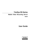
Example of Entry/Exit Zone WITH Security S witch Usage
Fo r Entry Zone :
Entr
Surveillance zone
DISARM
Alarm
Alarm
Alarm
Alarm
TeleEye RX
Security
Delay
Delay
Delay
Delay
Time line
Fig 8.1.3a
The entry delay is the period of time between entering the surveillance zone and reaching
the transmitter. In order to disarm the system for maintenance or repair, user / installer
needs to turn off the security sw itch and enter the surveillance zone. H owever, the delay
time starts from the 1st trigger by the 1st alarm sensor (i.e. Alarm 4). Note that if user
enables recording action, recording action is automatically activated during entry delay.
The detail procedure is as below:
1) user turns off security switch
2) the alarm is at entry delay
3) the 1st trigger is made by Alarm 4 (i.e. user enter the surveillance zone and the entry
delay time begin)
4) 2nd, 3rd and 4th trigger are made and each entry delay starts respectively
5) user disarms the system for maintenance
For example: If the time for going from security sw itch to transmitter is about 8 minutes,
Delay 1 should be longer than 8 minutes, while Delay 2 should be longer than the time for
going from security switch to Alarm 2, and so on.
Alarm
TeleEye Reception Software WX-30 Use r Manual
PAGE 101
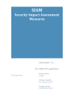
Fo r Exit Zone :
Exit
Surveillance zone
ARM
Alarm
Alarm
Alarm
Alarm
Security
TeleEye RX
Delay
Delay
Delay
Delay
Time line
Fig 8.1.3b
The exit delay is the period of time for leaving a surveillance zone without making false
alarm (i.e. A larm 1, Alarm 2, Alarm 3 and Alarm 4). The purpose is to let the user /
installer have enough of time to leave the surveillance zone after the transmitter is armed.
User / installer can set the delay time for each alarm.
The detail procedure is as below:
1) user arms the system
2) the alarm is at exit delay
3) the 1st trigger is made by Alarm 1 (i.e. user leave the surveillance zone and the exit
delay time begin)
4) 2nd, 3rd and 4th trigger are made and each exit delay starts respectively
5) user turns off the security switch or waits for any alarm exit delay to expire.
For example, if the time for leaving the surveillance zone is about 8 minutes, user should
adjust the delay time so that Delay 1 = leaving time between transmitter and Alarm 1,
Delay 2 = leaving time between transmitter and A larm 2, Delay 3 = leaving time between
transmitter and Alarm 3 and Delay 4 = 8 minutes. The alarm w ill be activated after the exit
delay expired. Note that if user enables recording action, recording action is automatically
activated during exit delay.
Alarm
TeleEye Reception Software WX-30 Use r Manual
PAGE 102
Example of Entry/Exit Zone WITHOUT Security Switch Usage
Fo r Entry Zone :
Entry
Surveillance zone
DISARM
Alarm
Alarm
Alarm
Alarm
Delay
Delay
Delay
Delay
TeleEye RX
Time line
Fig 8.1.3c
The entry delay is the period of time between entering the surveillance zone and reaching
the transmitter. In order to disarm the system for maintenance or repair, user / installer
enters the surveillance zone, and the delay time starts from the 1st trigger by the 1st alarm
sensor (i.e. Alarm 4) automatically. Note that if user enables recording action, recording
action is automatically activated during entry delay.
The detail procedure is as below:
1) the alarm is at entry delay
2) the 1st trigger is made by Alarm 4 (i.e. user enter the surveillance zone and the entry
delay time begin)
3) 2nd, 3rd and 4th trigger are made and each entry delay starts respectively
4) user disarms the system for maintenance
For example: If the time for going from Alarm 4 to transmitter is about 8 minutes, Delay 1
should be longer than 8 minutes, while Delay 2 should be longer than the time for going
from security switch to Alarm 2, and so on.
Alarm
TeleEye Reception Software WX-30 Use r Manual
Fo r Exit Zone :
PAGE 103
Exit
Surveillance zone
ARM
Alarm
Alarm
Alarm
Alarm
Delay
Delay
Delay
Delay
TeleEye RX
Time line
Fig 8.1.3d
The exit delay is the period of time for leaving a surveillance zone without making false
alarm (i.e. A larm 1, Alarm 2, Alarm 3 and Alarm 4). The purpose is to let the user /
installer have enough of time to leave the surveillance zone after the transmitter is armed.
User / installer can set the delay time for each alarm.
The detail procedure is as below:
1) user arms the system
2) the alarm moves to exit delay
3) the 1st trigger is made by A larm1 (i.e. user leave the surveillance zone and the exit
delay time begin)
4) 2nd, 3rd and 4th trigger are made and each exit delay starts respectively
5) user waits for any alarm exit delay to expire.
For example, if the time for leaving the surveillance zone is about 8 minutes, user should
adjust the delay time so that Delay 1 = leaving time between transmitter and Alarm 1,
Delay 2 = leaving time between transmitter and A larm 2, Delay 3 = leaving time between
transmitter and Alarm 3 and Delay 4 = 8 minutes. The alarm w ill be activated after the exit
delay expired. Note that if user enables recording action, recording action is automatically
activated during exit delay.
Alarm
TeleEye Reception Software WX-30 Use r Manual
PAGE 104
Cases of Arm/Disarm, Se curity Switch and Alarm for the 3 Zone Type
Initial S tate
S tep 1
Arm
S ecurity S witch
S tep 2
Step 3
Result
Alarm
Fi re Zone
Arm
On
No trigger
T rigger alarm
\
\
Alarm t rigger
Arm
Off
No trigger
T rigger alarm
\
\
Alarm t rigger
Arm
Uninstall
No trigger
T rigger alarm
\
\
Alarm t rigger
Disarm
\
No trigger
T rigger alarm
\
\
Alarm t rigger
Uninstall
\
No trigger
T rigger alarm
\
\
Alarm t rigger
Uninstall
Uninstall
No trigger
T rigger alarm
\
\
Alarm t rigger
Normal
Arm
On
No trigger
T rigger alarm
\
\
Alarm t rigger
Arm
Off
No trigger
T rigger alarm
\
\
Alarm t rigger
Arm
Uninstall
No trigger
T rigger alarm
\
\
Alarm t rigger
Disarm
\
No trigger
T rigger alarm
\
\
No alarm trigger
Uninstall
\
No trigger
T rigger alarm
\
\
Alarm t rigger
Uninstall
Uninstall
No trigger
T rigger alarm
\
\
Alarm t rigger
\
Alarm t rigger
Security swit ch on.
Alarm can be
Exit delay ends.
triggered any time
Recording stops
after that
En try / Exit Zone
Arm
On
No trigger
T rigger alarm
\
T rigger alarm.
Exit delay starts.
Disarm
Off
No trigger
Arm
Recording st arts
(if recording
action is enabled)
Security swit ch off.
Exit delay ends aft er
the pres et exit time
value.
Alarm can be
Recording stops
triggered any time
after that
Alarm
TeleEye Reception Software WX-30 Use r Manual
PAGE 105
Initial S tate
S tep 1
Arm
S ecurity S witch
S tep 2
Step 3
Result
Alarm
Entry / Exit Zone
No alarm trigger.
T rigger alarm.
Disarm
Recording stops
Entry delay st arts .
Security swit ch
Arm
On
No trigger
Recording st arts
Alarm is triggered
off
(if recording
action is enabled)
Recording does not
Arm
stop unless user
disarm the syst em
T rigger alarm.
Exit delay ends aft er
T he system will ent er
the pres et exit time
entry delay
value.
automatically after
Recording stops
next alarm trigger
Exit delay starts.
Disarm
Uninstall
No trigger
Arm
Recording st arts
(if recording
action is enabled)
T rigger alarm .
No alarm trigger.
Disarm
\
Entry delay
Recording stops .
starts.
Arm
Uninstall
No trigger
Alarm is triggered.
Recording st arts
(if recording
Recording does not
Arm
\
stop unless user
action is enabled)
disarm the syst em.
Disarm
No trigger
T rigger alarm
\
\
No alarm trigger
Uninstall
No trigger
T rigger alarm
\
\
Alarm t rigger
No trigger
T rigger alarm
\
\
Alarm t rigger
Uninstall
Uninstall
Alarm
TeleEye Reception Software WX-30 Use r Manual
PAGE 106
Alarm Setup Procedure :
St ep 1 : In {Transmitter S etup} p anel, click [Even t] [Alarm] [S ensor (N o.)] opt ion to pop up {S ensor
(No.) S etting} p anel as Fig 8.1.3e.
Fig 8.1.3e
St ep 2 :
Click [En abled] checkbox t o
enable the alarm s ens or.
Fi g 8.1.3f
St ep 3 :
Edit the name of the alarm
sens or.
Fi g 8.1.3g
St ep 4 :
Click [O pen] or [Close] for
sens or type option.
Fi g 8.1.3h
Alarm
TeleEye Reception Software WX-30 Use r Manual
St ep 5 :
PAGE 107
Click [N one], [S EO L] or
[DEO L] option for tamper
type.
Fi g 8.1.3i
St ep 6 :
Click [Norm al], [Fi re Zone ]
or [En try/Exi t Zone] option
for zone type. If [En try/Exi t
Zone] is s elected, please select
[Entry
Fi g 8.1.3j
Delay]
and
[Exi t
Delay] for the entry/exit zone.
St ep 7 : A fter s etting all alarms, us er can view the alarm s etting s ummary in {Transmi tte r S etup} panel by
clicking [Event] [Al arm] option to pop up {Alarm S etting Summary} panel as Fi g 8.1.3k
Fig 8.1.3k
Alarm
TeleEye Reception Software WX-30 Use r Manual
St ep 8 :
PAGE 108
Press
[Apply]
button
on
{Transmi tte r S etup} panel t o
Fi g 8.1.3l
save
the
setting
to
t he
transmitter.
Setup throug h Alarm Setting Summary Pro cedure :
User can us e {Al arm S etting S ummary} panel as a quick way to do t he alarm s ettings .
St ep 1 :
On
the
{Al arm
S etting
S ummary} panel, user can
click
the
boxes
under
[Enabled], [Type], [Tampe r],
Fi g 8.1.3m
[Zone ] or those act ions, in t he
sum mary to change the alarm
enable, alarm type, tamper
type, zone type and other
Fi g 8.1.3n
action options for the alarm
event as shown on Fi g 8.1.3m
~ Fi g 8.1.3p.
Fi g 8.1.3o
Fi g 8.1.3p
OR
Alarm
TeleEye Reception Software WX-30 Use r Manual
St ep 1 :
PAGE 109
Or,
user
can
click
t he
[Enabled], [Type ], [Tamper]
or [Zone] t o choose all alarm
for the s ame alarm s etting as
Fi g 8.1.3q
shown on Fig 8.1.3q ~ Fi g
8.1.3t.
Fi g 8.1.3r
Fi g 8.1.3s
Fi g 8.1.3t
St ep 2 :
Press
[Apply]
button
on
{Transmi tte r S etup} panel t o
Fi g 8.1.3u
save
the
transmitter.
Alarm
setting
to
t he
TeleEye Reception Software WX-30 Use r Manual
PAGE 110
8.1.4 Motion
Motio n
Motion detection can be triggered when motion occurs on the camera. Motion detection
has different sensitivity levels. For motion event on each video input channel, it depends
on the motion of selected area. User should setup the motion areas and sensitivity. Motion
detection has generally 4 options : high, middle, lo w and custo m. Custom option allow s
user to select the sensitivity level and area by himself/herself.
Motio n De tectio n Ex ample
If motion detection is enabled, object movement is captured by the camera as shown below.
Fig 8 .1 .4a shows motion detection. The normal display area is the selected motion
detection area. The blue area cannot detect any motion. M otion block is activated when
there is any movement on the camera.
Fig 8.1.4a
Motion
Mo tio n Block
TeleEye Reception Software WX-30 Use r Manual
PAGE 111
Sensitivity
Level
The level definition of motion detection is due to the luminance level difference between
current and reference field. The level has 10 levels, H is the most sensitive and L is the
least sensitive.
Area
In motion detection, o ne selected motion block is divided into
four sub-blocks as Fig 8.1.4 b. The definition of area is how many
sub-blocks have detected motion in order to trigger a motion
event. The range of area option is 25% (1 block) to 100% (4
blocks). More blocks are selected, the motion trigger sensitivity
decrease.
Fi g 8.1.4b
Motio n Setup Pro cedure :
St ep 1 : In {Transmitter S etup} panel, click [Eve nt] [Motion] [Cam (N o.)] option to pop up {Motion
Setting} panel as Fi g 8.1.4c.
Motion
TeleEye Reception Software WX-30 Use r Manual
PAGE 112
Fig 8.1.4c
St ep 2 :
Click [En abled] checkbox t o
enable the motion det ection
Fi g 8.1.4d
function for the camera.
St ep 3 :
Click [Motion S etting] t o
open {Motion S etting} pop up
windows .
Click [S elect] to s elect t he
required motion blocks. Click
[Deselect]
selected
to
delete
mot ion
t he
blocks .
[S elect All] is t o s elect all
motion block on the s creen.
[Deselect All] is to delete all
motion blocks on the s creen.
Fi g 8.1.4e
St ep 4 :
Click
[High],
[Medium],
[Low] or [Custom] for motion
sens itivity.
Fi g 8.1.4f
Motion
TeleEye Reception Software WX-30 Use r Manual
St ep 5 :
PAGE 113
If
[Custom]
sensit ivity is
selected, us er can select le vel
and area for sensitivity by
click [Le vel] or [Are a] scroll
bar.
Fi g 8.1.4g
St ep 6 : After setting all camera for mot ion, user can view the alarm s etting summary in {Transmitter S etup}
panel by clicking [Eve nt] [Moti on ] option t o pop up {M otion S etting S ummary} panel as Fi g 8.1.4h
Fig 8.1.4h
St ep 8 :
Press
[Apply]
button
on
{Transmi tte r S etup} panel t o
Fi g 8.1.3i
save
the
transmitter.
Motion
setting
to
t he
TeleEye Reception Software WX-30 Use r Manual
PAGE 114
Setup throug h Mo tio n Setting Summary Pro ce dure :
User can us e {Moti on S etting S ummary} panel as a quick way t o do the alarm settings.
St ep 1 :
On
the
{Moti on
S etting
S ummary} panel, user can
click
the
boxes
under
[Enabled], [Le vel ] or thos e
Fi g 8.1.4j
actions, in the s um mary t o
change the m otion enable,
sens itivity
level,
or
other
action options for the motion
Fi g 8.1.4k
event as s hown on Fig 8.1.3j
and Fig 8.1.3k.
OR
St ep 1 :
Or,
user
[Enabled]
can
or
click
t he
[Le vel]
to
choose all cameras for t he
sam e m otion settings as s hown
Fi g 8.1.4l
on Fig 8.1.3l and Fig 8.1.3m.
Fi g 8.1.4m
St ep 2 :
Press
[Apply]
button
on
{Transmi tte r S etup} panel t o
Fi g 8.1.4n
save
the
transmitter.
Motion
setting
to
t he
TeleEye Reception Software WX-30 Use r Manual
PAGE 115
8.1.5 Video Loss
Video Loss
Video loss can be triggered when the video channel input disappears. It will happen if the
transmitter receives no signal from the camera. The live camera displays a blue picture for
video loss condition.
Video Loss Se tup Procedure :
St ep 1 : In {Transmitter S etup} p anel, click [Event] [Vi deo Loss] [Cam (No.)] option to p op up {Video
Loss S etting} panel as Fig 8.1.5a.
Fig 8.1.5a
St ep 2 :
Click [En abled] checkbox t o
enable the video loss function
Fi g 8.1.5b
Video Loss
for the camera.
TeleEye Reception Software WX-30 Use r Manual
PAGE 116
St ep 3 : Aft er s etting video loss function for all cam eras, us er can view the video los s s etting s ummary in
{Transmitter S etup} p anel by clicking [Even t] [Vi deo Loss ] option t o pop up {Vi deo Loss S etting
S ummary} panel as Fig 8.1.5c
Fig 8.1.5c
St ep 8 :
Press
[Apply]
button
on
{Transmi tte r S etup} panel t o
Fi g 8.1.3d
save
the
transmitter.
Video Loss
setting
to
t he
TeleEye Reception Software WX-30 Use r Manual
PAGE 117
Setup throug h Video Loss Setting Summary Procedure :
User can us e {Vi deo Loss S etting S ummary} panel as a quick w ay to do t he alarm settings .
St ep 1 :
On the {Vi deo Loss S etting
S ummary} panel, user can
click
the
boxes
under
[Enabled] or ot her actions in
the summary to change t he
Fi g 8.1.5e
options for the video los s
event as s hown on Fig 8.1.5e.
OR
St ep 1 :
Or, us er can click [En abled]
box to enable or disable video
loss event for all cameras as
shown on Fig 8.1.5f.
Fi g 8.1.5f
St ep 2 :
Press
[Apply]
button
on
{Transmi tte r S etup} panel t o
Fi g 8.1.5g
save
the
transmitter.
Video Loss
setting
to
t he
TeleEye Reception Software WX-30 Use r Manual
PAGE 118
8.1.6 System Tamper
System Tamper Input
It is an input to the transmitter for wiring a tamper sw itch of the external cabinet outside the
transmitter and its accessories. T he purpose of system tamper event is to prevent some one
to break into the cabinet and destroy the transmitter.
Sensor Type
The system tamper input circuit type is normal clo se (NC). The state of the circuit is close,
it indicates normal of TeleEye RX. Otherwise, the state of the circuit is o pe n, it indicates
syste m tamper of TeleEye RX. The system tamper input circuit type is no rmal o pe n
(NO). The state of the circuit is open, it indicates no rmal of TeleEye RX. Otherwise, the
state of the circuit is close , it indicates system tampe r of TeleEye RX.
System Tamper Se tup Procedure :
St ep 1 : In {Transmitter S etup} panel, click [Eve nt] [S ystem Tam per Input] option t o pop up {S ystem
Tamper Input S etting} panel as Fi g 8.1.6a
Fig 8.1.6a
System Tamper
TeleEye Reception Software WX-30 Use r Manual
St ep 2 :
PAGE 119
Click [En abled] checkbox t o
enable system tamper inp ut.
Fi g 8.16b
St ep 3 :
Click [O pen] or [Close] for
sens or type option.
Fig 8.16c
St ep 4 :
Press
[Apply]
button
on
{Transmi tte r S etup} panel t o
Fi g 8.1.6d
save
the
transmitter.
System Tamper
setting
to
t he
TeleEye Reception Software WX-30 Use r Manual
PAGE 120
8.1.7 Power Failure
Power Failure Input
It is an input to the transmitter typically used for wiring the output signal pin from UPS.
Sensor Type
The power failure input circuit type is normal close (NC). The state of the circuit is close,
it indicates normal of TeleE ye RX. Otherwise, the state of the circuit is open, it
indicates po wer failu re of TeleEye RX. The power failure input circuit type is normal
open (NO). The state of the circuit is o pe n, it indicates normal of TeleEye RX.
Otherw ise, the state of the circuit is clo se , it indicates po we r failure of TeleEye RX.
Power Failure Setup Pro cedure :
St ep 1 : In {Tran smitte r S etup} panel, click [Event] [Power Failu re Input] option to pop up {Power Failure
Input S etting} panel as Fig 8.1.7a
Fig 8.1.7a
Power Failure
TeleEye Reception Software WX-30 Use r Manual
St ep 2 :
PAGE 121
Click [En abled] checkbox t o
enable power failure inp ut.
Fi g 8.17b
St ep 3 :
Click [O pen] or [Close] for
sens or type option.
Fig 8.17c
St ep 4 :
Press
[Apply]
button
on
{Transmi tte r S etup} panel t o
Fi g 8.1.7d
save
the
transmitter.
Power Failure
setting
to
t he
TeleEye Reception Software WX-30 Use r Manual
8.2
PAGE 122
Action
TeleEye RX supports 8 actions which can be activated by any events
1 . Live Came ra
2 . Recording
3 . Switch
4 . Dial b ack
5 . PTZ
6 . Event LED
7 . Buzze r
8 . Spo t Alarm
User can set an event to activate its associate action. Fig 8 .2a shows the event action summary
for all events
Action Setting Pro cedure :
St ep 1 : In {Tran smitte r S etup} panel, click [Event] Any event [Action] option to pop up {(Event) Action}
panel as shown on Fig 8.2a.
Action
TeleEye Reception Software WX-30 Use r Manual
PAGE 123
Fi g 8.2a
OR
St ep 1 : In {Tran smitte r S etup} panel, click [Eve nt] Any event option to pop up any event setting panel. C lick
[Action] button near [En abled] checkbox to pop up {(Event) Action } p anel as show n on Fig 8.2b.
Fi g 8.2b
St ep 2 : Us er can select the action s etting for that event as s hown on Fi g 8.2c.
Fi g 8.2c
Action
TeleEye Reception Software WX-30 Use r Manual
PAGE 124
8.2.1 Live Camera
Live Came ra
Event associate live camera display real time live video of pre-selected camera if an event
triggers, so operator can immediately know what happen from the site. Live camera action
can only display live video o ne time before user clears the event.
Live Came ra Se tup Procedure :
St ep 1 : In {(Eve nt) Action} panel, click [Li ve ] option t o s et live camera s etting as Fig 8.2.1a.
Fig 8.2.1a
St ep 2 :
Fi g 8.2.1b
Click [En able As soci ate Li ve
Cameras ] checkbox to enable
the live camera for that event.
Live Camera
TeleEye Reception Software WX-30 Use r Manual
St ep 3 :
PAGE 125
Click the checkbox for t he
cam era to select which cam era
for the live cam era action.
[S elect All] option is
for
selecting all cameras. [S elect
Fi g 8.2.1c
None] option is for selecting
no camera. However, user
needs to select at least one
cam era for the act ion.
St ep 4 :
Press
[Apply]
button
on
{Transmi tte r S etup} panel t o
Fi g 8.2.1d
save
the
transmitter.
Live Camera
setting
to
t he
TeleEye Reception Software WX-30 Use r Manual
PAGE 126
8.2.2 Recording
Recording
If an event triggers, recording can record the video content at user selected camera with
selected recording mode.
Pre-Alarm Recording
Pre-alarm recording allow s to record video before an event trigger. The period of pre-alarm
recording is at least 1 minute (not more than 2 minutes) before the event trigger. User can
find that there is at least 1 minute more video content on {Search Playb ack Log} panel
before event trigger.
Duration Afte r Event Cle ar
After event resets, the recording action will stop after this duration time.
Recording Mode
Event recording provides 2 recording modes, 1 frame pe r second (1 FPS) and continuous
mo de. In 1 FP S mode, the recording frame rate is less, so the storage size is small. In
continuous mode, the recording frame rate depends on the number of recording camera and
more than 1 FPS, so the storage size is larger.
Disk Mo de
Cyclic disk mode can erase the oldest recording data in hard disk if the hard disk is full,
and continue to record video. F ix disk mode need to sto p all re co rding if hard disk is full.
Quality
This is the quality of the recorded video. T he quality is divided into 5 levels (in ascending
quality order) : low, fair, medium, good and ex ce llent.
Resolution
This is the display resolution for the recorded video. Full is the resolution suitable for full
size display. Quad is the resolution suitable for quarter size display. During playback, quad
resolution video may have several noise in full size display mode.
Recording
TeleEye Reception Software WX-30 Use r Manual
PAGE 127
Recording Setup Pro cedure :
St ep 1 : In {(Eve nt) Action} panel, click [Re cordi ng] option to s et recording setting as Fi g 8.2.2a.
Fig 8.2.2a
St ep 2 :
Click
[Enable
Recordi ng]
checkbox to enable recording
Fi g 8.2.2b
for that event.
St ep 3 :
Click the checkbox for t he
cam era to select which cam era
for
t he
recording
act ion.
[S elect All] option is
Fi g 8.2.2c
for
selecting all cameras. [S elect
None] option is for selecting
no camera. However, user
needs to select at least one
cam era for the act ion.
Recording
TeleEye Reception Software WX-30 Use r Manual
St ep 4 :
PAGE 128
Click [1fps] or [C onti nuous ]
option for recording m ode.
Fi g 8.2.2d
St ep 5 :
Click [On e vent clear, s top
recordi ng afte r] to s elect t he
time for durat ion after event
clear.
Fi g 8.2.2e
St ep 6 :
Click
[Recordin g
S etting]
button to pop up {Recording
Fi g 8.2.2f
S ettings} panel as Fi g 8.2.2g.
The options in {Recording Setting s} panel are glo bal se ttings that means these
settings apply to all event and manual recording actions. User may need to do this
setting once.
Recording
TeleEye Reception Software WX-30 Use r Manual
PAGE 129
Fig 8.2.2g
St ep 7 :
Click [Cyclic]
or
[Fixed]
option for dis k mode.
Fi g 8.2.2h
St ep 8 :
Move the s croll bar to adjust
[Quality]. Click [FULL] or
[QUAD] option for image
size. P ress [OK ] button to exit
the panel.
Fi g 8.2.2i
St ep 9 :
Press
[Apply]
button
on
{Transmi tte r S etup} panel t o
Fi g 8.2.2j
save
the
transmitter.
Recording
setting
to
t he
TeleEye Reception Software WX-30 Use r Manual
PAGE 130
8.2.3 Switch
Switch allows transmitter to control 4 external relays which are defined by user.
Switch T ype
Switch has 2 types. They are latching or push-button type. In latching type, the switch
turns on for a period of time. In push-button type, the switch turns on and off after 1
second.
Latching Duration
The latch duration period is the time for turning on the switch.
Action Delay
The delay is the period of time after turning off the switch before next turning on.
Latching Duration and Action Delay Example
For latch type sw itch, set latch duration 10sec
and action delay 10sec. If an event trigger, the
timing of the switch is shown on the right.
Fig 8.2.3a
For push-button type switch, set latch duration 10sec and
action delay 10sec. If an event trigger, the timing of the
switch is shown on the right.
Switch
Fig 8.2.3b
TeleEye Reception Software WX-30 Use r Manual
PAGE 131
Switch Setup Procedure :
St ep 1 : In {(Eve nt) Action} panel, click [S witch] option to s et swit ch s etting as Fi g 8.2.3c.
Fig 8.2.3c
St ep 2 :
Click
[Enable
S witch
Control] checkbox to enable
Fi g 8.2.3d
switch action for that event.
St ep 3 :
Click [En able S witch (No.)]
checkbox t o enable which
switch for that event.
Fi g 8.2.3e
St ep 4 :
Fi g 8.2.3f
Click [S witch S ettings] button
to pop up {S witch S ettings }
panel as Fig 8.2.3g.
Switch
TeleEye Reception Software WX-30 Use r Manual
PAGE 132
The options in {Switch Se ttings} panel are global se ttings that means these settings
apply to all switch actions. User may need to do this setting once.
Fig 8.2.3g
St ep 5 :
Edit the name of the swit ch.
St ep 6 :
Click
Fi g 8.2.3h
[Push
B utton]
or
[Latching] option for swit ch
Fi g 8.2.3i
type.
St ep 7 :
Click [Event Action Delay] t o
select the time switch action
delay. Click [Even t Latch
Duration] t o s elect the time
switch latch duration. Pres s
Fi g 8.2.3j
Switch
[OK] button to exit t he p anel.
TeleEye Reception Software WX-30 Use r Manual
St ep 8 :
PAGE 133
Press
[Apply]
button
on
{Transmi tte r S etup} panel t o
Fi g 8.2.3k
save
the
transmitter.
Switch
setting
to
t he
TeleEye Reception Software WX-30 Use r Manual
PAGE 134
8.2.4 Dial Back
Dial Back
Dial back allows the transmitter to connect to o ne remote P C and displays live video if an
event triggers. T herefore, remote operator can recognize what situation is at the
surveillance area.
Retry Du ratio n
The retry duration is the period between each dial back retrial (in second).
Retry Co unt
The retry count is the number of dial back retrial if dial back fails.
Dial Back Setup Pro cedure :
St ep 1 : In {(Eve nt) Action} panel, click [Dial Back] option t o s et dial back s etting as Fi g 8.2.4a.
Fig 8.2.4a
Dial Back
TeleEye Reception Software WX-30 Use r Manual
St ep 2 :
PAGE 135
Click [Enable Dial Back]
checkbox to enable dial back
Fi g 8.2.4b
for that event.
St ep 3 :
Click [Dial B ack S ettings ]
button to pop up {Dial-back
Fi g 8.2.4b
Entry} panel as Fig 8.2.4c.
The options in {Dial-back Entry} panel are g lobal se ttings that means these settings
apply to all dial back actions. User may need to do this setting once.
Fig 8.2.4c
St ep 4 :
Fi g 8.2.4d
Enter the dial back IP addres s
and the port number of the PC.
Since dial back allows the transmitter to connect to o ne remote P C only, the transmitter
will try to connect to the 1st IP entry, then 2nd entry, etc. The PC with 1st dial back IP
entry has the highest dial back priority.
Dial Back
TeleEye Reception Software WX-30 Use r Manual
St ep 5 :
PAGE 136
Select [Reconnect Durati on]
for choos ing the time of dial
Fi g 8.2.4e
back retry duration.
St ep 6 :
Select
[Re try
Cou nt]
for
choosing the num ber of dial
Fi g 8.2.4f
back fail retry. Press [O K]
button t o exit the p anel.
St ep 7 :
Press
[Apply]
button
on
{Transmi tte r S etup} panel t o
Fi g 8.2.4g
save
the
setting
to
t he
transmitter. Press [Close] t o
exit the p anel and go back t o
the main panel.
St ep 8 : Click [Al arm S tandby]
icon on t he main p anel as s how n on Fig 8.2.4h.
Fig 8.2.4h
Dial Back
TeleEye Reception Software WX-30 Use r Manual
St ep 9 :
PAGE 137
Enter the alarm passw ord. T he
default
alarm p assword is
000000
Fi g 8.2.4i
St ep 10 :
{Standby Devi ce} panel pop
up. Press the icon
to
select the connect ion type for
dial back. Pres s the icon
to ent er {Connection S pee d}
Fi g 8.2.4j
panel.
St ep 11 :
Select bit rat e, port number for
the
connect ion.
T he
p ort
number s hould be as same as
the port num ber s et in s tep 4.
Press [OK] icon to exit and
save the s ettings
Fi g 8.2.4k
Dial Back
TeleEye Reception Software WX-30 Use r Manual
PAGE 138
8.2.5 Pan Tilt Zoom (PTZ)
PTZ Came ra
PTZ camera action allows the pan tilt zoom camera to go to user preset position for
viewing what happen if an event trigger.
PTZ Setup Procedure :
St ep 1 : In {(Eve nt) Action} panel, click [PTZ] option t o s et p an tilt zoom camera s etting as Fig 8.2.5a.
Fig 8.2.5a
St ep 2 :
Fi g 8.2.5b
Click [Enable Preset PT Z]
checkbox to enable pan tilt
zoom cam era for that event.
Pan Tilt Zoom (PTZ)
TeleEye Reception Software WX-30 Use r Manual
St ep 3 :
PAGE 139
Click the checkbox for t he
cam era to select which cam era
for the PTZ camera action.
[S elect All] option is
for
selecting all cameras. [S elect
Fi g 8.2.5c
None] option is for selecting
no camera. However, user
needs to select at least one
cam era for the act ion.
St ep 4 :
Click [Prese t No.] to select
the preset position for the PTZ
cam era t o go to if the event
trigger.
Fi g 8.2.5d
For the detail of s ett ing the PT Z preset position, pleas e refer to P.125 of Sect ion 9.1: PTZ Settings. It is
strong recommended to go through Section 9.1 before do t he PT Z action settings.
St ep 5 :
Press
[Apply]
button
on
{Transmi tte r S etup} panel t o
Fi g 8.2.5e
save
the
transmitter.
Pan Tilt Zoom (PTZ)
setting
to
t he
TeleEye Reception Software WX-30 Use r Manual
PAGE 140
8.2.6 Event LED
Event LED
The event LED is the LED built on the front panel of TeleE ye RX transmitter
. If an
event trigger, the LED is blinking until the event is clear.
Event LED Setup Procedure :
St ep 1 : In {(Eve nt) Action} panel, click [Event LED ] option to s et event LED s etting as Fi g 8.2.6a.
Fig 8.2.6a
St ep 2 :
Click [Enable Transmi tter
Eve nt
Fi g 8.2.6b
LED] checkbox t o
enable event LED for that
event.
St ep 3 :
Press
[Apply]
button
on
{Transmi tte r S etup} panel t o
Fi g 8.2.6c
save
the
transmitter.
Event LED
setting
to
t he
TeleEye Reception Software WX-30 Use r Manual
PAGE 141
8.2.7 Buzzer
Buzze r
This buzzer contains inside the TeleEye RX transmitter. It can produce “ Beep” sound in
order to draw nearby operator attention about an event trigger.
Duration
Duration is the period for turning on the buzzer.
Action Delay
Action delay is the period after turning off the buzzer turning on.
Buzze r Setup Procedure :
St ep 1 : In {(Eve nt) Action} panel, click [Buzzer] option t o s et buzz er setting as Fi g 8.2.7a.
Fig 8.2.7a
Buzzer
TeleEye Reception Software WX-30 Use r Manual
St ep 2 :
PAGE 142
Click
[En able
Buzzer]
checkbox to enable buzz er for
Fi g 8.2.7b
that event.
St ep 3 :
Click
[Buzze r
S ettings ]
button to pop up {Buzzer
Fi g 8.2.7c
S ettings} panel as Fi g 8.2.7d.
The options in {Buzzer Se ttings} panel are global settings that means these settings
apply to all buzzer actions. User may need to do this setting once.
St ep 4 :
Click [Action Duration] t o
select the time for buzzer
action duration. Click [Action
Delay] to select t he time for
buzz er action delay. Pres s
[OK] button to exit t he p anel.
Fi g 8.2.7d
St ep 5 :
Press
[Apply]
button
on
{Transmi tte r S etup} panel t o
Fi g 8.2.7e
save
the
transmitter.
Buzzer
setting
to
t he
TeleEye Reception Software WX-30 Use r Manual
PAGE 143
8.2.8 Spot Alarm
Spo t Alarm Setup Procedure :
St ep 1 : In {(Eve nt) Action} panel, click [Li ve ] option t o s et live camera s etting as Fig 8.2.8a.
Fig 8.2.8a
St ep 2 :
Click [Enable S pot Alarm]
Fi g 8.2.8b
checkbox for that event.
St ep 3 :
Select the cam era(s ) for t he
live
cam era
act ion.
It
is
needed to s elect at leas t one
cam era for this act ion.
Fi g 8.2.8c
St ep 4 :
Click [Appl y] button to s ave
the s ettings.
Fi g 8.2.8d
Buzzer
TeleEye Reception Software WX-30 Use r Manual
PAGE 144
8.2.9 Email Setup :
St ep 1 : In {Tran smitte r S etup} panel, click [Eve nt] [Alarm] [sens or (No.)] [Action] [E-mail]
option t o s etup email as Fi g 8.29a.
Fig 8.29a
St ep 2 :
Fi g 8.29b
Buzzer
Click [E-mail S ettings… ]
TeleEye Reception Software WX-30 Use r Manual
St ep 3 :
PAGE 145
Click[Enable Authen ticati on]
to enable the aut hentication.
Input the E-mail Address and
the Sender Email.
Fi g 8.2.9c
St ep 4 :
Fi g 8.2.9d
Buzzer
Click [OK] button to save t he
setting of t he e-mail
TeleEye Reception Software WX-30 Use r Manual
PAGE 146
8.2.10 SMS Setup :
St ep 1 : In {(Eve nt) Action} panel, click [S MS ] option to set SMS s etting as Fig 8.2.5a.
St ep 2 : Click [Enable S MS ] button to enable SM S
St ep 3 : Press [S MS S ettings…] to op en {S MS Settings} panel
Step 4: Enter the information in the provided fields and click [OK] button to apply the settings.
Step 5 (Optional): Click [SMS Test…] to perform SMS testing.
Buzzer
TeleEye Reception Software WX-30 Use r Manual
PAGE 147
8.2.11 Dialback Test:
St ep 1 : In {Tran smitte r S etup} panel, click [Eve nt] [Alarm] [sens or (No.)] [Action] [Dial Back ]
option t o s etup email as Fi g 8.211a.
Fig 8.211a
St ep 2 :
Fi g 8.211b
Buzzer
Click [Dialback Test…]
TeleEye Reception Software WX-30 Use r Manual
PAGE 148
St ep 3 :
Click [Start Test].
St ep 4 :
Test result will show in t he
Fi g 8.2.11c
status.
Fi g 8.2.11d
Buzzer
TeleEye Reception Software WX-30 Use r Manual
8.3
PAGE 149
Event Indication
TeleEye Reception Software WX-30 has user friendly event display interface and accurate
event log. User can realize event trigger through different panels on the interface or read the
event log.
1.
Event Pane l
2.
Event Status
3.
Event Log
Event Indication
TeleEye Reception Software WX-30 Use r Manual
PAGE 150
8.3.1 Event Panel
Event panel is located at the main panel as shown in Fig 8 .3.1a. It shows the instantaneous
event status to users.
Fig 8.3.1a
Event Pane l Button Indication Table
Button
Meaning
Sw itch t he [Even t] panel to alarm mode
Sw itch t he [Even t] panel to m otion mode
Sw itch t he [Even t] panel to tamper mode
Sw itch t he [Even t] panel to system mode
Sw itch t he [Even t] panel to video loss mode
Event Panel
TeleEye Reception Software WX-30 Use r Manual
PAGE 151
Event Pane l Ico n Indication Table
Icon
Ico n Status
S ymbol “ – ”
When t he corresponding camera is not inst alled
S ymbol “O ”
A selected event corresp onding to the camera triggering/triggered.
Green “O ”
A selected event corresp onding to the camera triggered and not cleared.
Re d “O ”
A selected event corresp onding to the camera is triggering.
Gray
No Dis k Usage event triggered/triggering or t his checking is not enabled.
Green
Disk Usage event is triggered and not cleared.
Red
Disk Usage event is triggering.
Gray
No Over Heat event t riggered/triggering or this checking is not enabled.
Green
Over H eat event is triggered and not cleared.
Red
Over H eat event is triggering.
Gray
No Power Failure event t riggered/triggering or this checking is not enabled.
Green
Pow er Failure event is triggered and not cleared.
Red
Pow er Failure event is triggering.
Gray
No System Tamper event triggered/triggering or t his checking is not enabled.
Green
event is t riggered and not cleared.
Red
event is t riggering.
Gray
No Alarm Tamper event triggered/triggering or t his checking is not enabled.
Green
Alarm Tamper event is triggered and not cleared.
Red
Event Panel
Me aning
Alarm Tamper event is triggering.
TeleEye Reception Software WX-30 Use r Manual
PAGE 152
Others Event Panel Ico n Indication Table
Colou r
Clear event if any event res et (green icon). If an event is trigger, it cannot be
cleared.
Event Panel
Dimmed
No event clear. It occurs if no event trigger or all events are triggering.
Colou r
Siren is turned on by event trigger
Dimmed
Siren is turned off if no event trigger or siren timeout.
Green
T he system is armed.
Red
T he system is disarmed.
Lock On
T he security switch is turned on.
Lock Off
T he security switch is turned off.
TeleEye Reception Software WX-30 Use r Manual
PAGE 153
8.3.2 Event Status
The event status can show the most update event status to user through log format.
Event Status Using Pro cedure :
St ep 1 : Click [Even t] [Even t S tatus] option on the main panel.
Fig 8.3.2a
St ep 2 : {Event S tatus} panel is shown on Fig 8.3.2b.
Fig 8.3.2b
Event Log
TeleEye Reception Software WX-30 Use r Manual
PAGE 154
Event Status Co lumn Descriptio n :
No.
The number of the event status
Date
Date of the event status
Time
Time of the event status
Transmitte r Name
The event triggers at which transmitter.
Event
What kind of event trigger
Source
The alarm sensor number & name or camera number & name of the event
Status
The status of the event. Trigger means the event is triggering. Reset means the event has
been triggered before without clear. Clear means the event has been cleared.
St ep 3 :
Click the checkbox to p op up
the st atus when event trigger.
Fi g 8.3.2c
Default is clicked.
St ep 4 :
Fi g 8.3.2d
User may clear the event
status by pressing [Clear]
button. P ress [Close] to clos e
the event status .
Event Log
TeleEye Reception Software WX-30 Use r Manual
8.3.3 Event Log
Event log record the event trigger status w ith the detail action taken.
Event Log Using Pro ce dure :
St ep 1 : Click [Even t] [Tran smitte r Log] [Event Log] opt ion on the m ain panel.
Fig 8.3.3a
Event Log
PAGE 155
TeleEye Reception Software WX-30 Use r Manual
PAGE 156
St ep 2 : {Remote Event Log} panel is shown on Fig 8.3.3b. User can s elect different event menu.
Fig 8.3.3b
Event Logs Column Description :
Date
It is the date when the event occurs.
Time
It is the time when the event occurs.
Alarm/Motio n/Video Loss
It is the alarm sensor number(Alarm Log), or the camera number(Motion and Video L oss
Log)
Event/State /Status
It is the event status, such as trigged, reset, cleared by user.
Action
It is the associate actions taken for the event
Event Log
TeleEye Reception Software WX-30 Use r Manual
PAGE 157
Conne ction Log Column Description :
Date
It is the date when the connected or disconnected.
Time
It is the time when the connected or disconnected.
Access Media
It is the connection media between the transmitter and the PC, such as TCP/IP or modem.
Type
It is the type of connection, either PC connect to the transmitter or the transmitter dial
back to P C by event action.
IP
It is the transmitter IP or phone number.
Status
It is the status of connection, either connected or disconnected.
St ep 3 :
Enter the page number and
press [Go] button t o go to t he
Fi g 8.3.3c
log p age, or pres s [Next]
button t o go to next log p age.
St ep 4 :
Fi g 8.3.3d
User may print out the event
log
report
print ing
[Pre view]
by
using
function.
t he
Pres s
icon to view
the remot e event log rep ort
first as shown on Fig 8.3.3e.
Event Log
TeleEye Reception Software WX-30 Use r Manual
PAGE 158
Fig 8.3.3e
St ep 5 :
Fi g 8.3.3e
Event Log
Press [Cancel] button to exit
{Remote Event Log} panel.
TeleEye Reception Software WX-30 Use r Manual
PAGE 159
8.3.4 Siren
The siren can produce a “Do n” sound in order to let user know an event trigger. User can set
duration time for turning on the siren if event trigger.
Sire n Duratio n Se tup Pro cedure :
St ep 1 : Click [Even t] [Al arm] [O pti on] option on the main panel to pop up {Alarm O ption} panel.
Fig 8.3.4a
St ep 2 :
Select
the time
for s iren
duration. Press [OK] button t o
complete t he setting.
Fi g 8.3.4b
Siren
TeleEye Reception Software WX-30 Use r Manual
PAGE 160
8.3.5 Clear Event
After an event reset, user can clear the event icon at the event panel. User needs to enter the
alarm passw ord in order to clear the event icon at the event panel.
Change Alarm Passwo rd Procedure :
St ep 1 : Click [Even t] [Al arm] [Alarm Password] option on the main panel.
Fig 8.3.5a
St ep 2 :
Enter old alarm passw ord, new
alarm password and confirm
the p assword again. Pres s
[OK] to complete the setting.
Fi g 8.3.5b
Default alarm password is 000000 . Alarm password is saved in your PC, not TeleEye
RX transmitter, so user can set different alarm password at different P C.
Clear Event
TeleEye Reception Software WX-30 Use r Manual
PAGE 161
Clear Event Ico n Procedure :
St ep 1 : Click [Clear Even t]
icon on the m ain p anel.
Fig 8.3.5c
St ep 2 :
Enter the alarm p assword.
Press [OK] button to clear t he
event icon.
Fi g 8.3.5d
Clear Event
TeleEye Reception Software WX-30 Use r Manual
PAGE 162
Section 9
Pan Tilt Zoom
9.1
PTZ Settings
TeleEye RX transmitter can control pan tilt zoom camera for remote monitoring. The pan tilt
zoom camera action can be activated by event triggered or manual control.
Pan Speed
The horizontal movement speed of the PTZ camera
Tilt Speed
The vertical movement speed of the PTZ camera
Pan Duration
The horizontal movement duration after pressing a [Left] or [Right] button
Tilt Duration
The vertical movement duration after pressing a [Up] or [Down] button
Zoo m Duration
The zoom in or out duration after pressing a [Zo om Tele] or [Zoo m Wide ] button
Iris Duration
The open or close of iris duration after pressing a [Open Iris] or [Close Iris] button
Focus Duration
The focus duration after pressing a [Fo cus Ne ar] or [Fo cus Far] button
Additional Duration
Some additional camera functions duration
Washe r Duratio n
The action time taken for the washer of the PTZ camera
PTZ Settings
TeleEye Reception Software WX-30 Use r Manual
PAGE 163
Wiper Duration
The action time taken for the wiper of the P TZ camera
Patrol Speed
The movement speed for one position to another position of the PTZ camera
Patrol Dwe ll Time
The time for the PTZ camera to stay at one position
Due to different PTZ camera supports different driver operation, some P TZ camera
settings may be dimmed. If there is any problem, please refer to the manual of the PTZ
camera to read if the PTZ have that function or not.
PTZ Setting Procedure :
St ep 1 : Click [Trans mitter S ettings] icon on the main panel and input the administrat or p assword to pop up
{Transmitter S ettings} p anel as s hown on Fi g 9.1a. Choos e [Vi deo In put][PTZ] option t o do t he
PT Z cam era s ettings.
Fi g 9.1a
PTZ Settings
TeleEye Reception Software WX-30 Use r Manual
St ep 2 :
PAGE 164
Select the suitable PT Z driver
and baud rat e according t o the
PT Z cam era.
Fig 9.1b
St ep 3 :
Click [PTZ] checkbox to enable
the camera as PT Z cam era.
Fig 9.1c
Change PT Z ID for external
keyboard if necessary.
Normally, the PTZ camera needs to install at the camera number according to its
camera ID in order to control it.
For furt her detail, please take a look on the camera or its manual in order to choos e the above settings.
St ep 4 : Aft er clicking [PT Z] checkbox in st ep 3, user can ent er {Pan Tilt Zoom} p anel by click [Pan Tilt Zoom]
icon on the main panel as s hown on Fig 9.1d.
Fi g 9.1d
PTZ Settings
TeleEye Reception Software WX-30 Use r Manual
PAGE 165
St ep 5 : {Pan Tilt Zoom} panel pop up. Us er can do other PTZ settings and control the camera through this panel.
Fi g 9.1e
St ep 6 :
User can s elect the PTZ driver
and which PT Z camera t o
view. T he cameras that can be
selected at [Camera] option
are t he cameras select ed at the
checkbox in step 3.
Fig 9.1f
The PTZ driver option in the panel CANNOT be saved in the transmitter, so it is used
for testing or temporally use only.
St ep 7 :
Scroll the [Pan S pee d] or
[Tilt S peed] bar t o select t he
Fig 9.1g
pan speed and tilt
respectively.
PTZ Settings
speed
TeleEye Reception Software WX-30 Use r Manual
St ep 8 :
PAGE 166
Press [PT Z S ettings ] button
on {Pan Tilt Zoom} panel t o
pop up this {S etting} panel t o
select
p an
duration,
tilt
duration, zoom duration, iris
duration, focus durat ion and
additional
duration
by
scrolling the bar. Press [O K]
Fig 9.1h
to s ave t he settings and exit
the panel.
PTZ Settings
TeleEye Reception Software WX-30 Use r Manual
9.2
PAGE 167
PTZ Control
There are several commands to control a P TZ camera manually using TeleE ye Re ce ption
Software WX-30.
PTZ Control Procedure:
St ep 1 : Click [AUX] [Pan Tilt Zoom] option or [Pan Tilt Zoom]
the {Pan Tilt Zoom} p anel as s how n on Fig 9.2b.
Fi g 9.2a
PTZ Control
icon on t he main panel t o ent er
TeleEye Reception Software WX-30 Use r Manual
PAGE 168
Fi g 9.2b
{Pan Tilt Zoo m} Panel Description :
Pan/Tilt Co ntro l B utto n
It contains [Up], [Do wn], [Le ft] and [Right] arrow icon. [Up] and [Down] arrow icons
(as shown on Fig 9 .2 c) to tilt the camera up and down respectively and [Le ft] and [Right]
arrow icons to pan the camera left and right respectively. To set the
camera pan left and right automatically (i.e. auto-pan function), click
the auto button and the button will be held down. To cancel the
auto-pan function, click button again.
Fi g 9.2c
When auto pan is enabled, manual pan will be disabled
Some speed dome cameras do not support the auto-pan function. In this case, the
auto-pan function will take no operation when the auto button is pressed.
Zoo m Lens Control Button
It contains [Focus Far], [Focus Near], [Open Iris], [Close Iris], [Washer], [Wiper]
button (as shown on Fig 9 .2d) for adjusting zoom, focus and iris of the camera.
Fi g 9.2d
PTZ Control
TeleEye Reception Software WX-30 Use r Manual
PAGE 169
Env iro nmental Co ntro l
It contains [Washer] and [Wiper] buttons (as shown on Fig 9.2e ). The
[Washer] and [Wipe r] buttons switch on the washer and wiper respectively
in the remote camera house.
Fig 9.2e
Recall Preset Tab
It contains 16 numeric buttons for 16 preset locations. For each button, user should set
the position in the [Program P reset] tab. The PTZ camera view moves to the pre-defined
preset location when the button is clicked if that button is set in [Pro gram Pre set].
Program Preset Tab
It is used to configure the desired direction and lens’ settings as the pre-defined
position(s).
PTZ Control
TeleEye Reception Software WX-30 Use r Manual
PAGE 170
Recall Patrol Tab
It contains 4 patrol and stop buttons, which are used to activate the patrol tours of the
selected PTZ camera model. When the [Patro l 1,2 ,3 ,4] button is clicked, the camera
starts the tour until the patrol operation is cancelled (i.e. [Stop Patro l] button is pressed).
Edit Patrol Tab
It contains 16 numeric buttons, which can be used to associate preset points with patrol
tour. The [Add] and [Delete] buttons are used to add or delete preset points in the patrol
tour.
Additional Tab
It contains 10 auxiliary buttons, which allow the user to customize the camera operation
to meet special requirement. The first 5 buttons (Aux 1 to Aux 5) are mome ntary buttons,
while the rests (Aux 6 to Aux 10) are latch buttons. To add commands to the auxiliary
buttons, the alteration of the Command Table is involved. Therefore it is recommended to
advance users only.
Program Preset Procedure :
St ep 1 :
In {Pan Tilt Zoom } panel,
click [Program Preset] t ab
and
click
the
[Program]
Fig 9.2f
button to define the cam era
view p os ition.
PTZ Control
TeleEye Reception Software WX-30 Use r Manual
St ep 2:
PAGE 171
Use [Pan Tilt Zoom] control
button to set the PTZ cam era
to any p os ition. C lick any
num erical button (1 to 16) t o
Fig 9.2g
store t he pres et position.
Recall/Edit Patrol Procedure :
St ep 1 :
In {Pan Tilt Zoom } panel,
click [Edit Patrol] tab and
click t he [Add] button to add
more pos itions.
Fig 9.2i
St ep 2 :
Click [Re call Patrol] tab. T he
PTZ camera will st art it patrol
tour if the recall number is
Fig 9.2j
added. Press [S top Patrol] t o
stop the p atrol tour.
Due to different P TZ camera supports different driver operations, there MAY be no or
wrong PTZ operations after pressing some buttons. If there is any problem, please refer
to the manual of the PTZ camera.
PTZ Control
TeleEye Reception Software WX-30 Use r Manual
9.3
PAGE 172
PTZ Advance Settings
This part introduces the advance P TZ camera settings. Actually, normal user can omit this part.
It is only necessary for advance PTZ camera users.
PTZ Adv ance Settings Procedure :
St ep 1 : Enter {Pan Tilt Zoom} p anel by click [Pan Tilt Zoom ]
icon on the main panel as show n on
Fi g 9.1d. Press [S ettings] button on {Pan Tilt Zoom} panel to pop up t his {S etting} panel a shown on
Fi g 9.1e. Pres s [Advance] button on {S etting} panel to enter the advance settings on Fig 9.1h. {PT Z
Command Table} pop up.
Fi g 9.3a
PTZ Advance Settings
TeleEye Reception Software WX-30 Use r Manual
PAGE 173
St ep 2 : Press [Camera ID] tab and enter the value to comp ute the value of camera ID
Fi g 9.3b
For example, The PTZ camera is inst alled at camera 4 and input value 1.
<CAMERA1> = 1+4-1 = 4 (decimal) = [04] (hexadecim al)
St ep 3 : Press [S pee d – Pan/Tilt] tab and s et the values for the PT Z settings in details. Input the value for t he 5
levels of s lowest, slow, m iddle, fast and fastest of the p an or t ilt sp eed. [Du ration-PTZFI],
[Duration-Auxiliary] and [Patrol S ettings] tabs are in similar way.
Fi g 9.3c
Duration F actor : The actual value need to m ult iply w ith this duration factor and then s end out t o the PT Z cam era.
PTZ Advance Settings
TeleEye Reception Software WX-30 Use r Manual
PAGE 174
St ep 4 : Choos e t he met hod t o comput e t he value of <Checksum 1> and <Checksum 2>.
Fi g 9.3d
St ep 5 : The PTZ commands are list ed on this table. Pres s [New] t o add new command. P ress [Delete] to delete
the command. T hes e PTZ com mands will be sent out from the RS485 port on the rear panel of t he
transmitter in order t o control the PTZ camera.
Fi g 9.3e
User can press [Verify] button to verify the output code is correct or not. F or example, us er clicks the row [TILT
UP] (the 1 st row on Fi g 9.3e ) on t he t able.
Command code t o st art :
[255]
Verify (Hexadecimal disp lay) : [FF ]
<CAMERA1>[0]
+
[03]
[8]
[0]
+ [00] + [08] + [00]
<TILTSPEED><CHECK SUM2>
+
[08]
=
[13]
(Using SUM calculation m ethod)
PTZ Advance Settings
TeleEye Reception Software WX-30 Use r Manual
PAGE 175
The command and synt ax is s hown as table below :
Variable Name
Command
Default Val ue (in se cond)
Camera name
<CAMERA1>, <CAMERA2>,…
-
Pan speed
<PANSP EED>
-
T ilt speed
<T ILT SPEED>
-
Pan duration
<PANDURAT ION>
1
T ilt duration
<T ILTDURATION>
1
Z oom duration
<Z OOMDURAT ION>
0.1
Focus duration
<FOCU SDURAT ION>
0.1
Iris duration
<IRISDURAT ION>
0.1
Additional durat ion
<AUXDURATION>
0.1
Washer duration
<WA SHERDURAT ION>
0.1
Wiper duration
<WIP ERDURAT ION>
0.1
Patrol speed
<PAT ROLSPEED>
-
Patrol dwell t ime
<PAT ROLDWELLT IM E>
-
St ep 6 :
Press [S ave As] to save t he
setting as another driver. Pres s
Fig 9.3f
[Load] to load another driver
to do t he s ettings.
St ep 7 :
Fig 9.3g
PTZ Advance Settings
Press [OK] to s ave the current
settings and exit the panel.
TeleEye Reception Software WX-30 Use r Manual
PAGE 176
Section 10
Switches
10.1 Switches Settings
TeleEye RX transmitter supports to control 4 external relays (switches) by event driven or
manually. User is recommended to define the type and delay of the switches before using.
Switch T ype
Switch has 2 types. They are latching or push-button type. In latching type, the switch
turns on for a period of time. In push-button type, the switch turns on and off after 1
second.
Latching Duration
The latch duration period is the time for turning on the switch.
Action Delay
The delay is the period of time after turning off the switch before next turning on.
Latching Duration and Action Delay Example
For latch type sw itch, set latch duration 10sec
and action delay 10sec. If an event trigger, the
timing of the switch is shown on the right.
Fig 10.1a
For push-button type switch, set latch duration 10sec and
action delay 10sec. If an event trigger, the timing of the
switch is shown on the right.
Switches Settings
Fig 10.1b
TeleEye Reception Software WX-30 Use r Manual
PAGE 177
Switches Setup Procedure :
St ep 1 : Click [Tran smitte r S ettings]
icon on the {Mai n Panel}. Ent er the administrator p assword to p op
up {Transmitter S etup} panel. Click [S witches] option as shown on Fi g 10.1c.
Fig 10.1c
St ep 2 :
Edit the name of the swit ch.
St ep 3 :
Click
Fi g 10.1d
[Push
B utton]
or
[Latching] option for swit ch
Fig 10.1e
Switches Settings
type.
TeleEye Reception Software WX-30 Use r Manual
St ep 4 :
PAGE 178
Click [Event Action Delay] t o
select the time switch action
delay. Click [Even t Latch
Duration] t o s elect the time
switch latch duration. Pres s
Fig 10.1f
[OK] button to exit t he p anel.
St ep 5 :
Press
[Apply]
button
on
{Transmi tte r S etup} panel t o
Fi g 10.1g
save
the
transmitter.
Switches Settings
setting
to
t he
TeleEye Reception Software WX-30 Use r Manual
PAGE 179
10.2 Switches Control
TeleEye Reception Software WX-30 supports manually switch control.
Switches Control Procedure :
St ep 1 : In t he main panel, click [S witch]
icon to pop up the {S witch Control} panel as s hown on Fig
10.2a.
Fig 10.2a
St ep 2 :
Press [1], [2], [3] or [4] button
to
Fi g 10.2b
set
the
corresponding
switch on or off.
St ep 3 :
Fig 10.2c
For example of sw itch st ate as
shown on Fig 10.2c, [2] and
[4] butt on are ON stat e and [1]
and [3] button are OFF stat e.
Switches Control
TeleEye Reception Software WX-30 Use r Manual
St ep 4 :
Fi g 10.2d
PAGE 180
Click [Close]
icon or
[S witch]
icon to
clos e the {S witch Control}
panel.
User cannot control the switch 1 or switch 2 if sw itch 1 and switch are associated with
arm/disarm input and security switch respectively. In additions, [1 ] and [2] button are
dim (disable) on {Switch Control} panel as shown on Fig 10.2e.
Fig 10.2e
For arm/dis arm input and s ecurity swit ch associat e wit h switch 1 and 2 setup, pleas e refer t o P.63 of
Sect ion 8.2.1: Arm/Dis arm or P.66 of Section 8.2.2: Security Sw itch.
Switches Control
TeleEye Reception Software WX-30 Use r Manual
PAGE 181
Section 11
Log & Picture Backup
11.1 Open & Save Picture
TeleEye Re ce ption Software WX-30 supports to open and save picture (including
snapshots of each camera) in Windo w bitmap (BMP) format.
Open & Save Picture Pro cedure :
St ep 1 : Click [File] [O pe n Picture ] option on t he main panel to pop up {O pen Bitmap} panel.
Fig 11.1a
St ep 2 :
Select a picture file with t he
bitm ap form at in the window
platform and press [O pen]
button as shown on Fig 11.1b.
T he {Picture Vie we r} panel
will pop up.
Fi g 11.1b
Open & Save Picture
TeleEye Reception Software WX-30 Use r Manual
PAGE 182
St ep 3 :
In {Picture Viewe r} panel,
press [S ave As]
icon to
pop up {S ave Bitmap} panel.
User can click [O pen]
icon
to enter {Open Bitm ap} p anel and
select a pict ure file again.
User can click [Close ] butt on to
cancel the operation and go back to
Fig 11.1c
the main panel.
St ep 4 :
Choos e t he pat h, type a file
nam e in the t ext box and pres s
[S ave] button t o s ave t he
pict ure and go back t o the
main p anel.
Fi g 11.1d
Save Picture (Snapsho t o f a Camera) Procedure :
St ep 1 : Click a cam era button on the {Came ra} p anel.
St ep 2 : Click [File] [S ave Pi cture ] option or [S ave Picture]
Viewer} panel will pop up.
Open & Save Picture
icon on the main panel and {Picture
TeleEye Reception Software WX-30 Use r Manual
PAGE 183
Fig 11.1e
S napshot size of the camera depends on the camera screen resolution.
St ep 3 :
In {Pi cture Viewer} panel,
press [S ave As]
icon t o
pop up {S ave Bitm ap} p anel.
Open & Save Picture
TeleEye Reception Software WX-30 Use r Manual
PAGE 184
Fig 11.1f
St ep 4 :
Choos e t he pat h, type a file
nam e in the t ext box and pres s
[S ave] button t o s ave t he
pict ure and go back t o the
main p anel.
Fig 11.1g
Open & Save Picture
TeleEye Reception Software WX-30 Use r Manual
PAGE 185
11.2 Preview
TeleEye Reception Software WX-30 supports to preview a picture for printing.
Previe w Picture Pro cedure :
St ep 1 :
In {Pi ctu re Viewer} panel,
click [Pre vie w]
icon to
pop up {Preview} panel as
shown as Fig 11.2b.
Fig 11.2a
Fig 11.2b
Preview
TeleEye Reception Software WX-30 Use r Manual
St ep 2 :
PAGE 186
In {Pi ctu re Viewer} panel,
user can click the icons for
Fig 11.2c
different siz e of preview as
shown on Fig 11.2c.
St ep 3 :
Click [Fi t Page]
icon
to preview the picture in fit
page s iz e as s hown in Fi g
11.2d.
Fi g 11.2d
St ep 3:
Click [100%]
icon to
preview the picture in 100%
A4 pap er siz e as s hown in Fi g
11.2e.
Fig 11.2e
Preview
TeleEye Reception Software WX-30 Use r Manual
St ep 4:
PAGE 187
Click [Fit Page Wi dth]
icon to preview the picture as
sam e widt h s ize of {Pre view}
panel width siz e as shown in
Fig 11.2f.
Fig 11.2f
St ep 5:
Click [Zoom
In]
[Zoom O ut]
or
icon to
preview t he picture in higher
or low er % pict ure s ize as
shown in Fig 11.2g.
Fig 11.2g
Preview
TeleEye Reception Software WX-30 Use r Manual
PAGE 188
11.3 Printer Setup & Printing
TeleEye Reception Software WX-30 supports to print a picture in A4 paper and printer
setup.
Prin te r Setup & Printing Procedure :
St ep 1 :
In
{Picture
{Pre vie w}
Viewer}
panel,
[Printe r S etup]
or
click
icon t o
pop up {Prin ter S etu p} panel
as shown on Fig 11.3b or click
[Printing]
icon t o print
the current p icture in A4 paper
size.
User should s et up the
Printer in {Prin ter S etup}
Fig 11.3a
panel as shown on Fig 11.3b
for each print ing.
St ep 2:
Select a printer name and
press [Properties] button t o
setup the Print er. Aft er s etting
up the prop erties of printer,
press [OK] button to enter
preview panel again. Click
[Printing]
icon t o print
the current picture.
Fi g 11.3b
Printer Setup & Printing
TeleEye Reception Software WX-30 Use r Manual
PAGE 189
Section 12
Connection Scheduler
TeleEye Reception Software WX-30 enables the PC to connect or disconnect to different
transmitters at different pre-defined time automatically.
Open Scheduler Pro cedure :
St ep 1 : Click [Patrol] [S che duler] option on t he main p anel t o pop up {S che duler} p anel as shown on Fi g
12b.
Fi g 12a
Connection Scheduler
TeleEye Reception Software WX-30 Use r Manual
PAGE 190
Fi g 12b
{Scheduler} Panel Column Description :
Status
It is the process status of the schedule.
Completed
: The schedule process is completed.
Connected
: The PC is connected to transmitter.
Running
: The schedule process is running.
Fail
: The schedule process is fail.
Mode
Each schedule contains four modes for patrol.
Auto Connect
: Connect to remote site as TeleE ye Reception Software
WX-30 starts up.
Schedule
: Pre-defined connection given by start time and stop time.
Continuous
: Continuous connection for a specified duration of time.
Stop
: Stop the scheduler or automatic connection.
Duration
It is the time duration for continuous mode
Start Time
It is the time for starting connection between the PC and the transmitter.
Connection Scheduler
TeleEye Reception Software WX-30 Use r Manual
PAGE 191
End Time
It is the time for disconnecting between the PC and the transmitter.
Days
It is the days of schedule for schedule mode.
Ref. Code
It is the reference code for the transmitter in the phone book.
Location
It is the location of the site in the phone book
Recording **
It is the PC recording status of the schedule setting.
Camera
It is the camera status of the schedule setting.
Screen
It is the screen mode status of the schedule setting
Last Starte d
It is the last date of starting the schedule.
Last Ended
It is the last date of completing the schedule.
** : T his funct ion w ill be supported in TeleEye Reception Softw ar e WX-30 version 2.00.00 or later.
{Scheduler} Panel Button Description :
Auto Run
Run Scheduler automatically when TeleEye Re ception Software WX-30 starts up
Run
Start Scheduler manually
Stop
Stop Scheduler manually
Connection Scheduler
TeleEye Reception Software WX-30 Use r Manual
New
Create a new schedule
Dele te
Delete stored schedule
Prope rties
Edit stored schedule
Connection Scheduler
PAGE 192
TeleEye Reception Software WX-30 Use r Manual
PAGE 193
12.1 New Schedule
In TeleE ye Reception Software WX-30 , user can create schedules for connection between
PC and different TeleEye RX transmitters. Scheduler supports auto connect, schedule,
continuous and stop mode.
Schedule Setup Procedure :
St ep 1 :
Click
[New]
button
on
{S cheduler O ption} panel t o
pop up {Patrol} p anel as
shown on Fig 12.1b.
Fi g 12.1a
St ep 2:
Fill in the information for
location, IP, password, et c in
the connections p art or click
[Ph one B ook] button to select
a connection record.
For add phone book
procedure, p lease refer to P.11
of
Section
TeleEye RX
Fi g 12.1b
New Schedule
3.1:
Connect
TeleEye Reception Software WX-30 Use r Manual
St ep 3:
PAGE 194
Select [Auto Connect] for
auto connect mode or select
[S chedule] for schedule mode
or select [Continu ous ] for
cont inuous mode or select
Fig 12.1c
[Stop] mode for stop mode.
For schedule mode, user should input the start time and end time and user can click [Day]
button to select the days for connecting the remote site.
For continuous mode, user should input duration time.
Stop mode is designed for continuous mode only.
Never setup stop and schedule modes together in the program or no schedule can be
performed.
The scheduler takes reference to the computer’s time and date. Make sure they are
correctly set in the computer.
St ep 4 :
For details part, us er s hould
select the display m ode and
cam eras as s how n on Fi g
12.1d.
Fi g 12.1d
New Schedule
TeleEye Reception Software WX-30 Use r Manual
St ep 5:
PAGE 195
Click [OK] button to save and
exit
t he
patrol
or
click
[Cancel] to cancel this patrol
and go back t o {S che duler}
panel.
Fig 12.1e
St ep 6:
User can click [New] button
again
to
create
a
new
schedule.
Click [Ru n] button to start the
Fig 12.1f
scheduler and [Au to Run ] is
used for running s cheduler
when TeleEye Re ce ption
Software W X-30 st arts up .
Click [Close] button t o exit
the {S che duler} panel.
The scheduler runs each patrol entry from up to down entry and repeats all the patrol
entries if the scheduler is not stopped.
The scheduler never stops except user click [Sto p] button or stop schedule exist.
New Schedule
TeleEye Reception Software WX-30 Use r Manual
PAGE 196
12.2 Delete Schedule and Change Properties
User can delete the existing schedule or change its properties in scheduler.
Dele te or Change Schedule Procedure :
St ep 1 :
Click [Stop] button to st op the
scheduler.
Select a s chedule for deleting
or edit ing in the {S che duler}
Fi g 12.2a
panel as s hown on Fig 12.2a.
Click [Delete] button to delet e
the s chedule and go to step 2.
Click [Properties] button t o
edit the s chedule and go t o
step 3.
St ep 2:
Click [Yes] button t o delet e
the schedule or click [No] t o
cancel the operation on t he
{Delete} panel.
Fi g 12.2b
Delete Schedule and Change Properties
TeleEye Reception Software WX-30 Use r Manual
St ep 3:
PAGE 197
User can edit the connection,
change
mode
and
change
display m ode in t he {Patrol}
panel.
Click [OK] button to save t he
schedule after
editing t he
schedule and go
{S cheduler} panel.
Fig 12.2c
Delete Schedule and Change Properties
back t o
TeleEye Reception Software WX-30 Use r Manual
PAGE 198
Section 13
Audio Control
Audio can receive audio and video from the remote site at the same time. This control also
supports pre-recorded voice files for playing in the remote site.
13.1 Pre-recorded voice file setting
Step 1 : C lick [TeleEar] button on {Main Panel}
Fig 13 .1 a
Delete Schedule and Change Properties
TeleEye Reception Software WX-30 Use r Manual
Disabled
Voice button
PAGE 199
Configuration
button
St ep 2 :
{Au di o Control} p anel will
pop up. By default, all t he
[Voice ] buttons are dis abled
becaus e no wave file p ath is
selected. To select the paths ,
Fi g 13.1b
click [Con figuration ] button
Path Select
button
St ep 3 :
{Voi ce Control} panel will
pop up. Input the name int o
the boxes provided can change
the captions
of t he voice
buttons . Click on the [Path
S elect] button to input the
Fig 13.1c
path.
St ep 4:
{Open } panel will pop up.
Select the pat h of the wave file
and click open.
Fi g 13.1d
Delete Schedule and Change Properties
TeleEye Reception Software WX-30 Use r Manual
PAGE 200
Test button
St ep 5 :
[Test] button will be enabled
after t he corresponding wave
file path is s elected. Click on
[Test] button t o test the sound
relat ed to t he selected path.
Click on [Reset] button will
clear t he corresp onding path.
Fig 13.1e
Click on [OK] button t o s ave
the s etting and quit.
Only t he wave files with
file format of 8000 sampling
rate and m ono can be us ed.
St ep 6 :
[Voice ] button with a saved
path s etting will be enabled.
Click the
enabled
[Voice ]
button will transm it the voice
data to t he remot e sit e and
Fig 13.1f
play with t he audio device.
Click [Voice] button again t o
stop voice file from p lay ing.
St ep 7 :
Click [Minimize] button and
make {Au di o Control} panel
minimized. (as shown in Fig
13.1g)
Fi g 13.1g
Delete Schedule and Change Properties
TeleEye Reception Software WX-30 Use r Manual
PAGE 201
13.2 Audio control
St ep 1 : Set [Main Panel] [Audi o] [On]
Fi g 13.2a
Remote Public
Addressing button
St ep 2 :
In {Au dio Control} P anel ,
Click
[Rem ote
Publi c
Addressi ng] button to enable
the transmis sion of voice t o
the remot e s ites. Click on t his
Fi g 13.2b
Volume Level Bar
button again to dis able t he
transmiss ion.
Level
Bar
T he Volume
indicates
t he
current volume level of t he
microphone.
St ep 3 :
Click on [Mu te] button can
Mute button
choose whet her or not muting
the act ive audio channel
Fig 13.2c
Delete Schedule and Change Properties
TeleEye Reception Software WX-30 Use r Manual
PAGE 202
Section 14
Trouble Shooting
Problems
Problem 1 : I am trying to connect to the transmitter using the software through the TCP/IP
network, but the connection cannot be established and there is no video updated
on the software.
Solution :
Make sure TeleEye RX transmitter is power on.
Make sure the transmitter and your PC is connected to the network. If the netw ork
configuration is not complete, please refer to TeleEye RX User Guide Section 3 : Basic
Installation for Local and Re mo te Mo nitoring in order to complete the netw ork
settings.
Make sure the video source is connected to the transmitter.
Problem 2 : No event dial back when an event is triggered.
Solution :
Make sure you set dial back as the associate action of the event.
Make sure the software is in standby mode .
Problem 3 : PTZ camera does not function.
Solution :
Make sure the PTZ is functioning properly.
Check the P TZ camera ID. The camera ID should be as same as the camera number.
Trouble Shooting
TeleEye Reception Software WX-30 User Manual
PAGE 203
Section 15
Appendix
15.1 sureLINK Technology
sureLINK technology is available in TeleEye RX, which enables you to connect to the
transmitter with broadband dynamic IP Internet connection. If you can only use broadband
dial-up account to connect to the Internet through your computer, sureLINK provides a
solution for sharing the Internet connection between your computer and the transmitter.
sureLINK is a group of additional functions, services and software provided for the
transmitter so as to make it to connect to the Internet in any connection methods. Such function
can only be used if you have applied for this service. After you have done so, you also need to
configure the transmitter to make sureLINK available. This section will help you to configure
and use it.
By using of sureLINK technology, the powerful TeleEye RX can work on broadband
Internet economically, a cost effective and convenient remote live video monitoring anytime
and anywhere.
sureLINK Address
You can apply for a sureLINK address (domain name), such as
www.hkpublic.teleeye.teleeye.net, for your transmitter. You can use this name to login or
browse the built-in web server **. One of the advantages is that you are not required to
memorize the IP address (e.g. 210.177.50.156) of the transmitter. Since the sureLINK
address is fixed while the IP address may change periodically (in case when dynamic IP is
used), you do not need to worry about the expiration of the IP address. The sureLINK
address can also be used in transmitter web browsing to see live video on standard web
browser (e.g. IE, Netscape).
Refreshing Rate
When sureLINK address feature is enabled, the transmitter will periodically update its
current IP address to our database to ensure that the sureLINK address is always
forwarded to a valid IP. You can set this update period through OSD menu.
DNS Services:
Assigned when the transmitter can directly access the Internet without the help of
TeleEye Proxy Server
** : This function will be supported in TeleEye RX transmitter version 2.00.00 or later
sureLINK Technology
TeleEye Reception Software WX-30 User Manual
PAGE 204
How to Apply for sureLINK Address
You can apply for sureLINK by visiting our web site at http://www.TeleEye.com
Step
Step 1
Ste p 1 : Sign up to create your user account
Ste p 2 : Login the page using your registered name and password.
Ste p 3 : Click sureLINK Address Registration button
Step 3
sureLINK Technology
TeleEye Reception Software WX-30 User Manual
PAGE 205
Step 4
Ste p 4 : Enter a sureLINK address (Domain Name ), your Transmitte r Se rial No. and
Registration Code in the fields provided respectively. Then click the Apply button.
The process is then completed.
After we received your domain name registration for your transmitter, your application will be
processed. Normally, it requires about 1 working day to activate sureLINK for your
transmitter. You will receive a notification mail when your sureLINK service is ready.
sureLINK Technology
TeleEye Reception Software WX-30 User Manual
PAGE 206
Transmitter Modification
Since the sureLINK (Domain name) address corresponds to a single transmitter, if you change
from one transmitter to another one, you have to inform us to update our database record. To
do this, you can visit our TeleEye Product Support again and follow the steps below:
Ste p 1: Transmitte r Modification > Se le ct a sureLINK address (Domain Name ) you want
to modify
Step 1
Step 2
sureLINK Technology
TeleEye Reception Software WX-30 User Manual
PAGE 207
Ste p 2: Enter the Old Registration Code , New Transmitte r Se rial Numbe r and Ne w
Registration Code at each field provided. Click Modify button to submit the form.
Step 4
Step 3
If the above procedure is completed successfully, the sureLINK will be effective immediately.
sureLINK Technology
TeleEye Reception Software WX-30 User Manual
PAGE 208
15.2 TeleEye RX with Tamper Circuit and
External Resistor
TeleEye RX supports tamper detection (DEOL and SEOL) on all alarm inputs,
arm/disarm input, security sw itch input, system tamper and power failure input.
DEOL
: Dual End of Line terminatio n with NC and NO co nnection
SEOL : Single End of Line te rmination with NC and NO connectio n
NC/NO : Alarm and o ther input ports without tamper de tection circuit co nnection
For example, by connecting the tamper circuit w ith DEOL, the circuit w ith the
normal closed condition if the resistance between point A and B detect 1.2kΩ (shown
as below), or the circuit with the normal open condition if the resistance between
point A and B (shown as below) detect 7.2kΩ.The resistance transition from 1.2kΩ to
7.2kΩ is generated an alarm tamper event for normal close circuit. The setup
configuration of those alarms and input ports are shown in the following diagram.
The circuit debouncing time between each sensor is 20 millisecond.
Dual End o f Line Co nfiguration
sensor
A
R1.2K
C
Term Status
wire
drive
B
Description
S/C
TAMPER Wire short (point A and B)
LoZ
NORMAL Sensor drive output close (point B and C)
HiZ
ALARM
O/C
TAMPER Wire open (point A and B)
Sensor drive output open (point B and C)
Normal C lose (NC)
A
C
sensor
drive
output
R1.2K
B
Term Status
wire
Description
S/C
TAMPER Wire short (point A and B)
LoZ
ALARM
HiZ
NORMAL Sensor drive output open (point B and C)
O/C
TAMPER Wire open (point A and B)
Sensor drive output close (point B and C)
Normal Open (NO)
TeleEye RX with Tamper Circuit and External Resistor
TeleEye Reception Software WX-30 User Manual
PAGE 209
Sing le End of Line Configuratio n
C
A
Term Status
sensor
drive
wire
S/C
Description
TAMPER Wire short (point A and B)
B
LoZ NORMAL Sensor drive output close (point B
and C)
Normal C lose (NC)
O/C ALARM Sensor drive output open (point B
and C)
output
A
Term Status
sensor
drive
S/C
wire
output
Description
ALARM Sensor drive output close (point A
and B)
LoZ NORMAL Sensor drive output open (point A
and B)
B
O/C TAMPER Wire open (point A and B)
Normal Open (NO)
Witho ut Tampe r De tectio n Circuit Config uration
A
Term Status
sensor
drive
S/C
NORMAL Sensor drive output close (point A
and B)
O/C
ALARM Sensor drive output open (point A
and B)
wire
output
Description
B
Normal Close (NC)
A
sensor
wire
drive
output
B
Normal Open (NO)
Term Status
Description
S/C
ALARM Sensor drive output close (point A
and B)
O/C
NORMAL Sensor drive output open (point A
and B)
TeleEye RX with Tamper Circuit and External Resistor
TeleEye Reception Software WX-30 User Manual
PAGE 210
LEGEND
NO
NC
Norm ally Open Ala rm
Norm ally Clos ed Alarm
O/C
Open Circuit
S/C
Short Circ uit
LoZ
Low Impedance
HiZ
High Im pedance
The below table shows the summary between the resistance network and the
condition result. Note tha t this ta ble is used as a reference. There ma y be a 10 %
tolerance for the resista nce value in the below ta ble.
Resistance (Ω)
Condition
0~400
DEOL (No rmal Clo se ) Tamper S hort
DEOL (No rmal Open) Tamper S hort
401~2780
2781~29.5k
29.5k~Infin ity
Normal (Close)
Alarm (Open)
Tamper Open
Alarm (C lose)
Normal (O pen)
Tamper Open
SEOL (No rmal Clo se)
Tamper S hort
Normal (Close)
Alarm (N/A)
Alarm (O pen)
SEOL (No rmal Ope n)
NC without tamper
Alarm (Close)
Normal (Close)
Normal (Open)
Alarm (N/A)
Alarm (N/A)
Alarm (N/A)
Tamper Open
Alarm (O pen)
NO without tamper
Alarm (Close)
Alarm (N/A)
Alarm (N/A)
Normal (Open)
Alarm (N/A): Alarm with not applicable.
TeleEye RX with Tamper Circuit and External Resistor
END OF USER MANUAL
TeleEye Reception Software WX-30 User Manual
PAGE 211
15.3 Security Mode
On RX360 series, there are 2 security modes: BASIC and ADVANCED security
mode.
Basic security mode
- 2 user accounts (Administrator and normal user. User account can only be
applied to remote software)
- 2 access right level (Either can or cannot change settings with remote software)
Adv anced security mode
- 20 definable user accounts**
- Different access right between each user account (User account can only be
applied to local OSD and remote software)
- Password encryption in network transmission.
- 6 concurrent users in advanced security mode.
Adv anced security mode -- User acco unt
18 normal user accounts and 2 special defined user accounts (‘ADMINISTRATOR’
and ‘DEFAULT LOCAL USER’) in RX
Account structu re
Type
Description
Remark
General setting
User name
Login user name from remote
4-16 characters
software
Case non-sensitive
Unique between each account
LOCAL / REMOTE / BOTH
Allow user to login from local
OSD / remote software / both
Account type
Access right
Access right of the user account
Re mote account type setting
(Access right)
Remote password Login password from remote software 4-10 characters
Case non-sensitive
Lo cal account type setting
Local password
Login password from local OSD
menu
4-10 characters (ONLY numeric
character available)
Unique between each account
Local time out
Automatic log-out time period when
Except in playback state
keypad ideal
TeleEye RX with Tamper Circuit and External Resistor
END OF USER MANUAL
TeleEye Reception Software WX-30 User Manual
PAGE 212
2 Special define d accounts
ADMINISTRATOR
Type
Default
Remark
User name
ADMINISTRATOR
FIXED
Account type
BOTH
FIXED
Access right
ALL
FIXED
Remote password
Local passw ord
000000
111111
Available to change
Available to change
Local time out
No time out
Available to change
Type
Default
Remark
User name
DEFAULT USER
FIXED
Account type
LOCAL
FIXED
Access right
NONE
Available to change
Remote password
-- NIL --
FIXED
Local passw ord
Local time out
-- NIL -No time out
FIXED
FIXED
DEFAULT LOCAL USER**
** T his is a local default user account. Local OSD will be login as this account
automatically at RX startup, or when user logout in local OSD.
TeleEye RX with Tamper Circuit and External Resistor
END OF USER MANUAL
TeleEye Reception Software WX-30 User Manual
PAGE 213
Adv anced security mode -- Access rig ht
Group
Features Involved
VIDEO MONITORING# Basic video monitoring w ith fixed cameras
Browsing the event status**
AUDIO MONITORING Audio monitoring**
and PA
PA with microphone, PA with pre-recorded voice clips
PLAYBACK
Video playback**
Browsing event logs , connection log, setting log and operation log
CAMERA CONTROL
PTZ**
EVENT CTRL
Clear event
SWITCH CONTROL
Switch control
{All video monitoring}, {audio monitoring} & {playback} access right group will be enabled
VIDEO BACKUP
Video extraction and backup
RECORDING
Start/stop recording
Start/stop schedule recording
SYSTEM SETTING
Video format, camera installation, throughput control setting
Change live video quality, brightness, contrast
Network and modem setting
Data/time setting
Hard-disk formatting
Recording setting
Switch setting
Event setting
Firmware upgrade
Shutdown/restart
Setting import/export
All access right group will be enabled
USER ACCOUNT
User account setting
Switch transmitter security mode
Restore factory setting
# At least one camera must be selected
** Video monitoring dependence. For example, if a user does not has access right on
camera 2 monitoring, he/she will not be able to browse event status, control PTZ and
playback on this camera.
TeleEye RX with Tamper Circuit and External Resistor
END OF USER MANUAL