1
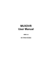
VX Series Video Recording Transmitter VX-4001 / VX-4002 VX-8002 / VX-8004 VX-16004 / VX-16008 Installation Guide Notice: Signal Communications Limited reserves the right to make improvements to the product described in this manual at any time and without notice. This manual is copyrighted. All rights are reserved. This manual may not be copied, reproduced or translated in whole or part without prior consent from Signal Communications Limited. TeleEye is a trademark of Signal Communications Limited and is registered in China, Hong Kong, US and other countries. All other trademarks are the property of their respective owners. Copyright (c) 2003 Signal Communications Limited (A member of TeleEye Group). All rights reserved. Version 1.0 Limits of Liability and Disclaimer of Warranty Signal Communications Limited has taken care in preparation of this manual, but makes no expressed or implied warranty of any kind and assume no responsibility for errors or omissions. No liability is assumed for incidental or consequential damages in connection with or arising out of the use of the information or accessories contained herein. Features and specifications are subject to change without prior notice. Table of Contents SECTION 1 INTRODUCTION • Features 1 2 SECTION 2 INSTALLATION OF TeleEye III+ VX FOR LOCAL MONITORING • Removing the Package • Front Panel Description • Rear Panel Description • Install TeleEye III+ VX for Local Video Display • Install TeleEye III+ VX with Alarm Sensors and Relay Control Port • Install TeleEye III+ VX with Telemetry Control 3 3 6 9 12 14 SECTION 3 MENU OPERATION • Menu Structure • Main Menu • Display Setup Menu • Alarm Setup Menu • Switch Setup Menu • Recording Setup Menu • Transmitter Setup Menu • Event Setup Menu • Arm/Disarm Setup Menu • Password Setup Menu 15 16 18 18 19 19 20 20 21 21 SECTION 4 INSTALL TeleEye III+ VX FOR REMOTE MONITORING 22 • Install TeleEye III+ VX for Remote Monitoring with Network A. Setup TeleEye III+ VX for connection in LAN environment 22 B. Setup TeleEye III+ VX for connection in WAN environment with static IP 25 C. Setup TeleEye III+ VX for Broadband Internet connection with dynamic IP using Internet router 26 D. Setup TeleEye III+ VX for Broadband Internet connection with dynamic IP using Broadband dialer 28 • Install TeleEye III+ VX for Remote Monitoring with ISDN/PSTN Modem 31 SECTION 5 HARD DISK INSTALLATION AND FORMATTING • Installation of Hard Disk • Hard Disk Formatting • Hard Disk Scanning • Recommended Hard Disk List 33 35 36 37 SECTION 6 USING BUILT-IN WEB SERVER • Enable the Built-In Web Server • Connecting to the Web Server 38 39 APPENDIX A sureLINK TECHNOLOGY • How to Apply for sureLINK Address 41 APPENDIX B IP ADDRESS SETUP FOR PC • IP Address Setup for Window 98/ME • IP Address Setup for Window NT/2000 • Router Configuration 45 48 49 SECTION C SPECIFICATIONS 50 Tele Eye III+ VX Installation Guide Page 1 SECTION 1 INTRODUCTION The revolutionary TeleEye III+ VX Series Video Recording Transmitter (TeleEye III+ VX) is an all-in-one video recording transmitter with dual composite video outputs and removable hard disk for standalone and remote operations. The TeleEye III+ VX supports triplex operation in which video monitoring, recording and playback can be carried out simultaneously. Recording frame rate up to 100/120 fps can be achieved. The highest recording resolution is 640x480 pixels. Recording operation can be activated by manual, scheduled and event-driven modes. The powerful TeleEye III+ VX works on broadband Internet economically and gives you exceptionally well real time video transmission at speed up to 25/30 fps. Its “sureLINK” technology allows low cost dynamic IP broadband Internet connection. Powered by its proprietary video compression technology and remote accessibility, TeleEye III+ VX provides simultaneous remote monitoring, recording and playback. Users can keep track of live video and play back recorded video from any remote locations. TeleEye III+ VX is not only designed for connectivity but a total solution for video monitoring and digital recording! Introduction Tele Eye III+ VX Installation Guide Page 2 Features z z z z z z z z z z z z z z z z z z Video recording with rate up to 100/120 fps Standalone operations Dual composite video outputs OSD menus Flexible connections – Internet, LAN, PSTN, ISDN, ADSL cable modem, mobile network, etc. Built-in web server Support static and dynamic IP Real time video transmission Up to 30fps over LAN for NTSC Up to 25fps over LAN for PAL Up to 20fps on PSTN Excellent picture resolution up to 640 x 480 pixels 4, 8, & 16 video & alarm inputs Web-based video monitoring Mobile video on Pocket PC Triplex Operation: Simultaneous video monitoring, recording & playback Video motion detection Event-driven recording Programmable video recording Auto alarm dial-back Pre- & post-alarm video recording Compatibility with popular telemetry systems Single- & multi-site monitoring Audio transmission with CAMERIO Tele EAR z z z z Video back-up function z 4 relay switches Introduction Tele Eye III+ VX Installation Guide Page 3 INSTALLATION OF TeleEye III+ VX FOR LOCAL MONITORING Removing the Package After removing the package, make sure you have the following items: - TeleEye III+ VX transmitter Software CD Hard disk cartridge (with or without hard disk) Hard disk cartridge Key x 2 AC to DC Power Adapter with cord Modem cable with 9-pin RS232 header 37-pin alarm header Warranty card Serial number and registration code card Front Panel Descriptions 4 5 6 1 2 3 1. Removable Hard Disk - All models built with a removable hard disk tray - Key lock is provided to lock the hard disk from un-authorized removing - Key is used to enable/disable the power supply to the system Installation of TeleEye III+ VX for Local Monitoring Tele Eye III+ VX Installation Guide Page 4 2. Live camera control buttons - VX–4001 / VX–4002: 1 – 4 - VX–8002 / VX–8004: 1 – 8 - VX–16004 / VX–16008: 1 – 16 - Camera control buttons allow user to fast switch to a specific camera for local monitoring - The buttons are also used for password input 3. Screen mode control / Menu control buttons Enter - There are 2 modes for these buttons, either in live mode or menu control mode - In live mode, the buttons are used to change video display mode in full screen, quad screen, full screen page mode and quad screen page mode - In menu control mode, the buttons are used as “up”, “down”, “left”, “right” and “Enter” control 4. Local Playback control buttons - These 5 buttons are used for recording playback control only - The functions are pause, fast backward, play, fast forward, and stop Installation of TeleEye III+ VX for Local Monitoring Tele Eye III+ VX Installation Guide Page 5 5. Mode control buttons Event Rec Live Play Menu - These 5 buttons are used for switching between the control modes - Event button: fast switch to event menu at any time - Rec button: enable/disable normal recording at any time - Live button: view live video at any time - Play button: fast switch to playback log menu - Menu button: switch to menu for system settings, recording settings and event settings etc. 6. Notification LEDs There are 5 notification LEDs, 3 blue color and 2 red color from right to left Event LED Recording LED Live LED Play LED Power LED Power LED: this LED will be ON when hard disk rack key is locked and power switch is turned on. This LED will blink during system initiation, and remains ON after initiation. Play LED: this LED will be ON when user press the [Play] button, it will turn OFF when the system is in live mode Live LED: this LED is ON indicating that video from the video out connectors are live videos. During recording video playback, this LED turns OFF Recording LED: this LED will turn ON when TeleEye III+ VX is doing recording Event LED: this LED will blink when event is triggered Installation of TeleEye III+ VX for Local Monitoring Tele Eye III+ VX Installation Guide Page 6 Rear Panel Descriptions 1 2 5 4 6 3 1. VIDEO INPUT Connectors - VX–4001 / VX–4002: CH1 – CH4 - VX–8002 / VX–8004: CH1 – CH8 - VX–16004 / VX–16008: CH1 – CH16 - Standard BNC connectors for color and black and white video sources - A composite video signal should be supplied to these connectors 2. VIDEO OUTPUT Connectors - VIDEO OUT1 and VIDEO OUT2 - A composite video signal with 1V p-p is output from these connectors - PAL/CCIR format with 625 lines, 50 fields per second - NTSC/EIA format with 525 lines, 60 fields per second 3. RELAY OUT / ALARM IN Port - 4 control switches are available for all models. - VX–4001 / VX–4002: 4 alarm ports - VX–8002 / VX–8004: 8 alarm ports - VX–16004 / VX–16008: 16 alarm ports Installation of TeleEye III+ VX for Local Monitoring 7 8 9 Tele Eye III+ VX Installation Guide Page 7 - All alarm ports are NC/NO type input - Alarm port 1 can be configured as arm/disarm input 4. Ethernet Socket (10/100 Base-T) - This socket is used for connecting TeleEye III+ VX to the corporate computer network (e.g. LAN) 5. Collision & Link LED Status COL LED: when on, indicates that collision is occurring on the network. LINK LED: when on, indicates that TeleEye III+ VX is connecting to the network and ready to function. 6. AUX Port - A DB-9 female connector of DCE format, capable of connecting to DTE such as remote Pan/Tilt/Zoom operation - Used for configuring the TeleEye III+ VX ’s internal settings Pin number Definition Direction 1 2 3 4 5 6 7 8 9 CD RXD TXD DTR GND DSR RTS CTS Output Output Input Input ––– Output Input Output N/A Installation of TeleEye III+ VX for Local Monitoring Tele Eye III+ VX Installation Guide Page 8 7. MODEM Port - A DB-9 male connector of DTE format, capable for connecting to DCE such as modem, ISDN terminal adaptor Pin number Definition Direction 1 2 3 4 5 6 7 8 9 CD RXD TXD DTR GND DSR RTS CTS Input Input Output Output ––– Input Output Input N/A 8. Power Jack - A 2.1mm D.C. power jack for the connection to the power supply (12V D.C.) 9. Switch - A power switch to switch on or off the TeleEye III+ VX transmitter Installation of TeleEye III+ VX for Local Monitoring Tele Eye III+ VX Installation Guide Page 9 Install TeleEye III+ VX for Local Video Display VIDEO IN connect to camera with coaxial cables with BNC header VIDEO OUT connect to coaxial video cable with BNC header TeleEye III+ VX BNC cables Video Cameras Power Adapter BNC cable DC power supply input with 12VDC, centre positive Monitor Procedures: 1. Insert the hard disk cartridge into the hard disk tray of TeleEye III+ VX 2. Using the key provided to lock the hard disk cartridge 3. Connect video cameras to input video channels with BNC cable 4. Connect the VIDEO OUT1 to a monitor using BNC cable 5. Plug the DC supply to the power jack from the power adapter 6. Switch on the TeleEye III+ VX and you will see the live video on the monitor. For the first time you use TeleEye III+ VX, the live display mode is in quad mode, which means you will see four cameras on the screen at the same time Installation of TeleEye III+ VX for Local Monitoring Tele Eye III+ VX Installation Guide Page 10 16:28:30 CAMERA 1 CAMERA 2 CAMERA 3 CA M ERA4 7. Press the [full screen mode control] button to switch to the full screen mode. You can press the [quad screen mode control] button again to switch back to quad mode Full screen mode control button 16:28:30 Quad screen mode control button CAMERA 1 Enter 8. Press the [live camera control] button to switch to a different camera 16:28:30 1 2 3 4 ... CAMERA 3 Installation of TeleEye III+ VX for Local Monitoring Tele Eye III+ VX Installation Guide Page 11 9. Press the [page switching mode control] button to view all cameras sequentially Page switching mode control (full screen) button Page switching mode control (quad screen) button Enter 16:28:35 162830 5 sec CAMERA 1 CAMERA 2 5 sec 16:28:45 16:28:40 5 sec CAMERA 4 CAMERA 3 5 sec Other Cameras Installation of TeleEye III+ VX for Local Monitoring Tele Eye III+ VX Installation Guide Page 12 Install TeleEye III+ VX with Alarm Sensors and Relay Control Port TeleEye III+ VX supports up to 16 alarm ports for connecting with alarm sensors, and 4 relay ports for remote/local controls. The definitions of alarm and relay control port are shown in the following diagram. For VX-4001/ VX-4002: Pin 1 Pin 2 Pin 3 Pin 4 Pin 5 Pin 6 Pin 7 Pin 8 Pin 9 Pin 10 Pin 11 Pin 12 Pin 13 Pin 14 Pin 15 Pin 16 Pin 17 Pin 18 Pin 19 ALARM 1 ALARM 2 ALARM 3 ALARM 4 N/C N/C N/C N/C N/C N/C N/C N/C N/C N/C RELAY 0a RELAY 1a RELAY 2a RELAY 3a N/C Pin 20 Pin 21 Pin 22 Pin 23 Pin 24 Pin 25 Pin 26 Pin 27 Pin 28 Pin 29 Pin 30 Pin 31 Pin 32 Pin 33 Pin 34 Pin 35 Pin 36 Pin 37 GND GND GND GND GND GND GND GND GND GND GND GND N/C N/C RELAY 0b RELAY 1b RELAY 2b RELAY 3b ALARM 1 ALARM 2 ALARM 3 ALARM 4 ALARM 5 ALARM 6 ALARM 7 ALARM 8 N/C Pin 20 Pin 21 Pin 22 Pin 23 Pin 24 Pin 25 Pin 26 Pin 27 Pin 28 GND GND GND GND GND GND GND GND GND For VX-8002 / VX-8004: Pin 1 Pin 2 Pin 3 Pin 4 Pin 5 Pin 6 Pin 7 Pin 8 Pin 9 Installation of TeleEye III+ VX for Local Monitoring Tele Eye III+ VX Installation Guide Pin 10 Pin 11 Pin 12 Pin 13 Pin 14 Pin 15 Pin 16 Pin 17 Pin 18 Pin 19 Page 13 N/C N/C N/C N/C N/C RELAY 0a RELAY 1a RELAY 2a RELAY 3a N/C Pin 29 Pin 30 Pin 31 Pin 32 Pin 33 Pin 34 Pin 35 Pin 36 Pin 37 GND GND GND N/C N/C RELAY 0b RELAY 1b RELAY 2b RELAY 3b ALARM 1 ALARM 2 ALARM 3 ALARM 4 ALARM 5 ALARM 6 ALARM 7 ALARM 8 ALARM 9 ALARM 10 ALARM 11 ALARM 12 ALARM 13 ALARM 15 RELAY 0a RELAY 1a RELAY 2a RELAY 3a N/C Pin 20 Pin 21 Pin 22 Pin 23 Pin 24 Pin 25 Pin 26 Pin 27 Pin 28 Pin 29 Pin 30 Pin 31 Pin 32 Pin 33 Pin 34 Pin 35 Pin 36 Pin 37 GND GND GND GND GND GND GND GND GND GND GND GND ALARM 14 ALARM 16 RELAY 0b RELAY 1b RELAY 2b RELAY 3b For VX-16004 / VX-16008: Pin 1 Pin 2 Pin 3 Pin 4 Pin 5 Pin 6 Pin 7 Pin 8 Pin 9 Pin 10 Pin 11 Pin 12 Pin 13 Pin 14 Pin 15 Pin 16 Pin 17 Pin 18 Pin 19 Installation of TeleEye III+ VX for Local Monitoring Tele Eye III+ VX Installation Guide Page 14 Install TeleEye III+ VX with Telemetry Control As TeleEye III+ VX built with a RS485 port, you can connect this port to Pan/Tilt/Zoom cameras. The connection diagram is shown below. RS485 port connect with camera Monitor BNC cable Power Adapter TeleEye III+ VX BNC cables 2 wire RS485 bus P/T/Z camera BNC cable Video Cameras Note: RS485 and RS232 AUX port are shared port in TeleEye III+ VX. Only connect to one port at a time. Connecting both ports at the same time will cause both ports malfunction. Installation of TeleEye III+ VX for Local Monitoring Tele Eye III+ VX Installation Guide Page 15 SECTION 3 MENU OPERATION Menu Structure The system setup and operation of TeleEye III+ VX is controlled through menus. The overall menu tree is shown in the following diagram. The function of each menu will be explained later in this section. [ DISPLAY SETUP ] CAMERA SETUP ... VIDEO SETUP ... OSD COLOR BLUE TIME DISPLAY TOP LEFT CAMERA NAME DISPLAY BOTTOM PAGE SWITCHING (SEC) 1 BACK [ALARM SETUP] ALARM NAME ... ALARM TYPE ... ALARM INSTALLED -2345678-------ALARM ASSOCIATE CAMERA . . . BACK [ SWITCH SETUP ] [ MAIN MENU ] DISPLAY SETUP ALARM SETUP SWITCH SETUP RECORDING SETUP TRANSMITTER SETUP EVENT SETUP ARM/DISARM SETUP PASSWORD SETUP EXIT ... ... ... ... ... ... ... ... SWITCH NAME SWITCH TYPE SWITCH ON/OFF BACK ... ... ... [ RECORDING SETUP ] DISK INFORMATION ... RECORDING MODE ... NORMAL RECORDING ... PRE-ALARM RECORDING ... PROGRAMMABLE RECORDING . . . AUDIO RECORDING ... RECORDING RESOLUTION MEDIUM RECORDING QUALITY EXCELLENT BACK [ TRANSMITTER SETUP ] GENERAL SETUP NETWORK SETUP ADV. DISK SETUP BACK Menu Operation ... ... ... Tele Eye III+ VX Installation Guide Page 16 [ EVENT SETUP] ALARM EVENT MOTION EVENT VIDEO LOSS EVENT DISK FULL EVENT SYSTEM FAILURE EVENT MOTION CAMERA SETUP EVENT SWITCH SETUP DIAL BACK SETUP EMAIL SETUP BACK ... ... ... ... ... ... ... ... ... [ ARM DISARM SETUP ] DISARM TYPE (ALARM 1) NORMAL OPEN ASSOCIATE ALARM EVENT YES ASSOCIATE MOTION EVENT YES BACK [ PASSWORD SETUP ] ENABLE SETUP MENU PASSWRD NO ENABLE PLAYBACK MENU PASSWRD NO ENABLE EVENT MENU PASSWRD NO ENABLE RECORDING MENU PASSWRD NO CHANGE PASSWORD ****** BACK Main Menu [ MAIN MENU ] DISPLAY SETUP ALARM SETUP SWITCH SETUP RECORDING SETUP TRANSMITTER SETUP EVENT SETUP ARM/DISARM SETUP PASSWORD SETUP EXIT Menu Operation ... ... ... ... ... ... ... ... Tele Eye III+ VX Installation Guide Page 17 1. Press the [Menu] button to pop up the main menu Event Rec Live Play Menu 2. Using the [up/down arrow] button to select a sub-menu Enter 3. A selected sub-menu item will be pointed by a hand cursor and highlighted 4. Press [Enter] button to confirm the selection and pop up the sub-menu 5. The main menu contains the following items DISPLAY SETUP ALARM SETUP SWITCH SETUP RECORDING SETUP TRANSMITTER SETUP EVENT SETUP PASSWORD SETUP EXIT : Change camera, live video and OSD related settings : Change alarm related settings : Change relay switch related settings : Change recording related settings : Change the transmitter general and network settings : Change event, and event related settings : Change system password settings : Exit the main menu 6. Menu item ended with [. . .] indicates sub-menu exist. You can always press the [Enter] button to pop up the sub-menu 7. If menu item not ended with [. . .] but provides selection, you can always press the [left/right arrow] button to toggle the selections Left/right arrow button to toggle selection Enter 8. In menu operation mode, the [Menu] button act as a “Back” button, you can press the [Menu] button back to previous menu Menu Operation Tele Eye III+ VX Installation Guide Page 18 Display Setup Menu [ DISPLAY SETUP ] CAMERA SETUP VIDEO SETUP OSD COLOR TIME DISPLAY CAMERA NAME DISPLAY PAGE SWITCHING (SEC) BACK ... ... BLUE TOP LEFT BOTTOM 1 The display setup menu contains the following items CAMERA SETUP VIDEO SETUP OSD COLOR TIME DISPLAY CAMERA NAME DISPLAY PAGE SWITCHING (SEC) BACK : Change camera name, camera install : Change video brightness, contrast and color format : Change OSD color : Change the position of time display on OSD : Change the position of camera name display on OSD : Change the page switching time : Back to previous menu Alarm Setup Menu [ALARM SETUP] ALARM NAME ... ALARM TYPE ... ALARM INSTALLED -2345678-------ALARM ASSOCIATE CAMERA ... BACK The alarm setup menu contains the following items ALARM NAME ALARM TYPE ALARM INSTALLED ALARM ASSOCIATE CAMERA BACK Menu Operation : Change alarm port name : Change alarm type, normal close or normal open : Change installed alarms : Change alarm associate camera for alarm recording : Back to previous menu Tele Eye III+ VX Installation Guide Page 19 Switch Setup Menu [ SWITCH SETUP ] SWITCH NAME SWITCH TYPE SWITCH ON/OFF BACK ... ... ... The switch setup menu contains the following items SWITCH NAME SWITCH TYPE SWITCH ON/OFF BACK : Change relay switch name : Change relay switch type : Manually control the switch to ON/OFF state : Back to previous menu Recording Setup Menu [ RECORDING SETUP ] DISK INFORMATION ... RECORDING MODE ... NORMAL RECORDING ... PRE-ALARM RECORDING ... PROGRAMMABLE RECORDING ... AUDIO RECORDING ... RECORDING RESOLUTION MEDIUM RECORDING QUALITY EXCELLENT BACK The recording setup menu contains the following items DISK INFORMATION : Report the hard disk information RECORDING MODE : Select the fix or cyclic recording mode NORMAL RECORDING : Change normal recording enabled cameras PRE-ALARM RECORDING : Change settings of programmable recording PROGRAMMABLE RECORDING : Enable/Disable pre-alarm recording AUDIO RECORDING : Change settings of audio recording RECORDING RESOLUTION : Change recording resolution (use left/right arrow button) RECORDING QUALITY : Change recording quality (use left/right arrow button) BACK : Back to previous menu Menu Operation Tele Eye III+ VX Installation Guide Page 20 Transmitter Setup Menu [ TRANSMITTER SETUP ] GENERAL SETUP NETWORK SETUP ADV. DISK SETUP BACK ... ... ... The transmitter setup menu contains the following items GENERAL SETUP NETWORK SETUP ADV. DISK SETUP BACK : Change general settings such as date/time, modem port : Change network type setting such as IP address, port : Hard disk scanning and formatting tools : Back to previous menu Event Setup Menu [ EVENT SETUP] ALARM EVENT MOTION EVENT VIDEO LOSS EVENT DISK FULL EVENT SYSTEM FAILURE EVENT MOTION CAMERA SETUP EVENT SWITCH SETUP DIAL BACK SETUP EMAIL SETUP BACK ... ... ... ... ... ... ... ... ... The event setup menu contains the following items ALARM EVENT MOTION EVENT VIDEO LOSS EVENT DISK FULL EVENT SYSTEM FAILURE EVENT MOTION CAMERA SETUP EVENT SWITCH SETUP DIAL BACK SETUP EMAIL SETUP BACK Menu Operation : Change alarm event associated actions : Change motion event associated actions : Change video loss event associated actions : Change disk full event associated actions : Change system failure event associated actions : Enable/Disable motion detection for a particular camera : Change relay switch type for event triggered actions : Change dial back action settings : Change Email action settings : Back to previous menu Tele Eye III+ VX Installation Guide Page 21 Arm/Disarm Setup Menu [ ARM DISARM SETUP ] DISARM TYPE (ALARM 1) NORMAL OPEN ASSOCIATE ALARM EVENT YES ASSOCIATE MOTION EVENT YES BACK The arm/disarm setup menu contains the following items DISARM TYPE (ALARM 1) ASSOCIATE ALARM EVENT ASSOCIATE MOTION EVENT BACK : Change arm/disarm type : Change arm/disarm associated with alarm event : Change arm/disarm associated with motion event : Back to previous menu Note: ARM/DISARM is controlled by alarm 1 Password Setup Menu [ PASSWORD SETUP ] ENABLE SETUP MENU PASSWRD NO ENABLE PLAYBACK MENU PASSWRD NO ENABLE EVENT MENU PASSWRD NO ENABLE RECORDING MENU PASSWRD NO CHANGE PASSWORD ****** BACK The password setup menu contains the following items ENABLE SETUP MENU PASSWORD ENABLE PLAYBACK MENU PASSWORD ENABLE EVENT MENU PASSWORD ENABLE RECORDING MENU PASSWORD CHANGE PASSWORD BACK Menu Operation : Enable or disable setup menu password : Enable or disable playback menu password : Enable or disable event menu password : Enable or disable recording menu password : Change to a new password : Back to previous menu Tele Eye III+ VX Installation Guide Page 22 SECTION 4 INSTALLATION OF TeleEye III+ VX FOR REMOTE MONITORING Install TeleEye III+ VX for Remote Monitoring with Network A. Setup TeleEye III+ VX for connection in LAN environment Before setting up the transmitter on LAN, you need to prepare the following items: - A straight through RJ45 Ethernet cable - An IP address which is unique in your LAN network. Consult your network administrator if you don’t have Procedures: 1. Follow the steps of setting up TeleEye III+ VX for local video display, now you can see the live video and OSD on the monitor 2. Press the [Menu] button on front panel of TeleEye III+ VX such that the OSD main menu will popup on the monitor as follows Event Rec Live Play [ MAIN MENU ] DISPLAY SETUP ALARM SETUP SWITCH SETUP RECORDING SETUP TRANSMITTER SETUP EVENT SETUP ARM/DISARM SETUP PASSWORD SETUP EXIT ... ... ... ... ... ... ... ... Menu • Use the arrow button to move down to select the [TRANSMITTER SETUP] menu. The selected item will be pointed by a hand icon. • Press the [Enter] button to enter the selected sub-menu Installation of Tele Eye III+ VX for Remote Monitoring Tele Eye III+ VX Installation Guide Page 23 [ TRANSMITTER SETUP ] GENERAL SETUP NETWORK SETUP ADV. DISK SETUP BACK ... ... ... [ NETWORK SETUP ] TRANSMITTER IP SURELINK PROXY SERVER GATEWAY IP BUILT-IN WEB SERVER BACK • In the [TRANSMITTER SETUP] menu, move the cursor to [NETWORK SETUP] • Press the [Enter] button to enter the selected sub-menu • If you have selected the wrong submenu, you can select the [BACK] item to go back to the previous menu • Later on you can go back to this menu to enable the built-in web server so that you can use a web browser (eg. IE) to test the connection ... ... ... 192.168.0.1 ENABLED Menu items ended with […] indicate sub-menu exist [ TRANSMITTER IP SETUP ] IP SUBNET MASK PORT BACK 192.168.0.2 255.255.255.0 1024 [ IP SETUP ] 0 5 BACK 1 6 NEXT 2 7 SPACE 3 8 CLEAR 4 9 END • Use Cursor button to move the cursor to select 0-9, [BACK], [NEXT], etc. • Use the [Enter] button to confirm selection • After entering the IP address, select [END] and press [Enter] button to go back to previous menu for subnet mask and port number setting IP: 192 . 168 . 000 . 002 3. After setting up the IP address, you need to setup the subnet mask and port number in the similar way Installation of Tele Eye III+ VX for Remote Monitoring Tele Eye III+ VX Installation Guide Page 24 4. After changing any network settings, you should back to the [MAIN MENU] and [EXIT] the main menu to save all the settings. Or you can press the [Live] button to fast exit the menu operation 5. Now connect the TeleEye III+ VX to your LAN using Ethernet cable as shown in the following diagram Ethernet port connect with RJ45 header Power Adapter TeleEye III+ VX BNC cables CAT-5 Ethernet cable 192.168.0.3 192.168.0.5 BNC cable 192.168.0.4 Video Cameras Network switch Monitor 192.168.0.2 LINK COL Ethernet 10/100 Base T 6. Power on the TeleEye III+ VX. You will notice the LINK LED is on and COL LED is off which indicate you have connected to your LAN network properly. 7. If you have enabled the built-in web server of TeleEye III+ VX, you can connect to TeleEye III+ VX using a web browser (eg. IE) on a PC inside the network. Type the address as (eg. http://192.168.0.3 ), you are prompt to enter the password (default is “000000”). Please see section 5 for detail on built-in web server access. 8. If all the settings are correct, you can view the video through the browser. Installation of Tele Eye III+ VX for Remote Monitoring Tele Eye III+ VX Installation Guide Page 25 B. Setup TeleEye III+ VX for connection in WAN environment with static IP Connection topology: The connection topology of TeleEye III+ VX in WAN environment is similar in the case of LAN. An additional equipment called Router/Gateway is needed for connecting the LAN with WAN. Therefore, we need to setup the gateway IP for TeleEye III+ VX. 192.168.0.3 TeleEye III+ VX 192.168.0.5 210.17.139.70 Router/Gateway 192.168.0.1 Network Switch Internet 192.168.0.2 192.168.0.4 Procedures: 1. Follow the steps of setting up TeleEye III+ VX for local video display so that you can configure everything with OSD. Press the button [Menu], and then by entering the menu [MAIN MENU] and [TRANSMITTER SETUP], you can see the following menu. [ NETWORK SETUP ] TRANSMITTER IP SURELINK PROXY SERVER GATEWAY IP BUILT-IN WEB SERVER BACK ... ... ... 192.168.0.1 ENABLED • Use Cursor button to select the [GATEWAY IP] item • Use the [Enter] button to enter the [GATEWAY IP] sub-menu to change the gateway IP • Exit all menus to save the settings 2. Power on the TeleEye III+ VX. The LINK LED is on and COL LED is off, which indicate that you have connected to your LAN properly. Installation of Tele Eye III+ VX for Remote Monitoring Tele Eye III+ VX Installation Guide Page 26 C. Setup TeleEye III+ VX for Broadband Internet connection with dynamic IP using Internet router Connection topology: Nowadays, Broadband Internet access is established by using ADSL modem or Cable modem. For ADSL modem, an Internet Router is used to be setup with the broadband access account name and password. To enable a remote viewer to connect to TeleEye III+ VX through the Internet, we need to setup port mapping for the Internet Router. 192.168.0.3 TeleEye III+ VX 192.168.0.5 210.177.50.156 (dynamic) Internet Router 192.168.0.1 Network Switch ADSL Modem Internet 192.168.0.2 192.168.0.4 Procedures: 1. Install ADSL modem and Internet Router as shown in the connection topology diagram. Setup the Port mapping for Internet Router so that other PCs on the Internet can “see” TeleEye III+ VX using that specific port. A typical port mapping setting is illustrated in the following diagram. Internet Router Internet 210.177.50.156 PORT 1024 Auto connection 192.168.0.3 PORT 1024 Installation of Tele Eye III+ VX for Remote Monitoring TeleEye III+ VX Tele Eye III+ VX Installation Guide External port Internal IP Internal port Page 27 1024 192.168.0.2 1024 2. The IP address assigned by the ISP to you through ADSL modem is dynamic, which means it will change after certain period of time. In order to make the TeleEye III+ VX addressable, you need to apply for our proprietary sureLINK service. Procedures involved are listed in appendix A. 3. After successful application of sureLINK service, you will obtain a sureLINK address, for example “www.your_site.your_company.teleeye.net”. 4. Follow the steps below to set the sureLINK address and DNS name into TeleEye III+ VX. [ NETWORK SETUP ] TRANSMITTER IP SURELINK PROXY SERVER GATEWAY IP BUILT-IN WEB SERVER BACK ... ... ... 192.168.0.1 ENABLED [ SURELINK SETUP ] ENABLE NO ADDRESS WW…TELEEYE… REFRESH RATE (MIN) 15 DNS SERVER 1 0.0.0.0 DNS SERVER 2 0.0.0.0 BACK • Press [Menu] button to enter the [MAIN MENU], and then select [TRANSMITTER SETUP] -> [NETWORK SETUP] • Use the arrow button to select [SURELINK] item, press [Enter] to popup the [SURELINK SETUP] menu • Select the [ENABLE] item, then use the left and right arrow button to select YES • [ADDRESS], [DNS Enter the SERVER1], [DNS SERVER2] item, and change them to the correct value • Exit all menus to save the settings 5. DNS address enables your TeleEye III+ VX using the sureLINK address to update its IP address to TeleEye’s sureLINK server, the refresh rate indicates the time duration for updating. Duration of 15-45 minutes is frequent enough. 6. After finish all configurations, power resets the TeleEye III+ VX to make the new values effective. Installation of Tele Eye III+ VX for Remote Monitoring Tele Eye III+ VX Installation Guide Page 28 7. Try to use a web browser (eg. IE) to connect to TeleEye III+ VX by entering its sureLINK address, you can see the video on browser if all your settings are correct. (Note: you must enable the built-in web server of TeleEye III+ VX before doing the testing) D. Setup TeleEye III+ VX for Broadband Internet connection with dynamic IP using Broadband dialer Connection topology: It is possible to share the Broadband Internet access without an Internet router. Instead, a dedicated PC is required to control the ADSL modem to connect to the Internet. This dedicated PC will obtain a “real” but dynamic IP from the ISP, a proxy server is thus required to act as a gateway between TeleEye III+ VX and the Internet. 192.168.0.3 TeleEye III+ VX 192.168.0.5 ADSL Modem Network Switch Internet 192.168.0.4 PC with Broadband dialer for Internet access and TeleEye proxy server for VX Fixed virtual IP: 192.168.0.2 Dynamic real IP: 210.177.50.156 The video data flow between TeleEye III+ VX to the Internet through the proxy server is illustrated in the following diagram. Installation of Tele Eye III+ VX for Remote Monitoring Tele Eye III+ VX Installation Guide Page 29 Data Data TeleEye Proxy Server Data ADSL Modem Broadband dial-up to Internet To WAN (Dynamic IP) TeleEye III+ VX Transmitter installation procedures: 1. Install ADSL modem as shown in the connection topology diagram. Connect TeleEye III+ VX to network switch, and following the steps in setting up TeleEye III+ VX for Broadband Internet connection with dynamic IP using Internet router. Notice that the gateway of TeleEye III+ VX should remain blank in this case. 2. Press [Enter] button to pop up the main menu, and enter the sub-menu [TRANSMIITER SETUP] -> [NETWORK SETUP]. [ NETWORK SETUP ] TRANSMITTER IP SURELINK PROXY SERVER GATEWAY IP BUILT-IN WEB SERVER BACK ... ... ... 192.168.0.1 ENABLED 3. Select [PROXY SERVER] item and then press enter to edit the proxy sever IP address. [ PROXY SERVER SETUP ] ENABLE IP PORT BACK NO 0.0.0.0 0 4. You need to set edit each items of the [PROXY SERVER SETUP] menu. Select [ENABLE] item and user left/right arrow button to toggle select [YES], enter the IP address (eg. 192.168.0.2 as in the connection topology), and set the port number (default value is 19001). Installation of Tele Eye III+ VX for Remote Monitoring Tele Eye III+ VX Installation Guide Page 30 5. Setup sureLINK address and related settings as previous discussed. 6. Reset TeleEye III+ VX so that all settings will take effect. PC software installation procedures: 1. On PC side, you need to install the Broadband dialer software and TeleEye proxy server software. 2. For Broadband dialer, consult your Broadband dialer software installation manual. 3. Install TeleEye proxy server software, which is bundled with TeleEye III+ WRS3-AD software. 4. Start TeleEye proxy server, the following screen will pop up. Enter the transmitter IP (eg. 192.168.0.3) and port number (eg. 1024). The external port is the port number of the dynamic real IP, which is used for other PCs on the Internet to access the transmitter. 5. Click the [Add] button, so that the configurations will take effect and saved. 6. Try to connect to the TeleEye III+ VX on the Internet with web browser using its sureLINK address. Installation of Tele Eye III+ VX for Remote Monitoring Tele Eye III+ VX Installation Guide Page 31 Install TeleEye III+ VX for Remote Monitoring with ISDN/PSTN Modem Modem port connect to a DB-9 connector Power Adapter BNC cables RS232 serial cable BNC cable ISDN/PSTN ISDN/PSTN modem Video Cameras netw ork Monitor Procedures: 1. Follow the steps of setting up TeleEye III+ VX for local video display, so that you can configure the modem port locally with keypad and monitor 2. Press the [Menu] button, and then [TRANSMITTER SETUP], you will enter the following menu [ TRANSMITTER SETUP ] GENERAL SETUP NETWORK SETUP ADV. DISK SETUP BACK ... ... ... 3. Select the [GENERAL SETUP] item, the general setup menu will popup below, select [RS232 SETUP] item, and press [Enter] button to enter the sub-menu. Installation of Tele Eye III+ VX for Remote Monitoring Tele Eye III+ VX Installation Guide Page 32 • [ GENERAL SETUP ] Use [Enter] button to enter the selected sub-menu DATE/TIME SETUP 30/05/03 20:20:52 RS232 SETUP ... THROUGHPUT CONTROL (BPS) 1M REGISTRATION CHECKING NO VIDEO MODE QUALITY BACK [ RS232 PORT SETUP ] MODEM PORT BIT RATE BACK 38400 Modem port bit rate is the maximum bit rate between TeleEye III+ VX and the modem, the actual transmission bit rate may depends on the bit rate between the modems after training 4. Connect an ISDN/PSTN modem to TeleEye III+ VX using RS232 serial cable. Power on both TeleEye III+ VX and modem, using the TeleEye WRS3-AD software to make a modem connection to TeleEye III+ VX transmitter. If all the configurations are correct, you will see video on the WRS3-AD software. (For using of WRS3-AD software, please refer to TeleEye WRS3-AD user manual) Installation of Tele Eye III+ VX for Remote Monitoring Tele Eye III+ VX Installation Guide Page 33 SECTION 5 HARD DISK INSTALLATION AND FORMATTING Installation of Hard Disk If you want to change the hard disk of TeleEye III+ VX, you need to do the hard disk installation procedure. TeleEye III+ VX support ATA standard hard disk, it is highly recommended that you use the hard disk listed at the end of this section. Procedures: 1. Remove the hard disk rack as illustrated in the following diagram Step 3 Step 2 Step 1 Eject Hard Disk 2. Open the cover of the hard disk cartridge provided by TeleEye, you will see a power cable and a 80-pin IDE cable 3. Plug the power cable and the 80-pin IDE cable to the hard disk, and insert the hard disk into the rack 4. Fix the position of hard disk on the rack by fasten the screws 5. Cover the hard disk rack, and insert the hard disk into TeleEye III+ VX 6. Lock the Key Lock. Configure the TeleEye III+ VX with local display as described in previous sections, and then switch the power on Hard Disk Installation and Formatting Tele Eye III+ VX Installation Guide Page 34 Step 2 Step 1 Step 3 Insert Hard Disk 7. Press the [Menu] button to pop up the [MAIN MENU] on the screen. Select [TRANSMITTER SETUP] and press [Enter] button, the following menu will be shown [ TRANSMITTER SETUP ] GENEARAL SETUP NETWORK SETUP ADV. DISK SETUP BACK 8. ... ... ... Select [ADV. DISK SETUP] using the up/down arrow button and the press [Enter] button to enter the sub-menu as follows [ TRANSMITTER SETUP ] GENEARAL SETUP NETWORK SETUP ADV. DISK SETUP BACK 9. ... ... ... Select [DISK INFORMATION] item, and press [Enter] button, you will get the hard disk information as follows [ DISK INFORMATION ] DISK CAPACITY (GB) AVAILABLE SPACE USED SPACE BACK 80.03 96% 4% 10. If you installed the hard disk properly, the item [DISK CAPACITY] should match with the capacity specification of the hard disk roughly Hard Disk Installation and Formatting Tele Eye III+ VX Installation Guide Page 35 Hard Disk Formatting Hard disk formatting will reconstruct the structure of hard disk so that it is readable by TeleEye III+ VX. If you have your own hard disk to install to TeleEye III+ VX, you must perform hard disk formatting. It will be used in the following cases: 1. A new hard disk you just brought 2. No recorded video can be played 3. You want to format the hard disk so as to have a clean recording space, redeem the file allocation. Procedures: 1. Press the [Menu] button to pop up the [MAIN MENU] on the screen. Select [TRANSMITTER SETUP] -> [ADV. DISK SETUP], and press the [Enter] button to pop up the following sub-menu [ ADV. DISK SETUP ] DISK INFORMATION FORMAT DISK SCAN DISK BACK 2. ... ... ... Select the [FORMAT DISK] item, and press [Enter] button to confirm the selection. A message box will pop up as follow [ MESSAGE ] ALL DATA WILL BE ERASED, ARE YOU SURE ? YES 4. NO Use left/right arrow button to select [YES] and press [Enter] button, the system will start formatting. The following information will show on OSD. [ ADV. DISK SETUP ] FORMATTING… CANCEL Hard Disk Installation and Formatting 20% Tele Eye III+ VX Installation Guide Page 36 Note: Having confirmed the hard disk formatting, all your data on the hard disk will be lost. 5. Upon completion of hard disk formatting, the following message box will pop up [ ADV. DISK SETUP ] FORMAT COMPLETED BACK 100% Hard Disk Scanning It has similar function to the SCAN DISK provided by the Operating System of your personal computer. It is easy to understand why and when you will use it. Our TeleEye III+ VX provides this function so as to rescue the hard disk when errors found, and to enhance its performance and reliability. After scanning, the damaged files will be deleted so that the remaining normal videos can be seen. It will be used in the following cases: 1. You cannot playback the recorded videos 2. You cannot search the desired video from the recording log. Or although you can find it, you cannot play it 3. You wonder if the hard disk has problem Procedures: 1. Press the [Menu] button to pop up the [MAIN MENU] on the screen. Select [TRANSMITTER SETUP] -> [ADV. DISK SETUP], and then press the [Enter] button to pop up the following sub-menu [ ADV. DISK SETUP ] DISK INFORMATION FORMAT DISK SCAN DISK BACK 2. ... ... ... Select the [SCAN DISK] item, and press [Enter] button to confirm the selection. A message box will pop up as follow Hard Disk Installation and Formatting Tele Eye III+ VX Installation Guide Page 37 [ MESSAGE ] START TO SCAN HARD DISK, ARE YOU SURE ? YES 3. NO Use left/right arrow button to select [YES] and press [Enter] button, the system will start scanning. The following information will be shown on OSD [ ADV. DISK SETUP ] CHECKING FOR ERRORS… CANCEL 4. 40% Upon completion of hard disk scanning, the following message box will pop up [ ADV. DISK SETUP ] CHECKING FOR ERRORS… BACK 100% Recommended Hard Disk List Product Line Hard Disk Capacity 20GB Maxtor FireBall 3 (5400 RPM) Maxtor DiamondMax Plus 8 (7200 RPM) Western Digital Protégé Value (5400 RPM) Model No. 2F020J0 6E020L0 WD200EB 40GB Maxtor FireBall 3 (5400 RPM) Maxtor DiamondMax Plus 8 (7200 RPM) Western Digital Caviar High-Performance (7200 RPM) Western Digital Protégé Value (5400 RPM) 2F040J0 6E040L0 WD400BB WD400EB 80GB Maxtor DiamondMax Plus 9 (7200 RPM) Maxtor DiamondMax 16 (5400 RPM) Western Digital Caviar Mainstream (5400 RPM) 6Y080L0 4R080L0 WD800AB 160GB Maxtor DiamondMax Plus 9 (7200 RPM) Maxtor DiamondMax 16 (5400 RPM) 6Y160P0 4A160J0 Hard Disk Installation and Formatting Tele Eye III+ VX Installation Guide Page 38 SECTION 6 USING BUILT-IN WEB SERVER Enable the Built-In Web Server PC recommendations: 128MB RAM Netscape 6.1 or Internet Explorer 5.5 or above Any OS platform with web browser and Java Support Before using the web service, you have to enable the Built-in Web Server feature. Follow the steps below to configure TeleEye III+ VX for using web feature. Procedures: 1. Press the [Menu] button to pop up the [MAIN MENU] on the screen. Select [TRANSMITTER SETUP] and press [Enter] button to pop up the following sub-menu [ TRANSMITTER SETUP ] GENERAL SETUP NETWORK SETUP ADV. DISK SETUP BACK 2. ... ... ... Select the [NETWORK SETUP] item, press [Enter] button to confirm the selection [ NETWORK SETUP ] TRANSMITTER IP SURELINK PROXY SERVER GATEWAY IP BUILT-IN WEB SERVER BACK 3. ... ... ... 192.168.0.1 ENABLED Use up/down arrow button to select the [BUILT-IN WEB SERVER] item, and use left/right arrow button to select [ENABLED]. Now the built-in web server is enabled Using Built-In Web Server Tele Eye III+ VX Installation Guide Page 39 Connecting to the Web Server sureLINK address of your transmitter, In your browser, type the eg.http://www.hkpublic.teleeye.teleeye.net or simply IP address of the transmitter, you will see a web site like: Your transmitter sureLINK address or IP address Enter the transmitter’s admin / user password to login Enter your transmitter login password and press Enter button. A new page will be displayed. Using Built-In Web Server Tele Eye III+ VX Installation Guide Page 40 You can choose the cameras by clicking the buttons on the left. Note: If you have any problem on opening the page, please go to http://java.sun.com/getjava/download.html to update your Java VM. Using Built-In Web Server Tele Eye III+ VX Installation Guide Page 41 APPENDIX A sureLINK TECHNOLOGY sureLINK technology is available in TeleEye III+ VX, which enables you to connect to the transmitter with broadband dynamic IP connection. If you can only use broadband dialup account to connect to the Internet through your computer, sureLINK provides a solution for sharing the Internet connection between your computer and the transmitter. sureLINK is a group of additional functions, services and software provided for the transmitter so as to make it connect to the Internet in any connection methods. Such function can only be used if you have applied for this service. After you have done so, you also need to configure the transmitter to make sureLINK available. This section will help you to configure and use it. By using of sureLINK technology, the powerful TeleEye III+ VX can work on broadband Internet economically, a cost effective and convenient remote live video monitoring anytime and anywhere. z sureLINK Address You can apply for a sureLINK address (domain name), such as www.hkpublic.teleeye.teleeye.net, for your transmitter. You can use this name to login or browse the built-in web server. One of the advantages is that you are not required to memorize the IP address (e.g. 210.177.50.156) of the transmitter. Since the sureLINK address is fixed while the IP address may change periodically (in case when dynamic IP is used), you do not need to worry about the expiration of the IP address. The sureLINK address can also be used in transmitter web browsing to see live video on standard web browser (e.g. IE, Netscape), it will be discussed in Section 6. z Refreshing Rate When sureLINK address feature is enabled, the transmitter will periodically update its current IP address to our database to ensure that the sureLINK address is always forwarded to a valid IP. You can set this update period at the using OSD z DNS Services: Assigned when the transmitter can directly access the Internet without the help of TeleEye Proxy Server sureLINK Technology Tele Eye III+ VX Installation Guide Page 42 How to Apply for sureLINK Address You can apply for sureLINK by visiting our web site at http://www.TeleEye.com 2 1 Step1: Sign up to create your user account Step 2: Login the page using your registered name and password. Step 3: Click sureLINK Address Registration button 3 sureLINK Technology Tele Eye III+ VX Installation Guide Page 43 4 Step 4: Enter a sureLINK address (Domain Name), your Transmitter Serial No. and Registration Code in the fields provided respectively. Then click the Apply button. The process is then completed. After we received your domain name registration for your transmitter, your application will be processed. Normally, it requires about 2 to 3 working days to activate sureLINK for your transmitter. You will receive a notification mail when your sureLINK service is ready. Transmitter Modification Since the sureLINK (Domain name) address corresponds to a single transmitter, if you change from one transmitter to another one, you have to inform us to update our database record. To do this, you can visit our TeleEye Product Support again and follow the steps below: Step 1: Transmitter Modification > Select a sureLINK address (Domain Name) you want to modify 1 sureLINK Technology Tele Eye III+ VX Installation Guide Page 44 2 Step 2: Enter the Old Registration Code, New Transmitter Serial Number and New Registration Code at each field provided. Click Modify button to submit the form. 4 3 If the above procedure is completed successfully, the sureLINK will be effective immediately. sureLINK Technology Tele Eye III+ VX Installation Guide Page 45 APPENDIX B IP ADDRESS SETUP FOR PC IP Address Setup for Windows 98/ME The follow procedures will set your Ethernet Card IP address manually for your local LAN purpose. Note that these procedures will NOT affect your PC to get on the Internet. If you discover that you cannot be able to access on the Internet after applying the settings, you have to undo the settings or re-install the software provided by your ISP and retry the steps again. Step 1: In Windows 98/ME desktop, select Start > Settings > Control Panel Step 2: Double click Network > Configuration, you will find that there are at least 2 fields (usually 3 fields) started with “TCP/IP ->”. 3. TCP/IP Your Ethernet card name IP Address Setup For PC Tele Eye III+ VX Installation Guide Page 46 Two of them are very important for setup. One of them is used for your local Intranet (the field may contain the name of your Ethernet card), the other one is used for your broadband Internet connection. An example is shown in the following figure. TCP/IP-> HP EN1207D-TX PCI 10/100 Fast Used for Intranet (local network) Ethernet Adapter TCP/IP-> Network TeleSystems P.P.P.o.E Broadband Internet Access (Point-to-Point Adapter Protocol over Ethernet) Note that the name of these two TCP/IP adapters may be different on your computer. You have to identify the purpose of each corresponding adapter. Step 3: Choose TCP/IP->[Your Ethernet card name] > Click Properties > IP address, enter an IP address “192.168.0.3” and subnet mask “255.255.255.0” Step 4: Click OK and OK and reboot the computer. Step 5: After booting, ensure that the computer can still be connected to the Internet. Step 6: You have to confirm that IP address has been set on your computer. On your windows, click start > run, type “winipcfg” at Open field and press OK button, then you will see a IP Configuration program shown as figure. IP Address Setup For PC Tele Eye III+ VX Installation Guide Page 47 Step 7: Select your Ethernet card name on the field, you will see an IP address on the field. Ensure that that is the same as you have set before (i.e. 192.168.0.3). If it is not so, please repeat step 12. Click OK to close the program. IP Address Setup For PC Tele Eye III+ VX Installation Guide Page 48 IP Address Setup for Windows NT/2000 The follow procedures will set your Ethernet Card IP address manually for your local LAN purpose. Note that these procedures will NOT affect your PC’s connection to the Internet. If you discover that you cannot be able to access to the Internet after applying the settings, you have to undo the settings or re-install the software provided by your ISP and retry the steps again. Step 1: In Windows NT/2000 desktop, select Start > Settings > Control Panel Step 2: Double click Network and Dial-up Connections > right click Local Area Connections and choose Properties. Step 3: Choose Internet Protocol (TCP/IP) and click Properties Your Ethernet card name IP Address Setup For PC Tele Eye III+ VX Installation Guide Page 49 Step 4: Enter an IP address, subnet mask and Default gateway. Step 5: Enter the Preferred and Alternate DNS server, if necessary. Step 6: Click OK to activate the new IP. Step 7: You have to confirm that IP address has been correctly set on your computer. On your windows, click start > run, type “cmd” at Open field and press OK button, then type “ipconfig” on the DOS prompt, you will see an IP set on your computer. Router Configuration Port Mapping in your Router For PLANET Internet SOHO Router XRTXRT-101 / XRTXRT-711, please refer to its menu 6.1 Advanced Internet Features -> Virtual Servers (Define servers on your LAN, so Internet users can access them)-> E.3 User-defined Virtual Servers Suggested Data for router: Name TeleEye IP Address 192.168.0.2 (Your transmitter IP address) Protocol TCP Internal Port No. 1024 External Port No. 1024 IP Address Setup For PC Tele Eye III+ VX Installation Guide Page 50 APPENDIX C SPECIFICATIONS MODEL STANDARD NO. OF CHANNELS RESOLUTION STANDARD NO. OF CHANNELS TYPE NETWORK CONCURRENT USERS WEB SERVER sureLINK MODEM PORT AUX PORT VX-4001 VX-4002 VX-8002 VX-8004 VX-16004 VX-16008 VIDEO INPUT (P): PAL/CCIR, 625 lines, 50 fields per second (N): NTSC/EIA, 525 lines, 60 fields per second composite video, 1 Vp-p, BNC 4 8 16 Quality mode: 640X480, 320X240, 160X120 pixels Speed mode: 512x384, 256x192, 128x96 pixels VIDEO OUTPUT (P): PAL/CCIR, 625 lines, 50 fields per second (N): NTSC/EIA, 525 lines, 60 fields per second composite video, 1 Vp-p, BNC 2 STANDALONE OPERATION System configuration, operation, audit trai COMMUNICATION RJ-45, 10/100Base-T Ethernet (auto-sensing) 6 10 18 built-in web server support Internet connection assigned with dynamic IP address RS-232C: DB-9 male, asynchronous, 8 data bits, 1 stop bit, no parity, 9.6k-115.2kbps, hardware flow control RS-232C or RS-422/485 RS-232C: DB-9 female, asynchronous, 8 data bits, 1 stop bit, no parity, 2.4k-19.2kbps, hardware flow control RS-422/485: 2-way terminal, asynchronous, 5-8 data bits, 1-2 stop bits, no/odd/even parity, 2.4k-19.2kbps RECORDING manual, programmable, event-driven IDE interface, removable 40GB, 80GB, 160GB selectable MODE HD TYPE HD SIZE MAX. RECORDING RATE# 12.5/15fps 25/30fps 25/30fps 50/60fps 50/60fps 100/120fps EVENT HANDLING external alarm, video motion detection, EVENT TYPE video loss, recording full, system failure buzzer, dial back, local recording, relay control, email notification ACTION TYPE 8x, or 7x + 16x, or 15x + 4x, or 3x + EXTERNAL INPUTS arm/disarm, NC/NO arm/disarm, NC/NO arm/disarm, NC/NO RELAY SWITCH 4 NO. OF CHANNELS 24V AC, 1000mA MAX. RATING Specifications Tele Eye III+ VX Installation Guide Page 51 POWER VOLTAGE MAX. RATING AMBIENT TEMPERATURE RELATIVE HUMIDITY DIMENSION WEIGHT Specifications 12V DC 40W 44W OPERATING ENVIRONMENT 5oC – 50oC <85% (no condensation) MECHANICAL DESIGN 360x345x95 (mmxmmxmm) 5.1 kg 5.5 kg 51W 6.3 kg