1
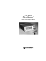
User Manual
WaveMaster™
Laser Wavelength Meter
User Manual
WaveMaster
Laser Wavelength Meter
7470 SW Bridgeport Rd.
Portland, OR 97224
WaveMaster User Manual
This document is copyrighted with all rights reserved. Under
the copyright laws, this document may not be copied in whole
or in part or reproduced in any other media without the
express written permission of Coherent, Inc. Permitted copies
must carry the same proprietary and copyright notices as were
affixed to the original. This exception does not allow copies to
be made for others, whether or not sold, but all the material
purchased may be sold, given or loaned to another person.
Under the law, copying includes translation into another
language.
Coherent and the Coherent Logo are registered trademarks of
Coherent, Inc. WaveMaster is a trademark of Coherent, Inc.
Every effort has been made to ensure that the data given in
this document is accurate. The information, figures, tables,
specifications and schematics contained herein are subject to
change without notice. Coherent makes no warranty or
representation, either expressed or implied with respect to this
document. In no event will Coherent be liable for any direct,
indirect, special, incidental or consequential damages
resulting from any defects in its documentation.
Technical Support
In the U.S.:
Should you experience difficulties with your product, or need
technical
information,
please
visit
our
website:
www.Coherent.com. You can obtain additional support by
either telephoning our Technical Support Hotline at
1.800.343.4912, or e-mailing our Support Team at
[email protected]. Telephone coverage is
available Monday through Friday (except U.S. holidays).
If you call outside our office hours, your call will be taken by
our answering system and will be returned when the office
reopens.
If there are technical difficulties with your product that cannot
be resolved by support mechanisms outlined above, please
e-mail or telephone Coherent Technical Support with a
ii
description of the problem and the corrective steps attempted.
When communicating with our Technical Support
Department, via the web or telephone, the model and serial
number of the product will be required by the Support
Engineer responding to your request.
Outside the U.S.:
If you are located outside the U.S., visit our website for
technical assistance, or telephone our local Service
Representative. Representative phone numbers and
addresses can be found on the Coherent website:
www.Coherent.com.
Coherent provides web and telephone technical assistance as
a service to its customers and assumes no liability thereby for
any injury or damage that may occur contemporaneous with
such services. These support services do not, under any
circumstances, affect the terms of any warranty agreement
between Coherent and the buyer. Operating a Coherent
product with any of its interlocks defeated is always at the
operator's risk.
iii
WaveMaster User Manual
iv
Table of Contents
TABLE OF CONTENTS
Preface .......................................................................................................... ix
U.S. Export Control Laws Compliance ........................................................ ix
Publication Updates ...................................................................................... ix
Symbols Used in This Document ...................................................................x
Safety ...................................................................................................................1
Declaration of Conformity..............................................................................3
Description .......................................................................................................5
Unpacking .......................................................................................................6
System Description .........................................................................................8
Display Unit ...........................................................................................8
Front Panel Controls .....................................................................8
Front Panel Display ....................................................................11
Rear Panel ...................................................................................14
Sensor...................................................................................................15
Power Supply .......................................................................................17
Maintenance..................................................................................................18
Replacement Parts.........................................................................................19
Operation ........................................................................................................21
Making a Measurement ................................................................................21
Remote Operation .........................................................................................24
Introduction..........................................................................................24
RS-232 Hardware Connection .............................................................25
GPIB Hardware Parameters.................................................................26
Commands Overview ..........................................................................28
IEEE 488.2 Commands When Using RS-232 .....................................29
Event Status Enable and Event Status Register ..........................30
Status Byte ..................................................................................31
v
WaveMaster User Manual
Service Request Enable Register ................................................31
IDN Fields...................................................................................32
Self-Test Codes ...........................................................................32
IEEE 488.2 Commands When Using GPIB ........................................33
User Commands...................................................................................34
Parameter Setting Commands.....................................................34
Query Commands .......................................................................35
VAL$ Format ..............................................................................36
Error Formats .......................................................................................36
GPIB Software Protocol ......................................................................38
Getting the Best from WaveMaster...............................................................39
Frequently Asked Questions ...............................................................41
Calibration and Warranty ...................................................................45
Calibration ....................................................................................................45
Coherent Calibration Facilities and Capabilities ..........................................46
Limited Warranty ..........................................................................................47
Extended Lifetime Warranty.........................................................................47
Warranty Limitations ....................................................................................48
Obtaining Service .........................................................................................49
Product Shipping Instructions.......................................................................51
Appendix A: Installing a GPIB Interface Module ................53
Appendix B: Specifications ..................................................................55
vi
Table of Contents
LIST OF TABLES
1.
2.
3.
4.
5.
6.
7.
8.
9.
10.
11.
12.
13.
14.
15.
16.
17.
18.
19.
Front Panel Display Numbers Format .......................................................11
Replacement Parts......................................................................................19
9-Pin Socket Pinout ...................................................................................25
Serial Line Communication Parameters ....................................................26
GPIB Controller Parameters ......................................................................27
IEEE 488.2 Commands When Using RS-232 ...........................................29
Event Status Enable and Event Status Register .........................................30
Status Byte .................................................................................................31
Service Request Enable Register ...............................................................31
IDN Fields..................................................................................................32
Self-Test Codes ..........................................................................................32
IEEE 488.2 Commands When Using GPIB ..............................................33
Parameter Setting Command .....................................................................34
Query Commands ......................................................................................35
VAL$ Format .............................................................................................36
Error Codes ................................................................................................37
Frequently Asked Questions ......................................................................41
Coherent Service Centers...........................................................................50
Specifications.............................................................................................55
LIST OF FIGURES
1.
2.
3.
4.
5.
Front Panel ...................................................................................................8
Rear Panel ..................................................................................................14
Exploded and Sectioned View of Laser Input Sensor Front End...............16
Setting the DIP Switch...............................................................................28
GPIB Software Protocol Example .............................................................38
vii
WaveMaster User Manual
viii
Preface
Preface
This manual contains user information for the WaveMaster™ laser wavelength meter.
U.S. Export
Control Laws
Compliance
It is the policy of Coherent to comply strictly with U.S.
export control laws.
Export and re-export of lasers manufactured by Coherent
are subject to U.S. Export Administration Regulations,
which are administered by the Commerce Department.
In addition, shipments of certain components are regulated by the State Department under the International
Traffic in Arms Regulations.
The applicable restrictions vary depending on the
specific product involved and its destination. In some
cases, U.S. law requires that U.S. Government approval
be obtained prior to resale, export or re-export of certain
articles. When there is uncertainty about the obligations
imposed by U.S. law, clarification should be obtained
from Coherent or an appropriate U.S. Government
agency.
Publication
Updates
To view information that may have been added or
changed since this publication went to print, connect to
www.Coherent.com.
ix
WaveMaster User Manual
Symbols Used
in This
Document
This symbol is intended to alert the operator to the
presence of exposure to hazardous visible and invisible laser radiation.
This symbol is intended to alert the operator to the
presence of dangerous voltages associated with the
product that may be of sufficient magnitude to constitute a risk of electrical shock.
This symbol is intended to alert the operator to the
danger of Electrostatic Discharge (ESD) susceptibility.
This symbol is intended to alert the operator to the
presence of important operating and maintenance
instructions.
x
Safety
SAFETY
Carefully review the following safety information to
avoid personal injury and to prevent damage to this
instrument or any sensor connected to it. WaveMaster
contains no user-serviceable parts. For service information, refer to “Obtaining Service” on page 49.
The use and measuring of lasers is potentially
dangerous. This instrument operates over wavelengths that include non-visible laser emissions.
Proper laser operating practice in accordance with manufacturer recommendations is vital.
Eyewear and other personal protective equipment must
be used in accordance with applicable laws and regulations.
If in doubt of correct operating procedures, consult the
laser manufacturer and your laser safety officer.
The equipment is not for use in critical medical environments.
Use only the power cord specified for the meter. The
grounding conductor of the cord must be connected
to earth ground.
1
WaveMaster User Manual
Do not operate the meter if its panels are removed or
any of the interior circuitry is exposed.
Do not operate the meter in wet or damp conditions,
or in an explosive atmosphere.
Operate the meter only within the specified voltage
range.
Do not apply a voltage outside the specified range of
the input connections.
Do not operate the meter if there are suspected failures. Refer damaged units to qualified Coherent
service personnel.
2
Safety
Declaration
of Conformity
3
WaveMaster User Manual
4
Description
DESCRIPTION
WaveMaster™ provides a simple and quick method of
determining the wavelength of lasers in the 380 to 1095
nm range, to an accuracy of 0.005 nm or better. It can
measure CW, pulsed, and single shot lasers. There are
four available units of measurement:
•
Wavelength in air (nm, at standard temperature and
pressure)
•
Wavelength in vacuum (nm)
•
Wave number in vacuum (cm-1)
•
Frequency (GHz)
WaveMaster has an internal calibration system based on
precisely known wavelengths of neon spectral lines.
Periodic recalibration is performed automatically to
ensure measurement accuracy.
Laser input to the instrument is by means of a standard
ST type fiber optic connector, which means that WaveMaster can be situated in any convenient position and
does not require alignment with the laser source.
An input sensor with a 2-meter fiber cable is supplied for
capturing or sampling of the beam, but other inputs
having a suitable connector may be provided by the user.
The maximum input to this front panel connector should
be limited to 100 mW so as to avoid internal damage.
5
WaveMaster User Manual
A front panel intensity meter assists in aligning the
sensor and in establishing a suitable signal strength level
for measurement, which can be adjusted by means of the
built in front panel attenuator.
The measured value is displayed in large, easily read
characters on a LCD panel, which also carries information on the status of the instrument. The display contrast
may be set by the user to suit the ambient conditions and
back lighting is available as required.
Remote operation is accommodated by means of an
RS-232 serial port or the optional GPIB port (available
either factory-fitted or as a user-fitted upgrade).
Specifications for WaveMaster are given on page 55.
Unpacking
WaveMaster contains accurately aligned optical
components and should not be subjected to severe
shocks, such as those generated when dropped. The
supplied shipping carton is recommended for use
whenever the instrument is transported.
The shipping carton should be inspected for any visible
damage. Check that the carton contains:
1.
This manual
2.
The WaveMaster instrument
6
Description
3.
A further carton containing:
•
WaveMaster mains power supply plus three
adapter plugs
•
Mounting base
•
Mounting post (½-inch dia. x 75 mm)
•
Post holder (3 inch, ¼ x 20)
•
WaveMaster sensor
Inspect each of the following items for damage as they
are removed from the cartons.
1.
This manual
2.
The WaveMaster instrument
3.
The WaveMaster sensor, post, holder, and stand
4.
The power supply
The desiccant packed with the instrument should be
discarded.
Advise Coherent Inc. of any shortages or damage immediately (refer to “Obtaining Service” on page 49). A
Returned Material Authorization (RMA) will be issued
for any damaged instruments (refer to “Product Shipping
Instructions” on page 51).
7
WaveMaster User Manual
System
Description
The WaveMaster equipment consists of three units:
•
The display unit
•
The sensor
•
The power supply
Display Unit
Front Panel
Controls
Figure 1. Front Panel
Here is a description of the various controls and displays:
ON/OFF: Pressing this button toggles the power to the
instrument. When switching ON, the yellow Pulse
Received indicator will light and stay lit until characters
appear on the display. This takes a few seconds. When
8
Description
switching OFF, the message “Powering Off” appears on
the display for a few seconds while the instrument shuts
down.
BACKLIGHT: Pressing this button toggles the display
back light and meter lamp ON and OFF.
CONTRAST:
These two buttons allow the user to
set a display contrast level appropriate to the ambient
lighting conditions. Holding the button down causes the
contrast to change continuously (between limits).
AUTOCAL: Pressing this button toggles the internal
automatic calibration process on and off. The current
state is shown in the Autocal box on the display above
the button. In normal circumstances AUTOCAL should
be left ON to ensure measurement accuracy. Turning
AUTOCAL off and then on forces an immediate internal
calibration.
UNITS: Pressing this button cycles through the four
available units of nm air, nm vacuum, wavenumber
(cm-1), and frequency (GHz). The current unit selected is
shown to the right of the measured value on the display.
MODE: Pressing this button cycles through the three
modes of CW, CW Av and Pulse. The mode in use is
displayed in the 'Mode' box on the display above the
button.
PULSE RECEIVED: Apart from being lit during power
up (refer to “ON/OFF” on page 8), this indicator is only
active when the instrument is in pulse mode. In Pulse
Received mode, it flashes every time a valid pulse
measurement is made.
9
WaveMaster User Manual
INPUT: This is a combined fiber optic input connector
and attenuator. The connector accepts the fiber optic
cable that is part of the sensor assembly. Turning the
attenuator clockwise (+) increases the signal delivered to
the instrument, and turning the attenuator counterclockwise (-) decreases the signal.
The connector is of the ST type and only cables terminated with this type of coupling must be used.
Attempts to use other connectors may cause damage.
Additionally, to avoid internal damage, the maximum
input power to the instrument front panel attenuator
must not exceed 100 mW.
INTENSITY: This indicates the signal strength as seen
by the instrument on a meter scale with red and green
zones.
It is not a measurement of laser power.
The sensor and input attenuator should be adjusted so
that the meter needle is in the green scale area and preferably towards the right hand side. The red region to the
right of the scale indicates danger of signal overload. The
red region to the left of the scale indicates too low a
signal, although a valid reading may still be displayed.
10
Description
Front Panel Display
The LCD presents all the information about the measurement and operation status of the instrument. Contrast can
be controlled between limits to suit the ambient lighting
conditions. Additionally, it can be backlit, together with
the intensity meter, to further improve visibility.
The upper part of the screen is used principally for the
display of measurements in the selected units, with a
blank display indicating that no valid reading is available
or possible. The selected unit is indicated to the right of
the numerical part of the display. The number format is
shown in Table 1.
Table 1. Front Panel Display Numbers Format
UNITS
DIGITS BEFORE
DECIMAL PLACE
DIGITS AFTER
DECIMAL PLACE
DISPLAY
nanometers air
up to 4
3
nm air
nanometers vacuum
up to 4
3
nm vac
wavenumber
5
2
cm-1
frequency
6
1
GHz
In CW mode the display is updated at 3 Hz with the last
reading taken.
In CW Av mode, the display is updated at 3 Hz with an
average of the last 10 readings taken by the instrument.
When the signal is removed, the last reading is displayed
for 3 seconds and then the display blanks.
11
WaveMaster User Manual
When a valid pulse is detected by WaveMaster in
PULSE mode, the display will show the reading for that
pulse for 15 seconds or until another valid pulse or error
condition is detected. Note that the Pulse Received light
also flashes when a valid pulse is detected.
There are circumstances when a valid measurement
cannot be displayed or such a display is not appropriate.
In these cases a text message is presented in the measurement area. All such messages that can be generated by
WaveMaster and the situations in which they are
produced are discussed, below.
INITIALIZING: Appears immediately after power on
while the internal hardware and software initialization
takes place.
AUTOCAL: An internal wavelength calibration is
taking place.
AUTORANGING: Internal adjustments are being made
to accommodate the input signal level.
SATURATED: The input signal level is too high and
must be reduced by using the front panel attenuator or
other means.
MULTI-LINE: More than one wavelength is present in
the input signal (or the bandwidth is too large for the
instrument to resolve one wavelength line). Frequently
this is the case with diode lasers.
POWERING OFF: The last message before the instrument switches off. This message usually appears as a
result of operating the OFF switch. Irrecoverable error
situations can arise that result in automatic power off
action being taken.
12
Description
AUTOCAL FAIL: The internal wavelength calibration
has failed. The instrument continues operating after this
occurs and will shortly attempt a further calibration
cycle. If it occurs as part of the power on sequence, automatic power down follows.
FATAL ERROR: A serious irrecoverable internal error
has been detected. Automatic power down follows. If it
is a transient fault, then powering back on should be
possible.
MEM FAILURE: A serious internal memory fault has
been detected. Contact Coherent (refer to “Obtaining
Service” on page 49).
FACTORY MODE: A serious internal error has been
detected. Contact Coherent (refer to “Obtaining Service”
on page 49).
The lower part of the display contains information about
the state of the instrument.
REMOTE/LOCAL: Indicates whether the instrument is being controlled from a separate
computer (Remote) or from the front panel
(Local). In remote mode, the AUTOCAL,
UNITS, and MODE buttons are inoperative.
AUTOCAL: This box is positioned above the
AUTOCAL button and indicates whether
autocalibration is on or off. In the OFF state,
the legend flashes to indicate that this
non-preferred state (that is, when quoted
accuracy cannot be guaranteed) has been
selected.
MODE: This box is positioned above the MODE
button and indicates which of the three modes
13
WaveMaster User Manual
(CW, CW Av, or PULSE) is currently
selected.
Rear Panel
The rear panel of the WaveMaster (Figure 2) provides
electrical connections and a base for upright use. If the
instrument is to be used in the upright mode and it is
necessary for connectors to be used, it is the responsibility of the user to ensure that no strain is placed on the
connectors.
RS-232
The WaveMaster serial number is engraved on the back
panel and is of the form W, followed by four digits. This
number should be noted whenever you contact Coherent
in regards to your WaveMaster.
CAT. No. : 33-2650
SERIAL NO. : W0100
PAT. PENDING
MADE IN UK
Power
+12 v1 1A
GPIB Upgrade Panel
Figure 2. Rear Panel
The items on the rear panel and their respective functions
are described, next.
14
Description
12 VDC In: Only the power supply shipped with the
WaveMaster should be connected to the instrument. The
power supply comes with mains plugs for most countries, and can be connected to voltages from 90 to 240
VAC.
GPIB Upgrade Panel: This panel contains the
IEEE-488 connector. If the instrument has GPIB capability, there is also an address switch; otherwise, it is
blank.
RS-232 Connector: This is a female 9-pin D connector.
The pin out for this connector is given in Table 3 on
page 25.
Sensor
An input sensor—supplied as part of the WaveMaster
system—provides a versatile and convenient way of
collecting laser energy for measurement. The sensor may
be attached to a standard mounting post and a post,
post-holder and base are also supplied. There is a switch
on the top of the sensor which offers two input collection
options: In one position the sensor has a wide field of
view but reduced sensitivity. The other position provides
maximum sensitivity but reduced collection angle. The
sensor is provided with a captive fiber-optic cable two
meters in length for connection to the WaveMaster.
15
WaveMaster User Manual
3
2
1
6
5
4
Figure 3. Exploded and Sectioned View of Laser Input Sensor Front End
The front end of the sensor is designed to provide as
much flexibility in the method of use as possible. The
nosepiece (1) contains an uncoated thin glass plate at 45
degrees to the sensor axis. This allows the sensor to be
inserted at 90 degrees to a beam to collect a few percent
of the radiation, while allowing the remainder of the radiation to pass through. The nosepiece screws into the front
part of the sensor assembly (3) and the orientation of the
45 degree plate can be set by means of the lock ring (2).
There is a hole in the front of the nosepiece which may
be used as an axial input for a laser beam. If this is used,
care must be taken to ensure that the energy reflected
from the glass plate is absorbed safely. The nosepiece
can be completely removed for direct axial input
16
Description
The front part of the sensor (3) screws onto the main
sensor body (6) and may be used to hold in place a 12.7
mm filter or diffuser (4 - not supplied). Item (5) is a
plastic retaining washer.
The uncoated glass plate used for beam splitting in the
sensor nose unit may not preserve the wave front quality
in certain applications, although the signal passed to the
WaveMaster is of acceptable quality for its measurement. If continuous sampling of a signal in an optical set
up is required, then the signal to the WaveMaster sensor
should be extracted using appropriate laser quality beam
splitting optics.
As an alternative to using the sensor, the user may
provide their own input, provided that it is a fiber terminated in a standard ST connector for connection to the
front panel of the instrument.
The maximum safe input (to prevent damage) must
be limited to 100 mW, although this level is far too
high for measurement.
Power Supply
The switch-mode mains power supply provided as part
of the WaveMaster system is the only power supply that
is to be used to provide external power. The power
supply requires assembly by sliding the mains plug
adapter appropriate to the country of use onto the power
supply body. It is recommended that the adapter be
17
WaveMaster User Manual
changed as infrequently as possible, but this interchangeability can be convenient if WaveMaster is to be operated in different countries.
The output lead from the power supply is connected to
the socket on the rear panel of the instrument.
Maintenance
The display and window should be cleaned using only
a cloth moistened with water. Do not use chemicals or
cleaners. The WaveMaster should not be sprayed
with anything.
WaveMaster contains no user-serviceable parts. Under
no circumstances should the instrument case be opened.
WaveMaster contains delicate optical components that
have been carefully aligned.
WaveMaster employs an internal calibration system
based on precisely known wavelengths of spectral lines.
There is no need to return WaveMaster to the factory for
periodic recalibration.
18
Description
Replacement
Parts
Table 2 lists available replacement items.
Table 2. Replacement Parts
ITEM
PART NUMBER
WaveMaster Sensor
1058563
GPIB Card Upgrade
1058562
WaveMaster Manual
1079154 (available on our website: www.Coherent.com)
The nose unit accepts ½-inch diameter filters of various
thicknesses (item 4 in Figure 3 on page 16). The thread
on the front of the nose unit is 0.535 inch x 40 UNC (item
3 in Figure 3 on page 16).
The fiber optic cable on the sensor can be extended using
readily available standard cables that are terminated with
an ST connector on each end. They should be attached to
the sensor ST connector using a female-female adapter.
These items are available from many general distributors
as standard fiber patch cords intended for
networking/communications applications. A multi-mode
62.5/125 micron fiber is recommended. The very high
input sensitivity of WaveMaster ensures there are no
problems with attenuation by the cable, even if very long
lengths are used.
Many other accessories suitable for laser applications
and general optical use are available from the extensive
range in the Coherent catalog. Visit www.Coherent.com
for full details.
19
WaveMaster User Manual
20
Operation
OPERATION
This section discusses the following topics:
Making a
Measurement
•
Making a measurement (this page)
•
Remote operation (page 24)
•
Getting the best from WaveMaster (page 39)
Once the instrument has been set up, press the POWER
button. The instrument will now cycle through its
self-test sequence. If this does not occur, refer to
“Frequently Asked Questions” on page 41 for advice on
possible easily rectified error conditions. After approximately five seconds, the instrument will enter its autocalibration mode. Once the “Autocal” message has cleared
from the display area, WaveMaster is ready to take
measurements. No further warm up time is required.
System settings at the last power off will have been
remembered by the instrument and will now be in effect.
(Even though autocalibration may have been disabled,
WaveMaster will always perform an initial calibration as
part of its power up sequence. Also, it will always power
up ready for local control.)
It is now necessary to adjust the level of input signal to
the instrument. This is achieved using the messages and
reading on the display in conjunction with the indication
21
WaveMaster User Manual
on the intensity meter. The aim is to have the intensity
indication well into the right hand side of the green sector
of the scale.
If the display screen is currently blank and the intensity
meter indicating in the red region at the left hand of the
scale, more input signal is required. Adjust the front
panel attenuator in a clockwise direction (+) to see if this
achieves the necessary increase in signal. If not, then
adjust the alignment of the sensor with the laser beam.
The acceptance angle of the sensor is quite small and
some care must be taken in the alignment to ensure that
the laser radiation is focused onto the sensor fiber-optic
cable (refer to “Sensor” on page 15).
Note that while adjustments to the input signal level are
being carried out, the message “Autoranging” may
appear on the display screen. This occurs as the instrument responds to significant input level changes by automatically making internal adjustments. The intensity
meter indicates the absolute input signal level and takes
account of any internal ranging carried out. Internal
ranging occurs in the CW and CW Av mode but not in
Pulse mode.
If the display screen currently shows the message “Saturated,” and hence the intensity meter indicating in the red
region at the right hand of the scale, less input signal is
required. Adjust the front panel attenuator in a counter
clockwise direction (-) in order to decrease input signal.
If this does not reduce the signal level far enough, then
the alignment of the sensor with the laser may be altered
to sample less of the signal, or additional attenuation can
be used with the sensor, such as a filter or diffuser (refer
to “Sensor” on page 15).
22
Operation
When adjusted for the correct intensity level, the wavelength reading should be displayed on the screen. It will
be in the currently selected unit chosen from nm in “air”
(at standard laboratory temperature and pressure (STP)),
nm vacuum calculated by conversion from STP, wave
number (cm-1), or frequency (GHz). A valid measurement can be achieved over a wide range of front panel
attenuator settings and is not influenced by the input
signal level. The preferred signal level, however, is with
the intensity reading in the right hand part of the green
region of the scale.
If the display shows “Multi-Line,” then the input signal
is composed of multiple wavelengths or is too wide in
bandwidth. Many diode lasers will exhibit this until they
thermally stabilize. By decreasing the input signal level
using the front panel attenuator, it may be possible to get
wavelength readings by decreasing the very adjacent
spectral lines below the detection level of the instrument.
Such a technique will not work with genuinely polychromatic sources.
Further advice on making measurements can be found in
“Getting the Best from WaveMaster” on page 39 and
“Frequently Asked Questions” on page 41.
By connecting the WaveMaster to an external computer
(through either of the interfaces), measurements and
other instrument settings can be read, stored, and
controlled. The WaveMaster also features a mode for
automatic periodic output of wavelength data and allows
the computer to be used as a logging device.
23
WaveMaster User Manual
Remote
Operation
The WaveMaster offers a choice of computer interfaces
for remote operation. All instruments are fitted with an
RS-232 connector. An optional IEEE-488 (GPIB) interface can be either factory fitted (catalog number
33-2627), or installed by the user via an upgrade kit
(catalog number 1058562). Once data has been sent on
an interface, only that interface can be used to control the
instrument. It is necessary to power off to effect a change
of controlling interface.
Introduction
Features offered by the computer interface include:
1.
WaveMaster can be treated as a wavelength transducer.
2.
The same command set for both RS-232 and GPIB
hardware interfaces.
3.
Compliance with IEEE 488.2 standard.
4.
Commands that are insensitive to case (in this
document UPPER CASE is used throughout).
5.
Commands that take parameters ignore unnecessary white space characters.
6.
Multiple commands can be sent on a single line,
separated by the semicolon (;) character.
7.
Only one of the RS-232 or GPIB interfaces can be
active at any time and either is automatically
selected after the data is received from the host
controller. If the type of interface is changed, the
instrument must be powered off and back on.
24
Operation
Unless stated otherwise, values given are in decimal
unless the number is of the form 0xdd, which is used for
bit patterns more naturally expressed in hexadecimal.
The input and output of such values do not use the 0x
characters. Single-bit values in byte type values (that is,
status bytes) are active high (=1) unless otherwise indicated.
RS-232
Hardware
Connection
Table 3 shows how the 9-pin socket on the rear panel is
wired.
Table 3. 9-Pin Socket Pinout
PIN
FUNCTION
1
No connection
2
RXD
3
TXD
4
No connection
5
GND
6
No connection
7
RTS
8
CTS
9
No connection
25
WaveMaster User Manual
Table 4 lists the serial line communication parameters.
Table 4. Serial Line Communication Parameters
PARAMETER
SETTING
Baud rate
9600
Parity
None
Data Bits
8
Stop Bits
1
WaveMaster uses the hardware flow control facilities
CTS and RTS. The parameters listed in Table 4 are
designed to be compatible with other Coherent Instruments.
When connected to an IBM PC-compatible serial port, a
straight through connection is needed (not null modem).
WaveMaster serial communication has been successfully driven using the standard Windows 9x operating
system utility, HyperTerminal.
If a three-wire interface is more convenient, it is essential
that pins 7 and 8 (CTS/RTS signals) are wired together at
the WaveMaster end of the connecting cable (this is most
readily achieved inside the connector).
GPIB Hardware
Parameters
This optional interface is compliant with the IEEE 488
standard. The GPIB address can be set between 0 and 31
(in binary) using the switches adjacent to the GPIB
connector on the rear panel. In line with standard advice,
26
Operation
it is recommended that the address not be set to 0. If the
address is set to 31, it will be interpreted as 30 again, in
accordance with the IEEE488.1 standard. Only a primary
address is used.
The GPIB controller should be set to use the following
parameters (refer to Table 5) to control WaveMaster on
the chosen primary address, which should match the
back panel switch value.
Table 5. GPIB Controller Parameters
PARAMETER
SETTING
Timeout setting
10 sec.
Serial poll timeout
1 sec.
Terminate Read on EOS
Yes
Set EOI with EOS on writes
Yes
Type of compare on EOS
8-bit
EOS byte
0x0D
Send EOI at end of Write
Yes
The address is set on the DIP switch next to the
connector. It is set in binary, with switch 1 being the least
significant bit. Switch 6 is unused.
27
WaveMaster User Manual
To set the GPIB address to 13 decimal, the DIP switch
needs to be set to represent binary 01101 (refer to
Figure 4).
ON
1
2
3
4
5
6
Figure 4. Setting the DIP Switch
Commands
Overview
The commands offered are the same whether control is
through RS-232 or GPIB.
In WaveMaster, all commands are sequential. The
IEE488.2 commands provided for synchronization are
recognized in the implementation but have no effect on
the operation. When using RS-232 it is not possible to
generate a Service Request signal and receive a valid
return. The six commands used for a Service Request
function have no effect when used on RS-232; the value
returned will reflect the current data available or its
default state. When using GPIB (IEEE488) for communication, the SRQ bit is always set when data is output.
This protocol is mandated with WaveMaster to ensure
correct and robust operation when running in a
data-logging mode.
Each command sent with any parameters is checked for
correctness. If an error is present, or occurs, the
command is not executed. The error is reported as a
28
Operation
numeric code in the error return message. The format and
codes are defined in “Error Formats” on page 36. The
user is responsible for checking any error return made.
In the case of multiple commands on a line, all
commands up to the one in error are executed; the one in
error and any remaining commands are not executed.
The error return additionally indicates the numeric order
of the command causing the error.
IEEE 488.2
Commands
When Using
RS-232
These commands are largely provided for completeness
and compliance with this cited standard. The only
command of practical use is *TST?.
Table 6. IEEE 488.2 Commands When Using RS-232
MNEMONIC
MEANING
COMMENTS
*CLS
Clear status registers
Clears event status and status
byte registers
*ESE
Set Event Status Enable
register
See Table 7 on page 31 typical value is 0x34
*ESE?
Read Event Status Enable
register
See Table 7 on page 31 typical return is 0x34
*ESR?
Event Status register query
See Table 7 on page 31
*IDN?
Instrument Identity query
See Table 10 on page 32
29
WaveMaster User Manual
Table 6. IEEE 488.2 Commands When Using RS-232 (Continued)
MNEMONIC
MEANING
COMMENTS
*OPC
Operation complete
Sets bit 0 of ESE register on
operation complete. Not
applicable since all operations
sequential.
*OPC?
Operation complete query
All operations sequential so
always returns 1
*RST
Reset
The WaveMaster can only be
reset through power down.
Command has no effect on
operation.
*SRE
Set Service Request Enable
register
Not applicable - any parameter set has no effect. See
Table 3 on page 25
*SRE?
Service Request Enable
register query
Not applicable - always
returns 0
*STB?
Status Byte query
See Table 8 on page 31
*TST?
Self Test query
See Table 11 on page 33 output in hexadecimal
*WAI
Wait to continue command
No effect
30
Operation
Event Status
Enable and Event
Status Register
Each bit set in the enable register will result in setting of
same status register bit when the event occurs. All input
and output is in hexadecimal.
Table 7. Event Status Enable and Event Status Register
BIT
MEANING
0
Output complete
2
Execution error
4
Query error
5
Command error
1,3,6 and 7
Currently undefined
Reading event status register resets it to 0.
Status Byte
Table 8. Status Byte
BIT
MEANING
4
Message available
0-3 and 5-7
Currently undefined
Reading status byte resets it to 0. All output is in hexadecimal.
31
WaveMaster User Manual
Service Request
Enable Register
Table 9. Service Request Enable Register
BIT
MEANING
4
Message available
5
Event occurred in Event Status register
0-3 and 6-7
Currently undefined
IDN Fields
Table 10. IDN Fields
FIELD
CONTENTS
1
Coherent Inc.
2
WaveMaster
3
Unique serial number {W####}
4
Firmware revision {A#.#V#.#}
The four fields are separated by the ‘,’ character. The #
character represents a single decimal digit. The format of
field 4 reflects that there are two distinct programmable
units within WaveMaster.
32
Operation
Self-Test Codes
Table 11. Self-Test Codes
BIT
MEANING
0
Power on self check status (1 = passed)
2
Power source (0 = Mains PSU)
3
GPIB interface fitted (1 = module installed)
4-7
IEEE 488.2
Commands
When Using
GPIB
Number of autocalibration failures since last
interrogated.0xF is maximum count. Reset to 0
after reading.
The tables above apply, with the exception of *SRE &
*SRE?, which are defined below. The GPIB serial
polling facility is used to set bit 0 in the SRQ register for
every message sent from WaveMaster. This is necessary
to allow the GPIB controlling program to handle unsolicited data that is produced when running in logging mode
(refer to “GPIB Software Protocol” on page 38).
Table 12. IEEE 488.2 Commands When Using GPIB
MNEMONIC
MEANING
COMMENTS
*SRE
Set Service RequestEnable
register
Any parameter set has no effect since
this mode is mandated.
*SRE?
Service Request Enableregister query
Bit 4 is set to 1 if there is an unserviced message waiting. See Table 9
on page 32
33
WaveMaster User Manual
User
Commands
Almost all commands exist in both the set data form and
return data (query) form. The latter always need to have
? as the last character. Where appropriate, the values
returned will use the same format as setting of parameters.
Parameter Setting
Commands
Table 13. Parameter Setting Command
MNEMONIC
MEANING
PARAMETERS
CAL
Change autocalibration state
ON or OFF
LOC
Set to LOCAL mode
None
MDE
Set data capture mode
C for CW
A for CW Average
P for Pulse
PRD
Set period between regular output
of data and initiate process
Integer for seconds
0 turns process off
5 seconds is minimum
REM
Set to REMOTE mode
None
UNI
Set measurement units
A for wavelength in air in nm
V for vacuum wavelength in nm
F for frequency in GHz
W for wave number in cm-1
34
Operation
Query Commands
Queries return the three-character mnemonic followed
by $ and then the value returned, unless otherwise indicated
Table 14. Query Commands
MNEMONIC
MEANING
VALUE RETURNED
CAL?
Return autocalibration state
ON or OFF
LOC?
Return front panel status
LOC$ if local REM$ if remote
MDE?
Return data capture mode
C for CW
A for CW Average
P for Pulse
PRD?
Return period between regular
outputs of data
Integer in seconds - 0 indicates turned off
REM?
Return front panel status
REM$ if remote LOC$ if local
UNI?
Return measurement units
A for wavelength in air in nm
V for vacuum wavelength in nm
F for frequency in GHz
W for wave number in cm-1
VAL?
Return last valid measurement
and its time tag
Uses VAL$ - see Table 15 on page 36
35
WaveMaster User Manual
VAL$ Format
Output of measured data is provided by the VAL$
returned from the WaveMaster. There are two fields
separated by a ‘,’ character.
Table 15. VAL$ Format
FIELD
CONTENTS
1
Integer time tag in internal timing units of 1 0 ms
2
Measurement in currently selected units (max. of
8 characters including a decimal point or other
text mirroring the display)
The same format is used regardless of whether it is a
single enquiry or data being output periodically at the
user's request. It is the obligation of the user to remove
any periodic data at a reasonable rate.
Field 2 text can be the message, “Saturated,”
“Multi-Line,” or “No Signal.” The latter only applies to
single use of the VAL? command and indicates that the
last valid measurement has already been output. In the
case of periodic output, no new data is produced if there
has been no signal input in the current period.
Error Formats
A single message type (ERR$, followed by a two-digit
code) is provided for reporting detected command errors.
In the case of multiple commands on a line, this is then
followed by a slash (/) and the command number in the
sequence that generated the reported error. Only the first
command in error is reported.
36
Operation
Table 16. Error Codes
CODE
ERROR
POSSIBLE CAUSE
1
Invalid command or query
Incorrect spelling of command, missing ;
2
Invalid parameter
Error in non-numeric text parameter or additional information detected.
3
Invalid value
Numeric parameter out of range
4
Privilege violation
Privileged command sent but not in privileged
mode or password in error
5
Too many multiple
commands on a single line
Limit is 32.
6
Parameter missing
Command that takes parameter has not had one
supplied.
7
Data unavailable
Internal error. The exact circumstances generating the error should be reported to Coherent.
37
WaveMaster User Manual
GPIB Software
Protocol
The operation is identical to using the serial mode, but
due to the more complex type of interface imposed by the
standards, the GPIB receiving has more considerations.
Each message output on the GPIB interface by WaveMaster sets bit 0 of the service request byte and thereby
can be interrogated using a serial poll. Once the data is
seen to have been read by the GPIB controller this byte
is set to 0. The setting of this bit cannot be altered by the
user. The use of such a serial polling scheme enables the
instrument to run in a data logging mode where the host
interface has to handle the unsolicited output (in as much
as it has not been returned in response to a specific
request from the host) from the PRD command. Figure 5
shows an example structure for this application.
Set up device
While SRQ line &0x40 = 0
Read serial poll
Read serial poll
(to clear down bit 5)
Read data
While SRQ line = 0/
Read serial poll
Loop back round
(handle user interface and
errors amongst the above)
Figure 5. GPIB Software Protocol Example
38
Operation
Getting the
Best from
WaveMaster
WaveMaster is inherently capable of giving highly accurate and repeatable results. This can be enhanced by a
few elementary precautions.
The fiber input should be fastened down to avoid any
undue movement. Due to mode structure changes as the
fiber is moved, amplitude variations may be seen if it is
left so that its position can change. Similarly, a very
small change in wavelength (still well within the accuracy specification) may be reported as the fiber is moved.
More stable readings may be obtained when using CW
lasers if the input signal is scrambled using a rotating
diffuser. Such a technique is inapplicable to pulse lasers.
The best results, as with any high-accuracy measurement
instrument, are achieved after a suitable warm up period.
WaveMaster requires approximately four hours to reach
the best thermal stability.
Measurements taken during this stabilization period
are still well within the accuracy specification.
The embedded optics are protected from vibration by the
internal mounting method used, but shocks adjacent to
the WaveMaster during measurements should be
avoided.
Correct alignment of the sensor can assist in getting the
optimum level of signal for WaveMaster operation. The
sensor allows for entry of the input signal either along, or
perpendicular to, the sensor axis. The collar on the front
can be rotated to align the pick off beam splitter. It should
be firmly tightened after setting to prevent any further
rotation. The nosepiece can be completely removed to
39
WaveMaster User Manual
allow the maximum signal into the sensor along its axis.
The lever on the top of the sensor provides two options:
narrow field of view/high sensitivity, and wider
field/lower sensitivity.
WaveMaster only requires a very small amount of laser
energy to make measurements. If plenty of energy is
available, it may be enough to place a diffuser in the
sensor. The diffuser makes alignment much less critical.
Alternatively, a rotating diffuser placed just before the
sensor can ease the alignment requirements and overcome most of the fiber movement problems. A rotating
diffuser is not suitable for pulsed laser measurements.
When running in a logging mode, the input on the intensity meter is best adjusted to about mid-scale of what is
expected to be the maximum input signal level. Any
amplitude variations to lower signal levels are then automatically handled by the autoranging feature and there is
less chance of saturation occurring if the signal
increases. Note that many lasers exhibit quite wide
amplitude variations when run over an extended period.
When taking measurements of single shot pulse lasers,
no triggering of the WaveMaster is required. To ensure
the event is captured, it is recommended that the autocalibration be turned off immediately prior to the event. The
autocalibration should be reinstated after the measurement to ensure continuing measurement accuracy. This
procedure avoids the instrument performing a periodic
autocalibration at a time critical to the user. Such a
sequence can be readily automated using the external
communication facilities provided.
40
Frequently Asked Questions
FREQUENTLY ASKED QUESTIONS
FAQs listed in Table 17 provide information about the
internal operation of WaveMaster, and answers to the
most commonly-encountered problems.
Table 17. Frequently Asked Questions
QUESTION
RESPONSE
How does it work?
The WaveMaster is a high diffraction order spectrometer. Wavelength is determined by careful measurement of the separation
between the diffracted orders. Much of the accuracy and simplicity
in use is achieved through software-implemented algorithms running
in the digital signal processor and conventional microprocessor in
the instrument.
Why won't it power up?
If WaveMaster is connected to the mains power unit and the yellow
pulse received light does not light, then the rear panel connector may
not be making a good connection and should be re-inserted. It is also
possible that the power supply has failed. This should give 12V DC
with the centre of the connector positive.
Why does it power up but
powers off very shortly
afterwards?
This does happen very occasionally. Restarting the instrument a
second time should clear the problem.
A persistent failure to start indicates a serious internal problem. The
message that appears briefly on the display provides some information about the cause of the failure. The most likely cause is that the
internal optics have become misaligned (probably through undue
shock) or the spectral calibration source has failed. Contact Coherent
with as much detail about the display message as possible (refer to
“Obtaining Service” on page 49).
41
WaveMaster User Manual
Table 17. Frequently Asked Questions (Continued)
QUESTION
RESPONSE
Why does it appear to be
working but there is
nothing on the display?
The LCD has contrast that is sensitive to temperature. If the instrument has been taken from a cold environment, the LCD contrast will
need adjusting. This is done by using the front panel controls to
restore the displayed information.
What is autoranging?
Autoranging is displayed when the instrument is making internal
adjustments to its integration period for the detector array. This
ensures that a very wide dynamic range can be offered to the user
with the minimal need for intervention. Autoranging does not take
place during pulse operation. Pulse mode can be used with CW
signals to make initial alignment easier.
Why does it display
multi-line?
Due to the method of operation, WaveMaster has to work on the
assumption that the input is monochromatic. Laser diodes are particularly prone during periods of unstable operation to generate distinct
spectral content of very small amplitude very close to the principal
wavelength. Other laser sources may contain much more
diversely-separated wavelengths. In either case, the WaveMaster
algorithms cannot resolve the spectral content.
Why does the displayed
measurement flip
between values?
This is due to the behavior exhibited by the input source. Laser
diodes are particularly prone to this and WaveMaster has the accuracy to report such events. It has even been observed on sophisticated
frequency stabilized lasers when they have shown an odd period of
instability.
Why does the signal
level change rapidly?
This may be caused by movement of the fiber input to WaveMaster.
The fiber is multi-mode, and the various modes propagating down
the fiber interfere, thereby causing intensity variations at the sensor
array. To overcome this, try to ensure that the fiber cannot move.
Even very small movements can cause significant intensity changes.
Why does movement of
the fiber cause changes
to the wavelength
measurement?
This is due to multi-mode interference which causes slight changes
in the distribution of energy at the sensor array. The variations in
wavelength, however, are very small and well within the accuracy of
the instrument.
42
Frequently Asked Questions
Table 17. Frequently Asked Questions (Continued)
QUESTION
RESPONSE
Why is the displayed
measurement drifting?
The autocalibration may have been turned off. This is indicated by
the flashing legend in the Autocal box on the display. It may also be
caused by the behavior exhibited by the input source. WaveMaster
has the accuracy and stability to track the wavelength drift. Many
apparently stable sources show drift characteristics when measured
to the accuracy that WaveMaster offers. Pulsed YAG laser drift as
the crystal heats up is easily observed, as are the rapid wavelength
changes a diode laser makes.
Why does the autocalibration interval vary?
The internal calibration is principally needed to overcome internal
optical drift as a result of thermal changes. Once the temperature of
the instrument has stabilized, longer periods are used to ensure that
the WaveMaster spends as much of its time as possible making input
signal measurements and not calibrating itself. The user is unaware
of the effect of external ambient temperature changes through the
adaptive autocalibration scheme employed.
Why turn autocal off?
It is normally recommended that the WaveMaster be left in autocalibration mode. When using CW or pulsed lasers with a high repetition rate, a continuous reading can be displayed. In pulse mode with
single shot operation, it is possible that the signal will arrive while
an internal calibration is taking place and thus an input measurement
cannot be made. By turning the autocalibration off before the event,
such situations can be avoided. The autocalibration should be turned
on after the measurement to ensure continuing measurement accuracy. Note that turning autocalibration back on will cause WaveMaster to recalibrate immediately, so that if the user wishes to force
a recalibration, it is only necessary to turn Autocal off and then on
again.
Why can’t I get RS-232
communications?
Check that the receiving serial port has been set to the correct parameters as given in “RS-232 Hardware Connection” on page 25. A null
modem is not required, all connections being wired directly. The
RTS/CTS lines are used, but can be unconnected at the host end
provided they are wired together at the WaveMaster connector.
43
WaveMaster User Manual
44
Calibration and Warranty
CALIBRATION AND WARRANTY
This section includes information on the following
topics:
Calibration
•
Calibration (this page)
•
Coherent calibration facilities and capabilities
(page 46)
•
Limited warranty (page 47)
•
Extended lifetime warranty (page 47)
•
Warranty limitations (page 48)
•
Obtaining service (page 49)
•
Product shipping instructions (page 51)
Coherent laser power and energy meters are precision
instruments, capable of delivering very accurate
measurements, as well as providing many years of useful
service. To maintain this high level of performance, it is
important to have your measurement system serviced
and recalibrated once a year.
45
WaveMaster User Manual
Coherent
Calibration
Facilities and
Capabilities
As the largest laser manufacturer in the world, Coherent
has been able to build state-of-the-art calibration facilities containing the widest possible range of laser types
and technologies. This enables us to perform instrument
and sensor calibration under virtually any combination
of wavelength, power, and operating characteristics.
Sensors are calibrated against NIST-traceable working
standard sensors which are, in turn, calibrated against
NIST-calibrated golden standard sensors. These working
and golden standards are maintained with the utmost
care, recalibrated annually, and verified even more regularly. We maintain multiple NIST-calibrated standards at
many laser wavelengths to support the growing calibration needs of our customers. Optical calibration is a core
competency at Coherent and we strive to continually
improve our methods, precision, and repeatability. Additionally, most of the calibrations are performed with
highly automated systems, thus reducing the possibility
of human error to nearly zero. Strict quality inspections
during many stages of calibration and testing assure a
precise and accurate instrument that is NIST traceable
and CE marked. The benefit to our customers is that
instruments calibrated by Coherent will consistently
perform as expected under their actual use conditions.
We are registered to ISO 9001:2000, our products are
NIST traceable, and our calibration labs are fully ANSI
Z540 compliant.
In addition to the technological advantage, we also strive
to deliver the best service in the industry, with a knowledgeable and responsive staff, and rapid turnaround.
46
Calibration and Warranty
Limited
Warranty
Coherent, Inc. (the “Company”) warrants its laser power
and energy meters and sensors products (“Products”) to
the original purchaser (the “Customer”) that the product
is free from defects in materials and workmanship and
complies with all specifications, active at the time of
purchase, for a period of twelve (12) months.
Coherent, Inc. will, at its option, repair or replace any
product or component found to be defective during the
warranty period. This warranty applies only to the original purchaser and is not transferable.
Extended
Lifetime
Warranty
Coherent, Inc. (the “Company”) offers original
purchasers (the “Customer”) purchasing laser power and
energy meters and sensors products (“Products”) an
extended, lifetime warranty program, which includes all
parts and labor. In order to qualify for this warranty, a
Customer must return the Product to the Company for
recalibration and recertification (traceable to NIST and
MIL-STD-45662A) within one year from the date of
purchase, and annually thereafter. The Company will
recertify the Product, provide software upgrades, and
perform any needed repairs, for a fixed service fee (as
established by the Company from time to time and in
effect at the time of service).
If the Product fails and is returned to the Company within
one year following the date of recalibration service, the
Company will, at its option, repair or replace the Product
or any component found to be defective. This warranty
applies only to the original purchaser and is not transferable.
47
WaveMaster User Manual
If the Product is not returned for recalibration or service
prior to the one-year anniversary, the lifetime warranty
program expires. The lifetime warranty program may be
reinstated, at Coherent's option, after completion of a
fee-based product evaluation and repair, and subsequent
recalibration and recertification service.
Warranty
Limitations
The foregoing warranties shall not apply, and Coherent
reserves the right to refuse warranty service, should
malfunction or failure result from:
•
Damage caused by improper installation, handling,
or use.
•
Laser damage (including sensor elements damaged
beyond repair).
•
Failure to follow recommended maintenance
procedures.
•
Unauthorized product modification or repair.
•
Operation outside the environmental specifications
of the product.
Coherent assumes no liability for Customer-supplied
material returned with Products for warranty service or
recalibration.
THIS WARRANTY IS EXCLUSIVE IN LIEU OF ALL
OTHER WARRANTIES WHETHER WRITTEN,
ORAL, OR IMPLIED. COHERENT SPECIFICALLY
DISCLAIMS THE IMPLIED WARRANTIES OF
MERCHANTABILITY AND FITNESS FOR A
PARTICULAR PURPOSE. IN NO EVENT SHALL
48
Calibration and Warranty
THE COMPANY BE LIABLE FOR ANY INDIRECT,
INCIDENTAL, OR CONSEQUENTIAL DAMAGES
IN CONNECTION WITH ITS PRODUCTS.
Obtaining
Service
In order to obtain service under this warranty, Customer
must notify the Company of the defect before the expiration of the warranty period and make suitable arrangements for the performance of service. The Company
shall, in its sole discretion, determine whether to perform
warranty service at the Customer's facility, at the
Company's facility or at an authorized repair station.
If Customer is directed by the Company to ship the
product to the Company or a repair station, Customer
shall package the product (to protect from damage during
shipping) and ship it to the address specified by the
Company, shipping prepaid. The customer shall pay the
cost of shipping the Product back to the Customer in
conjunction with annual recalibration and repair; the
Company shall pay the cost of shipping the Product back
to the Customer in conjunction with product failures
within the first twelve months of time of sale or between
annual recalibrations.
A Returned Material Authorization number (RMA)
assigned by the Company must be included on the
outside of all shipping packages and containers. Items
returned without an RMA number are subject to return to
the sender.
For the latest Customer Service information, refer to our
website: www.Coherent.com.
49
WaveMaster User Manual
Detailed instructions on how to prepare a product for
shipping are shown under “Product Shipping Instructions” on page 51.
Table 18. Coherent Service Centers
LOCATION
PHONE
FAX
E-MAIL
USA
1.800.343.4912
971.327.2777
[email protected]
Europe
+49-6071-968-0
+49-6071-968-499
[email protected]
International
971.327.2700
971.327.2777
[email protected]
50
Calibration and Warranty
Product
Shipping
Instructions
To prepare the product for shipping to Coherent:
1.
Contact Coherent Customer Service (refer to
Table 18 on page 50) for a Return Material Authorization number.
2.
Attach a tag to the product that includes the name
and address of the owner, the person to contact, the
serial number, and the RMA number you received
from Coherent Customer Service.
3.
Wrap the product with polyethylene sheeting or
equivalent material.
4.
If the original packing material and carton are not
available, obtain a corrugated cardboard shipping
carton with inside dimensions that are at least 6 in
(15 cm) taller, wider, and deeper than the product.
The shipping carton must be constructed of cardboard with a minimum of 375 lb (170 kg) test
strength. Cushion the instrument in the shipping
carton with packing material or urethane foam on
all sides between the carton and the product. Allow
3 in (7.5 cm) on all sides, top, and bottom.
5.
Seat the shipping carton with shipping tape or an
industrial stapler.
6.
Ship the product to:
Coherent, Inc.
7470 SW Bridgeport Rd.
Portland, OR 97224
Attn: RMA # (add the RMA number you received
from Coherent Customer Service)
51
WaveMaster User Manual
52
Appendix A: Installing a GPIB Interface
APPENDIX A: INSTALLING A GPIB
INTERFACE MODULE
The GPIB module (catalog number 1058562), allows the
user to upgrade WaveMaster from model 33-2650 to
33-2627. It is easily installed and requires little specialized skill.
Tools required:
•
2.0 mm Allen hex key
•
ESD protection strap
The GPIB module contains sensitive microelectronic
circuits. Whenever handling the module, and
throughout installation, take ESD precautions.
1.
Ensure the WaveMaster is powered off and the
mains power supply is disconnected.
2.
Remove the four screws on the rear panel with the
Allen key and place them in a safe place. The blank
panel will now be free.
3.
Carefully detach the ribbon cable from its retaining
clip. Completely remove the blank panel.
4.
Using ESD precautions, insert the connector on the
ribbon cable into the mating socket on the GPIB
53
WaveMaster User Manual
module. The connector is polarized, so it only fits
in one direction. The module should be positioned
so that the GPIB connector is at the top.
5.
Using the four retaining screws, fasten the new
back plate with its GPIB module to the rear panel.
Carefully place the ribbon cable back inside the
case.
6.
Set the desired GPIB address on the 6-position
switch on the module. This is set in binary, with
switch 1 being the lsb and switch 6 unused.
The WaveMaster is now ready for operation as a
GPIB-controlled instrument.
54
Appendix B: Specifications
APPENDIX B: SPECIFICATIONS
Table 19 lists specifications for the WaveMaster.
Table 19. Specifications
PARAMETER
DESCRIPTION
Wavelength Coverage
380 to 1095 nm
Accuracy
0.005 nm
Resolution
0.001 nm
Display Update
3 Hz
Max. Safe Input Signal
100 mW cw @ 632 nm
100 mJ pulsed @ 1064 nm
Min. Pulse Repetition Rate
Single shot
Max. Pulse Repetition Rate
CW
Max. Signal Bandwidth
2 nm @ 400 nm
3 nm @ 600 nm
5 nm @ 1000 nm
Size (h x w x d)
115.0 x 280.0 x 370.0 mm (4.5 x 11.0 x 14.6 in.)
Weight
6.25 kg (13.8 lb.)
External Communications
RS-232 and GPIB (optional)
Storage Conditions
-10° to 50°C
Relative Humidity
Non-condensing and < 80%
55
WaveMaster User Manual
Table 19. Specifications (Continued)
PARAMETER
DESCRIPTION
Shock
<4g
Operational Conditions
+ 5 ° to 40°C
Power Supply Unit
Input
Output
Size (exc. mains adapter
plugs
Weight
100 to 240 VAC, 47 to 63 Hz
12V, 2.5 A DC
120.0 x 65.0 x 40.0 mm (4.8 x 2.6 x 1.6 in.)
285.0 g (10.0 oz.)
Laser Input Sensor
Size (h x w x d) (excl.
mounting pin)
30.0 x 25.0 x 110.0 mm (1.1 x 1.0 x 4.3 in.)
Weight
Fiber-Optic Cable
Internal Optional Filter
Nose Thread
100.0 g (3.5 oz.)
Captive, 2 meters long, ST connector
½-inch diameter
0.535 inch x 40 UNC
56
WaveMaster™ User Manual
© Coherent, Inc. 10/2004, Printed in the U.S.A.
Part No. 1079154, Rev. AA