1
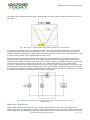
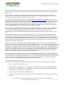
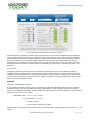
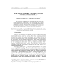
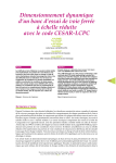
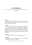
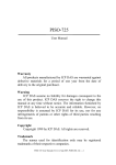
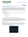
Exclusive Technology Feature
ISSUE: August 2012
Testing Power Supply Compliance To Energy Efficiency Standards
by Silvestro Fimiani, Power Integrations, San Jose, Calif.
Over the last several years, leading worldwide standards organizations, including the Environmental Protection
Agency’s Energy Star program, the European Commission’s Code of Conduct and the California Energy
Commission (CEC), have defined new efficiency requirements for external power supplies. These standards
demand that designers test their products for active-mode efficiency and no-load power consumption to high
levels of accuracy. To help simplify that process and accelerate product development, this article will describe a
relatively straightforward way to measure compliance to these evolving energy efficiency standards and offer a
few testing tips.
Basic Requirements
We’ll begin with the equipment needed to perform these tests. You will need four components to accurately
measure your product’s efficiency:
1. A wattmeter
2. A programmable ac source
3. An electronic load
4. Two digital multimeters (one must be a high-resolution current meter)
Next, a few general guidelines will help you achieve accurate results. First, since the energy efficiency
compliance measurement of a power supply is a system-level test that includes losses in the input and output
cables, you must ensure that the same cables used in this testing process are used in the final product. Second,
it is important to note that these tests require long temperature-stabilization periods between output line and
input line voltage changes. Therefore, expect the tests to take several hours to complete. Finally, every time
you alter your product design, these tests must be repeated to ensure accurate results.
Maximizing Accuracy
This test requires measurement of both no-load input power and active-mode efficiency of the supply. To
calculate efficiency one must measure both input and output power. When measuring input power, the selection
of the proper power source is crucial. As the graph in Fig. 1 illustrates the use of raw ac power from a wall
outlet and Variac introduces inaccuracy into the measurement. To ensure the testing is performed at a precise
input voltage, use a programmable ac source instead.
Fig. 1. Comparison of raw mains ac quality vs. a programmable ac power source.
© 2012 How2Power. All rights reserved.
Page 1 of 6
Exclusive Technology Feature
The graph in Fig. 2 depicts the output from a programmable ac source. Note the incoming waveform is a pure
sine wave.
Fig. 2. Power factor = cosine of phase angle between voltage and current waveform.
To make this measurement we use a wattmeter because it factors in the effect of power factor, cosine of the
angle between the voltage and current waveforms (cos φ). It is important to note that the energy efficiency
standard demands an input-power-measurement uncertainty of less than 2% for power measurements of 0.5 W
or greater and 10 mW for power measurements less than 0.5 W.
Wattmeters from several leading instrument manufacturers can be configured to meet these requirements.
Since a wattmeter features both a current- and voltage-sensing element, the voltage-sensing element can be
configured either before or after the input current-sense element. Typically, information on how to configure the
instrument can be found in its user manual. For low- or no-load measurements, you can achieve better
accuracy by configuring the voltage sense before the current-sense element. This prevents the current from the
voltage-sense element from being measured by the current-sense element. Given that the current consumed by
the voltage-sense element is typically greater than the allowable 10 mW at 230 Vac, this configuration is critical
to meeting the standard’s low measurement-uncertainty requirements.
Fig. 3. Wattmeter connections. Connect voltage sense before current sense for low or no-load
measurements.
High-Power Applications
Higher-power designs present different issues. In these applications the power loss in the voltage-sense
element is so small, the voltage-sense element can be connected after the current sense to locate it close to the
power supply input. This approach prevents the voltage drop across the current-sense element and the internal
© 2012 How2Power. All rights reserved.
Page 2 of 6
Exclusive Technology Feature
wiring of the wattmeter from being incorrectly included in the power measurement. That, in turn, can lead to
lower efficiency calculations. By setting the meter to average over 32 (or 64) samples you can generate more
stable results.
You will need two multimeters to measure output power; one to measure output voltage and the other to
measure current. Use the higher-resolution meter to measure current. Since output power is purely dc, it is
calculated by multiplying output voltage times output current.
To simplify the task of determining whether the specifications of your power supply comply with worldwide
regulations, Power Integrations has developed a helpful Energy Compliance Calculator. The targets for no-load
and active-mode efficiency are derived from the nameplate rating of each power supply. That rating is simply
the rated output marked on the power supply case and represents the minimum rated output power of the
supply at room temperature and nominal line. As an example: a constant-voltage, constant-current charger
with a nameplate rating of 5 V, 350 mA will deliver 5 V, 350 mA minimum.
Once you enter the nameplate output power rating for your power supply, the calculator will automatically tell
you the target values for compliance to the energy standards relevant to your design. Designs that accept
universal input voltages require measurements made at both 115 Vac, 60 Hz and 230 Vac, 50 Hz.
Measurements for single-input designs should be made at the nominal line voltage of either 115 Vac or 230
Vac.
To demonstrate this process let’s look at the test procedure for a 5-V, 350-mA cell phone charger rated for
universal input. We begin with a series of tests to measure active-mode efficiency at 115 Vac, 60 Hz. Activemode efficiency is the average of efficiencies measured at 25%, 50%, 75% and 100% of the nameplate rating
at a nominal line-input voltage and nominal line frequency. Since the nameplate load rating of this charger is
350 mA, efficiency must be measured at the following currents: full load (350 mA), 75% load (262 mA), 50%
load (175 mA) and 25% load (88 mA.)
Begin the test process by warming up the power supply for 30 minutes. To make the first measurement at
100% load, connect the power supply to an ac source and apply a 60-Hz, 115-Vac input. Gradually increase the
load on the power supply to 100% and allow at least 30 minutes for the circuit to reach thermal equilibrium and
the input power reading to stabilize. Before recording any measurements, make sure no oscilloscope probe or
other meter is connected to the circuit. In some cases you may need to manually set the voltage and/or current
range of the wattmeter to prevent it from auto-ranging and giving fluctuating results. The same measuring
instrument, in two different ranges, will typically have different levels of accuracy. Typically, the operator’s
manual will indicate the range that will generate the highest accuracy.
Once the circuit has reached thermal equilibrium, take the initial power reading from the wattmeter. Wait five
minutes and then take a second reading. If you find less than 5% difference between the two readings, record
the second reading. If the difference is larger than 5%, you should wait another five minutes and continue to do
so until two successive readings are within 5% of one another. Alternatively, you can use the “integration
mode,” available on most wattmeters and described in the following section.
Calculating Integral Input Power
To measure the input power of a design where the input power varies over time, take the following steps:
1. Set your wattmeter to integration mode.
2. Set the interval of integration for your wattmeter to capture approximately one full cycle of variable
input power. (The longer the duration, the higher the accuracy of results. We recommend integrating
over a period of 1 minute for most applications.)
3. Read the input energy from your wattmeter as W-hr.
4. Divide this number by the interval of integration. Make sure to adjust the time units so they cancel. For
example:
Input Energy (W-hr)/Measurement Interval (min) * 60 mins/1 hr = Input Power (W).
© 2012 How2Power. All rights reserved.
Page 3 of 6
Exclusive Technology Feature
In this example, the output current is recorded as 0.35 A and the output voltage is 6.124 V from the
multimeters, giving an output power of 2.14 W.
Efficiency is calculated as:
Efficiency at full load
= Pout/Pin
= 2.14 W/3.14 W
= 68.2%
To make the next measurement, adjust the load to 75% or 262 mA. When using the averaging feature on the
wattmeter, remember to allow at least one minute for the reading to stabilize. Then, record the input power
from the wattmeter. Wait five minutes, record again and use the <5% difference rule to decide whether to use
the value or calculate the integral input power.
In this example, the output current is recorded as 0.262 A and the output voltage is 6.502 V, giving an output
power of 1.704 W. Efficiency is then calculated as:
Efficiency at 75% load = 1.704 W/2.42 W
= 70.4%
This procedure should then be repeated for 50% and 25% load levels.
Measuring No-Load Input Power
To measure no-load input power, disconnect the output load and all output multimeters from your power
supply. Next, turn off the ac input and configure your wattmeter with the voltage-sense element before the
current-sense element. Take an initial power reading from the wattmeter and wait five minutes before taking a
second reading. As we have discussed in previous test procedures, record the second reading if the difference
between the two readings is less than 5%. If not, you must integrate the input power and divide by the time
period of integration using the process we described earlier.
This completes testing at 115 Vac. Next, you must reattach your load and output multimeters and increase the
input voltage to 230 Vac. Repeat all the previous tests at the new line voltage. Remember to set up your
wattmeter appropriately for your power range. Once testing is complete you should have a complete set of data
listing the results for all four load levels at both line voltages. (To ensure accurate measurements when
changing line voltage, see the tip “Changing Input Voltage” in the appendix.)
At this point you can open the Efficiency Compliance Calculator and enter the nameplate specification in the top
input fields and the newly generated test data in the columns on the left side (Fig. 4.)
© 2012 How2Power. All rights reserved.
Page 4 of 6
Exclusive Technology Feature
Fig. 4. Data entered into PI Efficiency Compliance Calculator.
Power Integration’s calculator computes active-mode efficiency as the equally-weighted average of efficiency
across all load levels. The fields on the right side of the screenshot above show various efficiency standards.
The calculator automatically calculates compliance requirements for active-mode efficiency and no-load input
power and compares your test results with the standards requirements. To simplify analysis of results, it
highlights those results that meet requirements in green and those that do not in red. (For those not using
Power Integration’s calculator to perform efficiency calculations, see the test tip “Calculating By Hand,” in the
appendix.)
Conclusion
As leading standards organizations focus on eliminating wasted power, they are developing increasingly
stringent efficiency requirements for external power supplies. At the same time, efforts to synchronize these
standards around the globe promise to bring conformity from region to region. By following the test methods
outlined above, designers can ensure their power supplies meet these emerging regulations and take the first
step to accessing worldwide markets.
Appendix
Test Tip: Calculating by Hand
If you decide to calculate values by hand, it is important to note that standards requirements are rounded to
two digits for both no-load requirements and active-mode efficiency. This seemingly minor point can play a
major role in standards compliance. Take the sample calculation below for minimum efficiency using the Energy
Star formula for a 12-V, 1.1-A supply:
Nameplate power = 12 V x 1.1 A = 13.2 W
ηmin ≥ [0.0626 x ln x (13.2)]
≥ 0.784 or 78.4%
≥ 0.78 or 78% rounded to two digits
Now let’s look at an example that shows the effect of rounding using measured results for the same 12-V, 1.1-A
supply:
© 2012 How2Power. All rights reserved.
Page 5 of 6
Exclusive Technology Feature
ηavg = (η25 + η50 + η75 + η100)/ 4
= (79.2 + 78.4 + 75.9 + 80.5)/4
= 0.785 or 78.5%
= 0.79 or 79% rounded to two digits
As the measured average is 79%, the power supply meets the standard’s requirement of 78% efficiency.
Test Tip: Changing Input Voltage
Are you measuring no-load power consumption and planning to change input voltage during testing? Always
apply full load to the output during this transition. Why? Under no load the input bulk capacitor takes a long
time to discharge. If the output is left with no load connected when the input voltage is dropped from high line
to low line, the capacitor will support the dc bus for a long period of time before drawing power from the ac
input. That, in turn, causes the power supply to have a no-load input power of 0 W. To avoid this problem begin
with the power supply fully loaded and only then remove all output loads before beginning the measurement.
About The Author
Silvestro Fimiani is product marketing manager of appliance and industrial
applications at Power Integrations (PI). Prior to joining PI in 2005, Silvestro
served as director of engineering of high-power products at International
Rectifier. He holds a Bachelor of Arts in Physics from the University of Naples,
Italy.
For further reading on power supply efficiency issues, see the How2Power Design Guide, select the Advanced
Search option, go to Search by Design Guide Category, and select “Efficiency” in the Design Area category.
© 2012 How2Power. All rights reserved.
Page 6 of 6