1
4100P – TOPSIDE PROCESSOR
Table Of Contents
1. Introduction ……………………………………………………………………………………………………………. 6
2. Overview ……………………………………………………………………………………………………………..... 6
2.1. Product Specifications …………………………………………………………………………….. 5
2.2. Operational Overview ……………………………………………………………………………… 6
2.2.1. Item descriptions ……………………………………………………………………… 8
3. Installation and Connecting the System ……………………………………………………………….. 9
3.1. Setup ………………………………………………………………………………………………………. 9
3.2. LED Diagnostics .………………….……………………………..…………………………..…….10
3.3. Ethernet Connections …………………………………………………….………………………. 11
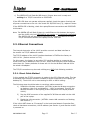
3.3.1. Direct Cable Method ……………………………………………………………….. 11
3.3.2. Wireless Method …………………………………………………….……………….. 12
4. System IP address configurations …………………………………………………….…………………. 13
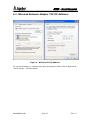
4.1. Wireless Network Adapter TCP/IP Address: …………………………………………. 14
4.2. Local Area Network Adapter TCP/IP Address: ……………………………………… 15
4.3. 4100P Interface Hardware TCP/IP Address: …………………………………………. 15
4.4. 4100P Wireless Adapter TCP/IP Address ………………………………………………..15
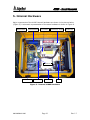
5. Internal Hardware ……………………………………………………………………………………………….. 16
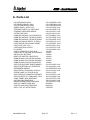
6. Parts List ………………………………………………………………………………………………………………
18
7. Cables …………………………………………………………………………………………………………………… 19
8. Contact and Service Information …………………………………………………………………………. 23
9. Returned Material Authorization ………………………………………………………………………….. 24
Appendices
Appendix A – ACI Module ………………………………………………………………………………………… A-1
Appendix B – Wireless Setup ………………………………………………………………………………….. B-1
Appendix C – EdgeTech System Backup/Restore …………………….……………………………. C-1
Appendix D - Netlink Module …………………………………………………….…………..……………….. D-1
Figures
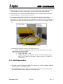
Figure 1 – Interface Panel ……………………………………………………………………………………….… 9
Figure 2 – DC & Ethernet Cable ……………………………………………………………………………….. 10
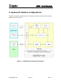
Figure 3 – 4100 Network Configuration Diagram……………………………………………………... 13
Figure 4 – Wireless TCP/IP Address …………………….…………………………………………………… 14
Figure 5 – LAN TCP/IP Address …………………….……………………………………………………….…. 15
Figure 6 – Internal 4100P Hardware …………………….…………………………………….…………….16
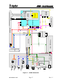
Figure 7 – 4100P Schematic …………………………………………….………….……………………..…….17
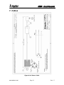
Figure 8 – AC Power Cable …………………….…………………………………….………………………..…. 19
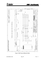
Figure 9 – DC Power & Ethernet Cable ….…………………………………….………………………..….20
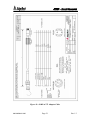
Figure 10 – 4100P to 272 Adapter Cable ….…………………………………….……………………..… 21
990-0000043-1000
Page 4
Rev.1.3