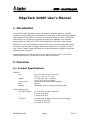
1
4100P SIDE SCAN TOPSIDE PROCESSOR USER’S MANUAL Revision: 1.3 /June, 2007 Email: [email protected] Web: http://www.edgetech.com PO Box 850 4 Little Brook Road West Wareham, MA 02576 Tel: (508) 291-0057 Fax: (508) 291-2491 4100P – TOPSIDE PROCESSOR WARRANTY All equipment manufactured by EdgeTech is warranted against defective components and workmanship for a period of one year after shipment. Warranty repair will be done by EdgeTech, free of charge. Shipping costs are to be borne by the customer. Malfunction due to improper use is not covered in the warranty and EdgeTech disclaims any liability for consequential damage resulting from defects in the performance of the equipment. No product is warranted as being fit for a particular purpose and there is no warranty of merchantability. This warranty applies only if: i. The items are used solely under the operating conditions and in the manner recommended in Seller’s instruction manual, specifications, or other literature. ii. The items have not been misused or abused in any manner or repairs attempted thereon. iii. Written notice of the failure within the warranty period is forwarded to Seller and the directions received for properly identifying items returned under warranty are followed. iv. The return notice authorizes Seller to examine and disassemble returned products to the extent Seller deems necessary to ascertain the cause for failure. The warranties expressed herein are exclusive. There are no other warranties, either expressed or implied, beyond those set forth herein, and Seller does not assume any other obligation or liability in connection with the sale or use of said products. Any product or service repaired under this warranty shall be warranted for the remaining portion of the original warranty period only. Equipment not manufactured by EdgeTech is supported only to the extent of the original manufacturer’s warranties. 990-0000043-1000 Page 2 Rev.1.3 4100P – TOPSIDE PROCESSOR WARNING This equipment contains static sensitive devices that are extremely sensitive to static electrical charges, which may be developed on the body and the clothing. Extreme care should be taken when handling these devices both in and out of the circuit board. Normal handling precautions involve the use of anti-static protection materials and grounding straps for personnel. This equipment generates, uses and can radiate radio frequency energy, and if not installed properly may cause interference to radio communications. It has not been tested to compliance to the appropriate FCC rules designed to provide reasonable protection against such interference when operated in a commercial environment. Operation of this equipment in a residential area may cause interference, in which case the user, at his own expense, will be required to take whatever measures needed to correct the interference. It is the user’s responsibility to verify that the system complies with the applicable FCC emission limits. High Voltage may be present in the towfish, power amplifier and the topside processor. Use caution when the electronics are removed from their containers for servicing. Operation with improper line voltage could cause serious damage to the equipment. 990-0000043-1000 Page 3 Rev.1.3 4100P – TOPSIDE PROCESSOR Table Of Contents 1. Introduction ……………………………………………………………………………………………………………. 6 2. Overview ……………………………………………………………………………………………………………..... 6 2.1. Product Specifications …………………………………………………………………………….. 5 2.2. Operational Overview ……………………………………………………………………………… 6 2.2.1. Item descriptions ……………………………………………………………………… 8 3. Installation and Connecting the System ……………………………………………………………….. 9 3.1. Setup ………………………………………………………………………………………………………. 9 3.2. LED Diagnostics .………………….……………………………..…………………………..…….10 3.3. Ethernet Connections …………………………………………………….………………………. 11 3.3.1. Direct Cable Method ……………………………………………………………….. 11 3.3.2. Wireless Method …………………………………………………….……………….. 12 4. System IP address configurations …………………………………………………….…………………. 13 4.1. Wireless Network Adapter TCP/IP Address: …………………………………………. 14 4.2. Local Area Network Adapter TCP/IP Address: ……………………………………… 15 4.3. 4100P Interface Hardware TCP/IP Address: …………………………………………. 15 4.4. 4100P Wireless Adapter TCP/IP Address ………………………………………………..15 5. Internal Hardware ……………………………………………………………………………………………….. 16 6. Parts List ……………………………………………………………………………………………………………… 18 7. Cables …………………………………………………………………………………………………………………… 19 8. Contact and Service Information …………………………………………………………………………. 23 9. Returned Material Authorization ………………………………………………………………………….. 24 Appendices Appendix A – ACI Module ………………………………………………………………………………………… A-1 Appendix B – Wireless Setup ………………………………………………………………………………….. B-1 Appendix C – EdgeTech System Backup/Restore …………………….……………………………. C-1 Appendix D - Netlink Module …………………………………………………….…………..……………….. D-1 Figures Figure 1 – Interface Panel ……………………………………………………………………………………….… 9 Figure 2 – DC & Ethernet Cable ……………………………………………………………………………….. 10 Figure 3 – 4100 Network Configuration Diagram……………………………………………………... 13 Figure 4 – Wireless TCP/IP Address …………………….…………………………………………………… 14 Figure 5 – LAN TCP/IP Address …………………….……………………………………………………….…. 15 Figure 6 – Internal 4100P Hardware …………………….…………………………………….…………….16 Figure 7 – 4100P Schematic …………………………………………….………….……………………..…….17 Figure 8 – AC Power Cable …………………….…………………………………….………………………..…. 19 Figure 9 – DC Power & Ethernet Cable ….…………………………………….………………………..….20 Figure 10 – 4100P to 272 Adapter Cable ….…………………………………….……………………..… 21 990-0000043-1000 Page 4 Rev.1.3 4100P – TOPSIDE PROCESSOR Figure 11 – 4100P Tow Cable ….…………………………………….……………………..…………………. 22 990-0000043-1000 Page 5 Rev.1.3 4100P – TOPSIDE PROCESSOR EdgeTech 4100P User’s Manual 1. Introduction The 4100P Portable Topside Processor provides an interface between a laptop computer running EdgeTech's DISCOVER 4100 Side Scan Sonar acquisition software, and a Model 272-TD towfish. The end user need only supply a source of GPS data and either AC or DC power to complete the acquisition package. The complete system with the 4100P and 272-TD is the Model 4100 Side Scan Sonar System. The 560P unit is a self contained, portable unit with all interface and power supply electronics housed within a rugged, waterproof (when the lid is closed) Storm ® case. There is space inside the closed unit to accommodate an EdgeTech supplied laptop personal computer. The data and control interface between the laptop and the 4100P is via TCP/IP protocols and may be via wireless or direct cable connections. 2. Overview 2.1. Product Specifications Physical: Size Weight Construction Color Sealing Power requirements: DC Input voltage AC Input 990-0000043-1000 39 cm D x 49 mm W x 19 mm H (15.2 in x 19.2 in x 7.3 in) 13.2 kg (29.0 lbs.) w/ laptop 10 kg (22.0 lbs.) w/o laptop High-impact structural polypropylene Yellow Watertight cover O-ring seal, w/purge valve 11 to 30 VDC 60 watts maximum 3 Amps at 12 VDC 2 Amps at 24 VDC 120/240 VAC 80 watts maximum (Auto-ranging) 0.6 Amps at 120 VAC 0.4 Amps at 240 VAC Page 6 Rev.1.3 4100P – TOPSIDE PROCESSOR Environment: Temperature range: Operating: Storage: Relative humidity: Operating: Non-operating: Tow-Fish Interface: Data Input: 0°C to 40°C (32°F to 104°F) (shade conditions) -20°C to 60°C (-4°F to 140°F) 0 to 80% (non-condensing) 0 to 100% EdgeTech model 272-TD, 2-channel analog side scan, either 100 or “500" kHz. +750 to +800 VDC Towfish Power: 4100P/Laptop Processor Interfaces: 1. Direct Ethernet Connection (10BaseT, TCP/IP) 2. Wireless Ethernet (802.11b) Laptop Specifications: Due to continuous product evolution in this area a firm specification cannot be provided. The nominal specification for the EdgeTech supplied laptop is: Notebook computer Operating System Processor Memory Hard drive Screen size Wireless : : : : : : : Sony Vaio-FS540P, or equivalent Windows XP Professional Pentium M 730, 1.6 GHz 512 Mbytes 80 GBytes 15.4” - 1280 x 800 typical Intel® Centrino™ Supplied Components: 4100P Portable Processor case with integral interface electronics Laptop processor with DISCOVER 4100 Side Scan Sonar acquisition software System Recovery Disk AC power cable DC Power & Ethernet cable Spares Kit Manuals 990-0000043-1000 Page 7 Rev.1.3 4100P – TOPSIDE PROCESSOR 2.2. Operational Overview 2.2.1. Item descriptions 4100P Portable Processor Case The processor case supplied is based on the Hardigg Storm® case series, and provides a waterproof enclosure of the 272-TD Towfish power supply and interface electronics. The power, towfish and Ethernet cable connectors are mounted on a recessed, waterproof panel, with LED indicators and On/OFF switch. Laptop processor The laptop style processor is used to run EdgeTech's DISCOVER 4100 Side Scan Sonar software acquisition package. This provides control, storage and display of the towfish data. The data is presented on a color waterfall display and is stored in XTF or JSF formats on a hard disk. (See http://www.edgetech.com/topsidelevel3discover.html) A user supplied GPS with NMEA interface strings is required for positioning data. AC power Cable The supplied 2 meter AC power cable, shown in Figure 8, is used to connect the unit to a source of AC power. The source may be 50/60Hz and either 120 or 240 volts (nominal). DC Power & Ethernet Cable This 7.6m (25') long cable, shown in Figure 9, is used to supply either one or both of the following functions: • • DC power for the unit. (Typically for battery powered installations) YELLOW wire is positive, BROWN wire is negative or Red wire is Positive, Black wire is Negative Direct Ethernet 10BaseT connection to the Laptop. NOTE: AC or DC power may be connected simultaneously or individually. 272-TD Tow Cable Adapter This is supplied for installations where the EdgeTech 272-TD standard 7 Pin Amphenol tow cable is used for connection to the towfish. It provides the connector type changeover necessary (see Figure 10). NOTE: In this case the tow cable is NOT waterproof at the Male/Female Amphenol connection point, and this should be suitably protected in wet environments/installations. A direct 4100P – towfish cable assembly is recommended for wet installations. 990-0000043-1000 Page 8 Rev.1.3 4100P – TOPSIDE PROCESSOR 3. Installation and Connecting the System 3.1. Setup 1) Check the unit is OFF. Figure 1 - Interface Panel 990-0000043-1000 Page 9 Rev.1.3 4100P – TOPSIDE PROCESSOR 2) Connect the 4100P unit to a source of AC and/or DC power using either the DC & Ethernet cable or the AC power cable. (Check system power specifications) 3) Connect the 4100P via the tow cable connection to the towfish using either the supplied adapter or a direct cable connection. 4) Connect the Laptop to the 4100P unit using either the Wireless connection, or via the 10BaseT direct Ethernet cable (which is part of the DC & Ethernet cable assembly). The Ethernet cable may be extended up to 100 feet using a Category 5 Ethernet patch cable and Ethernet connector. A crossover or direct cable may be used. Figure 2 - DC & Ethernet Cable 5) Operate the ON/OFF switch to the ON position (UP). NOTE: The switch operates in both the AC and DC power input modes. Observe the Front Panel LEDS. The correct Status should be: Power LED (RED) = ON Status LED (Green) = ON after about 5 seconds and remain ON. NOTE: The Trigger LED (Orange) = ON only when 272 towfish is transmitting. 3.2. LED Diagnostics: a) The RED Power LED should be always lit if power (AC or DC) is applied AND the power switch is in the ON position. b) If the GREEN LED goes off after 5-10 seconds, there is an internal failure that will require attention by a qualified service technician. 990-0000043-1000 Page 10 Rev.1.3 4100P – TOPSIDE PROCESSOR c) The GREEN LED will flash On/Off about 1/2 hertz when unit is ready and waiting for a TCP/IP connection to DISCOVER. If the RED LED does not operate with power applied, check the status of switch and all power connections to the unit. Also check the 5A/250V fuse (F1); replace if blown. If the GREEN LED is flashing, check the Laptop Ethernet connections and DISCOVER 4100 status. Note: The GREEN LED will flash if there is a valid Ethernet link between the Laptop and the 4100P unit, but DISCOVER is not running, or is incorrectly configured. The GREED LED will also flash if DISCOVER is running but there is no valid TCP/IP connection between the Laptop and the 560P unit. 3.3. Ethernet Connections The internal electronics of the 4100P provides a control and data interface to the towfish via TCP/IP address & socket. The TCP/IP address of the 4100P interface hardware is FIXED at the factory at 192.9.0.101. (Socket number is 1700) For this reason, the laptop (or any other) PC interface wishing to connect to the 4100P must use an address of 192.9.0.XXX., where XXX being any valid IP address other than 101. Factory defaults for these are 100 for the Wireless LAN and 99 for the wired LAN adapter. The TCP/IP connection may be made utilizing any ONE of the following methods. 3.3.1. Direct Cable Method In this method, the TCP/IP connection is made via the DC & Ethernet cable. This has a standard RJ45 Ethernet connector suitable for direct connection to the Laptop (or desktop PC). The 4100P unit is auto-sensing for MDI or MDI-X cabling. The following steps should be taken to use direct cable connection: 1) Disable the Wireless connection. (ACTION: locate the Wireless connection on desktop, right click, and disable it …, OR if so equipped, Turn OFF the Wireless function on the Laptop (a Blue LED/button on Compaq Presario X1000). 2) Plug the RJ45 connector of the supplied DC & Ethernet cable into the LAN port of the Laptop. 3) Enable the LAN connection. (ACTION: Locate LAN connection on Desktop, and Enable it…). If the LAN is NOT shown as “Connected” in the Local Area Network Properties Box, check all hardware connections, LAN IP address (see Section 4), and that the 4100P is powered on. 990-0000043-1000 Page 11 Rev.1.3 4100P – TOPSIDE PROCESSOR 3.3.2. Wireless Method TM In this method the Intel® Centrino wireless networking capability of the laptop will be used. The following steps should be taken: 1) Disable the LAN connection of the laptop. (ACTION: Locate LAN connection on Desktop, double click, and Disable it… OR simply unplug LAN cable from laptop). 2) Enable the wireless connection. (ACTION: locate Wireless connection Icon on desktop, right click, and Enable …OR if so equipped Turn ON the wireless function on the laptop ). The wireless connection should show a valid connection to the "sonarlink" wireless network after 10-15 seconds. If there are problems with this link, refer to Section 4. 990-0000043-1000 Page 12 Rev.1.3 4100P – TOPSIDE PROCESSOR 4. System IP address configurations The factory supplied configurations for the laptop's wireless and direct cable network adapters are shown below. Figure 3 – 4100 Network Configuration Diagram 990-0000043-1000 Page 13 Rev.1.3 4100P – TOPSIDE PROCESSOR 4.1. Wireless Network Adapter TCP/IP Address: Figure 4 - Wireless TCP/IP Address For more information on wireless setup and configuration please refer to Appendix B, “4xxxP System – Wireless Setup” 990-0000043-1000 Page 14 Rev.1.3 4100P – TOPSIDE PROCESSOR 4.2. Local Area Network Adapter TCP/IP Address: Figure 5 - LAN TCP/IP Address The Network Adapter Media configuration can be setup for Auto or 100Mb/s link speed for short (8m) cables. For longer cables we recommend a setting of 10Mbit/s, Half Duplex mode. 4.3. 4100P Interface Hardware TCP/IP Address: This is FIXED at 192.9.0.101. 4.4. 4100P Wireless Adapter TCP/IP Address The 560P Interface unit has a built in Linksys Wireless adapter (Model WET11) . This Wireless adapter has its own TCP/IP address for configuration and status reporting (Refer to Linksys Manuals). This is set by EdgeTech at 192.9.0.255. (Note the Linksys default is 192.168.1.255). This IP address is not used during normal system operation. 990-0000043-1000 Page 15 Rev.1.3 4100P – TOPSIDE PROCESSOR 5. Internal Hardware Major components of the 4100P internal hardware are shown in the picture below (Figure 5). A schematic representation of the same hardware is shown in Figure 6. Ethernet Switch Wireless Ethernet AC Line Filter Power Supply, 15 VDC Control Panel Net Burner Netlink Power Board ACI Board Fan Figure 6 - Internal 4100P Hardware 990-0000043-1000 Page 16 Rev.1.3 4100P – TOPSIDE PROCESSOR P1 3 4 2 1 P1 Wireless Modem E-NET E-NET E-NET 5 VOLTS J10 5 VOLTS P1 Power Board 3 G 4 Ground (AC) 2 AC Line Filter 1 AC E-NET FISH POWER PANEL LED's EXT. POWER ACI Board TRIGGER J8 P8 J5 P5 J2 P2 J4 P4 J1 P3 J11 P11 NetBurner J3 P2 J2 P2 P2 P1 Netlink Board J3 P1 J10 Ethernet Switch J7 P1 W12 P2 J2 PORT SS STARBOARD SS Fan Control Panel AC Ground (AC) AC EXTERNAL POWER - RED Ground (AC) E-NET P7 J2 J4 J6 P10 P9 EXTERNAL POWER - BLACK AC EXTERNAL POWER FISH POWER PORT SS STARBOARD SS TRIGGER PANEL LED's E-NET Ground (AC) Power Supply, 15 Volt Chassis Ground Main Cable J9 P9 J1 P1 J6 P6 F1 J1 SW1 J3 J7 D1 TRIGGER F2 D2 READY D3 POWER Rev.1.3 Page 17 990-0000043-1000 J6 P2 W13 P1 J5 P11 P2 P3 Figure 7 – 4100P Schematic 4100P – TOPSIDE PROCESSOR 6. Parts List LED,RED,SEALED,560P LED,GREEN,SEALED, 560P LED,YELLOW,SEALED,560P POWER SUPPLY,AC/DC,15V ETHERNET SWITCH, 4 PORT,MINI ETHERNET WIRELESS BRIDGE FILTER,LINE,5AMP CONN,BULKHEAD,8 PIN,F,MCBH8F-B CONN,BULKHEAD,3 PIN,MALE,MCBH3 CONN,BULKHEAD,8 PIN,MALE,MCBH8 CONN,LOCKING SLEEVE,F,15 SHELL FUSE,HOLDER,5X20,PANEL MOUNT FAN,12VDC,3.62"X1.0" FAN GUARD,BLK PLASTIC PC,LAPTOP FUSE,1/32AMP,250V,FAST-BLO CABLE,CAT.5E,YELLOW,3M,PORTABLE SWITCH,ON /OFF,560P BOOT,CAP,SWITCH COVER,560P CONN,DUMMY PLUG,MICRO,MCDC8F CONN,DUMMY PLUG,MICRO,MCDC8M CONN,DUMMY PLUG,MICRO,MCDC3F ASSY,PCB,PORTABLE POWER BOARD ASSY,PCB,NETLINK,ACI INTERFACE NETBURNER MODULE DUAL SERIAL I/O BOARD, PCMCIA1 SCREW,PANEL,10-32X5/8 BK SS ASSY,CABLE,DC POWER & ETHERNET ASSY,ADAPTER 272 TOWCABLE, 560P PANEL,FRONT,56XP,PORTABLE NUT,BAR,560P,PORTABLE GASKET,RUBBER,56XP,PORTABLE ASSY,AC POWER CORD,560P CASE,YELLOW,56XP,PORTABLE ASSY, PCB, ACI WITH EPROM 990-0000043-1000 020-LGAASRD-1000 020-LOPSHGN-1000 020-LOPSHYW-1000 030-0000008-1000 040-0000038-1000 040-0000047-1000 040-000LF00-1000 067-F008B02-1000 067-M003B02-1000 067-M008B02-1000 067-N000L00-1015 070-HLDR003-1000 099-F001P00-1000 100-0000072-1000 170-0000082-1000 190950 191167 193941 194042 194743 194840 194948 200-0000092-1000 200-0000090-1000 040-NETBURN-1000 200-0000100-1000 22810-10FCP 300-0000267-1000 300-0000268-1000 350-0000275-0300 350-0000420-0300 350-0000421-0300 B958608 B980049 C958434 Page 18 Rev.1.3 4100P – TOPSIDE PROCESSOR 7. Cables Figure 8: AC Power Cable 990-0000043-1000 Page 19 Rev.1.3 4100P – TOPSIDE PROCESSOR Figure 9: DC Power & Ethernet Cable 990-0000043-1000 Page 20 Rev.1.3 4100P – TOPSIDE PROCESSOR Figure 10: 4100P to 272 Adapter Cable 990-0000043-1000 Page 21 Rev.1.3 4100P – TOPSIDE PROCESSOR Figure 11: 4100P Tow Cable 990-0000043-1000 Page 22 Rev.1.3 4100P – TOPSIDE PROCESSOR 8. Contact and Service Information For product service or support call: EdgeTech 4 Little Brook Road West Wareham, MA 02576 Tel: (508) 291-0057 Fax: (508) 291-2491 Email: [email protected] If it is necessary to return the equipment for service, you must obtain a Returned Material Authorization (RMA) number prior to returning any equipment to EdgeTech. This is to assist EdgeTech in recognizing your equipment when it arrives at our Receiving dock, and to assist us in tracking your equipment while it is at our facility. 990-0000043-1000 Page 23 Rev.1.3 560P – TOPSIDE PROCESSOR 9. Returned Material Authorization It is necessary to obtain a Returned Material Authorization (RMA) number prior to returning any equipment to EdgeTech. This will help EdgeTech in recognizing your equipment when it arrives at our receiving dock, and to assist us in tracking your equipment while it is at our facility. The material should be shipped to the address indicated above. Please refer to the RMA number on all documents and correspondence as well. All returned material must be shipped prepaid. Freight collect shipments will not be accepted. The following steps apply only to material being returned from outside the Continental United States. These steps should be followed carefully to prevent delays and additional costs. 1. All shipments must be accompanied by three copies of your proforma invoice, showing the value of the material and the reason for its return, if the reason is for repair it must be clearly stated in order to come through customs faster and without duties being charged. Whenever possible, please send copies of original export shipping documents with the consignment. 2. If the value of the equipment is over $1000, the following Shipper’s oath must be sent with the invoice. This oath can be typed on the invoice, or on a separate letterhead. “I, ______________________________, declare that the articles herein specified are the growth, produce, or manufacture of the United States; that they were exported from the United States from the port of _____________________, on or about _______________; that they are returned without having been advanced in value or improved in condition by any process of manufacture or any other means; and that no drawback, or allowance has been paid or admitted hereof.” Signed ______________________________ 3. If there is more than one item per consignment, a packing list must accompany the shipment. It is acceptable to combine the proforma invoice and packing list as long as the contents of each carton are clearly numbered and identified on the invoice. 4. Small items can be shipped prepaid directly to EdgeTech by FedEx, DHL, UPS, Airborne, etc. 5. If the equipment is the property of EdgeTech (formerly EG&G Marine Instruments Division) please insure for full value. 6. Fax one invoice, packing list, and copy of airway bill to EdgeTech upon shipment. 990-0000043-1000 Page 24 Rev. 1.2