1
Excelsior Diode-Pumped Visible CW Lasers
5
1
15
11
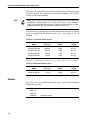
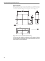
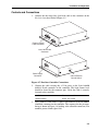
Figure 4-6: External Control Connector Pin Numbering
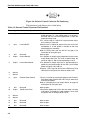
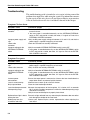
The function of each of these pins is listed below.
Table 4-1: External Control Connector Pin Functions
Pin
Type
1
Output
2
Description
Function
Laser OK
This pin is internally shorted to ground when the laser is in
stable operation, i.e., laser output power is at the specified level and the laser head temperature is within the
proper operating range.
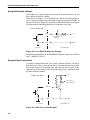
Pin 1 can be used as a switch for a laser emission indicator as shown in Figure 4-8.
Input
Laser ON/OFF
When this pin is shorted to ground, the laser will turn on
immediately (if +5 Vdc power is available to the laser
head through the controller).
Refer to “Turning the Laser On and Off” on page 4-7 for
instructions on using this input.
3
N/A
Reserved
Must be open
4
Output
Current Monitor
Pin 4 provides an output signal proportional to the current
of the diode pump laser. The scale is 100 mV/Amp, the
maximum signal is 160 mV (corresponding to 1.6 A).
5
Output
Laser Power Monitor
Pin 5 provides an output signal that is approximately proportional to the power output of the laser. At full output
power, the signal is 95–100 mV.
Example: a Pin 5 signal of 50 mV for the Excelsior-473-10
indicates that laser power has fallen to about 5 mW.
6
Ground
7
Ground
8
Input
External Power Control
This pin is used to vary the output power of the Excelsior532-100 and the Excelsior-532-150. This pin works only
for these two models.
Refer to “Changing the Laser Output Power” on page 4-9
for directions on using this input.
9
N/A
Reserved
Must be open.
10
Output
Diode Laser Alarm
Indicates the diode pump laser in the laser head is nearing
its end of life. To employ this “open collector” alarm, refer
to Figure 4-9 for an example of this circuit.
11
Ground
12
Ground
13
N/A
Reserved
Must be open.
14
N/A
Reserved
Must be open.
15
N/A
Reserved
Must be open.
4-6