1
SAFETY PRECAUTIONS
(Please read these instructions before using this equipment.)
Before using this product, please read this manual and the relevant manuals introduced in this manual
carefully and pay full attention to safety to handle the product correctly.
These precautions apply only to this product.
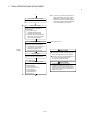
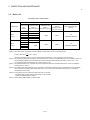
In this manual, the safety instructions are ranked as "DANGER" and "CAUTION".
DANGER
Indicates that incorrect handling may cause hazardous
conditions, resulting in death or severe injury.
CAUTION
Indicates that incorrect handling may cause hazardous
conditions, resulting in medium or slight personal injury or
physical damage.
CAUTION may also be linked to serious
Depending on circumstances, procedures indicated by
results.
In any case, it is important to follow the directions for usage.
Please save this manual to make it accessible when required and always forward it to the end user.
A-1
For Safe Operations
1. Prevention of electric shocks
DANGER
Never open the front case or terminal covers while the power is ON or the unit is running, as this
may lead to electric shocks.
Never run the unit with the front case or terminal cover removed. The high voltage terminal and
charged sections will be exposed and may lead to electric shocks.
Never open the front case or terminal cover at times other than wiring work or periodic
inspections even if the power is OFF. The insides of the Motion controller and servo amplifier are
charged and may lead to electric shocks.
Completely turn off the externally supplied power used in the system before mounting or
removing the module, performing wiring work, or inspections. Failing to do so may lead to electric
shocks.
When performing wiring work or inspections, turn the power OFF, wait at least ten minutes, and
then check the voltage with a tester, etc.. Failing to do so may lead to electric shocks.
Be sure to ground the Motion controller, servo amplifier and servomotor. (Ground resistance :
100 or less) Do not ground commonly with other devices.
The wiring work and inspections must be done by a qualified technician.
Wire the units after installing the Motion controller, servo amplifier and servomotor. Failing to do
so may lead to electric shocks or damage.
Never operate the switches with wet hands, as this may lead to electric shocks.
Do not damage, apply excessive stress, place heavy things on or sandwich the cables, as this
may lead to electric shocks.
Do not touch the Motion controller, servo amplifier or servomotor terminal blocks while the power
is ON, as this may lead to electric shocks.
Do not touch the built-in power supply, built-in grounding or signal wires of the Motion controller
and servo amplifier, as this may lead to electric shocks.
2. For fire prevention
CAUTION
Install the Motion controller, servo amplifier, servomotor and regenerative resistor on
incombustible. Installing them directly or close to combustibles will lead to fire.
If a fault occurs in the Motion controller or servo amplifier, shut the power OFF at the servo
amplifier’s power source. If a large current continues to flow, fire may occur.
When using a regenerative resistor, shut the power OFF with an error signal. The regenerative
resistor may abnormally overheat due to a fault in the regenerative transistor, etc., and may lead
to fire.
Always take heat measures such as flame proofing for the inside of the control panel where the
servo amplifier or regenerative resistor is installed and for the wires used. Failing to do so may
lead to fire.
Do not damage, apply excessive stress, place heavy things on or sandwich the cables, as this
may lead to fire.
A-2
3. For injury prevention
CAUTION
Do not apply a voltage other than that specified in the instruction manual on any terminal.
Doing so may lead to destruction or damage.
Do not mistake the terminal connections, as this may lead to destruction or damage.
Do not mistake the polarity ( + / - ), as this may lead to destruction or damage.
Do not touch the heat radiating fins of controller or servo amplifier, regenerative resistor and
servomotor, etc., while the power is ON and for a short time after the power is turned OFF. In this
timing, these parts become very hot and may lead to burns.
Always turn the power OFF before touching the servomotor shaft or coupled machines, as these
parts may lead to injuries.
Do not go near the machine during test operations or during operations such as teaching.
Doing so may lead to injuries.
4. Various precautions
Strictly observe the following precautions.
Mistaken handling of the unit may lead to faults, injuries or electric shocks.
(1) System structure
CAUTION
Always install a leakage breaker on the Motion controller and servo amplifier power source.
If installation of an electromagnetic contactor for power shut off during an error, etc., is specified in
the instruction manual for the servo amplifier, etc., always install the electromagnetic contactor.
Install the emergency stop circuit externally so that the operation can be stopped immediately and
the power shut off.
Use the Motion controller, servo amplifier, servomotor and regenerative resistor with the correct
combinations listed in the instruction manual. Other combinations may lead to fire or faults.
Use the Motion controller, base unit and motion module with the correct combinations listed in the
instruction manual. Other combinations may lead to faults.
If safety standards (ex., robot safety rules, etc.,) apply to the system using the Motion controller,
servo amplifier and servomotor, make sure that the safety standards are satisfied.
Construct a safety circuit externally of the Motion controller or servo amplifier if the abnormal
operation of the Motion controller or servo amplifier differ from the safety directive operation in the
system.
In systems where coasting of the servomotor will be a problem during the forced stop, emergency
stop, servo OFF or power supply OFF, use dynamic brakes.
Make sure that the system considers the coasting amount even when using dynamic brakes.
In systems where perpendicular shaft dropping may be a problem during the forced stop,
emergency stop, servo OFF or power supply OFF, use both dynamic brakes and electromagnetic
brakes.
A-3
CAUTION
The dynamic brakes must be used only on errors that cause the forced stop, emergency stop, or
servo OFF. These brakes must not be used for normal braking.
The brakes (electromagnetic brakes) assembled into the servomotor are for holding applications,
and must not be used for normal braking.
The system must have a mechanical allowance so that the machine itself can stop even if the
stroke limits switch is passed through at the max. speed.
Use wires and cables that have a wire diameter, heat resistance and bending resistance
compatible with the system.
Use wires and cables within the length of the range described in the instruction manual.
The ratings and characteristics of the parts (other than Motion controller, servo amplifier and
servomotor) used in a system must be compatible with the Motion controller, servo amplifier and
servomotor.
Install a cover on the shaft so that the rotary parts of the servomotor are not touched during
operation.
There may be some cases where holding by the electromagnetic brakes is not possible due to the
life or mechanical structure (when the ball screw and servomotor are connected with a timing belt,
etc.). Install a stopping device to ensure safety on the machine side.
(2) Parameter settings and programming
CAUTION
Set the parameter values to those that are compatible with the Motion controller, servo amplifier,
servomotor and regenerative resistor model and the system application. The protective functions
may not function if the settings are incorrect.
The regenerative resistor model and capacity parameters must be set to values that conform to
the operation mode, servo amplifier and servo power supply module. The protective functions
may not function if the settings are incorrect.
Set the mechanical brake output and dynamic brake output validity parameters to values that are
compatible with the system application. The protective functions may not function if the settings
are incorrect.
Set the stroke limit input validity parameter to a value that is compatible with the system
application. The protective functions may not function if the setting is incorrect.
Set the servomotor encoder type (increment, absolute position type, etc.) parameter to a value
that is compatible with the system application. The protective functions may not function if the
setting is incorrect.
Set the servomotor capacity and type (standard, low-inertia, flat, etc.) parameter to values that
are compatible with the system application. The protective functions may not function if the
settings are incorrect.
Set the servo amplifier capacity and type parameters to values that are compatible with the
system application. The protective functions may not function if the settings are incorrect.
Use the program commands for the program with the conditions specified in the instruction
manual.
A-4
CAUTION
Set the sequence function program capacity setting, device capacity, latch validity range, I/O
assignment setting, and validity of continuous operation during error detection to values that are
compatible with the system application. The protective functions may not function if the settings
are incorrect.
Some devices used in the program have fixed applications, so use these with the conditions
specified in the instruction manual.
The input devices and data registers assigned to the link will hold the data previous to when
communication is terminated by an error, etc. Thus, an error correspondence interlock program
specified in the instruction manual must be used.
Use the interlock program specified in the intelligent function module's instruction manual for the
program corresponding to the intelligent function module.
(3) Transportation and installation
CAUTION
Transport the product with the correct method according to the mass.
Use the servomotor suspension bolts only for the transportation of the servomotor. Do not
transport the servomotor with machine installed on it.
Do not stack products past the limit.
When transporting the Motion controller or servo amplifier, never hold the connected wires or
cables.
When transporting the servomotor, never hold the cables, shaft or detector.
When transporting the Motion controller or servo amplifier, never hold the front case as it may fall
off.
When transporting, installing or removing the Motion controller or servo amplifier, never hold the
edges.
Install the unit according to the instruction manual in a place where the mass can be withstood.
Do not get on or place heavy objects on the product.
Always observe the installation direction.
Keep the designated clearance between the Motion controller or servo amplifier and control panel
inner surface or the Motion controller and servo amplifier, Motion controller or servo amplifier and
other devices.
Do not install or operate Motion controller, servo amplifiers or servomotors that are damaged or
that have missing parts.
Do not block the intake/outtake ports of the Motion controller, servo amplifier and servomotor with
cooling fan.
Do not allow conductive matter such as screw or cutting chips or combustible matter such as oil
enter the Motion controller, servo amplifier or servomotor.
The Motion controller, servo amplifier and servomotor are precision machines, so do not drop or
apply strong impacts on them.
Securely fix the Motion controller, servo amplifier and servomotor to the machine according to
the instruction manual. If the fixing is insufficient, these may come off during operation.
A-5
CAUTION
Always install the servomotor with reduction gears in the designated direction. Failing to do so
may lead to oil leaks.
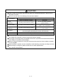
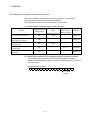
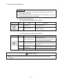
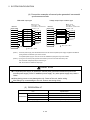
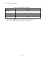
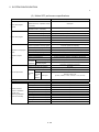
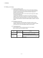
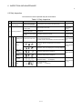
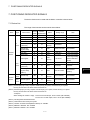
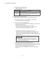
Store and use the unit in the following environmental conditions.
Environment
Ambient
temperature
Ambient humidity
Storage
temperature
Atmosphere
Conditions
Motion controller/Servo amplifier
According to each instruction manual.
According to each instruction manual.
According to each instruction manual.
Servomotor
0°C to +40°C (With no freezing)
(32°F to +104°F)
80% RH or less
(With no dew condensation)
-20°C to +65°C
(-4°F to +149°F)
Indoors (where not subject to direct sunlight).
No corrosive gases, flammable gases, oil mist or dust must exist
Altitude
1000m (3280.84ft.) or less above sea level
Vibration
According to each instruction manual
When coupling with the synchronous encoder or servomotor shaft end, do not apply impact such
as by hitting with a hammer. Doing so may lead to detector damage.
Do not apply a load larger than the tolerable load onto the synchronous encoder and servomotor
shaft. Doing so may lead to shaft breakage.
When not using the module for a long time, disconnect the power line from the Motion controller
or servo amplifier.
Place the Motion controller and servo amplifier in static electricity preventing vinyl bags and store.
When storing for a long time, please contact with our sales representative.
Also, execute a trial operation.
A-6
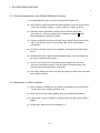
(4) Wiring
CAUTION
Correctly and securely wire the wires. Reconfirm the connections for mistakes and the terminal
screws for tightness after wiring. Failing to do so may lead to run away of the servomotor.
After wiring, install the protective covers such as the terminal covers to the original positions.
Do not install a phase advancing capacitor, surge absorber or radio noise filter (option FR-BIF)
on the output side of the servo amplifier.
Correctly connect the output side (terminal U, V, W) and ground. Incorrect connections will lead
the servomotor to operate abnormally.
Do not connect a commercial power supply to the servomotor, as this may lead to trouble.
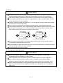
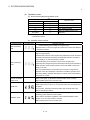
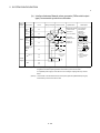
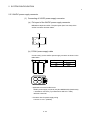
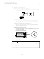
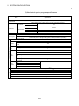
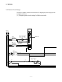
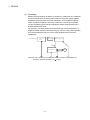
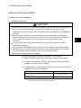
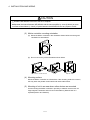
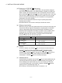
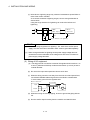
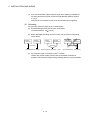
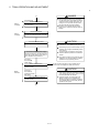
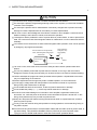
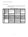
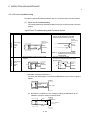
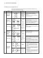
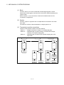
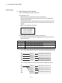
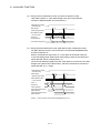
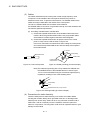
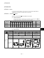
Do not mistake the direction of the surge absorbing diode installed on the DC relay for the control
signal output of brake signals, etc. Incorrect installation may lead to signals not being output
when trouble occurs or the protective functions not functioning.
Servo amplifier
DOCOM
Control output
signal
Servo amplifier
24VDC
DOCOM
Control output
signal
RA
DICOM
24VDC
RA
DICOM
For the sink output interface
For the source output interface
Do not connect or disconnect the connection cables between each unit, the encoder cable or
PLC expansion cable while the power is ON.
Securely tighten the cable connector fixing screws and fixing mechanisms. Insufficient fixing may
lead to the cables combing off during operation.
Do not bundle the power line or cables.
(5) Trial operation and adjustment
CAUTION
Confirm and adjust the program and each parameter before operation. Unpredictable
movements may occur depending on the machine.
Extreme adjustments and changes may lead to unstable operation, so never make them.
When using the absolute position system function, on starting up, and when the Motion
controller or absolute value motor has been replaced, always perform a home position return.
Before starting test operation, set the parameter speed limit value to the slowest value, and
make sure that operation can be stopped immediately by the forced stop, etc. if a hazardous
state occurs.
A-7
(6) Usage methods
CAUTION
Immediately turn OFF the power if smoke, abnormal sounds or odors are emitted from the
Motion controller, servo amplifier or servomotor.
Always execute a test operation before starting actual operations after the program or
parameters have been changed or after maintenance and inspection.
Do not attempt to disassemble and repair the units excluding a qualified technician whom our
company recognized.
Do not make any modifications to the unit.
Keep the effect or electromagnetic obstacles to a minimum by installing a noise filter or by using
wire shields, etc. Electromagnetic obstacles may affect the electronic devices used near the
Motion controller or servo amplifier.
When using the CE Mark-compliant equipment, refer to this manual for the Motion controllers
and refer to the corresponding EMC guideline information for the servo amplifiers, inverters and
other equipment.
Use the units with the following conditions.
Item
Conditions
Input power
According to each instruction manual.
Input frequency
According to each instruction manual.
Tolerable momentary power failure
According to each instruction manual.
(7) Corrective actions for errors
CAUTION
If an error occurs in the self diagnosis of the Motion controller or servo amplifier, confirm the
check details according to the instruction manual, and restore the operation.
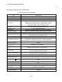
If a dangerous state is predicted in case of a power failure or product failure, use a servomotor
with electromagnetic brakes or install a brake mechanism externally.
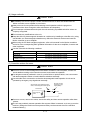
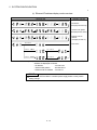
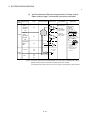
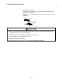
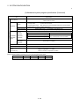
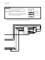
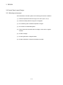
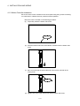
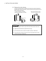
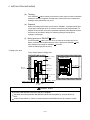
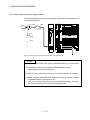
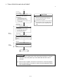
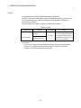
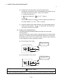
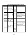
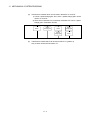
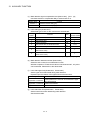
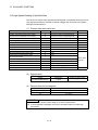
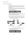
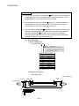
Use a double circuit construction so that the electromagnetic brake operation circuit can be
operated by emergency stop signals set externally.
Shut off with servo ON signal OFF,
alarm, electromagnetic brake signal.
Servomotor
RA1
Electromagnetic
brakes
Shut off with the
emergency stop
signal (EMG).
EMG
24VDC
If an error occurs, remove the cause, secure the safety and then resume operation after alarm
release.
The unit may suddenly resume operation after a power failure is restored, so do not go near the
machine. (Design the machine so that personal safety can be ensured even if the machine
restarts suddenly.)
A-8
(8) Maintenance, inspection and part replacement
CAUTION
Perform the daily and periodic inspections according to the instruction manual.
Perform maintenance and inspection after backing up the program and parameters for the Motion
controller and servo amplifier.
Do not place fingers or hands in the clearance when opening or closing any opening.
Periodically replace consumable parts such as batteries according to the instruction manual.
Do not touch the lead sections such as ICs or the connector contacts.
Before touching the module, always touch grounded metal, etc. to discharge static electricity from
human body. Failure to do so may cause the module to fail or malfunction.
Do not directly touch the module's conductive parts and electronic components.
Touching them could cause an operation failure or give damage to the module.
Do not place the Motion controller or servo amplifier on metal that may cause a power leakage
or wood, plastic or vinyl that may cause static electricity buildup.
Do not perform a megger test (insulation resistance measurement) during inspection.
When replacing the Motion controller or servo amplifier, always set the new module settings
correctly.
When the Motion controller or absolute value motor has been replaced, carry out a home
position return operation using one of the following methods, otherwise position displacement
could occur.
1) After writing the servo data to the Motion controller using programming software, switch on the
power again, then perform a home position return operation.
2) Using the backup function of the programming software, load the data backed up before
replacement.
After maintenance and inspections are completed, confirm that the position detection of the
absolute position detector function is correct.
Do not drop or impact the battery installed to the module.
Doing so may damage the battery, causing battery liquid to leak in the battery. Do not use the
dropped or impacted battery, but dispose of it.
Do not short circuit, charge, overheat, incinerate or disassemble the batteries.
The electrolytic capacitor will generate gas during a fault, so do not place your face near the
Motion controller or servo amplifier.
The electrolytic capacitor and fan will deteriorate. Periodically replace these to prevent secondary
damage from faults. Replacements can be made by our sales representative.
Lock the control panel and prevent access to those who are not certified to handle or install
electric equipment.
Do not burn or break a module and servo amplifier. Doing so may cause a toxic gas.
A-9
(9) About processing of waste
When you discard Motion controller, servo amplifier, a battery (primary battery) and other option
articles, please follow the law of each country (area).
CAUTION
This product is not designed or manufactured to be used in equipment or systems in situations
that can affect or endanger human life.
When considering this product for operation in special applications such as machinery or systems
used in passenger transportation, medical, aerospace, atomic power, electric power, or
submarine repeating applications, please contact your nearest Mitsubishi sales representative.
Although this product was manufactured under conditions of strict quality control, you are strongly
advised to install safety devices to forestall serious accidents when it is used in facilities where a
breakdown in the product is likely to cause a serious accident.
(10) General cautions
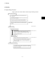
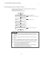
All drawings provided in the instruction manual show the state with the covers and safety
partitions removed to explain detailed sections. When operating the product, always return the
covers and partitions to the designated positions, and operate according to the instruction
manual.
A - 10
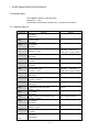
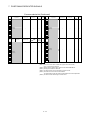
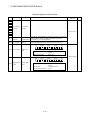
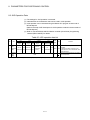
REVISIONS
The manual number is given on the bottom left of the back cover.
Print Date
Oct., 2008
Sep., 2009
July., 2010
Manual Number
Revision
IB(NA)-0300150-A First edition
IB(NA)-0300150-B [Additional correction/partial correction]
About manuals, EMC directive, Battery transportation, Symbol for the
new EU battery directive, MC protocol communication, Synchronous
encoder current value monitor in real mode, Connection of the servo
amplifier for direct drive motor
IB(NA)-0300150-C [Additional correction/partial correction]
Connection with GOT, Connection of the extension IO unit (MR-J3-D01)
April., 2011 IB(NA)-0300150-D [Additional correction/partial correction]
Postscript of MR-Configurator2
Dec., 2011
IB(NA)-0300150-E [Partial correction]
Section 4.2.1 Partial change of sentence
This manual confers no industrial property rights or any rights of any other kind, nor does it confer any patent
licenses. Mitsubishi Electric Corporation cannot be held responsible for any problems involving industrial property
rights which may occur as a result of using the contents noted in this manual.
© 2008 MITSUBISHI ELECTRIC CORPORATION
A - 11
INTRODUCTION
Thank you for choosing the Mitsubishi Motion controller MR-MQ100.
Before using the equipment, please read this manual carefully to develop full familiarity with the functions
and performance of the Motion controller you have purchased, so as to ensure correct use.
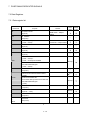
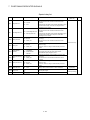
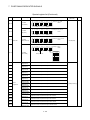
CONTENTS
Safety Precautions .......................................................................................................................................... A- 1
Revisions ......................................................................................................................................................... A-11
Contents .......................................................................................................................................................... A-12
About Manuals ................................................................................................................................................ A-16
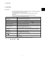
1. OVERVIEW
1- 1 to 1- 4
1.1 Overview.....................................................................................................................................................1- 1
1.2 Differences between MR-MQ100 and Q173DCPU/Q172DCPU .............................................................1- 3
1.3 Combination of software version and a function.......................................................................................1- 4
2. SYSTEM CONFIGURATION
2- 1 to 2-38
2.1 Motion System Configuration ....................................................................................................................2- 1
2.1.1 MR-MQ100 System overall configuration ..........................................................................................2- 3
2.1.2 Function explanation of the MR-MQ100 Motion controller ................................................................2- 4
2.1.3 Restrictions on Motion controller ........................................................................................................2- 4
2.2 Checking Serial Number............................................................................................................................2- 5
2.3 System Configuration Equipment..............................................................................................................2- 6
2.4 General Specifications ...............................................................................................................................2- 8
2.5 Specifications of Equipment and Settings.................................................................................................2- 9
2.5.1 Name of parts for MR-MQ100 ............................................................................................................2- 9
2.5.2 MR-MQ100 hardware and wiring....................................................................................................... 2-15
2.5.3 Connecting of 24VDC power supply connector of MR-MQ100........................................................ 2-24
2.5.4 SSCNET cables and connection method....................................................................................... 2-26
2.5.5 Battery ................................................................................................................................................ 2-29
2.5.6 Software specification of MR-MQ100................................................................................................ 2-34
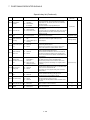
3. DESIGN
3- 1 to 3-10
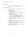
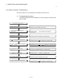
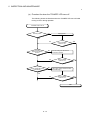
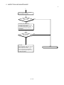
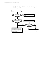
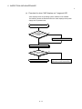
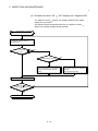
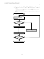
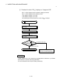
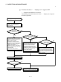
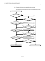
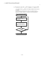
3.1 System Designing Procedure ....................................................................................................................3- 1
3.2 External Circuit Design ..............................................................................................................................3- 4
3.2.1 Power supply circuit design ................................................................................................................3- 6
3.2.2 Safety circuit design ............................................................................................................................3- 8
3.3 Layout Design within The Control Panel ...................................................................................................3- 9
3.3.1 Mounting environment ........................................................................................................................3- 9
3.3.2 Layout design of the Motion controller .............................................................................................. 3-10
3.3.3 Calculating heat generation by Motion controller.............................................................................. 3-11
3.4 Design Checklist ....................................................................................................................................... 3-11
A - 12
4. INSTALLATION AND WIRING
4- 1 to 4-16
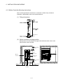
4.1 Motion controller Installation ......................................................................................................................4- 1
4.1.1 Instructions for handling ......................................................................................................................4- 1
4.1.2 Motion controller Installation ...............................................................................................................4- 2
4.1.3 Instructions for mounting the Motion controller ..................................................................................4- 3
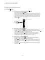
4.2 Connection and disconnection of Cable....................................................................................................4- 6
4.2.1 SSCNET cable .................................................................................................................................4- 6
4.2.2 24VDC power supply cable ............................................................................................................... 4-12
4.3 Wiring......................................................................................................................................................... 4-13
4.3.1 Instructions for wiring ......................................................................................................................... 4-13
4.3.2 Connecting to the power supply module ........................................................................................... 4-16
5. TRIAL OPERATION AND ADJUSTMENT
5- 1 to 5- 8
5.1 Checklist before Trial Operation ................................................................................................................55.2 Trial Operation and Adjustment Procedure...............................................................................................55.3 Operating System Software Installation Procedure..................................................................................55.4 Trial Operation and Adjustment Checklist.................................................................................................56. INSPECTION AND MAINTENANCE
1
2
6
7
6- 1 to 6-26
6.1 Maintenance Works ...................................................................................................................................6- 2
6.1.1 Instruction of Inspection works ...........................................................................................................6- 2
6.2 Daily Inspection ..........................................................................................................................................6- 4
6.3 Periodic Inspection.....................................................................................................................................6- 5
6.4 Life ..............................................................................................................................................................6- 6
6.5 Battery ........................................................................................................................................................6- 7
6.5.1 Battery life............................................................................................................................................6- 8
6.5.2 Battery replacement procedure ......................................................................................................... 6-10
6.5.3 Resuming operation after storing the Motion controller .................................................................... 6-11
6.5.4 Symbol for the new EU Battery Directive .......................................................................................... 6-11
6.6 Troubleshooting ........................................................................................................................................ 6-12
6.6.1 Troubleshooting basics ...................................................................................................................... 6-12
6.6.2 Troubleshooting of Motion CPU module ........................................................................................... 6-13
6.6.3 Confirming error code ........................................................................................................................ 6-24
6.6.4 I/O circuit troubleshooting .................................................................................................................. 6-25
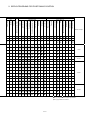
7. POSITIONING DEDICATED SIGNALS
7- 1 to 7-36
7.1 Device List ..................................................................................................................................................77.2 Internal relays ............................................................................................................................................77.2.1 Internal relay list ..................................................................................................................................77.2.2 Axis status list......................................................................................................................................77.2.3 Axis command signal list.....................................................................................................................77.2.4 Virtual servomotor axis status list .......................................................................................................77.2.5 Virtual servomotor axis command signal list ......................................................................................77.2.6 Synchronous encoder axis status list .................................................................................................7A - 13
1
2
2
4
5
6
7
8
7.2.7 Synchronous encoder axis command signal list................................................................................7- 8
7.2.8 Common device list.............................................................................................................................7- 9
7.2.9 Common device list (Command device) ........................................................................................... 7-12
7.3 Data Registers........................................................................................................................................... 7-13
7.3.1 Common device list (Command device) ........................................................................................... 7-13
7.3.2 Axis monitor device list....................................................................................................................... 7-15
7.3.3 Control change register list ................................................................................................................ 7-16
7.3.4 Virtual servomotor axis monitor device list ........................................................................................ 7-17
7.3.5 Synchronous encoder axis monitor device list.................................................................................. 7-18
7.3.6 Cam axis monitor device list .............................................................................................................. 7-18
7.3.7 Common device list............................................................................................................................ 7-19
7.4 Motion registers......................................................................................................................................... 7-20
7.4.1 Motion registers.................................................................................................................................. 7-20
7.4.2 Axis monitor device 2 ......................................................................................................................... 7-21
7.4.3 Motion error history devices............................................................................................................... 7-22
7.4.4 Mark detection area ........................................................................................................................... 7-23
7.4.5 Devices for extension IO unit............................................................................................................. 7-25
7.5 Special relays/Special registers................................................................................................................ 7-26
7.5.1 Special relays ..................................................................................................................................... 7-26
7.5.2 Special registers................................................................................................................................. 7-29
7.6 I/O devices................................................................................................................................................. 7-34
7.6.1 Input device list................................................................................................................................... 7-34
7.6.2 Output device list................................................................................................................................ 7-34
7.6.3 Input device ........................................................................................................................................ 7-35
7.6.4 Output device ..................................................................................................................................... 7-35
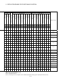
8. Parameters for positioning control
8- 1 to 8-8
8.1 Fixed Parameters.......................................................................................................................................88.2 Parameter Block.........................................................................................................................................88.3 JOG operation data....................................................................................................................................88.4 Home Position Return................................................................................................................................88.5 Servo Parameter ........................................................................................................................................89. SERVO PROGRAMS FOR POSITIONING CONTROL
1
2
4
5
8
9- 1 to 9-22
9.1 Servo Program Composition Area.............................................................................................................9- 1
9.1.1 Servo program composition................................................................................................................9- 1
9.1.2 Servo program area ............................................................................................................................9- 2
9.2 Servo Instructions ......................................................................................................................................9- 3
9.3 Positioning Data ........................................................................................................................................ 9-16
10. MOTION SFC PROGRAMS
10- 1 to 10-16
10.1 Motion SFC Performance Specifications ............................................................................................. 10- 1
10.2 Motion SFC Chart Symbol List ............................................................................................................. 10- 3
10.3 Branch and Coupling Chart List ........................................................................................................... 10- 6
10.4 Operation control/transition control specifications ............................................................................... 10-10
10.5 Program Parameters............................................................................................................................. 10-14
10.6 Device Descriptions .............................................................................................................................. 10-15
A - 14
11. MECHANICAL SYSTEM PROGRAM
11- 1 to 11-6
11.1 Mechanical Module Connection Diagram ............................................................................................ 11- 2
11.2 Mechanical Module List ........................................................................................................................ 11- 5
11.3 Device range ......................................................................................................................................... 11- 6
12. COMMUNICATION
12- 1 to 12-10
12.1 Connection to peripheral devices .......................................................................................................... 12- 1
12.1.1 Direct connection............................................................................................................................. 12- 1
12.1.2 Hub Connection .............................................................................................................................. 12- 4
12.1.3 Setting CPU name .......................................................................................................................... 12- 9
12.2 Connection with GOT ........................................................................................................................... 12-10
13. AUXILIARY FUNCTION
13- 1 to 13-20
13.1 Mark detection function......................................................................................................................... 13- 1
13.2 High-Speed Reading of Specified Data ............................................................................................... 13- 8
13.3 MC Protocol Communication................................................................................................................ 13- 9
13.4 Synchronous encoder for drive module ............................................................................................... 13-15
13.5 Connection of extension IO unit (MR-J3-D01)..................................................................................... 13-16
13.5.1 Connection of extension IO unit (MR-J3-D01) .............................................................................. 13-16
13.5.2 I/O devices...................................................................................................................................... 13-18
13.5.3 Related servo amplifier parameters .............................................................................................. 13-20
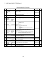
14. ERROR CODE
14- 1 to 14-4
14.1 Self-diagnosis errors ............................................................................................................................. 14- 1
14.2 System setting errors ............................................................................................................................ 14- 2
14.3 Servo program setting error.................................................................................................................. 14- 3
15. EMC DIRECTIVES
15- 1 to 15-8
15.1 Requirements for Compliance with the EMC Directive ....................................................................... 1515.1.1 Standards relevant to the EMC Directive ...................................................................................... 1515.1.2 Installation instructions for EMC Directive..................................................................................... 1515.1.3 Parts of measure against noise ..................................................................................................... 1515.1.4 Example of measure against noise ............................................................................................... 15APPENDICES
1
2
3
5
7
App- 1 to App-14
APPENDIX 1 Cables ..................................................................................................................................App- 1
APPENDIX 1.1 SSCNET cables..........................................................................................................App- 1
APPENDIX 1.2 24VDC power supply cable...........................................................................................App- 4
APPENDIX 1.3 Internal I/F connector cable...........................................................................................App- 5
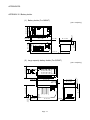
APPENDIX 2 Exterior Dimensions .............................................................................................................App-10
APPENDIX 2.1 MR-MQ100 ....................................................................................................................App-10
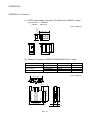
APPENDIX 2.2 Battery holder ................................................................................................................App-11
APPENDIX 2.3 Connector ......................................................................................................................App-12
A - 15
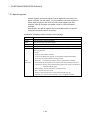
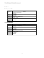
About Manuals
The following manuals are also related to this product.
If necessary, order them by quoting the details in the tables below.
Related Manuals
(1) Motion controller
Manual Number
(Model Code)
Manual Name
Q173DCPU/Q172DCPU Motion controller Programming Manual (COMMON)
This manual explains the Multiple CPU system configuration, performance specifications, common
parameters, auxiliary/applied functions, error lists and others.
IB-0300134
(1XB928)
(Optional)
Q173DCPU/Q172DCPU Motion controller (SV13/SV22) Programming Manual (Motion SFC)
This manual explains the functions, programming, debugging, error lists and others for Motion SFC.
IB-0300135
(1XB929)
(Optional)
Q173DCPU/Q172DCPU Motion controller (SV13/SV22) Programming Manual (REAL MODE)
This manual explains the servo parameters, positioning instructions, device lists, error lists and others.
IB-0300136
(1XB930)
(Optional)
Q173DCPU/Q172DCPU Motion controller (SV22) Programming Manual (VIRTUAL MODE)
This manual explains the dedicated instructions to use the synchronous control by virtual main shaft,
mechanical system program create mechanical module, servo parameters, positioning instructions, device
IB-0300137
(1XB931)
lists, error lists and others.
(Optional)
Motion Controller Setup Guidance(for MR-MQ100)
(MT Developer2 Version1)
IB-0300152
This manual describes those items related to the setup of the Motion controller programming software
MT Developer2 (for MR-MQ100).
A - 16
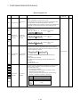
(2) Servo amplifier
Manual Number
(Model Code)
Manual Name
SSCNET
Compatible MR-J3- B Servo amplifier Instruction Manual
This manual explains the I/O signals, parts names, parameters, start-up procedure and others for
MR-J3- B Servo amplifier.
SH-030051
(1CW202)
(Optional)
SSCNET
Manual
interface 2-axis AC Servo Amplifier MR-J3W- B Servo amplifier Instruction
This manual explains the I/O signals, parts names, parameters, start-up procedure and others for 2-axis
SH-030073
(1CW604)
AC Servo Amplifier MR-J3W- B Servo amplifier.
(Optional)
SSCNET
Compatible Linear Servo MR-J3- B-RJ004 Instruction Manual
This manual explains the I/O signals, parts names, parameters, start-up procedure and others for Linear
Servo MR-J3- B-RJ004 Servo amplifier.
SH-030054
(1CW943)
(Optional)
SSCNET Compatible Fully Closed Loop Control MR-J3- B-RJ006 Servo amplifier
Instruction Manual
This manual explains the I/O signals, parts names, parameters, start-up procedure and others for Fully
SH-030056
(1CW304)
Closed Loop Control MR-J3- B-RJ006 Servo amplifier.
(Optional)
SSCNET
Manual
interface Drive Safety integrated MR-J3- B Safety Servo amplifier Instruction
This manual explains the I/O signals, parts names, parameters, start-up procedure and others for safety
integrated MR-J3- B Safety Servo amplifier.
(Optional)
A - 17
SH-030084
(1CW205)
MEMO
A - 18
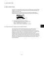
1 OVERVIEW
1. OVERVIEW
1
1.1 Overview
This User's Manual describes the hardware specifications, the software specifications
and handling methods of the Motion controller.
This manual explains the changes between the MR-MQ100 and Q173DCPU /
Q172DCPU.
Refer to the other motion controller manuals for details of each function.
In this manual, the following abbreviations are used.
Generic term/Abbreviation
MR-MQ100 or
Motion controller
Description
MR-MQ100 Single Axis Motion Controller
MR-J3- B
Servo amplifier model MR-J3- B
AMP or Servo amplifier
General name for "Servo amplifier model MR-J3- B "
Programming software package
General name for MT Developer2 /MR Configurator
Operating system software
General name for "SW9DNC-SV22QW"
SV22
Operating system software for automatic machinery : SW9DNC -SV22QW
Abbreviation for "Motion controller engineering environment
MELSOFT MT Works2 for MR-MQ100"
SW1DNC-MTW2MQ-E (Version 1.04E or later)
MELSOFT MT Works2
MT Developer2(Note-1)
MR Configurator
MR Configurator2
SSCNET
(Note-2)
Absolute position system
Abbreviation for "Motion controller programming software MT Developer2"
Abbreviation for "Servo setup software package
MR Configurator (Version C1 or later)"
Abbreviation for "Servo setup software package
MR Configurator2 (Version 1.00B or later)"
High speed synchronous network between Motion controller and servo
amplifier
General name for "system using the servomotor and servo amplifier for
absolute position"
(Note-1) : This software is included in Motion controller engineering environment "MELSOFT MT Works2"
(Note-2) : SSCNET: Servo System Controller NETwork
1-1
1 OVERVIEW
REMARK
For information about each module and design methods for programs and
parameters, refer to the following manuals.
Item
Reference Manual
Operation method for MT Developer2
Help of each software
• Performance specification
• Design method for common parameter
• Auxiliary and applied functions (common)
SV22
Q173DCPU/Q172DCPU Motion controller
Programming Manual (COMMON)
• Design method for Motion SFC program
Q173DCPU/Q172DCPU Motion controller (SV13/SV22)
• Design method for Motion SFC parameter
Programming Manual (Motion SFC)
• Design method for positioning control
program in the real mode
Q173DCPU/Q172DCPU Motion controller (SV13/SV22)
• Design method for positioning control
Programming Manual (REAL MODE)
parameter
SV22
(Virtual mode)
• Design method for mechanical system
program
Q173DCPU/Q172DCPU Motion controller (SV22)
Programming Manual (VIRTUAL MODE)
1-2
1 OVERVIEW
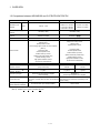
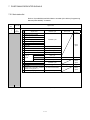
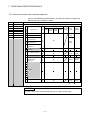
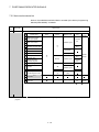
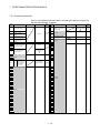
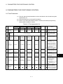
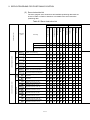
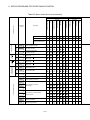
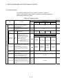
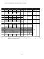
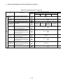
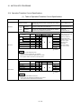
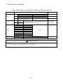
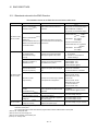
1.2 Comparison between MR-MQ100 and Q173DCPU/Q172DCPU
Items
MR-MQ100
Q173DCPU
Q172DCPU
0.44ms/ 1 to 4 axes
Operation cycle
(default)
SV22
0.44ms/ 1 axis
0.88ms/ 5 to 12 axes
0.44ms/ 1 to 4 axes
1.77ms/13 to 28 axes
0.88ms/ 5 to 8 axes
3.55ms/29 to 32 axes
Medium of operating system
CD-ROM (1 disk)
software
Model of operating system
CD-ROM (1 disk)
SW8DNC-SV Q
SW9DNC-SV22QW
software
Peripheral I/F
PERIPHRAL I/F
Via PLC CPU (USB/RS-232)
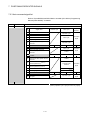
PTP(Point to Point) control,
Speed control,
Speed-position control
(The changing signal comes via servo amplifier)
PTP(Point to Point) control,
Speed control,
Speed-position control,
(Note-1),
Fixed-pitch feed,
Fixed-pitch feed,
Control modes
Constant speed control,
Position follow-up control,
Speed control with position stop,
Speed switching control,
High-speed oscillation control,
Synchronous control(SV22)
Constant speed control,
Position follow-up control,
Speed control with position stop,
Speed switching control,
High-speed oscillation control,
Synchronous control(SV22)
Manual pulse generator
Possible to connect 1 module
Synchronous encoder
Possible to connect 1 module
Possible to connect 12
Possible to connect 8
(Only incremental)
modules
modules
1 system
2 systems
1 system
operation function
Number of SSCNET
systems (Note-2)
External input signal
External input signal of servo amplifier
Q172DLX or
(FLS,RLS,DOG)
External input signal of servo amplifier
Servo amplifier has EM1 as the forced stop input.
Forced stop input
System Software Installation
• Use EMI terminal of Motion CPU module
(The motion controller does not have the forced stop • Use device set by forced stop input setting in the
input.)
Necessity of Operating
Possible to connect 3 modules
system setting.
No need to install. (It is already installed.)
Need to install
(Note-1) : "DOG" signal of servo amplifier is used as "Speed-position changing signal" of Speed-position control mode.
(Note-2) : SSCNET: Servo System Controller NETwork
1-3
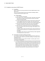
1 OVERVIEW
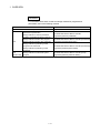
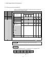
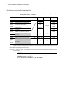
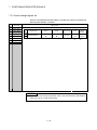
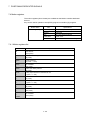
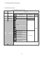
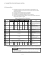
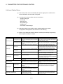
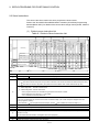
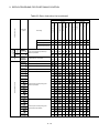
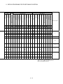
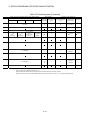
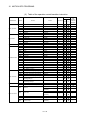
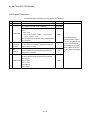
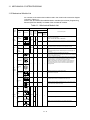
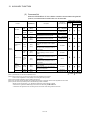
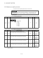
1.3 Combination of software version and a function
There are combination in the function that can be used by the version of the
operating system software and programming software.
The combination of each version and a function is shown below.
(1) Combination of software version and a function
Operating system
Function
Incremental synchronous encoder
current value in real mode
Connection of the servo amplifier for
direct drive motor
Connection with GOT by RS-422
communication
Connection of the extension IO unit
(MR-J3-D01)
version
Serial number of
(MELSOFT MT Works2)
Motion controller
00B
1.06G
-
Section 13.3
00B
-
-
Section 13.4
00B
1.06G
-
-
00C
-
G********
Section 12
00C
-
-
Section 13.5
software version
MC protocol communication
Section of
Programming software
reference
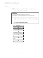
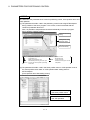
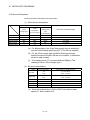
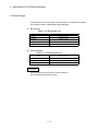
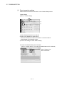
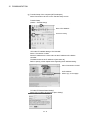
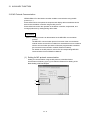
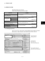
(2) Confirmation method of the operating system software's version
The operating system software's version of connected Motion controller is
displayed on the Operating system type item of the [Read from CPU ] screen in
MT Developer2.
Operating system software
S V 2 2 Q W
V
E
R
3
0
0
C
Version
1-4
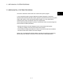
2 SYSTEM CONFIGURATION
2. SYSTEM CONFIGURATION
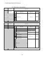
This section describes MR-MQ100 system configurations and usage precautions.
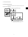
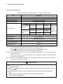
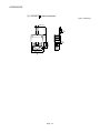
2.1 Motion System Configuration
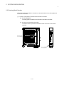
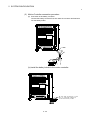
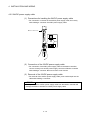
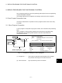
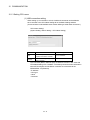
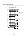
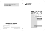
(1) Equipment configuration for MR-MQ100 system
(Note-1)
MITSUBISHI
LITHIUM BATTERY
Battery
(Q6BAT)
Motion controller
(MR-MQ100)
(Note-2)
M
L IT H
IT S U
I U
M
B
B
I S
A T T E R
H
I
Y
PROGRAMMABLE CONTROLLER PUSH
Q7BAT
SSCNETⅢ cable
(MR-J3BUS□M(-A/-B))
(Note-3)
PUSH
Large capacity
battery holder
(Q170MBAT-SET)
PUSH
TYPE
Servo amplifier
(MR-J3-□B)
Extension IO unit
(MR-J3-D01)
It is possible to select the best according to the system.
(Note-1): Be sure to install the Battery (Q6BAT) to the Battery holder.
(It is packed together with MR-MQ100.)
(Note-2): Large capacity battery use (Q7BAT is included), sold separately.
(Note-3): The extension IO unit has the limitation of the servo amplifier
that can be used. Refer to section 13.5 for details.
.
2-1
2
2 SYSTEM CONFIGURATION
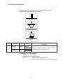
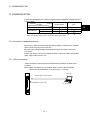
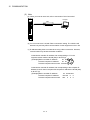
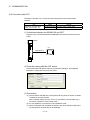
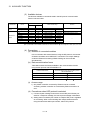
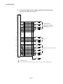
(2) Peripheral device configuration for the MR-MQ100 system
Peripheral connection options are shown below.
Motion controller
(MR-MQ100)
Ethernet cable
Computer
Part
Connection
Cable
Ethernet
name
type
type
standard
Ethernet
cable
Model name
Connection
Straight
10BASE-T
with HUB
cable
100BASE-TX
Compliant with Ethernet standards, category 5 or higher.
Direct
Crossover
10BASE-T
• Shielded twisted pair cable (STP cable)
connection
cable
100BASE-TX
(a) Selection criterion of cable
• Category
: 5 or higher
• Diameter of lead : AWG26 or higher
• Shield
: Copper braid shield and drain wire
Copper braid shield and aluminium layered type shield
2-2
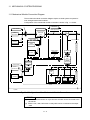
2 SYSTEM CONFIGURATION
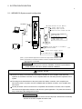
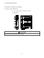
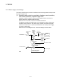
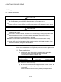
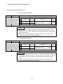
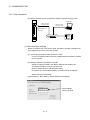
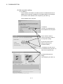
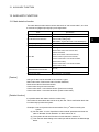
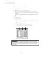
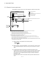
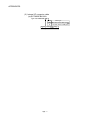
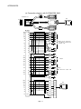
2.1.1 MR-MQ100 System overall configuration
PULL
PERIPHERAL I/F
MR-J3-D01 extension IO unit (Note-2)
d1
Analog input 2 points,
Analog output 2 points
Input 16 points, Output 16 points
External input signals of
servo amplifier
(Note-1)
M
E
24VDC
Proximity dog
Upper stroke limit
Lower stroke limit
MR-J3□B type
Servo amplifier
1 axis
P Manual pulse generator or Incremental
synchronous encoder
1 set
GOT
Input 4 points, Output 2 points
RS-422 communication I/F
GOT
(Note-1) Up to 16 different equipments can access to a single motion controller.
(Note-2) The extension IO unit has the limitation of the servo amplifier that can be used.
Refer to section 13.5 for details.
POINT
The latest operating system software "SW9DNC-SV22QW" is preinstalled in
the MR-MQ100. There is no need for customer installation.
CAUTION
Construct a safety circuit externally of the Motion controller or servo amplifier if the abnormal
operation of the Motion controller or servo amplifier differ from the safety directive operation in the
system.
The ratings and characteristics of the parts (other than Motion controller, servo amplifier and
servomotor) used in a system must be compatible with the Motion controller, servo amplifier and
servomotor.
Set the parameter values to those that are compatible with the Motion controller, servo amplifier,
servomotor and regenerative resistor model and the system application. The protective functions
may not function if the settings are incorrect.
Restriction matter
The Motion controller does not have a forced stop input, therefore the forced stop
function on the servo amplifier should be used.
2-3
2 SYSTEM CONFIGURATION
2.1.2 Function explanations of the MR-MQ100 Motion Controller
(1) Each MR-MQ100 system can control a single servo amplifier axis.
(2) The program is synchronized with the motion operation cycle and can be set to a
fixed cycle (0.44[ms], 0.88[ms], 1.77[ms], 3.55[ms], 7.11[ms], 14.2[ms]).
(3) Download of servo parameters, sending of servo ON/OFF and position
commands, etc. can be accomplished by connecting a SSCNET
cable
between MR-MQ100 and servo amplifier.
(4) A single incremental synchronous encoder can be used for synchronous control
with an external axis. Please note, hereafter, "INC" will be used instead of
"incremental ".
(5) The Motion controller uses the servo amplifier’s "stroke limit" and "DOG signal"
inputs.
(6) The MR-MQ100 has 4 digital inputs and 2 digital outputs. (The input signals can
be used as "Mark detection signals")
(7) RS-422 communication I/F functionality has been added to the internal I/F
connector of the Motion controller. This will enable connection with even the
GOTs that do not have Ethernet I/F connectivity.
(8) MR-J3-D01 extension IO unit for I/O signal, and analog I/O data can be controlled
by the Motion controller.
2.1.3 Restrictions on Motion controller
(1) Since the Motion controller does not contain a forced stop input, the forced stop
function of the servo amplifier should be used.
(2) Be sure to connect the battery (Q6BAT) which is included with MR-MQ100.
(3) It takes about 10 sec for the Motion controller to power up after 24VDC power is
applied.
(4) Set the rotary switch on the servo amplifier to "0".
2-4
2 SYSTEM CONFIGURATION
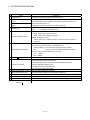
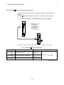
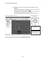
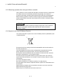
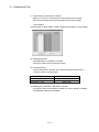
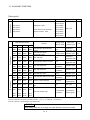
2.2 Checking Serial Number
The serial number of the Motion controller can be viewed both on the rating plate and
the face of the module.
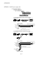
(1) Location of the Motion Controller serial number information.
(a) On the rating plate
The rating plate is located on the left side of the Motion controller.
(b) On the face of the Motion Controller
The serial number is printed on the bottom area of the face of the motion
controller.
PULL
Rating plate
Serial number
MITSUBISHI
MOTION CONTROLLER
MODEL
SERIAL
C
UL
PASSED
Q170MCPU
B8Y054306
80M1
US LISTED
IND. CONT. EQ
MITSUBISHI ELECTRIC JAPAN
Serial number
display plate
2-5
2 SYSTEM CONFIGURATION
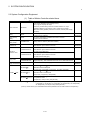
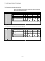
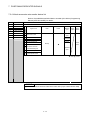
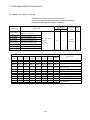
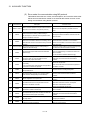
2.3 System Configuration Equipment
(1) Table of Motion Controller related items
Item
Model name
(Note-1)
Description
Remark
1 axis control, Operation cycle 0.44[ms] or more,
Servo program capacity 16k steps,
Motion controller
Internal I/F (Incremental synchronous encoder interface 1ch, Input
MR-MQ100
signal/Mark detection input signal 4 points, Output signal 2 points)
(Attachment battery (Q6BAT), Internal I/F connector , 24VDC power supply
connector)
Battery
Q6BAT
Large capacity
battery
Large capacity
battery holder
Internal I/F
connector set
For memory data backup of SRAM built-in Motion controller
included with
Nominal current: 1800mAh
MR-MQ100
For memory data backup of SRAM built-in Motion controller
Q7BAT
Nominal current: 5000mAh
Q170MBAT-SET
Battery holder for Q7BAT (Attachment Q7BAT)
Q170MIOCON
Incremental synchronous encoder ,
included with
Mark detection signal interface connector
MR-MQ100
Incremental synchronous encoder ,
Q170MIOCBL1M-A
Internal I/F
Mark detection signal interface connector
The GOT side is pigtail cable.
connector cable
Incremental synchronous encoder ,
Q170MIOCBL1M-B
Mark detection signal interface connector
24VDC power
Q170MPWCBL2M
Length 2m(6.56ft.), With solderless terminal R1.25-3.5
supply cable
Q170MPWCBL2M-E
Length 2m(6.56ft.), With solderless terminal R1.25-3.5, With EMI terminal
Q170MPWCON
Connector for 24VDC power supply cable
The GOT side is D-SUB (9pin).
24VDC power
supply connector set
• MR-MQ100
MR-J3BUS M
included with
MR-MQ100
MR-J3- B
• Standard code for inside panel
• 0.15m(0.49ft.), 0.3m(0.98ft.), 0.5m(1.64ft.), 1m(3,28ft.), 3m(9.84ft.)
• MR-MQ100
SSCNET
cable
MR-J3BUS M-A
MR-J3- B
• Standard cable for outside panel
• 5m(16.40ft.), 10m(32.81ft.), 20m(65.62ft.)
• MR-MQ100
MR-J3BUS M-B
(Note-2)
MR-J3- B
• Long distance cable
• 30m(98.43ft.), 40m(131.23ft.), 50m(164.04ft.)
(Note-1) :
=Cable length (015: 0.15m(0.49ft.), 03: 0.3m(0.98ft.), 05: 0.5m(1.64ft.), 1: 1m(3.28ft.), 2: 2m(6.56ft.),
3: 3m(9.84ft.), 5: 5m(16.40ft.), 10: 10m(32.81ft.), 20: 20m(65.62ft.), 25: 25m(82.02ft.),
30: 30m(98.43ft.), 40: 40m(131.23ft.), 50:50m(164.04ft.)
(Note-2) : Please contact your nearest Mitsubishi sales representative for the cable of less than 30m(98.43ft.).
2-6
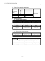
2 SYSTEM CONFIGURATION
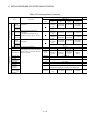
(2) Table of Servo amplifier related items
Item
Model name
Description
Remark
MR-J3- B
MR-J3 series servo
amplifier
MR-J3- B-RJ004
For linear servo motor
MR-J3- B-RJ006
For fully closed control
MR-J3- B-RJ080W For direct drive motor
Refer to the servo amplifier
MR-J3- S
For safety servo
instruction manuals.
Extension IO unit
MR-J3-D01
For I/O signal, analog I/O data
Battery
MR-J3BAT
Back-up for the absolute position
detection
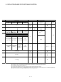
(3) Software packages
(a) Operating system software
Application
Model name
Medium
For automatic machinery SV22
SW9DNC-SV22QW
CD-ROM (1 disk)
(b) Motion controller engineering environment
Part name
Model name
Medium
SW1DNC-MTW2MQ-E
CD-ROM (1 disk)
MELSOFT MT Works2
for MR-MQ100
(MT Developer2
(Note-1)
)
(Note-1) : This software is included in Motion controller engineering environment "MELSOFT MT Works2".
(c) Servo set up software package
Part name
Model name
Details
MR Configurator
MRZJW3-SETUP221E
Version C1 or later
MR Configurator2
SW1DNC-MRC2-E
Version 1.00B or later
POINT
(1) When operating this software, if the operation of Windows is unclear, please
refer to a Windows manual or guide-book from another supplier.
(2) Use "standard size font" setting in Windows. When using the "Big font", setting
the display might not be shown properly.
2-7
2 SYSTEM CONFIGURATION
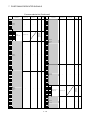
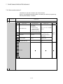
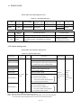
2.4 General Specifications
General specifications of MR-MQ100 Motion Controller are shown below.
Item
Specification
Operating ambient temperature
0 to 55°C (32 to 131°F)
-25 to 75°C (-13 to 167°F) (Note-3)
Storage ambient temperature
Operating ambient humidity
5 to 95% RH, non-condensing
Storage ambient humidity
5 to 95% RH, non-condensing
Under intermittent
vibration
Vibration resistance
Acceleration
5 to 9Hz
——
9 to 150Hz
Under continuous
vibration
Frequency
5 to 9Hz
Sweep count
3.5mm
(0.14inch)
2
9.8m/s
——
9 to 150Hz
Amplitude
2
4.9m/s
10 times each
——
in X, Y, Z
1.75mm
directions
(0.07inch)
(For 80 min.)
——
2
Shock resistance
147m/s , 3 times in each of 3 directions X, Y, Z
Operating ambience
No corrosive gases
Operating altitude
2000m(6561.68ft.) or less
Mounting location
Inside control panel
Overvoltage category (Note-1)
II or less
Pollution level (Note-2)
2 or less
(Note-1) : This indicates the section of the power supply to which the equipment is assumed to be connected between the
public electrical power distribution network and the machinery within premises.
Category
applies to equipment for which electrical power is supplied from fixed facilities.
The surge voltage withstand level for up to the rated voltage of 300V is 2500V.
(Note-2) : This index indicates the degree to which conductive material is generated in terms of the environment in which
the equipment is used.
Pollution level 2 is when only non-conductive pollution occurs. A temporary conductivity caused by condensing
must be expected occasionally.
(Note-3) : Do not use or store the Motion controller under pressure higher than the atmospheric pressure of altitude 0m.
Doing so can cause an operation failure.
CAUTION
The Motion controller must be stored and used under the conditions listed in the table of
specifications above.
When not using the module for a long time, disconnect the power line from the Motion controller
or servo amplifier.
Place the Motion controller and servo amplifier in static electricity preventing vinyl bags and
store.
When storing for a long time, please contact with our sales representative.
Also, execute a trial operation.
2-8
2 SYSTEM CONFIGURATION
2.5 Specifications of Equipment and Settings
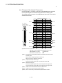
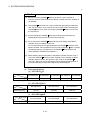
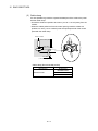
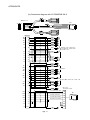
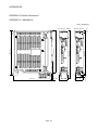
2.5.1 Name of parts for MR-MQ100
This section explains the names and settings of the module.
(1) MR-MQ100
11)
1)
2)
4)
3)
5)
6)
7)
8)
9)
10)
12)
CAUTION
Close the clear cover, after using the rotary switches.
2-9
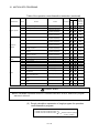
2 SYSTEM CONFIGURATION
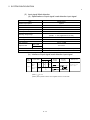
No.
Name
Application
1) 7-segment LED
• Indicates the operating status and error information.
Rotary function select 1 switch
2)
• Set the operation mode.
(Normal operation mode, Installation mode, Mode operated by ROM, etc)
(SW1)
Rotary function select 2 switch
• Each switch setting is 0 to F.
(Shipped from the factory in SW1 "0", SW2 "0" position)
(SW2)
• ON (Red) : The internal power (5VDC) is on.
3) POWER LED
• OFF
: The internal power (5VDC) is off.
• Move to RUN/STOP
RUN : Motion SFC program is started.
4) RUN/STOP/RESET switch
STOP : Motion SFC program is stopped.
•RESET (Momentary switch)
Set the switch to the "RESET" position 1 second or more to reset the
hardware.
• For communication I/F with peripherals. (Ethernet connector)
• The upper LED of the connector for PERIPHERAL I/F.
Remains flashing : It communicates with the personal computer.
5) PERIPHERAL I/F connector
OFF
: It doesn't communicate with the personal computer.
•The lower LED of the PERIPHERAL I/F connector
ON : 100Mbps
OFF : 10Mbps
6) SSCNET connector
(Note-1)
Connector to connect the servo amplifier
• Incremental synchronous encoder input.
Incremental synchronous encoder input has Differential-output type,
7) Internal I/F connector
Voltage-output/Open-collector type.
• The signal is input, the signal is output.
• RS-422 communication I/F for GOT
8) 24VDC power supply connector •The DC power of 24VDC is connected.
9) Serial number display plate
•The serial number written on the rating plate is displayed.
10) Battery holder
•Battery holder to set the Q6BAT/ Q7BAT
11) Hole for module fixing screw
Screw used to fix to the control box. (M5 screw)
12) FG terminal (Terminal for earth)
Earth terminal which is connected to shield patterns on the print circuit board.
(Note-1) : Refer to "2.5.4 SSCNET
cable and connection" about a notification and a method of connection for
SSCNET .
2 - 10
2 SYSTEM CONFIGURATION
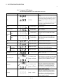
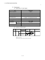
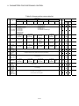
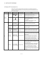
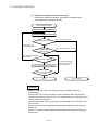
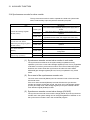
(2) 7-segment LED display
The LED displays/flashes in the combination with errors.
Item
7-segment LED
Remark
It takes about 10 seconds to initialize (RUN/STOP
display).
Execute the power cycle of the Motion controller
if the operation stopped at initializing. It may be
Start
Initializing
Motion controller's hardware fault when it is not
improved.
Explain the error symptom (LED display) and get
advice from our sales representative for the
modules with failure.
Normal
"
Installation mode
Mode operated by
RAM
" remains flashing
Steady "INS" display,
"
" remains flashing
"
" remains flashing
Mode for installing operating system software via
personal computer.
Mode for operating based on user programs and
parameters stored in the SRAM built-in Motion
controller.
Operation
mode
Normal operation
Mode for operating after the user programs and
Mode operated by
Steady "INS" display,
ROM
"
" remains flashing
parameters stored in the FLASH ROM built-in
Motion controller are read to the SRAM built-in
Motion controller.
STOP
Steady "STP" display
Stopped the Motion SFC program.
RUN
Steady "RUN" display
Executed the Motion SFC program.
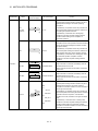
Early stage warning
Battery
(2.7V or less)
error
Final stage warning
(2.5V or less)
Operating system software
not installed
Steady "BT1" display
Steady "BT2" display
"A00" remains flashing
" AL" flashes 3 times
System setting error
Displayed at battery voltage 2.7V or less.
Refer to Section "6.5 External Battery".
Displayed at battery voltage 2.5V or less.
Refer to Section "6.5 External Battery".
Installation status mode when the operating system
software is not installed.
System setting error of the Motion controller Refer
to the "Q173DCPU/Q172DCPU Motion controller
Steady " L01" display
Programming Manual (COMMON)" for details.
Motion controller servo error.
" AL" flashes 3 times
Servo error
Steady " S01" display
Refer to the "Q173DCPU/Q172DCPU Motion
controller (SV13/SV22) Programming Manual
(REAL MODE)" or "Q173DCPU/Q172DCPU
Motion controller (SV22) Programming Manual
(VIRTUAL MODE)" for details.
Hardware fault or software fault
Refer to the "Q173DCPU/Q172DCPU Motion
WDT error
Steady "..." display
controller (SV13/SV22) Programming Manual
(REAL MODE)" or "Q173DCPU/Q172DCPU
Motion controller (SV22) Programming Manual
(VIRTUAL MODE)" for details.
2 - 11
2 SYSTEM CONFIGURATION
POINT
(1) When an error is displayed on the 7-segment LED, confirm the error number
etc. using MT Developer2.
(2) Refer to the Motion controller error batch monitor of MT Developer2 or error list
of the programming manual for error details.
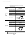
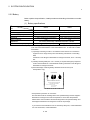
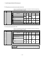
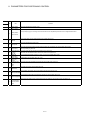
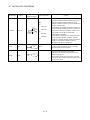
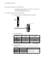
(3) Rotary switch assignment
(a) Rotary function select switch 1 (SW1)
Rotary switch
(Note)
Mode
0
Normal mode
A
Installation mode
Description
Normal operation mode
4 56
CD
AB E
23
F0 1
Setting
When installing the operating system software
using MT Developer2
789
(Note): Should not be set to anything except the above settings.
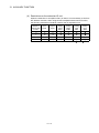
(b) Rotary function select switch 2 (SW2)
Rotary switch
Setting
(Note)
Mode
Description
Normal operation mode
0
Mode operated by RAM
(Operation by the setting data and parameters
stored in the Motion controller’s SRAM.)
Mode to operate based on the setting data and
23
4 56
CD
AB E
F0 1
6
Mode operated by ROM
the parameters written to the Motion controller’s
FLASH ROM.
789
8
C
Ethernet IP address
display mode
SRAM clear
Ethernet Internet Protocol address display mode.
SRAM "0" clear
(Note): Not to be set except above setting.
CAUTION
Be sure to turn OFF the Motion controller power supply before the rotary switch setting
change.
2 - 12
2 SYSTEM CONFIGURATION
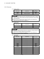
(4) Operation mode
(a) Rotary switch setting and operation mode
Rotary switch setting (Note)
SW1
A
Operation mode
SW2
Any setting (Except C) Installation mode
0
0
Mode operated by RAM
0
6
Mode operated by ROM
0
8
Ethernet IP address display mode
Any setting
C
SRAM clear (Note)
(Note) : The programs, parameters, absolute position data, and latch data built-in Motion
controller are cleared.
(b) Operation mode overview
Operation mode
7-segment LED
Operation overview
• " . " remains flashing in the first digit of 7-segment LED.
Mode operated by
• Operates based on the user program and parameters stored in the SRAM of
RAM
the Motion controller.
• " . " remains flashing in the first digit and steady " . " display in the second
digit of 7-segment LED.
• Operation starts after the user programs and parameters stored in the Motion
controller’s FLASH ROM are read to the SRAM built-in Motion controller at
power supply on or reset of the Motion controller.
If the ROM writing is not executed, even if the user programs and
Mode operated by
parameters are changed using the MT Developer2 during mode operated by
ROM
ROM, operation starts with the contents of the FLASH ROM at next power
supply on or reset.
Also, If the ROM writing is not executed, even if the auto tuning data are
reflected on the servo parameter of the Motion controller by operation in the
auto-tuning setting, operation starts with the contents of the FLASH ROM at
next power on or reset.
Ethernet IP address
display mode
-
• Refer to next page "(c) Ethernet IP address display mode overview".
• Digital oscilloscope function cannot be used.
• " . " remains flashing in the first digit and steady.
• When rotary switch 2 is set to "C", and a power ON is done, the SRAM area
SRAM clear
is cleared.
• The programs, parameters, absolute position data, and latch data in the
Motion controller are cleared.
• Steady "INS" display at the 7-segment LED.
• Operating system software can be installed.
Installation mode
• STOP status is maintained regardless of the RUN/STOP/RESET switch
position on the front side of Motion controller.
• Digital oscilloscope function cannot be used.
2 - 13
2 SYSTEM CONFIGURATION
(c) Ethernet IP address display mode overview
7-segment LED
Operation overview
• IP address
Example(192.168.3.39)
• Subnet mask pattern
Example(255.255.255.0)
• Default router IP
address
Example(192.168.3.1)
Disconnect
• Link status
Connect (10Mbps)
Full duplex
Connect (100Mbps)
Half duplex
(Note): When the Ethernet parameters are not written in the Motion controller , the
address are displayed as follows.
• IP address
: 192.168.3.39
• Subnet mask pattern
: 255.255.255.0
• Default router IP address : 192.168.3.1
POINT
Be sure to turn OFF the Motion controller power supply before a rotary switch
setting change.
2 - 14
2 SYSTEM CONFIGURATION
2.5.2 MR-MQ100 hardware and wiring
(1) Module specification
(a) Module specification
Item
24VDC
power supply
Specifications
Input voltage (Note-1), (Note-2)
Inrush current (Note-3)
Max. input current
21.6 to 26.4VDC
(24VDC +/-10%, ripple ratio 5% or less)
100A 1ms or less (at 24VDC input)
0.69A
Efficiency
80% (TYP.)
Input type
connector
Power consumption
16.6W
Permissible instantaneous power off time
(Note-4), (Note-5)
Mass
10ms (at 24VDC input)
0.7kg
178 (H) × 30(W) × 135(D)mm
Exterior dimensions
(Note-6)
(7.01(H) × 1.18(W) × 5.31(D) )inch
Installation method
It fixes directly to the control panel.
POINT
(Note-1) : Input power supply
MR-MQ100 is rated for use with a 24VDC input power supply only. The
MR-MQ100 unit breaks down when 28VDC or more is input.
(Note-2) : Select 24VDC power supply and electric wire within the range of
21.6 to 26.4VDC including any input ripple or spike voltage measured at
the input connector of the MR-MQ100.
(Note-3) : Inrush current
Take care that the inrush current of several amperes may flow when
the sharp square voltage is applied, or the power supply is turned ON
with the mechanical switch.
Turn on the primary(AC side) of power supply.
When selecting a fuse and breaker in the external circuit, take account of
the blow-out, detection characteristics and above points.
(Note-4) : Allowable momentary power failure period
(a) An instantaneous power failure lasting less than 10ms(Note) will cause
24VDC down to be detected, but operation will continue.
(b) An instantaneous power failure lasting in excess of 10ms(Note) may
cause the operation to continue or initial start to take place depending
on the power supply load.
(Note) : This is for a 24VDC input. This is 10ms or less for less than
24VDC.
(Note-5) : Select 24VDC power supply with allowable momentary power failure
period of 20ms or more .
(Note-6) : Exterior dimensions
The stated height (H) of the MR-MQ100 does include the battery holder
dimensions.
2 - 15
2 SYSTEM CONFIGURATION
(b) Pin layout of the Internal I/F connector
Use the internal I/F connector on the front of the MR-MQ100 to connect to
manual pulse signals and incremental synchronous encoder signals.
The following is the pin layout of the MR-MQ100's internal I/F connector as
viewed from the front.
(Note-1)
Pin layout
on the side of
printed circuit board
50
25
(Note-6)
(Note-5)
26
1
(Note-4)
(Note-6)
PIN No.
50
49
48
47
46
45
44
43
42
41
40
39
38
37
36
35
34
33
32
31
30
29
28
27
26
Internal I/F connector
Signal name PIN No. Signal name
SG
25
HBL
24
HBH
SEL
SG
23
HAL
SG
HAH
22
5V
21
HB
5V
20
HA
No connect
19
No connect
No connect
18
No connect
17
TXDL
RXDL
16
TXDH
RXDH
15
No connect
No connect
14
No connect
No connect
13
AB
SG
12
No connect
SG
11
No connect
No connect
10
No connect
No connect
9
No connect
No connect
8
No connect
No connect
7
COM2
COM2
6
DO2
DO1
5
COM1
COM1
4
DI4
DI3
3
DI2
DI1
2
No connect
No connect
1
No connect
No connect
(Note-3)
(Note-2)
(Note-6)
(Note-5)
(Note-4)
(Note-6)
Applicable connector model name
HDR type connector (HONDA TSUSHIN KOGYO CO. LTD)
HDR-E50MSG1+ connector
(Attachment)
HDR-E50LPH connector case
(Note-1) : Input type from manual pulse generator/ Incremental synchronous encoder
switched by SEL .
Not connected: Voltage-output/open-collector type.
SEL-SG connection : Differential -output type.
(Note-2) : Voltage-output/open-collector type
Connect the A-phase signal to HA, and the B-phase signal to HB.
(Note-3) : Differential-output type
Connect the A-phase signal to HAH, and the A-phase inverse signal HAL.
Connect the B-phase signal to HBH, and the B-phase inverse signal HBL.
(Note-4) : "COM1" is the common terminal of DI1, DI2, DI3 and DI4.
(Note-5) : "COM2" is the common terminal of DO1 and DO2.
(Note-6) : Do not connect to any of the terminal is explained as "No connect ".
2 - 16
2 SYSTEM CONFIGURATION
(2) Input signal/ Mark detection
(a) Specifications of input signal/ mark detection input signal
Item
Specifications
Number of input points
4 points
Input method
Positive common/ Negative common shared
Isolation method
Photo coupler
Rated input voltage
24VDC
Rated input current (IIN)
Approx.5mA
21.6 to 26.4VDC
Operating voltage range
(24VDC +/ -10%, ripple ratio 5% or less)
ON voltage/current
17.5VDC or more/3.5mA or more
OFF voltage/current
5VDC or less/0.9mA or less
Input resistance
Approx. 5.6k
OFF to ON
Response time
1ms or less
ON to OFF
Common terminal arrangement
4 points/common(Common contact: COM1)
Indicates to display
None
(b) Interface of input signal/ mark detection input signal
Pin No.
Input or
output
Signal name
Input
Input/
DI□
Note-1
Mark
detection
input
COM1
(Note-1) :
DI1 DI2 DI3 DI4
3
28
4
5
30
Wiring
example
Internal
circuit
Description
Signal input,
Mark detection
signal input
29
+ -
24VDC
Note-2
=1 to 4
(Note-2) : Both "positive common" and "negative common" can be used.
2 - 17
2 SYSTEM CONFIGURATION
(3) Output signal
(a) Specification of output signal
Item
Specifications
Number of output points
2 points
Output method
Sink/Source type
Isolation method
Photo coupler
Rated load voltage
24VDC +/ -10%
Maximum load current (lout)
40mA/point, 80mA/common
21.6 to 26.4VDC
External supply power
(24VDC +/ -10%, ripple ratio 5% or less)
Maximum voltage drop at ON (Vdorp)
2.75VDC or less
OFF voltage/ current
11VDC or less/ 1.7mA or less
Input resistance
Approx. 5.6k
Response time
OFF to ON
1ms or less
ON to OFF
1ms or less(Rated load, resistance load)
Common terminal arrangement
2 points/common(Common contact: COM2)
Indicates to display
None
(b) Interface of output signal
Input or
output
Signal name
Pin No.
DO1
DO2
Wiring
example
6
31
Load
Internal circuit
Description
Signal output
D0□
Output
Output
Note-1
COM2
(Note-1) :
7
32
24VDC
Note-2
= 1 to 2
(Note-2) : Both "sink type" and "source type" can be used.
2 - 18
2 SYSTEM CONFIGURATION
(4) Manual pulse generator/ Incremental synchronous encoder input
(a) Specification of manual pulse generator/ Incremental
synchronous encoder
Item
Specifications
Signal input form
Phase A/ Phase B
Maximum input pulse frequency
1Mpps
(After magnification by 4, up to 4Mpps)
Pulse width
1 µs or more
Leading edge/trailing edge time
0.25µs or less
Phase difference
0.25µs or more
High-voltage
2.0 to 5.25 VDC
Low-voltage
0 to 0.8 VDC
Differential-output Differential voltage
type
Adjustment type
(26LS31 or
Cable length
-0.2 to 0.2 V
Differential-output type(26LS31 or equivalent)
30m (98.43ft.)
equivalent)
1μs
0.5μs
Phase A
0.5μs
0.25μs
Example of waveform
Phase B
0.25μs
0.25μs
Duty ratio 50%
Maximum input pulse frequency
200kpps
(After magnification by 4, up to 800kpps)
Pulse width
5µs or more
Leading edge/trailing edge time
1.2µs or less
Phase difference
1.2µs or more
High-voltage
3.0 to 5.25 VDC
Low-voltage
0 to 1 VDC
Adjustment type
Voltage-output/
Open-collector type
Voltage-output/ Open-collector type(5VDC)
Cable length
10m (32.8ft.)
5μs
2.5μs
Phase A
2.5μs
1.2μs
Example of waveform
Phase B
1.2μs
1.2μs
Duty ratio 50%
POINT
Use a manual pulse generator or an incremental synchronous encoder that
consumes less than 0.2[A] of current.
2 - 19
2 SYSTEM CONFIGURATION
(b) Interface between Manual pulse generator (Differential-output
type)/ Incremental synchronous encoder
Input or
Signal name
Output
A
Manual
HAH
pulse
generator,
A
phase A
HAL
B
Input
Manual
HBH
pulse
generator,
B
phase B
HBL
Pin No.
22
24
Manual pulse
generator/
INC
synchronous
encoder
Description
For connection
manual pulse
generator
Phases A, B
Pulse width
1 s or more
LOW level
0.8VDC or less
B
0.5 s
or more
0.5 s
or more
(Duty ratio: 50% 25%)
26LS31 or
equivalent
25
Leading edge, Trailing
edge time 0.25 s or less.
Phase difference
Phase A
(Note-1)
45
Phase B
(Note-2)
5V
46
Power supply
5VDC
0.25 s or
more
(1) Address increases
if Phase A leads
Phase B.
(2) Address decreases
if Phase B leads
Phase A.
SG
47
SG
HIGH level
2.0 to 5.25VDC
B
49
Power
supply
Specification
Rated input voltage
5.5VDC or less
A
A
23
Select type
signal
SEL
5V
Wiring example Internal circuit
48
50
(Note-1) : The 5VDC power supply from the MR-MQ100 must not be used if a separate power supply
is applied to the Manual pulse generator/ incremental synchronous encoder.
If a separate power supply is used, be sure it is 5V voltage. Anything else may cause a
failure.
(Note-2) : Connect SEL to the SG terminal if the manual pulse generator (differential-output type)/
incremental synchronous encoder is used.
2 - 20
2 SYSTEM CONFIGURATION
(c) Interface between Manual pulse generator (Voltage-output/
Open-collector type)/ Incremental synchronous encoder
Input or
Signal name
Output
Manual
pulse
generator,
phase A
Pin No.
20
Manual
pulse
generator,
phase B
HIGH level
3 to 5.25VDC/
2mA or less
Manual pulse
generator/
Incremental
synchronous
encoder
B
LOW level
1VDC or less/
5mA or more
21
HB
Description
Specification
Rated input voltage
5.5VDC or less
A
HA
Input
Wiring example Internal circuit
For connection
manual pulse
generator
Phases A, B
Pulse width
5 s or more
2.5 s
or more
2.5 s
or more
(Duty ratio: 50% 25%)
Leading edge, Trailing
edge time 1.2 s or less.
Phase difference
Phase A
Select type
signal
SEL
(Note)
5V
Power
supply
SG
Phase B
49
45
46
47
48
50
No connect
5V
Power supply
5VDC
2.5 s or
more
(1) Address increases
if Phase A leads
Phase B.
(2) Address decreases
if Phase B leads
Phase A.
SG
(Note) : The 5VDC power supply from the MR-MQ100 must not be used if a separate power supply is
applied to the Manual pulse generator/ incremental synchronous encoder.
If a separate power supply is used, be sure it is 5V voltage. Anything else may cause a failure.
2 - 21
2 SYSTEM CONFIGURATION
(d) Connection examples of manual pulse generator/ incremental
synchronous encoder
Differential-output type
Voltage-output/ Open-collector type
Manual pulse
generator side/
Incremental synchronous
encoder side
MR-MQ100
Signal name
Manual pulse
generator side/
Incremental synchronous
encoder side
MR-MQ100
Signal name
HAH
A
HA
HAL
A
HB
B
HBH
B
SG
0V
HBL
B
SG
5V
SG
0V
SG
5V
5V
5V
SG
(Note-2)
(Note-1)
SEL
(Note-1)
FG(Shell)
SEL
FG(Shell)
A
Shield
:Twist pair cable
Shield
:Twist
pair cable
(Note-1) : The 5VDC power supply from the MR-MQ100 must not be used if a separate power supply is applied to the Manual
pulse generator/ incremental synchronous encoder.
If a separate power supply is used, be sure it is 5V stabilized. Anything else may cause a failure.
(Note-2) : Input type from manual pulse generator/incremental synchronous encoder switched by SEL.
Not connected: Voltage-output/open-collector type
SEL-SG connection: Difference-output type
CAUTION
If a separate power supply is used as the manual pulse generator/incremental synchronous
encoder power supply, use a 5V stabilized power supply. Any other power supply may cause a
failure.
Wiring during power-on may damage the unit. Power off the unit, before wiring.
Miss wiring may cause damage to the unit. Ensure care during wiring.
(5) PERIPHERAL I/F
Item
Specifications
Data transmission speed
Transmission
100/10Mbps
Communication mode
Full-duplex/ Half-duplex
Transmission method
Base band
Cable length [m(ft)]
Up to 30 (98.43)
2 - 22
2 SYSTEM CONFIGURATION
(6) RS-422 communication I/F
Item
Specifications
Communication mode
Full-duplex
Synchronous method
Asynchronous communication method
Data transmission speed
Data type
9600/ 19200/ 38400bps
Start bit
1
Data bit
8
Parity bit
Odd
Stop bit
1
Cable length [m(ft)]
Up to 30 (98.43)
2 - 23
2 SYSTEM CONFIGURATION
2.5.3 24VDC power supply connector
(1) Connecting of 24VDC power supply connector
(a) Pin layout of the 24VDC power supply connector
MR-MQ100 requires 24VDC. The pins layout (from front view) of the
24VDC connector is shown below.
24V(+)
24G
(b) DC24V power supply cable
Connect 24V(+) to the 24VDC power supply connector as shown in the
table below.
Pin No.
Signal Name
1B
2B
24V(+)
24G
• Applicable connector model name
24VDC power supply connector set (Q170MPWCON) (Attachment)
1-1827864-2 connector (Tyco Electronics AMP K.K. make)
1827587-2 terminal
• Conductor size for power supply wiring
0.34 to 0.37 mm2 (AWG22)
2 - 24
2 SYSTEM CONFIGURATION
• Termination of the cables
When the 24VDC power supply cable is produced with the customer, a
crimping tool is necessary.
Please refer to the manual of the manufacturing maker of the crimp tool
for details.
Sheath
Core
2mm +/-0.3mm
0.1 to 0.65mm
1827587-2 terminal
CAUTION
24V(+) pin is upper side and 24G pin is lower side of 24VDC connector of MR-MQ100. If the
polarity is wrong, the unit may be damaged.
Recommend the use of twisted pair cabling for 24VDC input.
Power off the unit before wiring 24VDC input.
Use proper size wire for 24VDC.
Do not connect to pins "1A" or "2A" of the 24VDC power input connector.
2 - 25
2 SYSTEM CONFIGURATION
2.5.4 SSCNET
cables and connection method
This section describes how to connect between the Motion controller and servo
amplifier.
SSCNET cabling is used between the Motion controller and servo amplifier.
(1) Connection between the MR-MQ100 and servo amplifier
PULL
SSCNETⅢ cable length
・ MR-J3BUS□M use
①≦3m(9.84ft)
・ MR-J3BUS□M-A use
①≦20m(65.62ft)
・ MR-J3BUS□M-B use
①≦50m(164.04ft)
CN1
①
CN1A
Cap
CN1B
Servo amplifier
(Note): Communication will not be possible if CN1A and CN1B are mistaken for one-another.
List of SSCNET
Model name
(Note)
MR-J3BUS M
cable model name
Description
Cable length
0.15m(0.49ft.), 0.3m(0.98ft.), 0.5m(1.64ft.),
Standard cord for
1m(3.28ft.), 3m(9.84ft.)
inside panel
Standard cable for
MR-J3BUS M-A
5m(16.4ft.), 10m(32.81ft.), 20m(65.62ft.)
MR-J3BUS M-B
30m(98.43ft.), 40m(131.23ft.), 50m(164.04ft.)
• MR-MQ100
MR-J3- B
outside panel
Long distance cable
(Note) :
2 - 26
=cable length
2 SYSTEM CONFIGURATION
POINT
(1) Be sure to connect SSCNET cable as per above. If the connection is
incorrect, communication between the Motion controller and servo amplifier is
not possible.
(2) The SSCNET connector has a cap to protect the optical device inside from
dust. For this reason, do not remove the cap until just before connecting the
SSCNET cable. Also, when removing the SSCNET cable, be sure to put
the cap back on.
(3) Be sure to keep the SSCNET fiber optic protective cap and tubing in a
sealed plastic bag to prevent them from becoming dirty.
(4) Do not remove the SSCNET cable while the power supply of the Motion
controller or servo amplifier is turned on.
Do not look directly into the light generated from SSCNET connector of the
Motion controller, servo amplifier or from the end of SSCNET cable. The light
can damage the eye. (The light source of SSCNET cable complies with
class1 defined in JISC6802 or IEC60825-1.)
(5) When replacing the servo amplifier or the Motion controller, be sure to put a
cap on the SSCNET connector. When sending a servo amplifier or Motion
controller back for repairs, also be sure to put a cap on the SSCNET
connector. Without a cap, the light device may be damaged during transit. If
this is the exchange or repair of the light device will be required.
(2) Cable specifications
(a) MR-J3BUS M
Model name
Item
Cable length [m(ft.)]
MR-J3BUS015M
MR-J3BUS03M
MR-J3BUS05M
MR-J3BUS1M
MR-J3BUS3M
0.15(0.49)
0.3(0.98)
0.5(1.64)
1(3.28)
3(9.84)
(b) MR-J3BUS M-A
Model name
Item
Cable length [m(ft.)]
MR-J3BUS5M-A
MR-J3BUS10M-A
MR-J3BUS20M-A
5(16.40)
10(32.81)
20(65.62)
MR-J3BUS30M-B
MR-J3BUS40M-B
MR-J3BUS50M-B
30(98.43)
40(131.23)
50(164.04)
(c) MR-J3BUS M-B
Model name
Item
Cable length [m(ft.)]
2 - 27
2 SYSTEM CONFIGURATION
(3) Setting of the axis No. and axis select rotary switch of servo
amplifier
Axis No. is used in the program to set the axis numbers of any servo amplifiers
connected to the motion controller via SSCNET .
Set the axis select rotary switch of the servo amplifier to "0", because the axis
number is fixed in the "system structure" display as "d01".
(The default setting of the axis select rotary switch of servo amplifier is "0".)
• System structure (Allocation of axis No.)
• Axis select rotary switch
(Servo amplifier)
B C DE
2
A
3 4 5 6
7 8 9
F 0 1
Set the servo amplifier’s
rotary switch to "0".
The axis number "d01"
is fixed on the "system
structure" display.
2 - 28
2 SYSTEM CONFIGURATION
2.5.5 Battery
Below explains the specification, install procedure and handling of the Motion controller
battery.
(1) Battery specifications
Model name
Q6BAT
Item
Classification
Q7BAT
Manganese dioxide lithium primary battery
Initial voltage [V]
3.0
Nominal current [mAh]
Storage life
1800
5000
5 years typical (Room temperature)
5 years typical (Room temperature)
0.49
1.52
Lithium content [g]
Applications
For memory data backup of SRAM built-in Motion controller
16(0.63)×32(1.26)
Exterior dimensions [mm(inch)]
24(0.94)×52(2.05)
(Note) : The following points are changed for lithium metal batteries transportation by sea
or air due to Recommendations of the United Nations Rev. 15 and ICAO-TI 20092010 edition.
1) A package containing 24 cells or 12 batteries or less that are not contained in
equipment are no longer exempt from the following: attachment of a handling
label,
submission of the Shipper's Declaration for Dangerous Goods, and a 1.2m drop
test.
2) A battery handling label (size: 120 x 110mm) is required. Emergency telephone
number must be filled out in the additional handling information of the Shipper's
Declaration for Dangerous Goods.
3) New label design containing battery illustration must be used (in air
transportation only).
CAUTION!
IF DAMAGED
Lithium Metal batteries
DO NOT LOAD OR TRANSPORT
PACKAGE IF DAMAGED
For more information,call
+81-3-3218-3639
International
Fig.2.1 Example of Label with Battery Illustration
• Transportation precaution for customers
Documentations like the handling label in the specified design and the Shipper's
Declaration for Dangerous Goods are required for air and sea transportation.
Please attach documentations like the handling label in the specified design and
the Shipper's Declaration for Dangerous Goods to the package.
If you need the self-certification form for the battery safety test, contact Mitsubishi.
For more information, contact Mitsubishi.
2 - 29
2 SYSTEM CONFIGURATION
(2) Data back-up of the Motion controller by the battery
Be sure to set the battery to the Motion controller.
Set the battery (Q6BAT/Q7BAT) to battery holder.
The data (Refer to Section 6.5.) of SRAM built-in Motion controller are backed
up without using the battery.
In the following status, the backup time after power OFF is 3 minutes.
• The Q6BAT/Q7BAT lead connector is disconnected.
• The lead wire of Q6BAT/Q7BAT is broken.
Battery life (Total power failure time) [h]
Battery type Power-on time
ratio (Note-2)
Battery
(Q6BAT)
Large
capacity
battery
(Q7BAT)
Guaranteed value
Guaranteed value
(Note-3)
(Note-4)
(MIN) (75°C (167°F)) (TYP) (40°C (104°F))
0%
20000
30%
27000
50%
31000
70%
36000
100%
43800
0%
39000
(Note-1)
Actual service value
(Note-5)
(Reference value)
Backup time after alarm
(TYP) (25°C (77°F))
43800
43800
43800
43800
90
(After SM51,SM52 ON)
30%
50%
70%
43800
90
(After SM51,SM52 ON)
100%
(Note-1) : The actual service value indicates the average value, and the guaranteed time indicates the minimum time.
(Note-2) : The power-on time ratio indicates the ratio of Motion controller power-on time to one day (24 hours).
Power-on time ratio
17
100 70[%]
24
(When the total power-on time is 17 hours and the total power-off time is 7 hours, the power-on time ratio is 70%.)
(Note-3) : The guaranteed value (MIN) ; equivalent to the total power failure time that is calculated based on the characteristics value of
the memory (SRAM) supplied by the manufacturer and under the storage ambient temperature range of -25°C to 75°C (-13 to
167°F) (operating ambient temperature of 0°C to 55°C (32 to 131°F)).
(Note-4) : The guaranteed value (TYP) ; equivalent to the total power failure time that is calculated based on the normal air-conditioned
environment (40°C (104°F)).
(Note-5) : The actual service value (Reference value) ; equivalent to the total power failure time that is calculated based on the measured
value and under the storage ambient temperature of 25°C (77°F). This value is intended for reference only, as it varies with
characteristics of the memory.
POINT
The self-discharge influences the life of battery without the connection to Motion
controller. The battery should be exchanged approximately every 4 or 5 years.
And, exchange the battery with a new one every 4 to 5 years even if the total
power failure time is equal to or less than the guaranteed value.
2 - 30
2 SYSTEM CONFIGURATION
CAUTION
Do not short a battery.
Do not charge a battery.
Do not disassemble a battery.
Do not burn a battery.
Do not overheat a battery.
Do not solder the battery terminal.
The data (Refer to Section 6.5.) of SRAM built-in Motion controller are backed up without
using the battery.
2 - 31
2 SYSTEM CONFIGURATION
(3) Motion Controller connection procedure
(a) Connection of the battery connector
Connect the battery connector first, then store the connector and lead wire
into the battery holder.
PUSH
(b) Install the battery holder to the motion controller.
Be sure that the battery's lead
wire is contained completely
inside the battery holder.
2 - 32
2 SYSTEM CONFIGURATION
(4) Handling the battery lead wire
(a) Precautions for handling the battery lead wire
• Be sure to securely hold the battery lead wire connector while connecting
or removing the battery connection.
Do not hold lead wire
Battery lead connector
PUSH
(b) Connection of the battery lead wire
• Hold the battery lead connector and connect it securely to the battery
connector of the Motion controller. Be sure to insert it until it clicks.
(c) Removal of the battery lead wire from battery case
• Remove the battery lead wire from battery case by pulling it out while
holding the battery lead connector.
(d) Detaching of the battery connector
• Please remove the battery connector by pulling on the connector hook in
the manner shown below.
• Do not pull on the lead wire itself.
Hook
2)
1)
1) Pull forward.
2) Pull up.
POINT
(1) Forcible removal of the battery lead wire from the connector will damage the
battery connector or battery lead wire.
(2) The programs, parameters, absolute position data, and latch data of the
Motion controller’s SRAM are not backed up if the battery connector is not
properly connected.
2 - 33
2 SYSTEM CONFIGURATION
2.5.6 Software specification of MR-MQ100
(1) Motion control specifications
Item
Specifications
Number of control axes
1 axis
Operation cycle (default)
0.44ms/ 1 axis
Interpolation functions
None
PTP(Point to Point) control, Speed control, Speed-position control (Note-3),
Fixed-pitch feed, Constant speed control, Position follow-up control,
Control modes
Speed control with fixed position stop, Speed switching control,
High-speed oscillation control, Synchronous control
Acceleration/
Automatic trapezoidal acceleration/deceleration,
deceleration control
S-curve acceleration/deceleration
Compensation
Backlash compensation, Electronic gear, Phase compensation
Programming language
Motion SFC, Dedicated instruction, Mechanical support language
Servo program capacity
16k steps
Number of positioning
3200 points
points
(Positioning data can be designated indirectly)
Peripheral I/F
PERIPHERAL I/F
Proximity dog type (2 types), Count type (3 types), Data set type (2 types),
Home position return function
Dog cradle type, Stopper type (2 types), Limit switch combined type
(Home position return re-try function provided, home position shift function provided)
JOG operation function
Manual pulse generator
operation function
Synchronous encoder operation
function
Provided
Possible to connect 1 modules(Note-2)
Possible to connect 1 modules ( incremental only) (Note-2)
M-code output function provided
M-code function
M-code completion wait function provided
Limit switch output function
Number of output points 32 points
Watch data: Motion control data/Word device
ROM operation function
Absolute position system
Number of SSCNET
Provided
Made compatible by setting battery to servo amplifier.
(Possible to select the absolute data method or incremental method for each axis)
systems
1 system
(Note-1)
Motion related interface module
External input signal
None
The input signal of the servo amplifier is used.(FLS,RLS,DOG)
High-speed reading of
Provided
Specified Data
Number of I/O points
(Via internal I/F input module)
Input points 4 points/ Output points 2 points
Mark detection function
Provided
2 - 34
2 SYSTEM CONFIGURATION
Motion control specifications (continued)
Item
Specifications
Clock Function
Provided
"Write Protection" or "Read/Write Protection" can be set for "Motion SFC program",
Security function
"Servo program", "Mechanical system program" and "CAM data".
All clear function
Provided
Remote Operation
Remote RUN/STOP, Remote latch clear
Digital Oscilloscope function
Provided
Mixed Function of Virtual Mode/
None
Real Mode
(Note-1) : Only SSCNET
based MR-J3 series servo amplifier can be used.
(Note-2) : Either a "Manual pulse generator" or "Incremental synchronous encoder" can be used.
(Note-3) : "CHANGE" signal of Speed-position control comes from the servo amplifier .
2 - 35
2 SYSTEM CONFIGURATION
(2) Motion SFC performance specifications
Item
Specifications
Code total
Motion SFC program
capacity
(Motion SFC chart + Operation control
543k bytes
+ Transition)
Text total
484k bytes
(Operation control + Transition)
Number of Motion SFC programs
256 (No.0 to 255)
Motion SFC chart size/program
Up to 64k bytes (Included Motion SFC chart comments)
Number of Motion SFC steps/program
Motion SFC program
Up to 4094 steps
Number of selective branches/branch
255
Number of parallel branches/branch
255
Parallel branch nesting
Up to 4 levels
Number of operation control programs
4096 with F(Once execution type) and FS(Scan execution type)
Number of transition programs
4096(G0 to G4095)
Operation control program
Code size/program
(F/FS)
Number of blocks(line)/program
/
Up to approx. 64k bytes (32766 steps)
Up to 8192 blocks (in the case of 4 steps(min)/blocks)
Number of characters/block
Transition program
Number of operand/block
(G)
( ) nesting/block
Descriptive
Up to 128 (comment included)
Up to 64 (operand: constants, word device, bit devices)
Up to 32 levels
Operation control program
comparison conditional expression
Number of multi execute programs
Number of multi active steps
task
Up to 256
Up to 256 steps/all programs
Normal task
Executed
Calculation expression/bit conditional expression
Calculation expression/bit conditional expression/
expression Transition program
Execute specification
combined. (F/FS0 to F/FS4095)
Execute in main cycle of Motion controller
Event task
(Execution
can be
Fixed cycle
Execute in fixed cycle
(0.44ms, 0.88ms, 1.77ms, 3.55ms, 7.11ms, 14.2ms)
masked.)
I/O (X,Y) points
8192 points
I/O (PX, PY) points
Number of devices
(Devices in the Motion
controller only)
(Positioning dedicated
devices are included)
Internal I/F (Input 4 points, Output 2 points)
internal relays
(M)
Link relays
(B)
8192 points
Annunciators relays
(F)
2048 points
Special relays
(SM)
2256 points
Data registers
(D)
8192 points
Link registers
(W)
8192 points
Special registers
(SD)
2256 points
Motion registers
(#)
Coasting timers
(FT)
12288 points
1 point (888µs)
Multiple CPU area device
12288 points
None
2 - 36
2 SYSTEM CONFIGURATION
(3) Mechanical system program specifications
Item
Specifications
Number of control axes
1 axis
Synchronous control, PTP (Point to Point) control, speed control, fixed-pitch feed,
Control method
constant-speed control, position follow-up control, speed-switching control
Drive module
Virtual servomotor
PLS
Synchronous encoder
Roller
Control units
Output module
mm, inch
Ball screw
Rotary table
Fixed as "degree"
Cam
Program language
mm, inch, PLS
Dedicated instructions (Servo program + mechanical system program)
Capacity
Servo program
Number of
positioning points
16k steps (14334 steps)
(Note-1)
Total of 3200 points (It changes with programs, indirect specification is possible.)
Number of modules which can be set per CPU
Drive
Mechanical system program
modules
Virtual
axes
Virtual module
3 axes
Synchronous
1 axis
encoder
Main shaft
1
Auxiliary input
1
axis
Gear
2
Clutch
2
Trans-
Speed change
mission
gear
modules
Differential gear
2
1
Differential gear
1
to main shaft
Roller
1
Output
Ball screw
1
modules
Rotary table
1
Cam
1
Total of 1
Types
Cam
Resolution per cycle
Up to 256
(Note-2)
256 • 512 • 1024 • 2048
Memory capacity
(Note-2)
132k bytes
Storage memory for cam data
CPU internal RAM memory
Stroke resolution
32767
Control mode
Two-way cam/feed cam
2 - 37
2 SYSTEM CONFIGURATION
(3) Mechanical system program specifications (Continued)
Item
Specifications
PTP (Point to Point) control, speed control, fixed-pitch feed, constant-speed control,
Control methods
position follow-up control
PTP control
Method
Positioning
: Selection of absolute or incremental data method
Fixed-pitch feed
: Incremental data method
Constant-speed control
: Both absolute and incremental data method can be used together
Position follow-up control : Absolute data method
Position command
Address setting range : –2147483648 to 2147483647 [PLS]
Virtual servomotor
Speed command
Speed setting range : 1 to 2147483647 [PLS/s]
Automatic
trapezoidal
Acceleration/
acceleration/
deceleration
deceleration
Acceleration-fixed acceleration/deceleration
Time-fixed acceleration/deceleration
Acceleration time : 1 to 65535 [ms]
Acceleration/deceleration time:1 to 5000 [ms]
Deceleration time : 1 to 65535 [ms]
(Only constant-speed control is possible.)
control
S-curve
acceleration/
S-curve ratio : 0 to 100[%]
deceleration
JOG operation function
Provided
M-function (with mode)
M-code output function provided, M-code complete wait function provided
Manual pulse generator operation
1 unit can be connected.
function
Setting of magnification : 1 to 10000
(Test mode only)
Setting of smoothing magnification provided.
(Note-1) : Capacity matching the servo program for real mode.
(Note-2) : Relation between a resolution per cycle of cam and type are shown below.
Resolution per cycle
256
512
1024
2048
Type
256
128
64
32
2 - 38
3 DESIGN
3. DESIGN
3.1 System Design Procedure
Design a system which uses the Motion controller using the following procedure.
Motion control system design
Check the below items,based on the control mode and the servo
external signal.
When there is mechanical home position and home position return is
3
made: Proximity dog required
For speed control: Speed-position switching control signal required
When overrun prevention is necessary: Stroke limit required
Select the servo amplifier and servo motor according to the motor
capacity and number of revolution from the machine mechanism to be
controlled.
Refer to the servo
amplifier manual.
Refer to section 3.2
External circuit design
Power supply circuit design
Design the power supply circuit which supplies power to such system
Refer to section 3.2.1
components as the Motion controller, I/O equipment and servo
amplifiers, etc., taking into consideration the protective coordination
and noise suppression techniques.
Safety circuit design
Design the operation-ready circuit which stops the system at
Refer to section 3.2.2
occurrence of any alarm such as a Motion controller or servo amplifier
alarm or the emergency stop, the circuit which avoids a malfunction
while power is unstable at power-on, and the electromagnetic brake
circuit for servomotors.
Layout design within control panel
Layout design based on the design environment such as temperatures
and vibrations in consideration of heat generated from modules and
handling of module installation.
3-1
Refer to section 3.3
3 DESIGN
CAUTION
Provide appropriate circuits external to the Motion controller to prevent cases where danger
may result from abnormal operation of the overall system in the event of an external power
supply fault or the Motion controller failure.
Mount the Motion controller, servo amplifier, servomotor and regenerative resistor on
incombustible material. Mounting them directly or close to combustibles will lead to fire.
If a fault occurs in the Motion controller or servo amplifier, shut the power OFF at the servo
amplifier’s power source. If a large current continues to flow, fire may occur.
When using a regenerative resistor, shut the power OFF with an error signal. The regenerative
resistor may abnormally overheat due to a fault in the regenerative transistor, etc., and may
lead to fire.
Always take heat measures such as flame proofing for the inside of the control panel where the
servo amplifier or regenerative resistor is mounted and for the wires used. Failing to do so may
lead to fire.
Do not apply a voltage other than that specified in the instruction manual on any terminal.
Doing so may lead to destruction or damage.
Do not mistake the polarity ( + / - ), as this may lead to destruction or damage.
3-2
3 DESIGN
CAUTION
Do not touch the heat radiating fins of controller or servo amplifier, regenerative resistor and
servomotor, etc. while the power is ON and for a short time after the power is turned OFF. In
this timing, these parts become very hot and may lead to burns.
Always turn the power OFF before touching the servomotor shaft or coupled machines, as
these parts may lead to injuries.
Do not go near the machine during test operations or during operations such as teaching.
Doing so may lead to injuries.
Always mount a leakage breaker on the Motion controller and servo amplifier power source.
If mounting of an electromagnetic contactor for power shut off during an error, etc., is specified
in the instruction manual for the servo amplifier, etc., always mount the electromagnetic
contactor.
Mount an emergency stop circuit externally so that the operation can be stopped immediately
and the power shut off.
Use the Motion controller, servo amplifier, servomotor and regenerative resistor with the correct
combinations listed in the instruction manual. Other combinations may lead to fire or faults.
If safety standards (ex., robot safety rules, etc.,) apply to the system using the Motion controller,
servo amplifier and servomotor, make sure that the safety standards are satisfied.
Construct a safety circuit externally of the Motion controller or servo amplifier if the abnormal
operation of the Motion controller or servo amplifier differ from the safety directive operation in
the system.
In systems where coasting of the servomotor will be a problem during the forced stop, the
emergency stop, servo OFF or when the power is shut OFF, use dynamic brakes.
Make sure that the system considers the coasting amount even when using dynamic brakes.
In systems where perpendicular shaft dropping may be a problem during the forced stop, the
emergency stop, servo OFF or when the power is shut OFF, use both dynamic brakes and
electromagnetic brakes.
The dynamic brakes must be used only during the forced stop, the emergency stop and errors
where servo OFF occurs. These brakes must not be used for normal braking.
The brakes (electromagnetic brakes) assembled into the servomotor are for holding
applications, and must not be used for normal braking.
The system must have a mechanical allowance so that the machine itself can stop even if the
stroke limits switch is passed through at the max. speed.
Use wires and cables that have a wire diameter, heat resistance and bending resistance
compatible with the system.
Use wires and cables within the length of the range described in the instruction manual.
The ratings and characteristics of the parts (other than Motion controller, servo amplifier,
servomotor) used in a system must be compatible with the Motion controller, servo amplifier
and servomotor.
Install a cover on the shaft so that the rotary parts of the servomotor are not touched during
operation.
There may be some cases where holding by the electromagnetic brakes is not possible due to
the life or mechanical structure (when the ball screw and servomotor are connected with a
timing belt, etc.). Mount a stopping device to ensure safety on the machine side.
3-3
3 DESIGN
3.2 External Circuit Design
This section explains methods and instructions for designing the power supply circuits
and safety circuits, etc.
(1) Sample system circuit design for Motion controller
3-phase
AC200/220V
PULL
ELB
R
S
T
CP1
24VDC
interface
power supply
Servo normal output
(Servo normal:0N
Alarm:OFF) Note-1
24VDC +24V
power
supply 24VG
SSCNETⅢ
PYm
Ra1
com
CP2
24VDC
power supply
for MR-MQ100
+24V
24G
24VDC +24V
power
supply 24VG
FG
CP3
24VDC
power supply
for electromagnetic brake
24VDC +24V
power
supply
24G
CP4
Ra1
Operation Operation
ready
ready
OFF
ON
MC
MC
SK
3-4
3 DESIGN
POINT
<Example> For control axis 1
(1) (Note-1) : Motion SFC program example is shown in the right record.
(2) (Note-2) : It is also possible to use a full wave rectified power supply as the
Servo error detection
power supply for the electromagnetic brake.
[F 1]
SET PYm
(3) (Note-3) : It is also possible to use forced stop signal of the servo amplifier.
PYm ON with initial
(ON : normal)
(4) (Note-4) : It is recommended to use one leakage breaker for one servo
amplifier.
[G 1]
M2408
When electric power is supplied to multiple servo amplifiers for one
leakage breaker, select the wire connected to the servo amplifier
Servo error detection
of the axis 1
[F 2]
RST PYm
according to the capacity of the leakage breaker.
OFF : abnormal (error)
END
(Note-5) : Be sure to shut off both the main circuit power supply L1/L2/L3 and control power supply L11/L21 at the time of exchange of
servo amplifier. At this time, it is not possible to communicate between the servo amplifier and Motion controller. Therefore, be
sure to exchange the servo amplifier after stopping the operating of machine beforehand.
ELB2 or NFB
Note-4
L1 MR-J3-B
L2
V
L3
W
L11
L21
SSCNETⅢ
3-5
V
W
PE
Ground
DICOM
CN1A
ALM
CN1B
EM1
DOCOM
MC
U
U
Ra2
Note-3
SM
Electromagnetic
brake
Note-2
+24V
24G
Ra2
3 DESIGN
3.2.1 Power supply circuit design
This section describes the protective coordination and noise suppression techniques of
the power supply circuit.
(1) Separation and protective coordination (leakage current protection,
over current protection) of power supply lines
Separate the lines for Motion controller power supplies from the lines for I/O
devices and servo amplifiers as shown below.
When there is much noise, connect an insulation transformer.
The Motion controller may malfunction as it is affected by various noises such
as electric path noises from the power supply systems, and electromagnetic
noises from conductors. To avoid such troubles, set the 24VDC power supply
according to application.
When there is much leakage current, connect a leakage current breaker.
Main power
supply
100/200VAC
NFB or ELB
Motion
controller
power
supply
Insulation
transformer
CP
I/O power
supply
T1
CP
Main
power supply
CP
24VDC
power
supply
24VDC
power
supply
Motion
controller
I/O devices
Main circuit device
Main circuit power supply
for servo amplifier
100/200/400VAC
NFB or ELB
MC
Servo amplifier
Control power supply
for servo amplifier
3-6
3 DESIGN
(2) Grounding
Without proper grounding, the Motion controller may malfunction as it is affected
by various noises such as electric path noises from the power supply systems,
radiated and induced noises from other equipment, servo amplifiers and their
cables, and electromagnetic noises from conductors. To avoid such troubles,
connect the earthing ground of each equipment and the shield grounds of the
shielded cables to the earth.
For grounding, use the exclusive ground terminal wire of each equipment or a
single-point earth method to avoid grounding by common wiring, where possible,
since noise interference may occur from other equipment due to common
impedances.
100/200VAC
line noise
filter
24VDC
power supply
Motion controller
SSCNET
Servo amplifier
Servomotor
(Note): Be sure to ground the line noise filter, Motion controller, servo amplifier and
servomotor. (Ground resistance : 100 or less)
3-7
3 DESIGN
3.2.2 Safety circuit design
(1) Concept of safety circuits
When the Motion controller is powered on and off, normal control output may
momentarily not be possible due to a delay or startup time difference between
the Motion controller power supply and the external power supply (DC in
particular) for the control target.
Also, abnormal operation may occur if an external power supply fault or Motion
controller failure takes place.
To prevent any of these abnormal operations from leading to the abnormal
operation of the whole system, areas which can result in machine breakdown
and accidents due to abnormal operations (e.g. emergency stop, protective and
interlock circuits) should be constructed outside the Motion controller in a fail-safe
method.
(2) Emergency stop circuit
The circuit should be constructed outside of the Motion controller or servo
amplifier. Shutting off the power supply to the external servo amplifier using this
circuit should turn on the electromagnetic brakes of the servomotor.
(3) Forced stop circuit
It is also possible to use the forced stop signal of the servo amplifier.
Refer to manual of the servo amplifier for detail.
Item
Operation of
Remark
the signal ON
Shut off the power supply of the servo amplifier using an
Emergency stop
external circuit, and make the servomotor stop.
Servo OFF
Forced stop
the "Forced stop" signal causes the servomotor to stop.
(Refer to the instruction manual of the servo amplifier for
further details.)
3-8
3 DESIGN
3.3 Control Panel Layout Design
3.3.1 Mounting environment
Mount the Motion controller system in the following environment conditions.
(1) Ambient temperature within the range of 0 to 55°C (32 to 131°F) .
(2) Ambient humidity within the range of 5 to 95[%]RH.
(3) No condensing due to sudden temperature changes.
(4) No corrosive or inflammable gases.
(5) There must not be excessive dust, iron filings, oil mist, salt, or organic
solvents.
(6) No direct sunlight.
(7) No strong electrical or magnetic fields.
(8) No direct vibrations or shocks to the Motion controller.
3-9
3 DESIGN
3.3.2 Motion Controller Layout Design
This section describes the precautions related to mounting a Motion controller in
an enclosure.
(1) To improve ventilation and permit easy replacement of the module, leave sufficient
space between the top, bottom, side of the module and any other object (See
below list).
(For details on layout design refer to section 4.1.3 "Motion Controller Mounting
Instructions".)
• Top
• Bottom
• Front
• Right side
• Left side
40mm (1.57inch) or more
40mm (1.57inch) or more
100mm (3.94inch) or more
1mm (0.04inch) or more
30mm (1.18inch) or more
(2) Provide a wiring duct, if required.
CAUTION
Due to ventilation problems, do not mount the base units vertically or horizontally.
Mount the base units on a flat surface. Unevenness or warping of the surface can apply undue
force to printed circuit boards and lead to operation failures.
Avoid mounting the base units close to a vibration source, such as a large electromagnetic
contactor or no-fuse breaker. Mount them on a separate panel or at a safe distance.
To limit the effects of reflected noise and heat, leave 100mm(3.94inch) or more clearance to
instruments fitted in front of the Motion controller (on the rear of the door).
Install the MR-MQ100 to the left of the servo amplifier.
Separate the interval between MR-MQ100 and the servo amplifier by 1mm (0.04inch) or
more.
Leave at least 30mm (1.18inch) of space between the MR-MQ100 and any object to its left.
3 - 10
3 DESIGN
3.3.3 Calculating Motion Controller Heat Generation
The ambient temperature inside the panel storing the Motion controller must be
suppressed to the specified ambient temperature of 55°C(131°F) or less.
For the design of a heat releasing panel, it is necessary to know the average power
consumption (heating value) of the devices and instruments stored inside. "Use the
"Power consumption" on section 2.5.2 "MR-MQ100 hardware and wiring" (1) Unit
specification. From the power consumption, calculate a rise in ambient temperature
inside the control panel.
3.4 Design Checklist
Copy the following table for use as a check sheet at the worksite.
Item
Sub Item
External
circuit
Design confirmation
Check
Avoidance of operation failure at power-on
Fail-safe circuit design
Avoidance of hazard at Motion controller failure
design
Conformance with general specifications such as ambient
temperature, humidity, dust, etc.
Layout
design
Total power consumption of Motion controller
Module layout design
(Calculate the heating value)
W
Layout in consideration of clearances between enclosure's inside
walls, other structures and modules and heats generated by
modules within the control panel.
3 - 11
3 DESIGN
MEMO
3 - 12
4 INSTALLATION AND WIRING
4. INSTALLATION AND WIRING
4.1 Motion Controller Installation
4.1.1 Handling Instructions
CAUTION
Use the Motion controller in an environment that meets the general specifications contained in this
manual. Using this Motion controller in an environment outside the range of the general
specifications could result in electric shock, fire, operation failure, and damage to or deterioration of
the product.
Install the motion controller to the control panel with screws. The tightening torque should be
within the specified range. If the screws are loose, the motion controller may drop or malfunction.
Or if the screws are too tight, they may break, causing the motion controller to drop or
malfunction.
Lock the control panel and prevent access to those who are not certified to handle or
install electric equipment.
Do not touch the heat radiating fins of controller or servo amplifier's, regenerative resistor
and servo motor, etc. while the power is ON and for a short time after the power is turned
OFF. In this timing, these parts become very hot and may lead to burns.
Remove the modules while paying attention.
This section describes instructions for handling the motion controller.
(1) Motion controller is made of resin, do not drop or subject to strong impact.
(2) In order to avoid changes in operation, do not remove the motion controller's
printed circuit boards from the enclosure.
(3) Tighten the Motion controller's fixing screws and FG terminal screws within the
tightening torque range specified below.
Location of screw
Motion controller FG terminal fixing screw
(M4
12screw)
Motion controller fixing screw (M5 screw)
Tightening torque range
0.82 to 1.11 N•m
2.75 to 3.63 N•m (Note)
(Note) Torque range applies when the mounting panel is 2mm (0.88inch) thick and a fastening nut is
used to secure the screw from the back side of the panel.
4-1
4
4 INSTALLATION AND WIRING
4.1.2 Motion Controller Installation
Be sure to fix the motion controller to the control panel using fixing screws. Not doing
so could result in vibration that may cause erroneous operation.
Mount the motion controller in the following procedure.
(a) Temporarily fasten the bottom side screw.
Control panel
Bottom
side screw
(b) Place the bottom side notch of the Motion controller onto the bottom side
screw.
Control panel
PULL
(c) Set a screw through the upper side hole of the motion controller to the
control panel.
Control panel
PULL
Upper side
screw
(d) Tighten both of the upper side screw and the bottom side screw.
4-2
4 INSTALLATION AND WIRING
4.1.3 Motion Controller Mounting Instructions
When mounting the Motion controller to an enclosure or similar, fully consider its
operability, maintainability and environmental resistance.
(1) Fitting dimensions
6mm(0.24inch)
7mm(0.28inch)
30mm(1.18inch)
(2) Motion controller mounting position
Make space for air flow between the upper side and bottom side of the control
panel and the motion controller.
40mm(1.57inch)
135mm(5.31inch)
PUSH
or more
PULL
Servo
amplifier
Motion
controller
PUSH
Extension
IO unit
40mm(1.57inch)
or more
30mm(1.18inch)
or more
1mm(0.04inch)
or more
4-3
30mm(1.18inch)
or more
100mm(3.94inch)
or more
Door
4 INSTALLATION AND WIRING
CAUTION
Install the MR-MQ100 to the left of the servo amplifier.
Separate the interval between MR-MQ100 and the servo amplifier by 1mm (0.04inch) or more.
Leave at least 30mm (1.18inch) of space between the MR-MQ100 and any object to its left.
(3) Motion controller mounting orientation
(a) Mount the Motion controller in the orientation shown below to ensure good
ventilation for heat release.
(b) Do not use it in any of the orientations shown below.
Horizontal installation
Flat
Upside down
(4) Mounting surface
Mount the Motion controller on a flat surface. If the mounting surface is not even,
this may strain the printed circuit boards and cause malfunctions.
(5) Mounting of unit in an area where other devices are mounted
Avoid mounting the Motion controller in proximity to vibration sources such as
large magnetic contactors and no-fuse circuit breakers, (Mount these on a
separate panel or at a distance).
4-4
4 INSTALLATION AND WIRING
(6) Distances from other devices
In order to avoid the effects of radiated noise and heat, provide the clearances
indicated below between the Motion controller and devices that generate noise or
heat (contactors and relays).
• In front of the Motion controller :
100 mm (3.94 inch) or more
• On the left of the Motion controller :
30 mm (1.18 inch) or more
100mm(3.94inch)
or more
30mm(1.18inch)
or more
Contactor, relay, etc
Contactor, relay, etc
POINT
(1) Make sure to tighten both the upper side screw and the bottom side screw.
(2) Tighten the screws within the specified torque range.
(3) If the screws are loose, the motion controller may drop or malfunction.
(4) If the screws are too tight, the screws or the unit may break and the motion
controller may drop or malfunction.
4-5
4 INSTALLATION AND WIRING
4.2 Cable Connection and Disconnection
4.2.1 SSCNET
cable
(1) Precautions for handling the SSCNET
cable
• Do not stomp on the SSCNET cable.
• When laying the SSCNET cable, be sure to secure the minimum cable bend
radius or more. If the bend radius is less than the minimum cable bend radius, it
may cause malfunctions due to characteristic deterioration, wire breakage, etc.
• Hold the cable connector securely during connection and disconnection of the
SSCNET cable.
Motion controller
PULL
CN1
(2) Connection of SSCNET
cable
• For connection of SSCNET cable to the Motion controller, connect it to the
SSCNET connector CN1 of the Motion controller while holding the SSCNET
cable connector’s tab. Be sure to insert it until it clicks.
• If the cord tip of the SSCNET cable is dirty, optical transmission may be
interfered and may result in malfunctions. If it becomes dirty, wipe with a
bonded textile or similar. Do not use solvent such as alcohol.
(3) Disconnection of SSCNET
cable
• For disconnection of SSCNET cable, pull the cable out while holding the
SSCNET cable connector’s tab or the connector itself.
• After disconnection of SSCNET cable, be sure to replace the protective cap
(attached to Motion controller or servo amplifier) to the Motion controller and
servo amplifier.
• For SSCNET cable, attach the optical fiber protective tube to the end of the
connector.
4-6
4 INSTALLATION AND WIRING
(4) Precautions of SSCNET
cable wiring
The SSCNET cable is made from optical fiber. If the optical fiber undergoes
major shock, lateral pressure, haul, sudden bending or twisting, its insides may
distort or break, and optical transmission will not be possible. Since the optical
fiber for MR-J3BUS M, MR-J3BUS M-A is made of synthetic resin, it may melt
if left near fire or high temperature. Therefore, do not allow it to touch any part
which can achieve high temperatures, such as radiators or the regenerative
brake option of the servo amplifier.
Be sure to use the optical fiber within the range of operating temperature
described in this manual.
Read described item of this section carefully and handle with caution.
(a) Minimum bend radius
Make sure to lay the cable with greater radius than the minimum bend radius. Do
not press the cable to edges of the equipment or anything else. For SSCNET
cable, the appropriate length should be selected with consideration of the
dimensions and arrangement of the Motion controller or servo amplifier. When
closing the door of control box, pay careful attention to avoid pinching the
SSCNET cable with the case door or a situation where the cable bend
becomes smaller than the minimum bend radius.
Model name of SSCNET
cable
MR-J3BUS M
Minimum bend radius[mm(inch)]
25(0.98)
Enforced covering cord : 50 (1.97)
MR-J3BUS M-A
Code : 25 (0.98)
Enforced covering cord : 50 (1.97)
MR-J3BUS M-B
Code : 30 (1.18)
(b) Tension
If tension is added to the SSCNET cable, the increase of transmission loss
occurs due to external forces concentrated on attachment portion of the
SSCNET cable or the connecting tab of SSCNET connector. At worst,
breakage of the SSCNET cable or damage to the SSCNET connector may
occur. For cable laying, handle without adding forced tension. (Refer to
"APPENDIX1.1 SSCNET cables" for the tension strength.)
(c) Lateral pressure
If lateral pressure is applied to the SSCNET cable, the cable itself distorts and
internal optical fiber becomes stressed. Then transmission loss increases. At
worst, breakage of the optical cable may occur. As the same condition also
occurs during cable laying, do not bundle or fasten the SSCNET cable with
anything such as nylon bands (tie wrap), etc.
Do not stomp or tuck it down with the door of control box , etc.
4-7
4 INSTALLATION AND WIRING
(d) Twisting
If the SSCNET cable is twisted, it will have the same effect as when local lateral
pressure or bending is applied. Consequently, transmission loss increases and
breakage of the optical fiber may occur.
(e) Disposal
When incinerating optical cable (cord) used for SSCNET , hydrogen fluoride gas
or hydrogen chloride gas which is corrosive and harmful may be generated. For
disposal of optical fiber, request for specialized industrial waste disposal services
which have an incineration facility for disposing hydrogen fluoride gas or
hydrogen chloride gas.
(f) Wiring process of SSCNET
cable
Put the SSCNET cable in the duct or fix the cable to the closest part of the
Motion controller with bundle material in order to prevent the SSCNET cable
from putting its own weight on SSCNET connector.
Leave the following space for wiring.
• Putting in the duct
Top of control panel or wiring duct
40mm(1.57inch)
135mm(5.31inch)
PUSH
or more
PULL
Servo
amplifier
Motion
controller
100mm(3.94inch)
or more
Door
PUSH
Extension
IO unit
40mm(1.57inch)
or more
30mm(1.18inch)
or more
1mm(0.04inch)
or more
30mm(1.18inch)
or more
CAUTION
Install the MR-MQ100 to the left of the servo amplifier.
Separate the interval between MR-MQ100 and the servo amplifier by 1mm (0.04inch) or
more.
Leave at least 30mm (1.18inch) of space between the MR-MQ100 and any object to its left.
4-8
4 INSTALLATION AND WIRING
• Bundle fixing
Optical cord should be given loose slack to avoid from becoming smaller than the
minimum bend radius, and it should not be twisted. When laying cable, fix and
hold it in position with using cushioning such as sponge or rubber which does not
contain plasticizing material.
Model name of SSCNET
cable
Minimum bend radius[mm(inch)]
Enforced covering cord
Code
MR-J3BUS M
25(0.98)
25(0.98)
MR-J3BUS M-A
50 (1.97)
25 (0.98)
MR-J3BUS M-B
50 (1.97)
30 (1.18)
Motion controller
Control
panel
Cord
Loose slack
Minimum bend radius
of cord
Minimum bend radius
of Enforced covering cord
Bundle material
Recommended product
NK clamp SP type (NIX,INC.)
4-9
Cable
4 INSTALLATION AND WIRING
POINT
(1) Be sure to connect SSCNET cable with the above connector. If the
connection is mistaken, between the Motion controller and servo amplifier
cannot be communicated.
(2) Forcible removal the SSCNET cable from the Motion controller may damage
the Motion controller and SSCNET cables.
(3) After removal of the SSCNET cable, be sure to replace the cap on the
SSCNET connector. Otherwise, adhesion of dirt nay deteriorates the cable’s
characteristic and cause malfunctions.
(4) Do not remove the SSCNET cable with the power supply of Motion controller
or servo amplifier turned on.
Do not look directly into the light generated from SSCNET connector of the
Motion controller or servo amplifier or the end of SSCNET cable. The light
can damage the eye (The light source of SSCNET cable complies with
class1 defined in JISC6802 or IEC60825-1.)
(5) If the SSCNET cable undergoes major shock, lateral pressure, haul, sudden
bending or twisting, or similar forces, the inside may distort or brake, and
optical transmission will not be possible.
Be sure to take sufficient care so that the SSCNET cable can easily bend or
twist without damage.
(6) Be sure to use the SSCNET cable within the range of operating temperature
described in this manual. Especially, as optical fiber for MR-J3BUS M and
MR-J3BUS M-A are made of synthetic resin, it may melt if left near a fire or
high temperature. The cable portion and cord portion melt if left near the fire or
high temperature. Therefore, do not allow either to touch any part which is
high in temperature, such as radiators or the regenerative brake option of
servo amplifier, or servomotor.
(7) When laying the SSCNET cable, be sure to secure the minimum cable bend
radius or more.
(8) Put the SSCNET cable in a duct or fix the cable to the closest part of the
Motion CPU module with bundle material in order to prevent the SSCNET
cable from putting its own weight on SSCNET connector.
When laying cable, the optical cord should be given loose slack to avoid from
becoming smaller than the minimum bend radius, and it should not be twisted.
Also, fix and hold it in position with using cushioning such as sponge or rubber
which does not contain plasticizing material.
4 - 10
4 INSTALLATION AND WIRING
POINT
(9) Migrating plasticizer is used for vinyl tape. Keep the MR-J3BUS M, and MRJ3BUS M-A cables away from vinyl tape because the optical characteristic
may be affected.
Optical cord
SSCNET
cable
Cable
Cord
Cable
MR-J3BUS M
MR-J3BUS M-A
MR-J3BUS M-B
Normally, cable is not affected by plasticizers.
Phthalate ester plasticizer such as DBP and DOP may affect optical
characteristic of cable.
Generally, soft polyvinyl chloride (PVC), polyethylene resin (PE) and fluorine
resin contain non-migrating plasticizer and they do not affect the optical
characteristic of SSCNET cable. However, some wire sheaths and cable
ties, which contain migrating plasticizer (phthalate ester), may affect
MR-J3BUS M and MR-J3BUS M-A cables (made of plastic). In addition,
MR-J3BUS M-B cable (made of quartz glass) is not affected by plasticizer.
(10) The adhesion of solvent and oil to the cord part of SSCNET cable may lower
the optical characteristic and machine characteristic. If used in such an
environment, be sure to take protective measures for the cord portion.
(11) When storing the Motion CPU or servo amplifier, be sure to replace the
protective cap on the connector so that dirt can not adhere to the end of
SSCNET connector.
(12) The SSCNET connector connected to the SSCNET cable contains a cap to
protect the light device inside the connector from dust. For this reason, do not
remove the cap until just before connecting the SSCNET cable. Always
replace the cap after removing the SSCNET cable.
(13) Be sure to keep the fiber optic protective cap and tube for the SSCNET cable
in a sealed plastic bag to prevent them from becoming dirty.
(14) When exchanging the Motion controller or servo amplifier, be sure to replace
the cap on SSCNET connector. When sending a Motion controller or servo
amplifier in for repair, also be sure to replace the cap on the SSCNET
connector. Without the cap, the light device may be damaged during transit. In
this case, exchange and repair of light device is required.
4 - 11
4 INSTALLATION AND WIRING
4.2.2 24VDC power supply cable
(1) Precautions for handling the 24VDC power supply cable
• For connection or removal of the 24VDC power supply cable, do it surely
while holding a connector of 24VDC power supply cable.
Motion controller
Hook
24VDC
(2) Connection of the 24VDC power supply cable
• For connection of a 24VDC power supply cable to the Motion controller
connect it surely to a 24VDC power supply connector of Motion controller
while holding a connector. Be sure to insert it until it clicks.
(3) Removal of the 24VDC power supply cable
• For removal of the 24VDC power supply cable, push a tab and pull out the
cable while holding a connector.
POINT
Forcibly removal the 24VDC power supply cable from the Motion controller will
damage the Motion controller or 24VDC power supply cable.
4 - 12
4 INSTALLATION AND WIRING
4.3 Wiring
4.3.1 Wiring Instructions
DANGER
Completely turn off the externally supplied power used in the system before installation or removal of
the module. Not doing so could result in electric shock or damage to the product.
When turning on the power supply or operating the module after wiring, be sure that the module's
terminal covers are correctly attached. Not attaching the terminal cover could result in electric shock.
CAUTION
Be sure to ground the earth terminal FG to avoid an electric shock or operation failure. (Ground
resistance: 100 or less)
When wiring in the Motion controller, be sure that it is done correctly by checking the product's rated
voltage and the terminal layout. Connecting a power supply that is different from the rating or
incorrectly wiring the product could result in fire or damage.
External connections shall be crimped or pressure welded with the specified tools, or correctly
soldered. Imperfect connections could result in short circuit, fire, or operation failure.
Be sure there are no foreign matters such as sawdust or wiring debris inside the module. Such
debris could cause fire, damage, or operation failure.
This section describes the power supply wiring instructions.
Refer to the "15 EMC directives" for grounding method and measure against noise
(1) Power supply wiring
(a) 24VDC power supply wires should be twisted as dense as possible.
Connect the modules using the shortest distance possible.
Use wires with the following conductor sizes.
Application
Recommended core size
2
24VDC power supply wire
0.34 to 0.37 mm
2
External I/O signal wire
Ground wire
AWG (Note)
AWG22
0.3 to 0.75mm
AWG22 to AWG18
2
AWG14 or less
2.0 mm or more
(Note): AWG stands for "American Wire Gauge".
(b) Do not bundle the 24VDC power supply wire with, or run them close to, the
main circuit (high voltage, large current) or I/O signal lines (including
common line).
Reserve a distance of at least 100mm (3.94inch) from adjacent wires.
4 - 13
4 INSTALLATION AND WIRING
(c) Noise due to a lightning surge may cause an instantaneous power failure or
reset of the motion controller.
As a counter-measures to lightning surges, connect a surge absorber as
shown below.
Using the surge absorber for lightening can reduce the influence of
lightening.
24VDC
power supply
AC
Motion
controller
E2
E1
E3
Surge absorber for lightning
POINT
(1) "E1: earth of surge suppressor for lightning", "E2: earth of the 24VDC power
supply" and "E3: the motion controller's earth" must be grounded separately.
(2) Select a surge absorber for lightning whose power supply voltage does not
exceed the maximum allowable circuit voltage even at the time of maximum
power supply voltage elevation.
(2) Wiring of I/O equipment
(a) The wires used for connection to external I/O signals should contain 0.3 to
0.75mm2 (AWG22 to AWG18) conductors and 2.8mm (0.11inch) or less in
outside diameter.
(b) Do not run the input and output lines close to each other.
(c) When the wiring cannot be run away from the main circuit and power lines,
use a batch-shielded cable and ground it on the Motion controller side.
In some cases, ground it in the opposite side.
Motion controller
Shield cable
Input
RA
Output
Shield
DC
(d) Whenever wiring runs through piping, be sure to ground the piping without
fail.
(e) Run the 24VDC input line away from the 100VAC and 200VAC lines.
4 - 14
4 INSTALLATION AND WIRING
(f) As a countermeasure against a power surge due to lightning, separate the
AC wiring and DC wiring and connect a surge absorber (Refer to Section
4.3.1(1)).
Failure to do so increases the risk of I/O device failure due to lightning.
(3) Grounding
For grounding, follow the steps (a) to (c) shown below.
(a) Use dedicated grounding wire as much as possible.
(Ground resistance: 100 or less)
(b) When dedicated grounding cannot be used, use (2) Common Grounding
shown below.
Motion
controller
Another
equipment
Motion
controller
Grounding
Another
equipment
Motion
controller
Other
equipment
Grounding
(1) Independent grounding…..Best (2) Common grounding….Good
(3) Joint Grounding….Not allowed
(c) For grounding cable, use cable of 2 mm2 or thicker.
Position the ground-contact point as close to the Motion controller as
possible, and reduce the length of the grounding cable as much as possible.
4 - 15
4 INSTALLATION AND WIRING
4.3.2 Connecting to the power supply module
The following diagram shows the wiring example of power lines, grounding lines, etc.
to the Motion controller.
100/110VAC
AC
24VDC
AC
DC
PULL
Fuse
AC
DC
24VDC
(Note)
FG
(Note) : Connect to power input terminals of I/O signals that require 24VDC.
POINT
(1) Use a different 24VDC power supply for MR-MQ100 and for I/O components.
(2) Use different 24VDC power supplies for the MR-MQ100 and the
electromagnetic brake of the servomotor.
(3) Refer to "Wiring of 24VDC power supply connector of MR-MQ100" chapter 2.
(4) Motion controller and 24VDC power supply are an open type device and must
be installed inside a control panel for use.
This not only ensures safety but also ensures effective shielding of the Motion
controller and 24VDC power supply electromagnetic noise.
4 - 16
5 TRIAL OPERATION AND ADJUSTMENT
5. TRIAL OPERATION AND ADJUSTMENT
5.1 Checklist before Trial Operation
Table 5.1 Checklists before Trial Operation
Model name
Confirmation Items
Check
Reference
(1) Check for looseness, rattling or incorrect installation.
4.1.1
(2) Check that the module fixing screw tightening torque is as specified.
4.1.1
(3) Check that the wire sizes of cables are correct.
(4) Check that the power line is wired correctly.
4.3.1
4.3.1, 2.5.3
(5) Check that the polarity of power supply line is corrected.
2.5.3
(6) Check that FG is wired correctly.
4.3.1
(7) Check that the FG terminal screws are tightened correctly.
MR-MQ100
Motion controller
MR-J3- B
Servo amplifier
(8) Check that the FG terminal screws are tightening torque is as
specified.
4.1.1
(9) Check that the 24VDC power supply wire is twisted as tightly as
possible and run in the shortest distance.
4.3.1
(10) Check that the 24VDC power supply wire is not bound to or runs
close to the power wires.
4.3.1
(11) Check for grounding of the earth terminal FG .
4.3.1
(12) Check that the battery is connected correctly.
2.5.5
(13) Check that the internal I/F are wired correctly.
2.5.2
(14) Check that the Manual pulse generator or INC synchronous encoder
is wired correctly.
2.5.2
(1) Check that the rotary switch is set to "0".
2.5.4
(2) Check that the connection with the main circuit power supply is
correct.
(1) Check that the model name of SSCNET
SSCNET
cable
3.2
cables is correct.
(2) Check that the SSCNET
location.
cables are connected to the correct
2.5.4
(3) Check that the SSCNET
cables are connected properly.
4.2.1
(4) Check for looseness, rattling or incorrect connection.
4.2.1
(5) Check that the bend radius meets the minimum requirement or more.
4.2.1
(6) Check that the MR-J3BUS M or MR-J3BUS M-A do not come in
contact with wires/cables that use materials with the plasticizing
material.
4.2.1
5-1
5
5 TRIAL OPERATION AND ADJUSTMENT
5.2 Trial Operation and Adjustment Procedure
The mode indicated in the brackets [ ] at top left of
each step is the mode for checking or setting using
MT Developer2.
Servo start-up procedure
Turn OFF Motion controller power supply
Motion
controller
Check that the power supply of Motion
controller is OFF.
Check wiring and module installation
Refer to Section 4.1 for installation method.
(1) Check the installation of the servo
amplifier.
(2) Check the connecting condition of
connectors.
(3) Check that all terminal screws are tight.
(4) Check the ground wires of servo
amplifier, etc..
(5) Check the servomotor wiring (U, V, W).
(6) Check the regenerative resistor wiring.
(7) Check the circuit of emergency stop or
forced stop.
DANGER
Be sure to ground the Motion controllers, servo
amplifiers and servomotors.
(Ground resistance: 100 or less)
Do not ground commonly with other devices.
Servo amplifier setting
Servo amplifier
Set the axis number of the servo
amplifier to “0”
Motion
controller
Set the RUN/STOP/RESET switch of
Motion controller to STOP, and turn ON
the Motion controller power supply.
Turn ON power supply
CAUTION
When using a regenerative resistor, shut the
power OFF with an error signal. The
regenerative resistor may abnormally overheat
due to a fault in the regenerative transistor, etc.,
and may lead to fires.
[System setting]
Motion controller parameters setting
Motion
controller
Set the positioning parameters
using MT Developer2.
(1) System setting
Always take heat measure such as flame
proofing for the inside of the control panel where
the servo amplifier or regenerative resistor is
mounted and for the wires used. Failing to do so
may lead to fires.
1)
5-2
5 TRIAL OPERATION AND ADJUSTMENT
1)
Turn ON power supply again
Cycle the power of the Motion Controller.
(Note) : An error may occur if the power is turned on
before system setting. In the case, reset the
Multiple CPU system after system setting.
Refer to the "Q173DCPU/Q172DCPU Motion
controller Programming Manual (COMMON)"
at the system setting error occurrence.
Check external inputs
Check the wiring of the external signal
inputs by the device monitoring of
MT Developer2.
(1) Check the wiring of
FLS(Upper stroke limit input),
RLS(Lower stroke limit input).
(2) Check the wiring of proximity DOG
signal when you use home position
return of proximity DOG type.
Refer to Section 2.5.2
Check pulse inputs
Motion
controller
Check the wiring of the external inputs by
the device monitor of MT Developer2.
(1) Check that the current value device
(D1120,D1121) counts when a
manual pulse genarator or a
synchronous encoder are used.
CAUTION
Do not mount a phase advancing capacitor,
surge absorber or radio noise filter (option FRBIF) on the output side of the servo amplifier.
Check I/O signal
Check the wiring of the I/O signal by
the device monitor of MT Developer2.
Correctly connect the output side (terminal U, V,
W). Incorrect connections will lead the
servomotor to operate abnormally.
[Servo data setting]
CAUTION
Positioning parameters setting
Set the following positioning parameters
using MT Developer.
(1) Fixed parameters
(2) Home position return data
(3) Jog parameters
(4) Servo parameters
(5) Parameter block
(6) Limit switch
2)
5-3
Set parameter values to those that are
compatible with the Motion controller, servo
amplifier, servomotor and regenerative resistor
model name and the system name application.
The protective functions may not function if the
settings are incorrect.
5 TRIAL OPERATION AND ADJUSTMENT
DANGER
2)
When performing wiring work or inspections,
turn the power OFF, wait at least ten minutes,
and then check the voltage with a tester, etc..
Failing to do so may lead to electric shocks.
[Programming]
Create Motion programs
Motion
controller
Create the Motion programs using
MT Developer2.
Motion
controller
Write the positioning data and Motion
programs created to the Motion controller.
Wire the units after mounting the Motion
controller, servo amplifier and servomotor.
Failing to do so may lead to electric shocks or
damage.
Write Motion programs
CAUTION
Turn ON power supply again
Always mount a leakage breaker on the Motion
controller and servo amplifier power source.
Cycle the power of the Motion Controller .
Install emergency stop circuit externally so that
operation can be stopped immediately and the
power shut off.
Turn ON servo amplifiers power supply
Use the program commands for the program
with the conditions specified in the instruction
manual.
Check the emergency stop ON and forced
stop ON, and turn ON the power supply of
servo amplifiers and servomotors.
Some devices used in the program have fixed
applications, so use these with the conditions
specified in the programming manual.
[Test mode
servo start-up
(Initial check) ]
Axis No. and error description of servo amplifier which
detected errors are displayed on initial check screen.
Check servo amplifier
Check that the mounted servo amplifiers
operate correctly.
CAUTION
Motion
controller
[Test mode
servo start-up
(Upper/lower stroke
limit check) ]
If safety standards (ex., robot safety rules, etc., )
apply to the system using the Motion controller,
servo amplifier and servomotor, make sure that
the safety standards are satisfied.
Check upper/lower stroke limits
Construct a safety circuit externally of the
Motion controller or servo amplifier if the
abnormal operation of the Motion controller or
servo amplifier differ from the safety directive
operation in the system.
Check that the upper/lower stroke limits
operate correctly.
3)
5-4
5 TRIAL OPERATION AND ADJUSTMENT
3)
[Test mode
JOG operation ]
Check machine operation
CAUTION
Check the followings by making the machine
operate with the JOG operation of
MT Developer2.
(1) Machine operates correctly
(no vibration, hunting, etc. )
(2) Stroke limits operate correctly
(3) Machine stops by the emergency stop
or forced stop.
The system must have a mechanical
allowance so that the machine itself can stop
even if the stroke limits switch is passed
through at the max. speed.
Execute the test operation in the system that
it is low-speed as much as possible and put
forced stop, and confirm the operation and
safety.
[Test mode
home position return ]
Check home position return
Check the followings by executing the home
position return.
(1) Home position return direction
(2) Home position return data
(3) Proximity dog position
Motion
controller
[Programming]
Check Motion program
Set the RUN/STOP/RESET switch of Motion
controller to RUN , and check that all
positioning controls by Motion programs are
correct.
[Monitor]
Check by automatic operation
Motion
controller
Check the sequence operation by executing
the PLC program using an actual external
input.
END
POINT
(1) Make a note of the series name of the motor before mounting to a machine.
The servo motor name plate may not be visible after the servo motor is
mounted.
(2) When the servo amplifier, servomotor is first turned on, check the operation
before mounting them to a machine in order to avoid unexpected accidents
such as machine damage.
5-5
5 TRIAL OPERATION AND ADJUSTMENT
5.3 Operating System Software Installation Procedure
The operating system software can be installed to the Motion controller from a
computer running MT Developer2.
The installation procedure is shown below.
START
Set the first rotary switch (SW1) of the
motion controller to position "A". (Rotary
switch 2's (SW2) position does not matter)
Set to installation mode.
Refer to Section 2.5.1(3) for rotary switch.
Shipped from the factory in
SW1 "0", SW2 "0" position.
Turn ON the Motion controller power
supply.
Steady "INS" display.
Install the operating system software
using MT Developer2.
Turn OFF the Motion controller power
supply.
Set the both rotary switches (SW1 and
SW2) of the motion controller to position
"0".
Set to mode operated by RAM.
END
POINT
(1) The operating system software is installed at the time of Motion controller
purchase. It is necessary to install operating system software again after any
upgrades.
(2) Be sure to change the rotary switches only after first turning off the power
supply.
(3) Even if the operating system software is installed, the programs, parameters
and absolute position data written to the Motion controller is not overwritten.
(4) Do not do any of the following while installing operating system software.
Doing so could result damage the Motion controller.
• Turn off the motion controller's power supply.
• Change the RUN/STOP/RESET switch of Motion controller to RESET.
• Turn off the power supply of the personal computer.
• Pull out the personal computer’s communications cable.
5-6
5 TRIAL OPERATION AND ADJUSTMENT
5.4 Trial Operation and Adjustment Checklist
At the worksite, copy the following table for use as a check sheet.
Work Step
Item
Trial Operation and Adjustment Confirmation
Check that each module is installed correctly.
Check that each connector is connected correctly.
Check each terminal screw for looseness.
Before power
supply ON
Installation of
Check that the earth wires of Motion controller or servo amplifiers, etc. are correct.
unit/module
Check that the servomotor wiring is correct.
and basic wiring
Check that the regenerative option wiring is correct.
Check that the circuit of emergency stop and forced stop are correct.
Check that the wiring of each power supply and I/O are correct.
Check that the rotary switch settings are correct.
System setting
External signal
Program/
positioning data
Check that the system setting is correct.
Check that the upper/lower stroke limit inputs are correct.
Check that the proximity dog and speed-position switching signal input are correct.
Check that the Motion program, PLC program and positioning data are stored in
the motion controller correctly.
Power supply ON,
Check communications with servo amplifiers.
Motion controller in
Check that the rotation direction for JOG operation is correct.
STOP status
Check that the upper/lower limit switches operate correctly.
Basic axis
operations
Check that the maximum commanded rotation speed is within the motor’s rating
Check that the machine operates correctly by the JOG operation.
Check that the machine stops by the upper/lower stroke limit.
Check that the machine stops by the emergency stop or forced stop.
Check that the home position return is executed correctly.
Check that each positioning control of the motion program operates correctly.
Checks for each operation in manual operation mode during Motion program
execution.
Check that the machine operation stops immediately by the emergency stop or
Manual operation
forced stop.
Check the operation of each actuator and confirm limit switch operation.
Check that the emergency stop, forced stop and equipment alarm signals are
correct.
Motion controller in
Check for compliance with control specifications specific to system and equipment.
Checks for each operation in automatic operation mode during Motion program
execution.
RUN status
Check that the automatic operation works.
Check that the machine operation stops immediately by the emergency stop or
Automatic
forced stop.
operation
Check that the module or equipment alarm causes an immediate stop or cycle
stop.
Check that restoring operations can be performed after an alarm stop.
Make other checks in compliance with control specifications specific to system and
equipment.
Torque check
Check that the acceleration/deceleration torque is maximum torque or less.
Check that the continuous effective load torque is rated torque or less.
5-7
Check
5 TRIAL OPERATION AND ADJUSTMENT
MEMO
5-8
6 INSPECTION AND MAINTENANCE
6. INSPECTION AND MAINTENANCE
In order that you can use the motion controller in normal and optimal conditions at all
times, this section describes those items that must be maintained or inspected daily or
at regular intervals.
DANGER
Do not touch the terminals while power is on. Doing so could cause electric shock.
Correctly connect the battery. Also, do not charge, disassemble, heat, place in fire, short circuit, or
solder the battery.
Mishandling of a battery may cause overheating, cracks or ignition which could result in injury and
fire.
Switch off all phases of the externally supplied power used in the system when cleaning the
module or retightening the terminal or Motion controller's mounting screws.
Not doing so could result in electric shock.
Under tightening of terminal screws can cause a short circuit or malfunction.
Over tightening of screws can cause damages to the screws and the Motion controller,
resulting in fallout, short circuits, or malfunction.
The capacitors are mounted on the Motion controller. Do not incinerate the Motion controller so
that the incineration of capacitor may cause a burst.
CAUTION
Read the manual carefully and pay careful attention to safety for the on-line operation (especially
program change, forced stop or operation change) performed by connecting peripheral devices to
the Motion controller during operation.
Erroneous operation may cause machine breakage or accident.
Never try to disassemble or modify Motion controller. It may cause product failure, operation failure,
injury or fire.
Use any radio communication device such as a cellular phone or a PHS phone more than 25cm
(9.85 inch) away in all directions of the Motion controller.
Failure to do so may cause a malfunction.
Completely turn off the externally supplied power used in the system before installation or removing
the Motion controller. Not doing so could result in damage to the product.
Do not drop or impact the battery installed to the Motion controller. Doing so may damage the
battery, causing battery liquid to leak in the battery.
Do not use the dropped or impacted battery, but dispose of it.
Before touching the Motion controller, always touch grounded metal, etc. to discharge static electricity
from human body. Failure to do so may cause the Motion controller to fail or malfunction.
Do not directly touch the Motion controller's conductive parts and electronic components. Touching
them could cause an operation failure or give damage to the Motion controller.
6-1
6
6 INSPECTION AND MAINTENANCE
6.1 Maintenance
6.1.1 Inspection Instructions
In order to ensure safe and normal operation of the Motion controller, the below items
must be inspected.
DANGER
Never open the front case while the power is ON or the unit is running, as this may lead to electric
shocks.
Never run the unit with the front case cover removed. The high voltage terminal and charged
sections will be exposed and may lead to electric shocks.
Never remove the front case at times other than wiring work or periodic inspections even if the power
is OFF. The insides of the Motion controller and servo amplifier are charged and may lead to electric
shocks.
When performing wiring work or inspections, turn the power OFF, wait at least ten minutes, and then
check the voltage with a tester, etc.. Failing to do so may lead to electric shocks.
Never operate the switches with wet hands, as this may lead to electric shocks.
Do not damage, apply excessive stress, place heavy things on or sandwich the cables, as this may
lead to electric shocks or fire.
Do not touch the Motion controller, servo amplifier or servomotor terminal blocks while the power is
ON, as this may lead to electric shocks.
Do not touch the built-in power supply, built-in grounding or signal wires of the Motion controller and
servo amplifier, as this may lead to electric shocks.
CAUTION
Be sure to ground the Motion controller, servo amplifier and servomotor. Do not ground
commonly with other devices. (Ground resistance : 100 or less)
The wiring work and inspections must be done by a qualified technician.
Wire the units after mounting the Motion controller, servo amplifier and servomotor. Failing to do so
may lead to electric shocks or damage.
Perform the daily and periodic inspections according to the instruction manual.
Perform maintenance and inspection after backing up the program and parameters for the Motion
controller and servo amplifier.
Do not place fingers or hands in the clearance when opening or closing any opening.
Periodically replace consumable parts such as batteries according to the instruction manual.
Do not touch the lead sections such as ICs or the connector contacts.
Do not place the Motion controller or servo amplifier on metal that may cause a power leakage or
wood, plastic or vinyl that may cause static electricity buildup.
Do not perform a megger test (insulation resistance measurement) during inspection.
When replacing the Motion controller or servo amplifier, always set the new unit settings correctly.
After maintenance and inspections are completed, confirm that the position detection of the
absolute position detector function is correct.
6-2
6 INSPECTION AND MAINTENANCE
CAUTION
Do not short circuit, charge, overheat, incinerate or disassemble the batteries.
The electrolytic capacitor will generate gas during a fault, so do not place your face near the Motion
controller or servo amplifier.
The electrolytic capacitor and fan will deteriorate. Periodically change these to prevent secondary
damage from faults. Replacements can be made by our sales representative.
If an error occurs in the self diagnosis of the Motion controller or servo amplifier, confirm the check
details according to the instruction manual, and restore the operation.
If a dangerous state is predicted in case of a power failure or product failure, in order to prevent that
state, use a servomotor with electromagnetic brakes for maintenance or mount a brake mechanism
externally.
Use a double circuit construction so that the electromagnetic brake operation circuit can be operated
by emergency stop signals set externally.
Shut off with servo ON signal OFF,
alarm, electromagnetic brake signal.
Servomotor
RA1
Electromagnetic
brakes
Shut off with the
emergency stop
signal (EMG).
EMG
24VDC
If an error occurs, remove the cause, secure the safety and then resume operation after alarm
release.
The unit may suddenly restart after a power failure is restored, so do not go near the machine.
(Design the machine so that personal safety can be ensured even if the machine restarts suddenly.)
Confirm and adjust the program and each parameter before operation. Unpredictable movements
may occur depending on the machine.
Extreme adjustments and changes may lead to unstable operation, so never make them.
Do not apply a voltage other than that specified in the instruction manual on any terminal.
Doing so may lead to destruction or damage.
Do not mistake the terminal connections, as this may lead to destruction or damage.
Do not mistake the polarity ( + / - ), as this may lead to destruction or damage.
Do not touch the heat radiating fins of controller or servo amplifier, regenerative resistor and
servomotor, etc., while the power is ON and for a short time after the power is turned OFF. In this
timing, these parts become very hot and may lead to burns.
Always turn the power OFF before touching the servomotor shaft or coupled machines, as these
parts may lead to injuries.
Do not go near the machine during test operations or during operations such as teaching. Doing so
may lead to injuries.
Do not bunch the control wires or communication cables with the main circuit or power wires, or
lay them closely. They should be installed 100 mm (3.94 inch) or more from each other.
Trying to bunch or install could result in noise that would cause operation failure.
6-3
6 INSPECTION AND MAINTENANCE
6.2 Daily Inspection
The items that must be inspected daily are shown below.
Table 6.1 Daily Inspection
Item
1
Inspection item
Mounting of
Motion controller
Inspection
Criterion
Check that the fixing
screws are not loose and
The screws and cover must be mounted securely.
the cover is not dislocated.
Check for loose FG
terminal screws.
2
Connecting conditions
Motion controller
Module indication LED
3
WDT error
Others
Retighten the
FG terminal
screws.
Correct.
Check the connector part of
Connections should not be loose.
the cable.
Retighten the
connector fixing
screws.
The LED should be ON (red).
Refer to Section
(The LED off with power supplied is an abnormal situation). 2.5.1
Steady "RUN" display.
(Abnormal if "RUN" is not displayed or is incorrectly
displayed.)
Steady "STP" display.
(Abnormal if "STP" is not displayed or incorrectly displayed.)
Battery error
warning
(2.7V or less)
Battery error
warning
(2.5V or less)
Retighten the
screws.
Check for distance between The proper clearance should be provided between soldersolder-less terminals.
less terminals.
[POWER] LED Check that the LED is ON.
Normal
Screws should not be loose.
Action
"BT1" should not be displayed.
(Abnormal if steady "BT1" is displayed.)
"BT2" should not be displayed.
(Abnormal if steady "BT2" is displayed.)
Refer to Section
2.5.1(2)
Refer to Section
6.5
" . . . " should not be displayed.
(Abnormal if steady " . . ." is displayed.)
" AL" should not flash.
(Abnormal if " . . ." is flashing.)
6-4
Refer to Section
2.5.1(2)
6 INSPECTION AND MAINTENANCE
6.3 Periodic Inspection
The items that must be inspected one or two times every 6 months to 1 year are listed
below. When the equipment is moved or modified, or layout of the wiring is changed,
also implement this inspection.
Table 6.2 Periodic Inspection
2
3
4
Inspection
Judgment criteria
Ambient temperature
Ambient humidity
Looseness, rattling
Adhesion of dirt and
foreign matter
Looseness of FG
terminal screws
Looseness of
connectors
Measure with a thermometer and a
5 to 95 % RH
hygrometer.
Measure corrosive gas.
Battery
When the controller is used
in an enclosure, the ambient
environment in the enclosure
becomes the operating
environment.
No corrosive gases
Measure the voltage across the
terminals of 24VDC.
Move the Motion controller to
check for looseness and rattling.
Check visually.
21.6 to 26.4VDC
Change the power supply.
The module must be installed
securely.
Dirt and foreign matter must not
be present.
Retighten the screws.
Check visually.
Check the length of term after
purchasing the battery
Check that SM51 or SM58 is
turned OFF using MT Developer2
monitor.
Remove and clean.
Retighten the terminal
screws.
Retighten the connector
Connectors must not be loose.
fixing screws.
Even if the lowering of a
"BT1" or "BT2" must not be
battery capacity is not
displayed.
shown, replace the battery
Must not be used for more than 5 with a new one if the service
life time of the battery is
years.
exceeded.
Replace the battery with a
Must be turned OFF.
new one when SM51 or
SM58 is ON.
Try to further tighten screws with a
Screws must not be loose.
screwdriver.
Check the 7-segment LED on the
front side of MR-MQ100.
5
Remedy
0 to 55 °C (32 to 131 °F)
Atmosphere
Power voltage
Connection Installation
1
Inspection item
Ambient environment
Item
6-5
6 INSPECTION AND MAINTENANCE
6.4 Life
The following parts must be changed periodically as listed below.
However, if any part is found faulty, it must be changed immediately even when it has
not yet reached the end of its life, which depends on the operating method and
environmental conditions.
For parts replacement, please contact a local sales representative.
Table 6.3 Life
Module name
Part name
Life guideline
Remark
Life guideline a reference only.
Capacitor
If any abnormality is discovered,
10 years
Motion controller
Electrolytic capacitor
the capacitor must be changed
immediately even if it has not yet
reached the life guideline.
(1) Capacitor
The life of the capacitor greatly depends on ambient temperature and operating
conditions. The capacitor will reach the end of its in 10 years of continuous
operation in normal air-conditioned environment.
6-6
6 INSPECTION AND MAINTENANCE
6.5 Battery
The battery installed in the Motion controller is used for data retention of the program
memory and latch device during a power failure.
Special relays SM51, SM52, SM58, or SM59 turn on due to a decrease in battery
voltage. Even if the special relays turn on, the program and retained data are not
erased immediately.
However, if these relays are overlooked, the contents may be erased.
After relay SM51 or SM58 turns on, replace the battery quickly within the data
retention time for power failure (3 minutes).
POINT
(1) SM51 or SM58 turns on when the battery voltage falls below the specified
value, and remains ON even after the voltage is recovered to the normal
value. SM51 or SM58 turns off after a power supply cycle or reset.
(2) After SM51 or SM58 turns on, replace the battery immediately.
• SM51 or SM52 turns on if the battery voltage becomes 2.5V or less.
• SM58 or SM59 turns on if the battery voltage becomes 2.7V or less.
(3) If SM51 turns on, the details of the programs, parameters and absolute position
and latch data cannot be guaranteed.
It is recommended to back-up the battery periodically.
(4) The data stored in the SRAM built-in Motion controller are shown below.
Programs, Parameters, Motion devices (#), Devices of latch range,
and Absolute position data
6-7
6 INSPECTION AND MAINTENANCE
6.5.1 Battery life
The battery life is shown below.
Battery life (Total power failure time) [h] (Note-1)
Module type
Power-on time
Guaranteed value
Guaranteed value
ratio
(Note-3)
(Note-4)
(Note-2)
Q6BAT
(note-7)
Q7BAT
(note-7)
(MIN) (75°C (167°F)) (TYP) (40°C (104°F))
0%
20000
30%
27000
50%
31000
70%
36000
100%
43800
0%
39000
Actual service value
(Note-5)
Backup time after alarm
(Reference value)
(Note-6)
(TYP) (25°C (77°F))
43800
43800
43800
43800
90
(After SM51/SM52ON)
30%
50%
43800
70%
90
(After SM51/SM52ON)
100%
(Note-1) : The actual service value indicates the average value, and the guaranteed time indicates the minimum time.
(Note-2) : The power-on time ratio indicates the ratio of Motion controller power-on time to one day (24 hours).
Power-on time ratio
17
100 70[%]
24
(When the total power-on time is 17 hours and the total power-off time is 7 hours, the power-on time ratio is 70%.)
(Note-3) : The guaranteed value (MIN) ; equivalent to the total power failure time that is calculated based on the characteristics value of the
memory (SRAM) supplied by the manufacturer and under the storage ambient temperature range of -25°C to 75°C (-13 to
167°F) (operating ambient temperature of 0°C to 55°C (32 to 131°F)).
(Note-4) : The guaranteed value (TYP) ; equivalent to the total power failure time that is calculated based on the normal air-conditioned
environment (40°C (104°F)).
(Note-5) : The actual service value (Reference value) ; equivalent to the total power failure time that is calculated based on the measured
value and under the storage ambient temperature of 25°C (77°F). This value is intended for reference only, as it varies with
characteristics of the memory.
(Note-6) : In the following status, the backup time after power OFF is 3 minutes.
• The Q6BAT lead connector/ Q7BAT lead connector is disconnected.
• Lead wire of Q6BAT/Q7BAT is broken.
(Note-7) : Set the battery (Q6BAT/Q7BAT) to battery holder .
6-8
6 INSPECTION AND MAINTENANCE
POINT
(1) Do not use any battery having exceeded its guaranteed life.
(2) When the battery hours (total power failure time) may exceed its guaranteed
value, take the following measure.
• Perform ROM operation to protect a program even if the battery dies at the
Motion controller power-OFF.
• If SM51 turns on, the contents for the data (Refer to Section 6.5.) of SRAM
built-in Motion controller cannot be guaranteed.
It is recommended to back-up the data periodically.
(3) When the total power failure time exceeds its guaranteed value, and SM51,
SM52, SM58 and SM59 turns on, immediately change the battery. Even if the
alarm has not yet occurred, it is recommended to replace the battery
periodically according to operating conditions.
(4) Even when not connect to a motion controller, self-discharge influences the life
of the battery. The battery should be exchanged approximately every 4 or 5
years even if the total power failure time is within the guaranteed value.
6-9
6 INSPECTION AND MAINTENANCE
6.5.2 Battery replacement procedure
(1) Battery replacement procedure of the Battery holder unit
When the battery has been exhausted, replace the battery with a new one in
accordance with the procedure shown below.
POINT
When replacing the battery, pay attention to the following.
(1) Back up the data using MT Developer2 before starting replacement.
(2) First back up data stored in the Motion controller using a personal computer
with MT Developer2 installed. Then replace the battery with a new one. After
setting the battery in the Battery holder unit, use the MT Developer2 "verify"
function to confirm the data on the motion controller has not changed.
In the following status, the backup time after power OFF is 3 minutes.
• The lead connector of Q6BAT/Q7BAT is disconnected.
• The lead wire of Q6BAT/Q7BAT is broken.
Replacing Battery
Turn off the system power supply.
Remove the old battery from its holder.
Install a new battery into the holder in the
correct direction. Connect the lead
connector to the connector (BATTERY).
Set the battery holder to the motion
controller.
Turn on the Motion controller power
supply.
END
6 - 10
6 INSPECTION AND MAINTENANCE
6.5.3 Resuming operation after storing the Motion controller
When operation is to be resumed after the Motion controller has been in storage with
the battery removed or if the battery has died during storage, the contents of
programs, parameters, absolute position data and latch data cannot be guaranteed.
Before resuming operation, write the contents of programs, parameters, absolute
position data and latch data which were backed-up to the motion controller’s SRAM
prior to storage.
POINT
Before placing the motion controller into storage, always back up the contents of
programs, parameters, absolute position data and latch data to the Motion
controller’s SRAM.
6.5.4 Symbol for the new EU Battery Directive
This section describes a symbol for the new EU Battery Directive (2006/66/EC) that
is labeled batteries.
Note: This symbol mark is for EU countries only
This symbol mark is according to the directive 2006/66/EC Article 20 Information for
end-users and Annex II.
Your MITSUBISHI ELECTRIC product is designed and manufactured with high
quality materials and components which can be recycled and/or reused.
This symbol means that batteries and accumulators, at their end-of-life, should be
disposed of separately from your household waste.
If a chemical symbol is printed beneath the symbol shown above, this chemical
symbol means that the battery or accumulator contains a heavy metal at a certain
concentration.
This will be indicated as follows:
Hg: mercury (0.0005%), Cd: cadmium (0.002%), Pb: lead (0.004%)
In the European Union there are separate collection systems for used batteries and
accumulators.
Please, dispose of batteries and accumulators correctly at your local community
waste collection/recycling centre.
Please, help us to conserve the environment we live in!
6 - 11
6 INSPECTION AND MAINTENANCE
6.6 Troubleshooting
This section describes the various types of trouble that occur when the system is
operated, and causes and corrective actions of these troubles.
6.6.1 Troubleshooting basics
The basic three points that must be followed in the troubleshooting are as follows.
(1) Visual inspection
Visually check the following.
(a) Movement of machine (stopped condition, operating condition)
(b) Power supply on/off
(c) Status of input/output devices
(d) Installation condition of the Motion controller, SSCNET cable, synchronous
encoder cable.
(e) State of wiring (I/O cables, cables)
(f) Display states of various types of indicators
Motion controller : 7-segment LED (Installation mode, Operation mode,
Battery error, STOP/RUN/RESET, etc.)
(g) Status of setting of various types of switches (Setting of No. of stages of
extension base unit, power interrupt hold-on status).
After checking (a) to (g), monitor the operating conditions of servomotors and
error code using MT Developer2.
(2) Error Check
Check to see how the operating condition varies while the Motion controller is
operated as follows.
(a) Set the RUN/STOP/RESET switch of the Motion controller to STOP.
(b) Reset the system with the RUN/STOP/RESET switch of Motion controller.
(c) Cycle the Motion controller power supply.
(3) The above two steps help determine if it is the servo programs or
SFC programs that contain the error.
6 - 12
6 INSPECTION AND MAINTENANCE
6.6.2 Motion Controller Troubleshooting
This section gives error code descriptions and details corrective actions.
(1) Troubleshooting flowchart
The following shows the issues classified into a variety of groups according to the
types of events.
Error-occurrence description
"POWER" LED turns off
(a)
"Flowchart for when "POWER" LED turns off"
" ." does not flash in the first digit of
7-segment LED
(b)
"Flowchart for when "
7-segment LED"
"A00" displays on 7-segment LED
(c)
"Flowchart for when "A00" displays on 7-segment LED"
"AL"
"L01" displays on 7-segment LED
(d)
"Flowchart for when "AL"
"L01" displays on 7-segment LED"
"AL"
LED
"A1"
(e)
"Flowchart for when "AL"
"A1"
"
" displays on 7-segment
." does not flash in the first digit of
"
" displays on 7-segment LED"
"BT " displays on 7-segment LED
(f)
"Flowchart for when "BT " displays on 7-segment LED"
" . . ." displays on 7-segment LED
(g)
"Flowchart for when " . . ." displays on 7-segment LED"
Servo amplifier does not start
(h)
"Flowchart for when servo amplifier does not start"
"AL"
(i)
"Flowchart for when "AL"
"S01" displays on 7-segment LED
6 - 13
"S01" displays on 7-segment LED"
6 INSPECTION AND MAINTENANCE
(a) Flowchart for when the "POWER" LED turns off
The following shows the flowchart when the "POWER" LED turns off while
turning on the or during operation.
"POWER" LED turns off
NO
Is there power?
Supply power.
YES
NO
Is the wiring/
terminal connection
correct?
NO
YES
Does "POWER"
LED turn on?
Connect wiring and fix terminal
connection correctly.
YES
NO
Is the power
supply voltage within the
rated range?
NO
YES
Does "POWER"
LED turn on?
The supply voltage should be within
the rated range.
YES
NO
YES
Does "POWER"
LED turn on?
1)
END
6 - 14
6 INSPECTION AND MAINTENANCE
1)
Remove the internal I/F connector
from the Motion controller.
YES
Does "POWER"
LED turn on?
NO
A manual pulse generator or
a synchronous encoder break down.
the cable is disconnected.
(A normal manual pulse generator or
normal synchronous encoders are
exchanged.)
YES
Does "POWER"
LED turn on?
NO
H/W fault
Check operation in the order starting
with the minimum system.
If the module will not work, explain
the error symptom and get advice
from out sales representative for the
modules with failure.
6 - 15
END
6 INSPECTION AND MAINTENANCE
(b) Flowchart for when " ." does not flash in the first digit of
7-segment LED
" ." does not flash in the first digit of
7-segment LED.
NO
Does "POWER"
LED turn on?
(a)
"Flowchart for when "POWER" LED
turns off"
YES
Is the
RUN/STOP/RESET
switch set to STOP?
"RESET"
Set the RUN/STOP/RESET switch
to "STOP"
"STOP"
NO
H/W fault
Check operation in the order starting
with the minimum system.
If the module will not work, explain
the error symptom and get advice
from out sales representative for the
modules with failure.
6 - 16
Does " . " flash
in the first digit of 7-segment
LED?
YES
END
(Note) : Normally, " . " flashes in the first digit of
7-segment LED.
6 INSPECTION AND MAINTENANCE
(c) Flowchart for when "A00" displays on 7-segment LED
"A00" displays when the operating system software is not installed.
The following shows the flowchart when the "A00" displays at the power
supply ON or operation start.
"A00" displays on 7-segment LED
Is the
operating system
software installed to Motion
controller?
NO
Install the operating system software.
YES
Reset the Motion controller.
Does "A00" disappear
on 7-segment LED?
NO
YES
END
6 - 17
Explain the error symptom and get
advice from out sales representative.
6 INSPECTION AND MAINTENANCE
(d) Flowchart for when "AL"
"L01" displays on 7-segment LED
Steady "L01" display" displays at the system
"AL" (flashes 3 times)
setting error occurrence.
The following shows the flowchart when the "AL" (flashes 3 times)
Steady "L01" display" displays during operation.
"AL"
LED.
"L01" displays on 7-segment
Confirm details of error by Motion
controller error batch monitor of
MT Developer2.
Does a ROM ERROR
occur?
YES
NO
Is ROM operation executed?
NO
YES
Set a rotary switch1 (SW1) to "0", a
rotary switch2 (SW2) to "6" of Motion
controller, and then execute ROM
writing.
Reset the Motion controller.
Does "A00"
"L01"
disappear on 7-segment
LED?
NO
YES
END
6 - 18
Set a rotary switch1 (SW1) to "0", a
rotary switch2 (SW2) to "0" of Motion
controller.
(Mode operated by RAM)
6 INSPECTION AND MAINTENANCE
(e) Flowchart for when "AL"
LED.
"A1"
" " displays on 7-segment
""AL" (flashes 3 times)
Steady "A1" display
" "" displays at the selfdiagnosis error occurrence.
: 4-digits error code is displayed in two sequential flashes of 2-digits each.
"AL"
"L01"
" " displays
on 7-segment LED.
Confirm details of error by Motion
controller error batch monitor of
MT Developer2.
NO
Noise cause?
YES
Take measures against noise.
Explain the error symptom and get
advice from out sales representative.
Reset the Motion controller.
Does "AL"
"L01"
" " disappear on 7-segment
LED.
YES
END
6 - 19
NO
6 INSPECTION AND MAINTENANCE
(f) Flowchart for when "BT " displays on 7-segment LED
"BT1" or "BT2" displays when the battery voltage is lowered.
"BT1" or "BT2" displays at the following cases.
• BT1: Battery voltage 2.7V or less
• BT2: Battery voltage 2.5V or less
The following shows the flowchart for when "BT " displays.
"BT " displays on 7-segment LED
Turn off the Motion controller
power supply.
Replace the battery.
Turn on the Motion controller
power supply.
Does "BT "
disappear on 7-segment
LED (Confirm ON/OFF by
monitoring SM )
NO (SM58 or SM51 ON)
YES (SM58, SM51 OFF)
END
H/W fault
Explain the error symptom and get
advice from out sales representative.
REMARK
If SM51,SM58 turns on, the contents for the data (Refer to Section 6.5.) of SRAM
built-in Motion controller cannot be guaranteed.
It is recommended to back-up the battery periodically.
6 - 20
6 INSPECTION AND MAINTENANCE
(g) Flowchart for when " . . ." displays on 7-segment LED
" . . ." displays at the WDT error occurrence.
The following shows the flowchart for when " . . ." displays on 7-segment
LED during operation.
" . . ." displays on 7-segment LED
Confirm details of error by Motion
controller error batch monitor of
MT Developer2.
Is the error
code of Motion controller WDT
cause "1"?
NO
YES
Is the error
code of Motion controller WDT
cause "2"?
Correct the main cycle not to exceed
1.0[s] by the following methods, and
write it to Motion controller.
1) Change the operation cycle to
large value in the system setting.
2) Reduce the number of execution to
the event task program in the
Motion SFC program.
3) Reduce the number of execution to
the normal task program executed
simultaneously
in the Motion SFC program.
YES
Correct the Motion operating time to
shorten by the following methods,
and write it to Motion controller.
1) Change the operation cycle to
large value in the system setting.
2) Reduce the number of execution to
the event task program in the
Motion SFC program.
Reset the Motion controller.
Does " . . ." disappear
on 7-segment LED.
NO
YES
END
Explain the error symptom and get
advice from out sales representative.
6 - 21
NO
Is the error
code of Motion controller WDT
cause "301"?
YES
Correct the servo program so that the
number of CPSTART instructions of
8 or more points should not exceed
the number of simultaneous startable
programs (14 or less), and write it to
Motion controller.
NO
6 INSPECTION AND MAINTENANCE
(h) Flowchart for when servo amplifier does not start
The following shows the flowchart for when servo amplifier does not start.
Servo amplifier does not start.
Is there error display
on 7-segment LED of Motion
controller?
NO
Remove the error cause.
YES
YES
NO
Does servo amplifier start?
Has
the control power supply
of servo amplifier
turn on?
NO
YES
the control power supply of servo
amplifier turn on.
NO
YES
Does servo amplifier start?
Is the connection of
SSCNET cable correct?
NO
Connect the SSCNET
cable correctly.
YES
NO
Does servo amplifier start?
Is the axis select
rotary switch of servo amplifier
correct?
YES
NO
YES
Set the axis select rotary switch in "0",
turn on the power supply of the
servo amplifier.
NO
Does servo amplifier start?
YES
END
Explain the error symptom and get
advice from out sales representative.
6 - 22
6 INSPECTION AND MAINTENANCE
(i) Flowchart for when "AL"
"S01" displays on 7-segment LED
Steady "S01" display" displays at the servo error
""AL" (flashes 3 times)
occurrence.
The following shows the flowchart for when "AL" (flashes 3 times)
Steady "S01" display" displays on 7-segment LED during operation.
"AL"
LED.
"S01" displays on 7-segment
Confirm details of error by Motion
CPU error batch monitor of
MT Developer2.
Remove the error cause of servo
amplifier, and then execute the servo
error reset (M3208+20n ON) or
re-turn on the servo amplifier power
supply.
Does "AL"
"S01"
disappear on
7-segment LED?
YES
END
6 - 23
NO
6 INSPECTION AND MAINTENANCE
6.6.3 Confirming error code
The error code and error message can be read using MT Developer2.
The procedure for reading error is as follows.
(1) Connect a computer to the PERIPHERAL I/F of the Motion controller.
(2) Start MT Developer2.
(3) Select [Online] - [Read from CPU] Menu of MT Developer2, and read the project
data from Motion controller.
(4) Start the monitor screen of MT Developer2 and select [Motion CPU error batch
monitor] menu.
(5) Confirm the error codes and error messages displayed on screen.
Refer to help of MT Developer2 for details of operating method.
6 - 24
6 INSPECTION AND MAINTENANCE
6.6.4 I/O circuit troubleshooting
This section describes possible problems with I/O circuits and their corrective actions.
(1) Input circuit troubleshooting
The following describes possible problems with input circuits and their corrective
actions.
Input Circuit Troubleshooting and Corrective Action
Example 1
Condition
Cause
• Drive by switch with LED indicator.
Corrective action
• Connect an appropriate resistor so that the
current across the Motion controller
becomes lower than the off current.
DC input
(plus common)
DC input
(plus common)
Input signal
is not
turned
OFF.
Leakage
current
Resistor R
Motion
controller
(Note-1) : A calculation example of the
resistance to be connected is
shown below.
• Use only one power supply.
• Connect a sneak path prevention diode.
(Figure below)
Example 2
• Sneak path due to the use of two power
supplies.
Input signal
is not
turned
OFF.
E1
E2
Motion
controller
Motion
controller
E1
E2
Motion
controller
E1 E2
<Calculation example of Example 1>
If a switch with LED display is connected to MR-MQ100, and current of 4 [mA] is
leaked.
MR-MQ100
Leakage current
4[mA]
3.6[kΩ]
Input module
24[VDC]
(a) Because the condition for OFF voltage (0.9[mA]) of MR-MQ100 is not
satisfied. Connect a resistor as shown below.
MR-MQ100
4[mA]
IZ=0.9mA
IR=3.1[mA]
3.6[kΩ]
24[VDC]
6 - 25
R
Z
Input impedance
5.6[kΩ]
6 INSPECTION AND MAINTENANCE
(b) Calculate the connecting resistor value R as indicated below.
To satisfy the 0.9 [mA] OFF current of the MR-MQ100, the resistor R to be
connected may be the one where 3.1 [mA] or more will flow.
IR : IZ=Z(Input impedance):R
IZ
0.9
R Z(Input impedance )
5.6 10 3 1625[]
IR
3.1
R<1625 [ ].
Assuming that resistor R is 1500 [ ], the power capacity W of resistor R is:
W = (Input voltage)2 ÷ R = 26.42 ÷ 1500 = 0.464 [W]
(c) The power capacity of the resistor selected is 3 to 5 times greater than the
actual current consumption. 1.5K [ ], 2 to 3 [W] resistor may therefore be
connected to the terminal in question.
(2) Output circuit troubleshooting
The following describes possible problems with output circuits and their
corrective actions.
It can drive lamp, relay or photo coupler. Install a diode (D) for an inductive load
(relay etc.), or install an inrush current suppressing resistor (R) for a lamp load.
(Permissible current: 40mA or less, inrush current: 100mA or less) A maximum
of 2.6V voltage drop occurs in the Motion controller.
(a) Circuit example of sink output
If polarity of diode
is reversed, motion
controller will fail.
Load
24VDC±10%
(b) Circuit example of source output
If polarity of diode
is reversed, motion
controller will fail.
Load
24VDC±10%
CAUTION
Do not mistake the polarity and " + / - " of diode, as this may lead to destruction or damage.
6 - 26
7 POSITIONING DEDICATED SIGNALS
7. POSITIONING DEDICATED SIGNALS
The device list that can be used with the Motion controller is shown below.
7.1 Device List
The range of devices that can be used is shown below.
Class
Type
Device
Numeric
Code
Expressions
Input
X
16
8192
X0 to X1FFF
Not available
Output
Y
16
8192
Y0 to Y1FFF
Not available
Actual input
PX
16
4 (Note-1)
PX0 to PXFFF
Not available
Actual output
PY
16
2 (Note-2)
PY0 to PYFFF
Not available
Device Name
Bit
internal relay
device
(User area)
10
4096
M8192 to M12287
Not available
Link relay
B
16
8192
B0 to B1FFF
Latch range setting
Annunciator
F
10
2048
F0 to F2047
Latch range setting
Data register
Word
device
Link register
D
8192
10
(Note-3)
Latch range setting
D0 to D8191
W
16
8192
W0 to W1FFF
Latch range setting
#
10
7912
#0 to #7911
Available
#
10
4376
#7912 to #12287
Special relay
SM
10
Special register
SD
10
Coasting Timer
FT
-
Motion register
(User area)
(System area)
(Note-4)
System
device
device
Word
device
(Motion dedicated
device)
Motion register
Bit
Latch range setting
M
(Note-3)
M0 to M8191
Latch
10
(System area)
device
8192
Setting range
M
internal relay
Internal
Points
2256
(Note-6)
2256
(Note-7)
1
Not available
(Note-5)
SM0 to SM2255
Not available
SD0 to SD2255
Not available
FT (888µs)
Not available
(Note-1): Actual input (PX) is every 16 points. Actual input (X) is 4 points, and the dummy is 12 points.
Dummy devices cannot be used. These are fixed as "0".
(Note-2): Actual output (PY) is every 16 points. Actual output (Y) is 2 points, and the dummy is 14 points.
Dummy devices cannot be used. These are fixed as "0".
<example>
When starting I/O number is 10(H) : PX10 to PX13 Actual input, PX14 to PX1F (Not Available).
PY10 to PY11 Actual output, PY12 to PY1F (Not Available).
(Note-3): Including Motion dedicated devices.
(Note-4): These devices are used by the system.
(Note-5): The latch of "Motion device(#8640 to #8735)" is available.
(Note-6): SM2000 to SM2255 : Not available
(Note-7): SD2000 to SD2255 : Not available
7-1
7
7 POSITIONING DEDICATED SIGNALS
7.2 Internal relays
The available numbers of axes are below.
Real mode : 1 axis
Virtual mode: Virtual axes=8, Output axis=1, Synchronous encoder=1
7.2.1 Internal relay list
Device No.
Purpose
Remark
M0
User device
to
(2000 points)
M2000
Common device
to
(320 points)
M2320
Not available
to
(80 points)
M2400
Axis status
to
(20 points 1 axis)
M2420
Not available
to
(652 points)
M3072
Common device
to
(64 points)
M3136
Not available
to
(64 points)
M3200
Axis command signal
to
(20 points 1 axis)
M3220
Not available
to
(780 points)
M4000
Virtual servomotor axis status
to
(20 points 8 axes)
M4160
Not available
to
(480 points)
M4640
Synchronous encoder axis status
to
(4 points 1 axis)
M4644
Not available
to
(156 points)
M4800
Virtual servomotor axis command signal
to
(20 points 8 axes)
M4960
Not available
to
(480 points)
M5440
Synchronous encoder axis command signal
to
(4 points 1 axis)
M5444
Not available
to
(44 points)
M5488
to
M8191
Real mode
: Axis status
Virtual mode : Output module
Real mode
: Axis status
Virtual mode : Output module
(Note-1),(Note-2),(Note-4)
User device
(2704 points)
7-2
(Note-2)
(Note-1),(Note-2),(Note-4)
(Note-2)
7 POSITIONING DEDICATED SIGNALS
Device No.
M8192
to
M12287
Purpose
Remark
Not available
(4096 points)
It can be used as an user device.
(Note-1) : It can be used as a user device in real mode only.
(Note-2) : Do not set "M4000 to M5487" as the latch range in Virtual mode.
(Note-3) : "Cam axis command signals" and "Smoothing clutch complete signals" can be set to the parameters of any device.
(Note-4) : Only the area of the axis set in Mechanical System Program is occupied. The area which is not used in Mechanical
System Program can be used by users.
POINT
(1) Total number of user device points.
4704 points
(2) This manual explains only the data registers that are used in Virtual mode.
Refer to "Q173DCPU/Q172DCPU Motion controller (SV13/SV22)
Programming Manual (REAL MODE)" for information regarding other data
registers.
7-3
7 POSITIONING DEDICATED SIGNALS
7.2.2 Axis status list
Refer to "Q173DCPU/Q172DCPU Motion controller (SV13/SV22) Programming
Manual (REAL MODE)" for details.
Axis
No.
Device No.
Signal name
M2400
1
to
Signal name
M2419
Refresh cycle
Fetch cycle
Signal
direction
0 Positioning start complete
1 Positioning complete
2 In-position
Operation cycle
3 Command in-position
4 Speed controlling
5 Speed/position switching latch
Status
6 Zero pass
signal
7 error detection
Immediate
8 Servo error detection
Operation cycle
9 Home position return request
Main cycle
10 Home position return complete
Operation cycle
11
FLS
12 External
RLS
13 signals
Unusable
14
DOG/CHANGE
Main cycle
—
15 Servo ready
17 Unusable
—
Virtual mode continuation operation
disable warning signal
(Note-1)
—
Status
signal
Operation cycle
16 torque limiting
18
—
Main cycle
—
At virtual mode transition
—
Status
signal
19 M-code outputting signal
Operation cycle
(Note-1) : It is unusable in the real mode.
7-4
7 POSITIONING DEDICATED SIGNALS
7.2.3 Axis command signal list
Refer to "Q173DCPU/Q172DCPU Motion controller (SV13/SV22) Programming
Manual (REAL MODE)" for details.
Axis No.
1
Device No.
Signal name
M3200 to M3219
Signal name
Refresh cycle
0
Stop command
1
Rapid stop command
2
Forward rotation JOG start command
3
Reverse rotation JOG start command
4
Complete signal OFF command
5
Speed/position switching enable
command
Unusable
7
Error reset command
8
Servo error reset command
10
11
12
13
Signal
direction
Operation cycle
6
9
Fetch cycle
External stop input disable at start
command
Main cycle
Command
signal
Operation cycle
Main cycle
Command
signal
At start
Unusable
Feed current value update request
command
Address clutch reference setting
(Note-1)
command (SV22 only)
Cam reference position setting
14
(Note-1)
command (SV22 only)
15 Servo OFF command
At start
At virtual mode
Command
transition
signal
Operation cycle
Operation cycle
16 Gain changing command
(Note-2)
17 Unusable
18 Control loop changing command
Operation cycle
19 FIN signal
Command
signal
(Note-1): It is unusable in the real mode.
(Note-2): Operation cycle 7.1[ms] or more: Every 3.5[ms]
7-5
7 POSITIONING DEDICATED SIGNALS
7.2.4 Virtual servomotor axis status list
Refer to "Q173DCPU/Q172DCPU Motion controller (SV13/SV22) Programming
Manual (VIRTUAL MODE)" for details.
Axis No.
Device No.
1
M4000 to M4019
2
M4020 to M4039
3
M4040 to M4059
Signal name
Virtual
Signal name
Real
4
M4060 to M4079
5
M4080 to M4099
6
M4100 to M4119
0 Positioning start complete
7
M4120 to M4139
1 Positioning complete
8
M4140 to M4159
2 Unusable
3 Command in-position
4 Speed controlling
5
Roller
Ball
Rotary
screw
table
Refresh
Cam
Backup
Backup
cycle
Fetch
Signal
cycle direction
Operation
Status
cycle
signal
Operation
Status
cycle
signal
Immedi-
Status
ately
signal
Unusable
6
7 Error detection
Backup
8
9
10
11
12
13 Unusable
—
—
—
—
—
14
15
16
17
18
19 M-code outputting signal
Backup
Operation
Status
cycle
signal
: Valid
POINT
(1) Axes 1 to 8 can be set as a Virtual axis. (Up to 3 axes can be used)
REMARK
In the positioning dedicated signals, "n" in "M4007+20n", etc. indicates a value
corresponding to axis No. such as the following table.
Axis No.
n
Axis No.
n
Axis No.
n
1
0
2
1
3
2
• Calculate as follows for the device No. corresponding to each axis.
M4007+20n (error detection )=M4007+20
7-6
2=M4047
7 POSITIONING DEDICATED SIGNALS
7.2.5 Virtual servomotor axis command signal list
Refer to "Q173DCPU/Q172DCPU Motion controller (SV13/SV22) Programming
Manual (VIRTUAL MODE)" for details.
Axis No.
Device No.
1
M4800 to M4819
Signal name
2
M4820 to M4839
3
M4840 to M4859
4
M4860 to M4879
5
M4880 to M4899
6
M4900 to M4919
0 Stop command
7
M4920 to M4939
1 Rapid stop command
8
M4940 to M4959
Forward rotation JOG
Virtual
Signal name
2
Real
Roller
Ball
Rotary
screw
table
Cam
Refresh
Fetch
Signal
cycle
cycle
direction
Operation
cycle
start command
3
Reverse rotation JOG
Main
start command
cycle
Complete signal OFF
4
command
5
Unusable
6
7 Error reset command
Main
Command
cycle
signal
8 Unusable
External stop input
At start
9 disable at start
command
Command
signal
10
11
12
13
14 Unusable
15
16
17
18
Operation Command
19 FIN signal
cycle
: Valid,
POINT
(1) Axes 1 to 8 can be set as a Virtual axis. (Up to 3 axes can be used)
7-7
signal
: Invalid
7 POSITIONING DEDICATED SIGNALS
7.2.6 Synchronous encoder axis status list
Refer to "Q173DCPU/Q172DCPU Motion controller (SV13/SV22) Programming
Manual (VIRTUAL MODE)" for details.
Axis No.
Device No.
1
M4640 to M4643
Signal name
Signal name
Real
Virtual Refresh cycle
Fetch cycle
Immediately
0 Error detection
Signal
direction
Status
1 Unusable
2
Virtual mode continuation operation
Status
Main cycle
disable warning
signal
3 Unusable
: Valid
7.2.7 Synchronous encoder axis command signal list
Axis No.
Device No.
1
M5440 to M5443
Signal name
Signal name
Real
Virtual Refresh cycle
Fetch cycle
Main cycle
0 Error reset
Signal
direction
Status
signal
1
2 Unusable
3
: Valid,
7-8
: Invalid
7 POSITIONING DEDICATED SIGNALS
7.2.8 Common device list
Refer to "Q173DCPU/Q172DCPU Motion controller (SV13/SV22) Programming
Manual (REAL MODE)" for details.
Device
Signal name
Refresh cycle
M2000 PLC ready flag
Signal
Remark
Device
direction
(Note-4)
No.
Fetch cycle
No.
Main cycle
Signal name
Command
signal
M3072
M2001 Axis 1
M2053 Unusable
M2054 Operation cycle over flag
Refresh cycle
—
—
M2004 Axis 4
Start accept flag
Operation cycle
Status
M2055
signal
M2056
M2005 Axis 5
(Note-1),
M2057 Unusable
M2006 Axis 6
(Note-2)
M2058 (6 points)
M2007 Axis 7
M2059
M2008 Axis 8
M2060
M2009
M2061 Axis 1
M2010
M2062 Axis 2
M2011
M2063 Axis 3
M2012
M2064 Axis 4
Speed changing
M2013
M2065 Axis 5
accepting flag
M2014
M2066 Axis 6
M2015
M2067 Axis 7
M2016
M2068 Axis 8
M2017
M2069
M2018
M2070
M2019
M2021 (24 points)
signal
—
—
—
—
signal
Operation cycle
(Note-1),
M2072
—
M2073
M2074
M2075
M2024
M2076
M2025
M2077
M2026
M2078
M2027
M2079
M2028
M2080 Unusable
M2029
M2081 (24 points)
M2030
M2082
M2031
M2083
M2032
M2084
M2033 Unusable
M2034 (2 points)
—
Main cycle
request flag
M2037 (2 points)
M2038 Motion SFC debugging flag
—
—
—
—
At debugging mode
Command
signal
—
M3080
—
—
—
—
M2087
M2089
—
M2091
M2092
signal
M2093
At start
Command
signal
M2094
M3073
M2095
M2096 Unusable
Operation cycle
M2042 All axes servo ON command
Operation cycle
Real mode/virtual mode
At virtual mode
switching request (SV22)
transition
Status
M2097 (8 points)
signal
M2098
Command
signal
M3074
M3075
M2099
M2100
M2101 Axis 1
Real mode/virtual mode
M2102 Axis 2
Synchronous
switching status (SV22)
M2103 Axis 3
encoder current
M2104 Axis 4
value changing flag
Status
M2105 Axis 5
(Note-3)
signal
M2106 Axis 6
At virtual mode
transition
signal (SV22)
M2046 Out-of-sync warning (SV22)
M2047 Motion slot fault detection flag
—
M2088
Immediate
flag
M2045 switching error detection
—
M2085
—
Status
transition
Speed switching point specified
Real mode/virtual mode
—
M2090
M2039 Motion error detection flag
M2041 System setting error flag
—
M2086
Motion error history clear
M2036 Unusable
M2044
—
(Note-2)
M2023
M2043
—
Status
M2022
M2040
—
M2071
M2020 Unusable
M2035
—
Remark
(Note-4)
Status
Operation cycle
M2002 Axis 2
M2003 Axis 3
Signal
direction
Fetch cycle
M2107 Axis 7
Status
signal
Operation cycle
(Note-1),
(Note-2)
(12 axes)
M2108 Axis 8
Operation cycle
M2109
M2048
JOG operation simultaneous
Main cycle
start command
Command
signal
M2110 Unusable
M3076
M2111 (4 Points)
—
—
—
—
—
—
—
—
M2112
M2049 All axes servo ON accept flag
M2050 Unusable
M2051
—
Manual pulse generator 1
—
M2113
signal
—
Main cycle
enable flag
M2052 Unusable
Status
Operation cycle
—
—
Command
signal
—
—
M2114
M3077
M2115
M2116
—
M2117
M2118
7-9
Unusable
(6 points)
7 POSITIONING DEDICATED SIGNALS
Common device list (Continued)
Device
Signal name
Refresh cycle
Signal
Remark
Device
direction
(Note-4)
No.
Fetch cycle
No.
Signal name
M2119
M2188
M2120
M2189
M2121
M2122
M2123
(9 points)
Signal
Remark
direction
(Note-4)
M2191
—
—
—
—
M2192
M2193
M2125
M2194
M2126
M2195
M2127
M2196
M2128 Axis 1
M2197
M2129 Axis 2
M2198
M2130 Axis 3
M2131 Axis 4
Automatic
M2132 Axis 5
decelerating flag
Operation cycle
M2133 Axis 6
Status
M2199
signal
M2200
(Note-1),
M2201
(Note-2)
M2202
M2134 Axis 7
M2203
M2135 Axis 8
M2204
M2136
M2205
M2137
M2206
M2138
M2207
M2139
M2208
M2140
M2209
M2141
M2210
M2142
M2211
M2143
M2212
M2144
M2213
M2145
M2214
M2146
M2215
M2147 Unusable
M2148 (24 Points)
—
—
—
—
Unusable
(36 points)
—
—
—
—
—
—
—
—
(Note-5)
M2216
M2217
M2149
M2218
M2150
M2219
M2151
M2220
M2152
M2221
M2153
M2222
M2154
M2223
M2155
M2224
M2156
M2225
M2157
M2226
M2158
M2227
M2159
M2228
M2160
M2229
M2161
M2230
M2162
M2163
M2231 Unusable
M2232 (16 points)
M2164
M2233
M2165
M2234
M2166
M2235
M2167
M2236
M2168
M2237
M2169
M2238
M2170
M2239
M2171
M2240 Axis 1
M2172
M2174
Fetch cycle
M2190
Unusable
M2124
M2173
Refresh cycle
M2241 Axis 2
Unusable
(28 points)
—
—
—
—
M2242 Axis 3
Status
M2243 Axis 4
Speed change "0"
M2175
M2244 Axis 5
accepting flag
M2176
M2245 Axis 6
M2177
M2246 Axis 7
M2178
M2247 Axis 8
M2179
M2248
M2180
M2249
M2181
M2250
M2182
M2251
M2183
M2252
M2184
M2253
M2185
M2254
(Note-5)
Unusable
M2186
M2255
M2187
M2256
7 - 10
(9 points)
signal
Operation cycle
(Note-1),
(Note-2)
—
—
—
—
7 POSITIONING DEDICATED SIGNALS
Common device list (Continued)
Device
Signal name
Refresh cycle
Signal
Remark
Device
direction
(Note-4)
No.
Fetch cycle
No.
Signal name
M2257
M2289
M2258
M2290
M2259
M2291
M2260
M2292
M2261
M2293
M2262
M2263
M2264
Refresh cycle
Signal
Remark
direction
(Note-4)
Fetch cycle
M2294
Unusable
(9 points)
M2295
—
—
—
—
M2296
M2265
M2297
M2266
M2298
M2267
M2299
M2268
M2300
M2269
M2301
M2270
M2302
M2271
M2303
M2272 Axis 1
Control loop
monitor status
Unusable
(15 points)
—
—
—
—
—
—
—
Status
Operation cycle
M2304
signal
(Note-2)
M2273
M2305
M2274
M2306
M2275
M2307
M2276
M2308
M2277
M2309
M2278
M2279
M2310 Unusable
M2311 (16 points)
M2280 Unusable
M2312
M2281 (16 points)
—
—
—
—
—
M2313
M2282
M2314
M2283
M2315
M2284
M2316
M2285
M2317
M2286
M2318
M2287
M2319
M2288
(Note-1): Axes 1 to 8 can be set as a Virtual axis. (Up to 3 axes can be used).
Axis 1 can be set as a Real axis.
(Note-2): Device areas for axis9 or larger cannot be used with the MR-MQ100 .
(Note-3): This signal is unusable in real mode.
(Note-4): The device shown in the remark column can also be used.
(Note-5): These devices can be used for clutch statuses.
The clutch status can also be set as the optional device at the clutch parameter.
(Note-6): The devices in the shaded region cannot be used.
7 - 11
7 POSITIONING DEDICATED SIGNALS
7.2.9 Common device list (Command device)
Refer to "Q173DCPU/Q172DCPU Motion controller (SV13/SV22) Programming
Manual (REAL MODE)" for details.
Device No.
Signal name
M3072
PLC ready flag
M3073
Speed switching point specified flag
M3074
All axes servo ON command
M3075
M3076
Fetch cycle
At start
M2040
M2042
Command
signal
transition
JOG operation simultaneous start
Main cycle
Manual pulse generator 1 enable flag
M3078
Unusable
M3079
(2 points)
M3080
Motion error history clear request flag
Unusable
M2043
M2048
command
M3081
Remark
(Note-1), (Note-2)
M2000
At virtual mode
request (SV22)
Signal direction
Main cycle
Operation
cycle
Real mode/virtual mode switching
M3077
to
Refresh cycle
M2051
—
—
Main cycle
—
Command
signal
—
M2035
(Note-3)
—
(55 points)
—
—
—
M3135
(Note-1): The state of a device is not in agreement when the device of a remark column is turned ON/OFF directly. In addition,
when the request from a data register and the request from the above device are performed simultaneously, the request
from the above device becomes effective.
(Note-2): Refer to the explanation of the point column.
(Note-3): Do not use as a user device. It can be used as a device that performs automatic refresh because of area for the reserve
of command signal.
POINT
When the common devices (M3072 to M3080) turn to ON (OFF), the devices in
REMARKS will turn to ON (OFF).
And, it can also be turned ON/OFF by the data register.
7 - 12
7 POSITIONING DEDICATED SIGNALS
7.3 Data Registers
7.3.1 Data register list
Device No.
Purpose
Remark
Real mode
Real
Virtual
mode
mode
—
—
—
—
—
—
: Axis status
D0
Axis monitor device
to
(20 points)
D20
Not available
to
(620 points)
D640
Control change register
Real mode
to
(2 points 8 axes)
Virtual mode : Output module
D656
Not available
to
(48 points)
D704
Common device
to
(54 points)
D758
Not available
to
(42 points)
Virtual mode : Output
module
: Axis status
Virtual servomotor axis monitor device
(6 points 8 axes) +
D800
(6 points 24 axes) Not available
to
Current value after virtual servomotor axis
Back up
main shafts differential gear
(4 points 8 axes)
D880
Not available
to
(240 points )
—
synchronous encoder axis monitor device
—
(Note-1)
(6 points)
D1120
Synchronous encoder axis
to
Current value after synchronous encoder axis
main shafts differential gear
Back up
(4 points)
D1130
Not available
to
(110 points )
D1240
CAM axis monitor device
to
(10 points 1 axis)
D1250
Not available
to
(310 points )
D1560
to
D8191
—
—
Back up
—
User device
(6632 points)
: Valid
7 - 13
—
7 POSITIONING DEDICATED SIGNALS
POINT
(1) Total number of points for the user devices
6632 points
(2) (Note-1) : Current value of synchronous encoder is updated in Real mode.
(3) This manual describes only details for data registers used in the virtual mode. If it
is required, refer to the "Q173DCPU/Q172DCPU Motion controller (SV13/SV22)
Programming Manual (REAL MODE)".
7 - 14
7 POSITIONING DEDICATED SIGNALS
7.3.2 Axis monitor device list
Refer to "Q173DCPU/Q172DCPU Motion controller (SV13/SV22) Programming
Manual (REAL MODE)" for details.
Axis
No.
1
Device No.
Signal name
D0 to D19
Signal name
Real
Virtual
Refresh cycle
Unit
Signal
direction
0 Feed current value/
1 roller cycle speed
2
3
4
5
Command
Operation cycle
Real current value
Deviation counter value
PLS
6 Minor error code
Immediate
7 Major error code
8 Servo error code
9
Main cycle
Home position return
re-travel value
Backup
Operation cycle
11 proximity dog ON
Operation cycle
%
14 Torque limit value
Data set pointer for
At start/during
constant-speed control
Unusable
Command
At start
13 M-code
17
device
unit
12 Execute program No.
16
Monitor
PLS
10 Travel value after
15
unit
start
(Note-1)
18 Real current value at
Backup
19 stop input
Operation cycle
Command
Monitor
unit
device
: Valid,
: Invalid
(Note-1): It can be used as the travel value change register. The travel value change register can be set to the device optionally in the servo
program.
7 - 15
7 POSITIONING DEDICATED SIGNALS
7.3.3 Control change register list
Refer to "Q173DCPU/Q172DCPU Motion controller (SV13/SV22) Programming
Manual (REAL MODE)" for details.
Axis
No.
Device No.
1
D640, D641
2
D642, D643
Signal name
Signal name
3
D644, D645
4
D646, D647
0
5
D648, D649
1
6
D650, D651
7
D652, D653
8
D654, D655
Real
Virtual
Fetch cycle
At start
JOG speed setting
Unit
Signal
direction
Command Command
unit
: Valid,
device
: Invalid
POINT
(1) Only axis 1 can be set as a real mode. Axes 1 to 8 can be set as a virtual servo
motor axis. (Up to 3 axes can be used)
7 - 16
7 POSITIONING DEDICATED SIGNALS
7.3.4 Virtual servomotor axis monitor device list
Refer to "Q173DCPU/Q172DCPU Motion controller (SV13/SV22) Programming
Manual (VIRTUAL MODE)" for details.
Axis No.
Device No.
1
D800 to D809
Signal name
2
D810 to D819
3
D820 to D829
4
D830 to D839
5
D840 to D849
6
D850 to D859
0
7
D860 to D869
1
8
D870 to D879
Signal name
Real
2 Minor error code
Signal
cycle direction
Immediately
4 Execute program No.
At start
Monitor
Backup
device
Operation
cycle
8 Error search output axis No.
9
Fetch
cycle
cycle
3 Major error code
6 Current value after virtual
servomotor axis main
7
shaft's differential gear
Refresh
Operation
Feed current value
5 M-code
Virtual
Data set pointer for
constant-speed control
: Valid,
: Invalid
POINT
(1) Axes 1 to 8 can be set as a virtual servo motor axis. (Up to 3 axes can be used)
7 - 17
7 POSITIONING DEDICATED SIGNALS
7.3.5 Synchronous encoder axis monitor device list
Refer to "Q173DCPU/Q172DCPU Motion controller (SV13/SV22) Programming
Manual (VIRTUAL MODE)" for details.
Axis No.
Device No.
1
D1120 to D1129
Signal name
Signal name
0
Real
Virtual
Fetch cycle
cycle
2 Minor error code
Backup
3 Major error code
4
cycle
Signal
direction
Operation
Current value
1
Refresh
Monitor
device
Immediately
Unusable
5
6 Current value after synchronous encoder
Backup
7 axis main shaft's differential gear
Operation
Monitor
cycle
device
8 Error search output axis No.
9 Unusable
: Valid
7.3.6 Cam axis monitor device list
Refer to "Q173DCPU/Q172DCPU Motion controller (SV13/SV22) Programming
Manual (VIRTUAL MODE)" for details.
Axis No.
Device No.
1
D1240 to D1249
Signal name
Signal name
Real
Virtual
Refresh
cycle
Fetch cycle
Signal
direction
0 Unusable
1 Execute cam No.
2
3
Execute stroke amount
Backup
4 Current value within 1 cam shaft
Operation
Monitor
cycle
device
5 revolution
6
7
Unusable
8
9
: Valid
POINT
(1) Axes 1 to 8 can be set as a virtual servo motor axis. (Up to 3 axes can be used)
7 - 18
7 POSITIONING DEDICATED SIGNALS
7.3.7 Common device list
Refer to "Q173DCPU/Q172DCPU Motion controller (SV13/SV22) Programming
Manual (REAL MODE)" for details.
Device
No.
Signal name
D704
PLC ready flag request
D705
Speed switching point
specified flag request
D706
All axes servo ON command
request
D707
Real mode/virtual mode
switching request (SV22)
D708
JOG operation simultaneous
start command request
D709
Unusable
Refresh cycle
Fetch cycle
Signal
direction
D752
D712
Command
device
—
—
At the manual pulse
generator enable flag
Signal
direction
Command
device
—
—
—
Manual pulse generator 1
enable flag request
Main cycle
Unusable
—
—
—
Unusable
(42 points)
—
—
—
D758
JOG operation simultaneous
start axis setting register
D759
At start
D760
Command
device
At the manual pulse
generator enable flag
Manual pulse generator axis
1 No. setting register
D761
D762
D763
D764
Unusable
—
—
D765
—
D766
D767
D719
D720
Fetch cycle
D757
D716
D718
Manual pulse generator 1
smoothing magnification
setting register
Unusable
D756
—
D714
D717
Refresh cycle
D754
D755
D713
D715
Signal name
D753
Main cycle
D710
D711
Device
No.
Axis 1
Manual pulse
generators 1 pulse
input magnification
setting register
At the manual pulse
generator enable flag
Command
device
D768
(Note-1), (Note-2)
D721
D769
D722
D770
D723
D771
D724
D772
D725
D773
D726
D774
D727
D775
D728
D776
D729
D777
D730
D778
D731
D779
D732
D780
D733
D781
D734
D782
D735
D736
D783
Unusable
—
—
—
D784
D737
D785
D738
D786
D739
D787
D740
D788
D741
D789
D742
D790
D743
D791
D744
D792
D745
D793
D746
D794
D747
D795
D748
D796
D749
D797
D750
D798
D751
D799
7 - 19
7 POSITIONING DEDICATED SIGNALS
7.4 Motion registers
The motion registers (#0 to #12287) are available as the Motion controller-dedicated
devices.
they can be used in operation control(F/FS) program or transition (G) programs.
Motion device
Motion register (#)
Item
Number of points
12288 points (#0 to #12287)
Data size
16-bit/points
Latch
Only a user device is latched.
Usable tasks
Normal, event
Access
Read and write enabled in whole range
7.4.1 Motion registers list
Device No.
Purpose
#0
User devices
to
(7912 points)
#7912
Mark detection setting devices
to
(88 points)
#8000
Monitor devices2
to
(20 points 1 axis)
#8020
Not available
to
(620 points)
#8640
Motion error history devices
to
(96 points)
#8736
Analog output devices for extension IO unit
to
(2 points 1 axis)
#8738
Not available
to
(62 points)
#8800
Analog input devices for extension IO unit
to
(2 points 1 axis)
#8802
Not available
to
(94 points)
#8896
Mark detection monitor devices
to
(320 points)
#9216
to
#12287
Specifications
Not available
(3072 points)
7 - 20
7 POSITIONING DEDICATED SIGNALS
7.4.2 Axis monitor device 2
Information for the axis is stored in the monitor devices.
Refer to "Q173DCPU/Q172DCPU Motion controller (SV13/SV22) Programming
Manual (REAL MODE)" for details.
Axis
No.
1
Device No.
Signal name
#8000 to #8019
Signal name
signal description
Refresh cycle
Signal
direction
0 : Unused
256 : MR-J3-B
0
Servo amplifier type
257 : MR-J3-B (Fully
closed loop control)
When
the
servo
amplifier
power-on
258 : MR-J3-B ( Linear)
263 : MR-J3-B ( DD motor)
1
Motor current
0.1[%]
2
3
Motor speed
0.1[r/min]
Operation cycle 1.7[ms] or
Monitor
less: Operation cycle
device
Operation cycle 3.5[ms] or
more: 3.5[ms]
4
5
Command speed
[PLS/s]
Operation cycle
6
Home position return re-travel
At home position return re-
7
value (Real mode only)
travel
8
9
10
11
12
13
14
Unusable
15
16
17
18
19
7 - 21
7 POSITIONING DEDICATED SIGNALS
7.4.3 Motion error history devices
The Motion error history devices are shown below.
Refer to "Q173DCPU/Q172DCPU Motion controller (SV13/SV22)
Programming Manual (REAL MODE)" for details.
Device No.
Signal direction
Signal name
Status
#8640 to #8651
Refresh
Fetch
cycle
cycle
Command
Seventh error information in past
(oldest error information )
#8652 to #8663
Sixth error information in past
#8664 to #8675
Fifth error information in past
Motion error history
#8676 to #8687
Fourth error information in past
(8 errors)
#8688 to #8699
Third error information in past
(96 points)
#8700 to #8711
Second error information in past
#8712 to #8723
First error information in past
#8724 to #8735
Latest error information
—
At error
occurrence
—
Error information
Signal name
Seventh
Sixth
Fifth
Fourth
Third
Second
First
in past
in past
in past
in past
in past
in past
in past
#8640
#8652
#8664
#8676
#8688
#8700
#8712
#8724
Error Motion SFC program No.
#8641
#8653
#8665
#8677
#8689
#8701
#8713
#8725
Error type
#8642
#8654
#8666
#8678
#8690
#8702
#8714
#8726
Error program No.
#8643
#8655
#8667
#8679
#8691
#8703
#8715
#8727
#8644
#8656
#8668
#8680
#8692
#8704
#8716
#8728
Error code
#8645
#8657
#8669
#8681
#8693
#8705
#8717
#8729
Error occurrence time (Year/month)
#8646
#8658
#8670
#8682
#8694
#8706
#8718
#8730
Error occurrence time (Day/hour)
#8647
#8659
#8671
#8683
#8695
#8707
#8719
#8731
Error occurrence time (Minute/second)
#8648
#8660
#8672
#8684
#8696
#8708
#8720
#8732
Error setting data information
#8649
#8661
#8673
#8685
#8697
#8709
#8721
#8733
Unusable
#8650
#8662
#8674
#8686
#8698
#8710
#8722
#8734
#8651
#8663
#8675
#8687
#8699
#8711
#8723
#8735
7 - 22
Latest
Error block No./Motion SFC list/
Line No./Axis No.
Error setting data
7 POSITIONING DEDICATED SIGNALS
7.4.4 Mark detection devices
(1) Mark detection monitor devices
Mark
detection
Device No.
Signal name
function No.
1
#8896 to #8975
2
#8976 to #9055
3
#9056 to #9135
4
#9136 to #9215
Signal name
0
1
Mark detection data current monitor
2
Number of marks detected
3
Mark detection settings verification flag
Refresh cycle
Signal
direction
Operation cycle
At mark detection
Main cycle
4
5
6
7
8
9
Not available
—
10
11
12
13
Monitor
14
device
15
16
17
18
Latch data storage area 1
Latch data storage area 2
19
20
21
22
Latch data storage area 3
At mark detection
Latch data storage area 4
23
to
78
79
to
Latch data storage area 32
7 - 23
7 POSITIONING DEDICATED SIGNALS
(2) Mark detection setting devices
Mark
detection
Device No.
Signal name
function No.
#7912 to #7919
Signal name
Fetch cycle
Signal
direction
0
1
2
3
4
Registration code
Main cycle
Command
device
5
6
7
Mark
detection
Device No.
Signal name
function No.
1
#7920 to #7939
2
#7940 to #7959
3
#7960 to #7979
4
#7980 to #7999
Signal name
0
Marl detection signal allocation devices
1
Mark detection signal compensation time
2
Latch data type
3
Mark detection axis number
4
Fetch cycle
At Registration code setting
Operation cycle
At Registration code setting
Not available
Signal
direction
—
Command
device
—
5
6
Latch data upper limit
7
8
Latch data lower limit
Operation cycle
9
Command
device
10 Mark detection mode
11
12
13
14
15 Not available
—
16
17
18
19
7 - 24
—
7 POSITIONING DEDICATED SIGNALS
7.4.5 Devices for extension IO unit
(1) Analog output devices
Axis No.
Device No.
Signal name
1
#8736 to #8737
Signal name
0
Analog output ANO1
Pin No. of
CN20-4
Analog output ANO2
CN20-14
direction
Operation cycle 0.8 [ms] or less : 0.8 [ms]
Operation cycle 1.7 [ms]
1
Signal
Fetch cycle
MR-J3-D01
: 1.7 [ms]
Operation cycle 3.5 [ms] or more : 3.5 [ms]
Command
device
POINT
(1) The analog output voltage instruction is specified within the range of -10000~
10000 mV. When a value outside of the range is specified, the output voltage
may not be correct.
(2) When the motion controller's power supply is turned on, the content of the
analog output instruction device is cleared to 0.
(2) Analog input devices
Axis No.
Device No.
1
#8800 to #8801
Signal name
Signal name
0
Analog input ANI1
Pin No. of
MR-J3-D01
CN20-2
Analog input ANI2
CN20-12
direction
Operation cycle 0.8 [ms] or less : 0.8 [ms]
Operation cycle 1.7 [ms]
1
Signal
Fetch cycle
: 1.7 [ms]
Operation cycle 3.5 [ms] or more : 3.5 [ms]
Monitor
device
POINT
(1) Analog input voltage is stored in units of mV. However, 0 is always stored in the
channel due to improper usage as per the restrictions described in section
13.5.
(2) When the motion controller’s power supply is turned on, the content of the
analog input instruction device is cleared to 0.
7 - 25
7 POSITIONING DEDICATED SIGNALS
7.5 Special relays/Special registers
7.5.1 Special relays
Special relays are internal relays whose applications are fixed in the Motion controller.
For this reason, they cannot be used in the same way as the normal internal relays by
the Motion SFC programs.
However, they can be turned ON/OFF as needed in order to control the Motion
controller.
Explanation of headings used in the table on the next page.
Item
No.
Explanation
• Indicates the device No. of the special relay.
Name
• Indicates the name of the special relay.
Meaning
• Indicates the nature of the special relay.
Details
• Indicates detailed information about the nature of the special relay.
• Indicates whether the relay is set by the system or user, and, if it is set by system, when
setting is performed.
<Set by>
S: Set by system (Motion controller)
U: Set by user (Motion SFC program or test operation using MT Developer2)
S/U: Set by both system (Motion controller) and user
Set by
(When set)
<When set>
Indicated only if setting is done by system (Motion controller).
Main process: Set during each main processing (free time processing of the CPU)
Initial process: Set only during initial processing (when power supply is turned ON, or
when executed the reset)
Status change : Set only when there is a change in status
Error : Set when error is occurred.
Request : Set only when there is a user request (Special relay, etc.)
Operation cycle : Set during each operation cycle of the Motion controller.
7 - 26
7 POSITIONING DEDICATED SIGNALS
Special relay list
No.
SM0
SM1
SM51
Name
Meaning
Details
• Turns ON if an error occurs as a result of diagnosis.
• Remains ON even if the condition is restored to normal
thereafter.
• Turns ON when the Motion error detection flag (M2039) goes
from ON to OFF except in the case of a stop error after
confirming the error content.
Diagnostic error
OFF : No error
ON : Error
Self-diagnostic error
• Turns ON if an error occurs as a result of self-diagnosis.
• Remains ON even if the condition is restored to normal
OFF : No self-diagnostic error thereafter.
ON : Self-diagnostic error
• Turns ON when the Motion error detection flag (M2039) goes
from ON to OFF except when a stop error occurs after
confirming the error content.
Battery low latch
OFF : Normal
ON : Battery low
• Turns ON if the voltage of external battery reduces to less
than 2.5[V].
• Remains ON even if the condition is restored to normal
thereafter.
SM52
Battery low
OFF : Normal
ON : Battery low
• Turns on when the voltage of the external battery reduces to
less than 2.5[V].
• Turns OFF when the voltage of external battery returns to
normal.
SM53
AC/DC DOWN
detection
OFF : AC/DC DOWN
not detected
ON : AC/DC DOWN
detected
• Turns ON if an instantaneous power failure of 10[ms] or less
occurs during use of the AC power supply module.
Resets after the power supply is cycled.
SM58
Battery low warning
latch
OFF : Normal
ON : Battery low
• Turns ON if the voltage of external battery reduces to less
than 2.7[V].
• Remains ON even if the condition is restored to normal
thereafter.
Battery low warning
OFF : Normal
ON : Battery low
• Turns on when the voltage of the external battery reduces to
less than 2.7[V].
• Turns OFF when the voltage of external battery returns to
normal.
SM59
SM211 Clock data error
SM400 Always ON
SM401 Always OFF
OFF : No error
ON : Error
ON
OFF
ON
OFF
Set by
(When set)
• Turns ON if an error occurs in the clock data (SD210 to
SD213) value, and turns OFF if no error is detected.
S (Occur an error)
S (Request)
• Normally ON. signal
S (Main processing)
• Normally OFF signal.
7 - 27
Remark
7 POSITIONING DEDICATED SIGNALS
Special relay list (Continued)
No.
Name
Meaning
Details
Set by
(When set)
ON : PCPU READY
completion
OFF : PCPU READY
incompletion
• When the PLC ready flag (M2000) turns from OFF to ON,
the fixed parameters, servo parameters and limit switch
output data, etc., are checked, and if no error is detected,
this flag turns ON.
• Turns OFF with PLC ready flag (M2000) OFF.
ON : TEST mode ON
OFF : Except TEST mode
• Judge whether TEST mode ON or not using
MT Developer2.
• If the TEST mode is not established by TEST mode request
using MT Developer2, the TEST mode request error flag
(SM510) turns ON.
ON : Forced stop OFF
OFF : Forced stop ON
• Confirms forced stop ON/OFF.
S (Operation cycle)
Digital oscilloscope
SM503
executing
ON : Digital oscilloscope is
stop
OFF : Digital oscilloscope is
executing
• Confirms the execution of digital oscilloscope using
MT Developer2.
S (Change status)
TEST mode request
SM510
error
ON : Abnormal
OFF : Normal
• Turns ON if the TEST mode is not established by TEST mode
request using MT Developer2.
• When this relay is ON, the error content is stored in the
TEST mode request error register (SD510, SD511).
ON : Abnormal
OFF : Normal
• Turns ON when a "watchdog timer error" is detected by the
Motion controller self-diagnosis function.
When the Motion CPU detects a WDT error, it executes an
immediate stop without deceleration of the operating axes.
• The error cause is stored in the "Motion controller WDT error
cause (SD512)".
SM500
PCPU READY
complete
SM501 Test mode ON
SM502
SM512
External forced stop
input
Motion controller
WDT error
ON
Manual pulse
SM513 generator axis setting
error
OFF
: At least one D714 to
D715 setting is
abnormal.
: All D714 to D715
settings are normal.
• Judges whether the register for the manual pulse generator
axis setting (D714 to D715) is normal/abnormal.
• When this relay is ON, the error content is stored in the
manual pulse generator axis setting error register (SD513
to SD514).
S (Request)
S (Occur an error)
SM516
Servo program
setting error
ON : Abnormal
OFF : Normal
• Judges whether the positioning data of servo program(K)
specified with the Motion SFC program is normal/abnormal,
and if an error is detected turns ON.
• The content of a servo program setting error is stored at
SD516, SD517.
SM526
Over heat warning
latch
OFF : Normal
ON : Abnormal
• Turns ON when the temperature of Motion controller
becomes specified value 85[°C] (185[°F]) or more.
Remains ON even if normal status is restored.
SM527 Over heat warning
OFF : Normal
ON : Abnormal
• Turn ON when the temperature of Motion controller becomes
specified value 85[°C] (185[°F]) or more.
Turn OFF when the temperature of Motion controller returns
to normal.
SM800 Clock data set request
OFF : Ignored
ON : Set request
• When this relay turns ON, the clock data stored in SD210 –
SD213 is written to the clock element.
U
OFF : Ignored
ON : Read request
• When this relay is ON, clock data is read to SD210 to
SD213 as BCD values.
U
SM801
Clock data read
request
7 - 28
Remark
7 POSITIONING DEDICATED SIGNALS
7.5.2 Special registers
Special registers are internal registers whose applications are fixed in the
Motion controller. For this reason, it is not possible to use these registers in
Motion SFC programs in the same way that normal registers are used.
However, data can be written as needed in order to control the Motion
controller.
Data stored in the special registers are stored as BIN values if no special
designation has been made to the contrary.
Explanation of headings used in the table on the next page.
Item
Explanation
Number
• Indicates the No. of the special register.
Name
• Indicates the name of the special register.
Meaning
• Indicates the nature of the special register.
Details
• Indicates detailed information about the nature of the special register.
• Indicates whether the register is set by the system or user, and, if set by system, when
setting is performed.
<Set by>
S: Set by system (Motion controller)
U: Set by user (Motion SFC program or test operation using MT Developer2)
S/U: Set by both system (Motion controller) and user
Set by
(When set)
<When set>
Indicated only if setting is done by system (Motion controller).
Main process: Set during each main processing (free time processing of the CPU)
Initial process: Set only during initial processing (when power supply is turned ON, or
when executed the reset)
Status change : Set only when there is a change in status
Error : Set when error is occurred.
Request : Set only when there is a user request (Special relay, etc.)
Operation cycle : Set during each operation cycle of the Motion controller.
7 - 29
7 POSITIONING DEDICATED SIGNALS
Special register list
No.
SD0
Name
Diagnostic errors
Meaning
Diagnostic error
code
Details
Set by
(When set)
• Error codes for any errors discovered during diagnosis are stored as BIN
data.
• Refer to "APPENDIX 3" for details of the error code.
• After confirming the error content (except a stop error) it is possible to clear
turning the Motion error detection flag (M2039) from ON to OFF.
• Clear SD0 to SD26 by switching the Motion error detection flag (M2039) from
ON to OFF, except in the case of a stop error after confirming the error
content.
• The year (last two digits) and month that SD0 data was updated is stored as
BCD 2-digit code.
SD1
SD2
B15
to
B8 B7
to
B0
Year(0 to 99) Month(1 to 12)
Clock time for
diagnostic error
occurrence
Clock time for
diagnostic error
occurrence
Example : January 2006
H0601
• The day and hour that SD0 data was updated is stored as BCD 2-digit code.
B15
to
B8 B7
to
B0
Day(1 to 31)
Hour(0 to 23)
Example : 25st, 10 a.m
H2510
• The minute and second that SD0 data was updated is stored as BCD 2-digit
code.
SD3
B15
to
B8 B7
to
B0
Minute(0 to 59) Second(0 to 59)
Example : 35min., 48 sec.
H3548
• Category codes which help indicate what type of information is being stored in
the error common information areas (SD5 to SD15) and error individual
information areas (SD16 to SD26) are stored. The category code for judging
the error information type is stored.
SD4
Error information Error information
categories
category code
B15
to
B8 B7
to
B0
Individual information Common information
category codes
category codes
• The common information category codes store the following codes.
0: No error
1: Module No./CPU No./Base No.
• The individual information category codes store the following codes.
0: No error
5: Parameter No.
13:Parameter No./CPU No.
SD5
SD6
SD7
SD8
SD9
SD10
SD11
SD12
SD13
SD14
SD15
Error common
information
Error common
information
• Common information corresponding to the diagnostic error (SD0) is stored.
• The error common information type can be judged by SD4 (common
information category code).
1: Module No./CPU No./Base No.
• For the Multiple CPU system, Module No. or CPU No. is stored
depending on the error that occurred.
(Refer to corresponding error code for which No. has been stored.)
CPU No.1: 1, CPU No.2: 2, CPU No.3: 3, CPU No.4: 4
No.
Meaning
SD5
Module No./CPU No./Base No.
SD6
I/O No.
SD7
to
SD15
Empty
7 - 30
S (Occur an error)
Remark
7 POSITIONING DEDICATED SIGNALS
Special register list (Continued)
No.
Name
Meaning
Set by
(When set)
Details
SD16
SD17
SD18
SD19
SD20
SD21
Error individual
information
—
Error individual
information
SD22
SD23
S (Occur an error)
SD24
SD25
SD26
SD53
AC/DC DOWN
counter No.
Number of times
for AC/DC DOWN
• Every time the input voltage falls to or below 85[%] of the rating (DC power)
while the Motion controller is performing calculations, the value is
incremented by 1 and stored in BIN code.
SD60
Fuse blown No.
Module No. with
blown fuse
• The lowest station I/O No. of the module with the blown fuse is stored.
• The CPU switch status is stored in the following format.
B15
SD200 Status of switch
Status of CPU
switch
B12 B11
B8 B7
B4 B3
Not used
2)
1) CPU switch status
0: RUN
1: STOP
2) Memory card switch
Always OFF
B0
1)
• The CPU operating status is stored as indicated in the following figure.
B15
SD203
Operating status Operating status
of CPU
of CPU
B12 B11
B8 B7
B4 B3
2)
1) Operating status of CPU
0: RUN
2: STOP
2) STOP cause
0: RUN/STOP switch
4: Error
(Note) Priority is earliest first
7 - 31
B0
1)
S (Main processing)
Remark
7 POSITIONING DEDICATED SIGNALS
Special register list (Continued)
No.
Name
Meaning
Set by
(When set)
Details
• The year (last two digits) and month are stored as BCD code.
B15
to
B12 B11
to
B8 B7
to
B4 B3
to
B0
Example : July, 2006
H0607
B0
Example : 31st, 10 a.m.
H3110
Clock data
(Year, Month)
SD210
Month
Year
• The day and hour are stored as BCD code.
B15
to
B12 B11
to
B8 B7
to
B4 B3
to
Clock data
(Day, Hour)
SD211
Day
Hour
• The minutes and seconds are stored as BCD code.
B15
SD212 Clock data
to
B12 B11
to
B8 B7
to
B4 B3
to
B0
Clock data
(Minute, Second)
Example : 35 min., 48 sec.
H3548
S/U (Request)
Second
Minute
• The day of week is stored as BCD code.
B15
Clock data
(Day of week)
SD213
to
B12 B11
to
B8 B7
to
B4 B3
to
B0
Example : Friday
H0005
Day of week
Always set to "0".
0
Sunday
1
Monday
2
Tuesday
3
Wednesday
4
Thursday
5
Friday
6
Saturday
SD290
Number of points
assigned for X
• Stores the number of points currently set for X devices.
SD291
Number of points
assigned for Y
• Stores the number of points currently set for Y devices.
SD292
Number of points
assigned for M
• Stores the number of points currently set for M devices.
SD293
Number of points
assigned for L
• Stores the number of points currently set for L devices.
SD294
Number of points
assigned for B
• Stores the number of points currently set for B devices.
SD295
Number of points
assigned for F
• Stores the number of points currently set for F devices.
SD296
Number of points
assigned for SB
• Stores the number of points currently set for SB devices.
Number of points
assigned for V
• Stores the number of points currently set for V devices.
SD298
Number of points
assigned for S
• Stores the number of points currently set for S devices.
SD299
Number of points
assigned for T
• Stores the number of points currently set for T devices.
SD300
Number of points
assigned for ST
• Stores the number of points currently set for ST devices.
SD301
Number of points
assigned for C
• Stores the number of points currently set for C devices.
SD302
Number of points
assigned for D
• Stores the number of points currently set for D devices.
SD303
Number of points
assigned for W
• Stores the number of points currently set for W devices.
SD304
Number of points
assigned for SW
• Stores the number of points currently set for SW devices.
SD297
Device
assignment
7 - 32
S (Initial processing)
Remark
7 POSITIONING DEDICATED SIGNALS
Special register list (Continued)
No.
Name
Servo amplifier
SD502
loading
SD503
information
Meaning
Servo amplifier
loading information
SD504 Real mode/virtual Real mode /virtual
SD505 mode switching mode switching
SD506 error information error code
SD510 Test mode
SD511 request error
SD512
It is operating in
requirement error
occurrence of the
test mode, axis
information
Motion CPU
Error meaning of
WDT error cause WDT error occurs
SD513 Manual pulse
SD514 generator axis
SD515 setting error
Manual pulse
generator axis
setting error
information
Details
• The loading status (loading: 1/non-loading: 0) of the servo amplifier checked
in initial process, and stored as the bit data.
SD502 : b0 (Axis 1)
S (Initial processing)
• The axis which turned from non-loading to loading status after power-on is
handled as loaded. (However, the axis which turned from loading to nonloading status remains as loaded.)
• When a mode switching error occurs in real-to-virtual or virtual-to-real
mode switching, or a mode continuation error occurs in the virtual mode, its
error information is stored.
• The following error codes are stored in SD512.
1: S/W fault 1
2: Operation cycle over
3: —
4: WDT error
201 to 215: —
250 to 253: Servo amplifier interface H/W fault
300: S/W fault 3
301: 15 CPSTART instructions of 8 or more points were started
simultaneously.
303: S/W fault 4
• Contents of the manual pulse generator axis setting error is stored when the
manual pulse generator axis setting error flag (SM513) turns on.
(Normal: 0/Setting error: 1)
SD513 : The manual pulse generator axis setting error is stored in b0 (P1).
The smoothing magnification setting is stored in b3 (P1 ).
SD514 : One pulse input magnification setting error is stored in b0 (axis 1 ).
Error program
No.
Error program No.
of servo program
SD517
Error item
information
Error code of servo • When the servo program setting error flag (SM516) turns on, the error code
program
corresponding to the erroneous setting item will be stored.
• Main cycle is stored in the 1ms units.
Setting range (0 to 65535[ms])
Maximum scan
time (1ms units)
• The maximum value of the main cycle is stored in the 1ms units.
Setting range (0 to 65535[ms])
Maximum scan
time
SD522
Motion operation Motion operation
cycle
cycle
Operation cycle
SD523 of the Motion
CPU setting
• The time required for motion operation cycle is stored in the [µs] unit.
Operation cycle
of the Motion CPU • The setting operation cycle is stored in the [µs] unit.
setting
SD700 allocated devices allocated number
SD720 444µs Coasting 444µs Coasting
SD721 Timer
Timer
S (Occur an error)
• When the servo program setting error flag (SM516) turns on, the erroneous
servo program No. will be stored.
Scan time
(1ms units)
SD521
S (Occur an error)
• Each axis is stopping: 0/Operating: 1, information is stored as a bit data.
SD510 : b0 (Axis 1)
SD516
SD520 Scan time
Set by
(When set)
S (Main processing)
S (Operation cycle)
S (Initial processing)
• The number of # devices that are set is stored.
S (Initial processing)
• It is counting up "1" each 444us. (No latch device. When power is on, it will be
"0" and then it starts counting up.
S (by 1 per 444µs)
7 - 33
Remark
7 POSITIONING DEDICATED SIGNALS
7.6 I/O devices
7.6.1 Input device list
Device No.
Purpose
X0
User devices [PX assignment]
to
(4096 points)
X1000
Not available
to
(3584 points)
X1E00
Input devices for extension IO unit
to
(16 points 1 axis)
X1E10
to
X1FFF
Not available
(496 points)
7.6.2 Output device list
Device No.
Purpose
Y0
User devices
to
(4096 points)
Y1000
Not available
to
(3584 points)
Y1E00
Output devices for extension IO unit
to
(16 points 1 axis)
Y1E10
to
Y1FFF
[PY assignment]
Not available
(496 points)
7 - 34
7 POSITIONING DEDICATED SIGNALS
7.6.3 Input device
Axis
No.
1
Device No.
Signal name
X1E00 to X1E0F
Signal name
Pin No. of
Fetch cycle
Signal direction
MR-J3-D01
0
Input signal DI0
CN10-1
1
Input signal DI1
CN10-2
2
Input signal DI2
CN10-3
3
Input signal DI3
CN10-4
4
Input signal DI4
CN10-5
5
Input signal DI5
CN10-6
6
Input signal DI6
CN10-7
7
Input signal DI7
CN10-8
8
Input signal DI8
CN10-9
9
Input signal DI9
CN10-10
A Input signal DI10
Operation cycle 0.8 [ms] or less
: 0.8 [ms]
Operation cycle 1.7 [ms]
: 1.7 [ms]
Status signal
Operation cycle 3.5 [ms] or more : 3.5 [ms]
CN10-11
B Input signal DI11
CN10-12
C Input signal DI12
CN10-15
D Input signal DI13
CN10-16
E Input signal DI14
CN10-17
F Input signal DI15
CN10-18
7.6.4 Output device
Axis
No.
1
Device No.
Signal name
Y1E00 to Y1E0F
Signal name
Pin No. of
Fetch cycle
Signal direction
MR-J3-D01
0
Output signal DO0
CN10-22
1
Output signal DO1
CN10-23
2
Output signal DO2
CN10-24
3
Output signal DO3
CN10-25
4
Output signal DO4
CN10-38
5
Output signal DO5
CN10-39
6
Output signal DO6
CN10-40
7
Output signal DO7
CN10-41
8
Output signal DO8
CN10-42
9
Output signal DO9
CN10-43
A Output signal DO10
CN10-44
B Output signal DO11
CN10-45
C Output signal DO12
CN10-46
D Output signal DO13
CN10-47
E Output signal DO14
CN10-48
F Output signal DO15
CN10-49
7 - 35
Operation cycle 0.8 [ms] or less
: 0.8 [ms]
Operation cycle 1.7 [ms]
: 1.7 [ms]
Operation cycle 3.5 [ms] or more : 3.5 [ms]
Command
signal
7 POSITIONING DEDICATED SIGNALS
MEMO
7 - 36
8 PARAMETERS FOR POSITIONING CONTROL
8. PARAMETERS FOR POSITIONING CONTROL
8.1 Fixed Parameters
(1) The user sets the fixed parameters for each axis based on the mechanical system
requirements, etc.
(2) Fixed parameters are set using MT Developer2.
(3) Refer to "Q173DCPU/Q172DCPU Motion controller (SV13/SV22) Programming
Manual (REAL MODE)" for details.
Table 8.1 Fixed parameter list
Setting range
No.
Item
mm
Setting range
2
3
Unit setting
Travel value per pulse (A)
1
inch
Units
0
Setting range
degree
Units Setting range
1
3
2
1 to 2147483647[PLS]
rotation
6
rotation
0.1 to
0.00001 to
0.00001 to
1 to
214748364.7
21474.83647
21474.83647
2147483647
20000
compensation
Upper stroke
limit (Note)
Lower stroke
limit (Note)
position range
(Note)
0 to 6553.5
0 to 0.65535
0 to 0.65535
0 to 65535
-214748364.8
µm
-21474.83648
to
to
214748364.7
21474.83647
-214748364.8
-21474.83648
to
to
214748364.7
21474.83647
inch
0 to
359.99999
degree -2147483648
to
2147483647
• Set the backlash amount of
the machine.
• Every time the direction
changes during positioning,
backlash compensation is
0
executed with the set value.
The expression below shows
the setting range.
0 (backlash compensation
PLS
amount) × AP/AL 65535
• Set the upper limit for the
PLS
machine travel range. The
2147483647
expression below shows the
setting range.
0
• Set the lower limit for the
machine travel range. The
expression below shows the
setting range.
100
• Set the position at which the
command in-position signal
(M2403+20n) turns on
[(positioning address) (current value)].
The expression below shows
the setting range.
1 (command in-position
range) × AP/AL 32767
Invalid
• When the control unit is set to
degrees, set whether the
positioning control is executed
based on a 10 multiplier of
the command speed setting.
-2147483648
0 to
359.99999
to
2147483647
0.1 to
0.00001 to
0.00001 to
1 to
214748364.7
21474.83647
359.99999
2147483647
Speed control
8
• Set the travel value per motor
based on the mechanical
system.
(AL)
Command in7
20000
• Set the number of feedback
pulses per motor rotation
based on the mechanical
system.
Travel
amount (Note)
5
• Set the command value for
each axis at the positioning
control.
(AP)
value per
Remarks
3
Number of
pulses per
Units
Setting range Units
Backlash
4
Initial value
PLS
Units
10 multiplier
setting for
Invalid/Valid
degree axis
(Note): The display of the possible setting range changes according to the electronic gear value.
8-1
8
8 PARAMETERS FOR POSITIONING CONTROL
8.2 Parameter Block
(1) Parameter blocks allow for easy setting changes by allowing data such as
acceleration/deceleration control to be set once and then reused for multiple
positioning processes.
(2) A maximum of 64 parameter blocks can be created.
(3) Parameter blocks can be set using MT Developer2.
(4) Parameter block parameters available are shown in Table 8.2.
(5) Refer to "Q173DCPU/Q172DCPU Motion controller (SV13/SV22) Programming
Manual (REAL MODE)" for details.
Table 8.2 Parameter Block Setting List
Setting range
No.
Item
mm
inch
degree
Setting range Units Setting range Units Setting range
Initial
PLS
Units
value
Units
Remarks
Setting range Units
• Set the units for compensation control.
Interpolation
1
control unit
• It can be also used as the units for the
0
2
1
3
3
command speed and allowable error
range for circular interpolation set in the
(Note-2)
servo program.
• Set the maximum speed for
2
Speed limit value
0.01 to
mm/
0.001 to
inch/
6000000.00
min
600000.000
min
0.001 to
2147483.647
(Note-1)
positioning/home position return.
degree/
1 to
PLS/
min
2147483647
s
200000
PLS/ • If the positioning speed or home position
s
return speed setting exceeds the speed
limit value, control is executed at the
speed limit value.
• Set the time taken to reach the speed
3
Acceleration time
1 to 65535[ms]
1000
ms
4
Deceleration time
1 to 65535[ms]
1000
ms
5
limit value from the start of motion.
• Set the time taken to stop from the
speed limit value.
• Set the time taken to stop from the
Rapid stop
1 to 65535[ms]
deceleration time
1000
ms
speed limit value when a rapid stop is
executed.
• Set the S-curve ratio for S-pattern
processing.
6
S-curve ratio
0 to 100[%]
0
%
• When the S-curve ratio is 0[%],
trapezoidal acceleration/deceleration
processing is executed.
7
Torque limit value
Deceleration
8
processing on
STOP input
1 to 1000[%]
300
%
range for circular
interpolation
program.
• Set the deceleration processing when
0 : Deceleration stop is executed based on the deceleration time.
0
1 : Deceleration stop is executed based on the rapid stop deceleration time.
external signals (STOP, FLS, RLS) are
input.
Allowable error
9
• Set the torque limit value in the servo
• Set the permissible range for the locus of
0 to 10000.0
µm
0 to 1.00000
inch
0 to 1.00000 degree
0 to 100000
PL
S
100
PLS
the arc and the set end point
coordinates.
(Note-2)
(Note-1): When the "speed control 10 multiplier setting for degree axis" is set to "valid", the setting range is 0.01 to 21474836.47[degree/min].
However, setting range of 0.001 to 2147483.647[degree/min] is displayed in the parameter block setting screen of programming software.
(Note-2): The setting value is invalid in Real mode.
POINT
(1) Parameter blocks are specified in the home position return data, JOG operation
data or servo program.
(2) The various parameter block data can be changed using the servo program.
8-2
8 PARAMETERS FOR POSITIONING CONTROL
POINT
The data set in the parameter block is used in positioning control, home position return and
JOG operation.
(1) The parameter block No. used in the positioning control is set using MT Developer2
during creation of the servo program. If it is not set, control is executed with the
contents of parameter block No.1.
Also, it is possible to set parameter block data individually in the servo program.
[Servo program creation screen]
Parameter block No.
setting
Setting items of the
parameter block
Individual parameter
block data setting
: Interpolation control unit
: Acceleration time
: Rapid stop deceleration time,
E
: Deceleration processing on STOP input
STOP
S RATIO : S-curve ratio when S-pattern processing
is executed
UNIT
S.R.
P.TORQ
: Speed limit value
: Deceleration time
: Torque limit value
: Allowable error range for circular
interpolation
(2) The parameter block No. used in the home position return or JOG operation is set in
the "home position return data" or "JOG operation data" setting areas of
MT Developer2.
[Home position return data setting screen]
Parameter block No. setting
in the home position return
Parameter block No. setting
in the JOG operation
8-3
8 PARAMETERS FOR POSITIONING CONTROL
8.3 JOG Operation Data
(1) The settings for JOG operation is executed.
(2) Individual start or simultaneous start can be used in JOG operation.
(3) JOG operation can be executed using the Motion SFC program or test mode of
MT Developer2.
(Refer to the help of MT Developer2 for JOG operation method in the test mode of
MT Developer2.)
(4) Refer to "Q173DCPU/Q172DCPU Motion controller (SV13/SV22) Programming
Manual (REAL MODE)" for details.
Table 8.3 JOG operation data list
Setting range
No.
Item
mm
Setting
range
inch
Units
Setting
range
degree
Units
Setting
range
PLS
Initial
value
Units
Remarks
Units Setting range Units
1
• Sets the maximum speed at the JOG
JOG
0.001 to
operation.
1 to
PLS
0.01 to
mm
0.001 to
inch
degree/
20000 PLS/s • If JOG speed setting exceeds the JOG
speed limit
2147483.647
2147483647
/s
6000000.00 /min 600000.000 /min
min
speed limit value, it is controlled with JOG
value
(Note-1)
speed limit value.
2
Parameter
block
setting
1 to 64
1
• Sets the parameter block No. to be used at
the JOG operation.
(Note-1): When the "speed control 10 multiplier speed setting for degree axis" is set to "valid", the setting range is 0.01 to 21474836.47[degree/min].
8-4
8 PARAMETERS FOR POSITIONING CONTROL
8.4 Home Position Return
(1) Use home position return immediately after power supply ON or at other times
when confirmation of axis location is required.
(2)
Six methods for home position return are as follows.
• Proximity dog type
• Count type
• Data set type
• Dog cradle type
• Stopper type
• Limit switch combined type
(3) Select the optimal home position return method based on the system
configuration and application with reference to the following.
(4) Refer to "Q173DCPU/Q172DCPU Motion controller (SV13/SV22) Programming
Manual (REAL MODE)" for details.
Home position return methods
Proximity dog type
Contents
Applications
• Home position is zero point of servomotor. • It is used in the system which can surely pass a
Proximity dog type 1 • When the proximity dog is ON, it cannot be zero point from the home position return start to
proximity dog ON
started.
OFF.
• Home position is zero point of servomotor. • This method is valid when the stroke range is
Proximity dog type 2 • When the proximity dog is ON, it can be
short and "proximity dog type 1" cannot be used.
started.
• Home position is zero point of servomotor. • It is used in systems which will always pass a
zero point while travelling the set distance from
Count type 1
the home position return start point based on the
"travel value after proximity dog ON" setting.
Count type
• Zero point is not used in the home position • This method is used when the proximity dog is
Count type 2
return.
near the stroke end and the stroke range is
narrow.
• Home position is zero point of servomotor. • This method is valid when the stroke range is
Count type 3
short and "count type 1" cannot be used.
• Home position is the commanded position • External input signals such as dog signal are not
of Motion controller.
used in an absolute position system.
Data set type 1
• This method is valid for the data set independent
Data set type
of a deviation counter value.
• Home position is real position of
• External input signals such as dog signal are not
Data set type 2
servomotor.
used in an absolute position system.
• Home position is zero point of servomotor • It is easy to set the position of the proximity dog,
Dog cradle type
because it is near the same position used for
immediately after the proximity dog signal
homing.
ON.
• This method is useful for improving accuracy of
• Home position is set at the point where
home position return when the physical stopper
further motion is prevented by a physical
Stopper type 1
of a machine is used as the home position.
stopper.
• Proximity dog is used.
Stopper type
• Home position is set at the point where
further motion is prevented by a physical
Stopper type 2
stopper.
• Proximity dog is not used.
• Home position is zero point of servomotor. • It is used in the system that the proximity dog
Limit switch combined type
signal cannot be used and only external limit
• Proximity dog is not used.
switch can be used.
• External limit switch is used.
8-5
8 PARAMETERS FOR POSITIONING CONTROL
Table 8.4 Home position return data list
Setting range
No.
Item
mm
Setting range
1
Home position
return direction
2
Home position
return method
3
Home position
address
4
Home position
return speed
5 Creep speed
Travel value
6 after proximity
dog ON
7
Units
Setting range
degree
Units
Speed set at
11 the home
position shift
Torque limit
12 value at the
creep speed
Operation
setting for
13 incompletion
of home
position return
Units
Setting range
Units
Indirect setting
Initial
Units
value
Valid/ Number
invalid of words
0
0
PLS
0
PLS
2
PLS/s
1
PLS/s
2
1 to
10000000
PLS/s
1
PLS/s
2
0 to
2147483647
PLS
0
PLS
2
0
ms
1
0
PLS
2
%
1
(Note-1)
0.01 to
6000000.00
mm/min
0.0 to
214748364.7
µm
0.001 to
600000.000
0.00000
to
21474.83647
0.001 to
inch/min 2147483.647 degree/min
(Note-1)
inch
Parameter
Block setting
Home position
shift amount
Setting range
PLS
0: Reverse direction (Address decrease direction)
1: Forward direction (Address increase direction)
0: Proximity dog type 1
7: Dog cradle type
4: Proximity dog type 2
8: Stopper type 1
1: Count type 1
9: Stopper type 2
5: Count type 2
10: Limit switch combined type
6: Count type 3
2: Data set type 1
3: Data set type 2
-214748364.8
-21474.83648
-2147483648
0 to
µm
to
to
inch
degree
to
359.99999
214748364.7
21474.83647
2147483647
0.001 to
0.01 to
1 to
0.001 to
mm/min
inch/min 2147483.647 degree/min
6000000.00
10000000
600000.000
0.00000 to
21474.83647
degree
1 to 64
Home position
8 return retry
function
Dwell time at
the home
9
position return
retry
10
inch
1
0: Invalid (Do not execute the home position return retry by limit switch.)
1: Valid (Execute the home position return retry by limit switch.)
0
0 to 5000 [ms]
-214748364.8
to
214748364.7
µm
-21474.83648
to
21474.83647
inch
-21474.83648
to
21474.83647
0: Home position return speed
1: Creep speed
1 to 1000 [%]
0: Execute a servo program
1: Not execute a servo program
8-6
degree
-2147483648
to
2147483647
PLS
0
300
1
8 PARAMETERS FOR POSITIONING CONTROL
No.
1
Remarks
Item
Home position
return direction
• The home position return direction is set.
• The home position return method is set.
• The proximity dog type or count type are recommended for servo amplifier’s/systems which do not support absolute value.
2
Home position
return method
3
Home position
address
4
Home position
return speed
5
Creep speed
6
Travel value after
proximity
dog ON
• The travel value after the proximity dog ON for the count type is set.
• More than the deceleration distance at the home position return speed is set.
7
Parameter
Block setting
• The parameter block (Refer to Section 4.3) No. to use for home position return is set.
Home position
return retry
function
Dwell time at the
home position
return
retry
• Valid/invalid of home position return retry is set.
8
9
10
Home position
shift amount
11
Speed set at the
home position shift
12
Torque limit value
at the creep speed
Operation setting
for incompletion
13
of home position
return
• The current value of home position after the home position return is set.
• The home position return speed is set.
• The creep speed (low speed immediately before stopping after deceleration from home position return speed)
after the proximity dog ON is set.
• The stop time at the deceleration stop during the home position return retry is set.
• The shift amount at the home position shift is set.
• The operation speed which set the home position shift amount except "0" is set.
• The torque limit value with creep speed at the stopper type home position return is set.
• When the home position return request signal is ON, it set whether a servo program can be executed or not.
8-7
8 PARAMETERS FOR POSITIONING CONTROL
MEMO
8-8
9 SERVO PROGRAMS FOR POSITIONING CONTROL
9. SERVO PROGRAMS FOR POSITIONING CONTROL
Servo programs specify the type of the positioning data required to execute positioning
control in the Motion controller.
This chapter describes the configuration and setting method of the servo programs.
9.1 Servo Program Composition Area
This section describes the composition of servo programs and the area in which they
are stored.
9.1.1 Servo Program Composition
A servo program is composed of a program number, servo instructions and positioning
data.
When a program number and the required servo instructions are specified using
MT Developer2, the positioning data required to execute the specified servo
instructions can be set.
[Explanation of the program]
K11 . . . . . . . Program No.11
ABS-1 . . . . . 1 axis linear interpolation control as absolute
data method.
Program No.
Control units
<K 11>
Servo instruction
Positioning
data
ABS-1
Axis
Speed
Dwell
M-code
P.B.
1,
3000000.0
40000.00
2500
12
3
Number of program steps
Number of used programs
Axis1, 3000000.0 ...Axis used and positioning address
[mm]
[mm/min]
[ms]
7
7/16384
Used axes
Positioning address
1
3000000.0[µm]
• Speed …………. Command speed
40000.00 [mm/min]
• Dwell ……………………. Dwell time
2500 [ms]
• M-code …………………. M-code
12
• P.B. ……………………... Parameter block No. 3
Fig. 9.1 Composition example of servo program
(1) Program No. ........... This number is specified using the Motion SFC program.
Any number in the range of 0 to 4095 can be set.
(2) Servo instruction .… Type of positioning control is indicated.
9-1
9
9 SERVO PROGRAMS FOR POSITIONING CONTROL
(3) Positioning data ...... This is the required data for executing servo instructions.
The data required is fixed for each servo instruction.
The following applies for the servo program shown in Figure
9.1:
• Axis used and
Data which must be set in order to
positioning address
execute the servo instruction.
• Command speed
• Dwell time
Data which will be set to default
• M-code
values for control if not set.
• P.B.
Control is executed using the data
(parameter block)
of parameter block 3 (P.B.3).
9.1.2 Servo program area
(1) Servo program area
Internal RAM memory of the Motion controller which stores the servo program
created using MT Developer2.
(2) Servo program capacity
The servo program area has a capacity of 16384 steps.
0
Program No.10
Program No.1
Servo programs are stored in the order
in which their program No. were created.
Program No. 2
Servo program area
(16k steps)
16384
Step
Fig. 9.2 Servo program area
POINT
If the servo program area has insufficient capacity, execute multiple positioning
control operations with one program using indirect setting of the servo program’s
positioning data.
9-2
9 SERVO PROGRAMS FOR POSITIONING CONTROL
9.2 Servo Instructions
The servo instructions used in the servo programs are shown below.
Refer to the "Q173DCPU/Q172DCPU Motion Controller (SV13/SV22) Programming
Manual (Motion SFC)" for details of the current value change control (CHGA, CHGA-E,
CHGA-C).
(1) Guide to servo instruction list
Table 9.1 Guide to Servo Instruction List
3)
4)
5)
6)
7)
8)
Positioning data
S-curve ratio
Repeat condition
Program No.
Command speed (constant speed)
1
2 1
1
1
1
1
1
1
1
1
2
1
1
2
1
1
1
1
2
1
1/
1(B)
2
2
1
2
1
1
1
1(B)
1
1(B)
Number of steps
Allowable error range for circular
interpolation
1
2
/deceleration time
Torque limit value
Deceleration processing
at stop input
1
2
Fixed position stop
Rapid stop deceleration time
1
2
WAIT-ON/OFF
Deceleration time
1
1
Skip
Reference axis No.
1
2
FIN acceleration/deceleration
Amplitude
Frequency
1
2
Acceleration time
Pitch
Starting angle
1 1
1
Control unit
Central point
1
1
Speed limit value
M-code
1
1
1
Radius
Dwell time
1
2
1
Torque limit value
Auxiliary point
Command speed
1
1
Fixed position stop acceleration
Other
Parameter block
Cancel
OSC
Arc/Helical
2
Axis
Processing
Address/travel
Instruction
symbol
Parameter block No.
Positioning control
Common
Virtual enable
Number of step
axes
1 axis
Number of indirect words 1
ABS-1
Absolute 1-axis positioning
INC-1
Incremental 1-axis positioning
ABS-2
Absolute 2-axes linear
2
1
2
1(B) 1(B)
4 to 17
1)
2)
Number
1)
Description
Instruction symbol
Lists the servo instructions usable in servo programs.
Processing
Lists the processing outlines of the servo instructions.
(a) Indicates positioning data which can be set in servo instructions.
1)
: Item which must be set by the user (The servo instruction can not execute unless this data is set by the user.)
2)
: Item which is set when required by user (Data is set to the default value unless otherwise set by user.)
(b) Allows direct or indirect designation (except axis No.)
1) Direct designation : Set with numerical value.
2) Indirect designation : Set with word device.
2)
• Servo program execution is controlled using the preset word device contents.
• Each setting item may either be 1 or 2 word data.
• For 2 word data, set the start device No..
(c) Number of steps
The more set items there are, the more the number of instruction steps. (The number of steps is displayed when the
servo program is created.)
(The instruction +
3)
item comprise the minimum steps, and one
item increases the number of steps by 1.)
Items common to the servo instructions
4)
Items set in circular interpolation servo programs
5)
Items set for high-speed oscillation
Set when wishing to deviate from data set in the parameter block used in the servo program (left at default parameter block
6)
value when not set)
(The parameter block data remains unchanged in other servo programs.)
7)
Setting items other than the common, circular and parameter block items (Items to be set vary with the servo instruction.)
8)
Indicates the number of steps of each servo instruction.
9-3
9 SERVO PROGRAMS FOR POSITIONING CONTROL
(2) Servo instruction list
The servo program servo instructions and available positioning data used are
shown in Table 9.2. Refer to Section 9.3 for details of the servo instruction
positioning data.
Table 9.2 Servo instruction list
Positioning data
Auxiliary point
Radius
Central point
Pitch
1
1
1
1
1
1
1
Number of indirect words
1
—
2
2
1
1
1
2
2
2
1
M -code
1
Dwell time
1
Command speed
1
Axis
1
—
Absolute 1-axis positioning
INC-1
Incremental 1-axis positioning
2 axes
ABS-2
Absolute 2-axes linear interpolation
INC-2
Incremental 2-sxes linear interpolation
3 axes
ABS-3
Absolute 3-axes linear interpolation
INC-3
Incremental 3-axes linear interpolation
ABS-4
Absolute 4-axes linear interpolation
INC-4
Incremental 4-axes linear interpolation
Radius-specified
Auxiliary
pointspecified
Linear interpolation control
1 axis
ABS-1
4 axes
Virtual enable
Circular interpolation control
Torque limit value
Arc/Helical
Number of steps
Processing
Address/travel value
Instruction
symbol
Parameter block No.
Positioning control
Common
ABS
Absolute auxiliary point-specified circular
interpolation
INC
Incremental auxiliary point-specified circular
interpolation
ABS
Absolute radius-specified circular
interpolation less than CW 180°
ABS
Absolute radius-specified circular
interpolation CW 180° or more
ABS
Absolute radius-specified circular
interpolation less than CCW 180°
ABS
Absolute radius-specified circular
interpolation CCW 180° or more
INC
Incremental radius-specified circular
interpolation less than CW 180°
INC
Incremental radius-specified circular
interpolation CW 180° or more
INC
Incremental radius-specified circular
interpolation less than CCW 180°
INC
Incremental radius-specified circular
interpolation CCW 180° or more
9-4
9 SERVO PROGRAMS FOR POSITIONING CONTROL
Refer to "Q173DCPU/Q172DCPU Motion controller (SV13/SV22) Programming
Manual (REAL MODE)" for details.
Servo instructions which need multiple axes like "Linear Interpolation control" and
"Circular Interpolation control" are set in Virtual mode.
Positioning data
1
1
1
—
1
1
1
1
2
—
2
Skip
Cancel
Command speed
(constant speed)
1
Program No.
1
Repeat condition
Deceleration processing
at stop input
—
2
2
Note-2
Note-2
1(B)
1(B)
1
2
Fixed position stop
2
Fixed position stop acceleration
/deceleration time
1
Torque limit value
Rapid stop deceleration time
Deceleration time
Acceleration time
Speed limit value
Control unit
—
1
WAIT-ON/OFF
1
FIN acceleration/deceleration
—
1
S-curve ratio
—
1
Others (Note-2)
Allowable error range for circular
interpolation
—
Reference axis No.(Note-1)
Parameter block
Frequency
Amplitude
Starting angle
OSC
—
—
1
1
Number of steps
Note-2
2
2
2
1
1
2
1
1
1
1
1
2
1
1/
1(B)
1
Note-2
1(B)
1
Note-2
1(B)
4 to 17
5 to 20
7 to 21
8 to 22
7 to 22
6 to 21
: Must be set.
: Set if required.
(Note-1) : Only reference axis speed specification.
(Note-2) : (B) indicates a bit device.
9-5
9 SERVO PROGRAMS FOR POSITIONING CONTROL
Table 9.2 Servo Instruction List (continued)
Positioning data
Auxiliary point
Radius
Central point
Pitch
1
1
1
1
1
1
1
Number of indirect words
1
—
2
2
1
1
1
2
2
2
1
M-code
1
Dwell time
1
Command speed
1
Axis
1
—
Central point-specified
Central point-specified
Radius-specified
Auxiliary
pointspecified
Circular interpolation
control
Virtual enable
Helical interpolation control
Torque limit value
Arc/Helical
Number of steps
Processing
Address/travel value
Positioning control
Instruction
symbol
Parameter block No.
Common
ABS
Absolute central point-specified circular
interpolation CW
ABS
Absolute central point-specified circular
interpolation CCW
INC
Incremental central point-specified circular
interpolation CW
INC
Incremental central point-specified circular
interpolation CCW
ABH
Absolute auxiliary point- specified helical
interpolation
INH
Incremental auxiliary point- specified helical
interpolation
ABH
Absolute radius-specified helical
interpolation less than CW 180°
ABH
Absolute radius-specified helical
interpolation CW 180° or more
ABH
Absolute radius-specified helical
interpolation less than CCW 180°
ABH
Absolute radius-specified helical
interpolation CCW 180° or more
INH
Incremental radius-specified helical
interpolation less than CW 180°
INH
Incremental radius-specified helical
interpolation CW 180° or more
INH
Incremental radius-specified helical
interpolation less than CCW 180°
INH
Incremental radius-specified helical
interpolation CCW 180° or more
ABH
Absolute central point-specified helical
interpolation CW
ABH
Absolute central point-specified helical
interpolation CCW
INH
Incremental central point-specified helical
interpolation CW
INH
Incremental central point-specified helical
interpolation CCW
9-6
2
2
—
—
—
1
1
1
2
1
1
1
1
2
2
1
1
1
1
—
1
1
1
—
—
1
1
1
1
2
1
1
9-7
1
1/
1(B)
Note-2
1
2
—
2
2
2
Note-2
Note-2
1(B)
1(B)
1
1
Note-2
1(B)
Fixed position stop
2
Fixed position stop acceleration
/deceleration time
WAIT-ON/OFF
FIN acceleration/deceleration
Skip
Parameter block
Cancel
Command speed
(constant speed)
Program No.
Repeat condition
S-curve ratio
Allowable error range for circular
interpolation
Deceleration processing
at stop input
Torque limit value
Rapid stop deceleration time
OSC
Deceleration time
Acceleration time
Speed limit value
Control unit
Reference axis No. (Note-1)
Frequency
Amplitude
Starting angle
9 SERVO PROGRAMS FOR POSITIONING CONTROL
Positioning data
Others (Note-2)
—
—
1
1
1
Number of steps
Note-2
1(B)
7 to 22
10 to 27
9 to 26
10 to 27
: Must be set.
: Set if required.
(Note-1) : Only reference axis speed specification.
(Note-2) : (B) indicates a bit device.
9 SERVO PROGRAMS FOR POSITIONING CONTROL
Table 9.2 Servo Instruction List (continued)
Positioning data
Auxiliary point
Radius
Central point
Pitch
1
1
1
1
1
1
1
Number of indirect words
1
—
2
2
1
1
1
2
2
2
1
M-code
1
Dwell time
1
Command speed
1
Axis
1
—
Reverse Forward Reverse Forward Reverse Forward
3
rotation rotation rotation rotation rotation rotation
Restart
Speed-position
control (Note-3)
Speed
control ( )
Speed
control ( )
Fixed-pitch feed
axes 2 axes 1 axis
Virtual enable
FEED-1
1-axis fixed-pitch feed start
FEED-2
2-axes linear interpolation
fixed-pitch feed start
FEED-3
3-axes linear interpolation
fixed-pitch feed start
VF
Speed control ( ) forward
rotation start
VR
Speed control ( ) reverse
rotation start
VVF
Speed control ( ) forward
rotation start
VVR
Speed control ( ) reverse
rotation start
VPF
Speed-position control
forward rotation start
VPR
Speed-position control
reverse rotation start
VPSTART
Speed-position control restart
VSTART
Speed-switching control start
VEND
Speed-switching control end
Speed-switching control
ABS-1
ABS-2
Speed-switching control end
point address
ABS-3
INC-1
INC-2
Torque limit value
Arc/Helical
Number of steps
Processing
Address/travel value
Positioning control
Instruction
symbol
Parameter block No.
Common
Travel value up to speed-switching
control end point
INC-3
VABS
Speed-switching point
absolute specification
VINC
Speed-switching point
incremental specification
9-8
9 SERVO PROGRAMS FOR POSITIONING CONTROL
Positioning data
—
1
1
1
1
1
2
1
1
1
—
—
1
1
1
1
1
1
2
—
2
2
2
Note-2
Note-2
1(B)
1(B)
1
WAIT-ON/OFF
FIN acceleration/deceleration
Skip
Cancel
Command speed
(constant speed)
Program No.
Repeat condition
S-curve ratio
Allowable error range for circular
interpolation
Deceleration processing
at stop input
Torque limit value
Rapid stop deceleration time
Deceleration time
Acceleration time
Speed limit value
Control unit
—
2
Fixed position stop
—
Others (Note-2)
Fixed position stop acceleration
/deceleration time
—
Reference axis No. (Note-1)
Parameter block
Frequency
Amplitude
Starting angle
OSC
—
—
1
1
Number of steps
Note-2
2
2
2
1
1
2
1
1
1
1
1
2
1
1/
1(B)
1
Note-2
1(B)
1
Note-2
1(B)
4 to 17
5 to 19
7 to 21
3 to 15
3 to 16
4 to 18
2 to 4
1 to 13
1
4 to 9
5 to 10
7 to 12
4 to 9
5 to 10
7 to 12
4 to 6
: Must be set.
: Set if required.
(Note-1) : Only reference axis speed specification.
(Note-2) : (B) indicates a bit device.
(Note-3) : The DOG signal of a servo amplifier is used for CHANGE (Speed/position switching) signal of “Speed/position switching control).
9-9
9 SERVO PROGRAMS FOR POSITIONING CONTROL
Table 9.2 Servo Instruction List (continued)
Positioning data
Auxiliary point
Radius
Central point
Pitch
1
1
1
1
1
1
1
1
1
1
1
Number of indirect words
1
—
2
2
1
1
1
2
2
2
1
Axis
Number of steps
Processing
—
rotation rotation
control Reverse Forward
follow-up
Speed control
with fixed
Position
position stop
Virtual enable
PVF
PVR
Speed control with fixed position stop
absolute specification
PFSTART
Position follow-up control start
CPSTART1
1-axis constant-speed control start
CPSTART2
2-axes constant-speed control start
CPSTART3
3-axes constant-speed control start
CPSTART4
4-axes constant-speed control start
ABS-1
ABS-2
ABS-3
ABS-4
Constant-speed control
ABS
ABS
Constant-speed control passing point
absolute specification
ABS
ABS
ABS
ABS
ABS
ABH
ABH
ABH
ABH
Torque limit value
M-code
Arc/Helical
Dwell time
Command speed
Address/travel value
Instruction
symbol
Parameter block No.
Positioning control
Common
Constant-speed control passing point
helical absolute specification
ABH
ABH
ABH
9 - 10
2
2
—
—
—
1
1
1
2
1
1
1
1
2
2
1
1
1
1
—
1
1
1
—
—
1
1
1
1
2
1
1
1
9 - 11
1/
1(B)
Note-2
1
2
—
2
2
2
Note-2
1(B) 1(B)
Note-2
1
1
Note-2
1(B)
Fixed position stop
2
Fixed position stop acceleration
/deceleration time
WAIT-ON/OFF
FIN acceleration/deceleration
Skip
Parameter block
Cancel
Command speed
(constant speed)
Program No.
Repeat condition
S-curve ratio
Allowable error range for circular
interpolation
Deceleration processing
at stop input
Torque limit value
Rapid stop deceleration time
OSC
Deceleration time
Acceleration time
Speed limit value
Control unit
Reference axis No. (Note-1)
Frequency
Amplitude
Starting angle
9 SERVO PROGRAMS FOR POSITIONING CONTROL
Positioning data
Others (Note-2)
—
—
1
1
1
Number of steps
Note-2
1(B)
6 to 19
4 to 16
3 to 15
3 to 17
4 to17
2 to 10
3 to 11
4 to 12
5 to 13
5 to 14
4 to 13
5 to 14
9 to 14
8 to 13
9 to 14
: Must be set.
: Set if required.
(Note-1) : Only reference axis speed specification.
(Note-2) : (B) indicates a bit device.
9 SERVO PROGRAMS FOR POSITIONING CONTROL
Table 9.2 Servo Instruction List (continued)
Positioning data
Auxiliary point
Radius
Central point
Pitch
1
1
1
1
1
1
1
1
1
1
1
Number of indirect words
1
—
2
2
1
1
1
2
2
2
1
Axis
Number of steps
Processing
—
Virtual enable
INC-1
INC-2
INC-3
INC-4
INC
INC
Constant-speed control passing point
incremental specification
Constant-speed control
INC
INC
INC
INC
INC
INH
INH
INH
INH
Constant-speed control passing point
helical incremental specification
INH
INH
INH
CPEND
Torque limit value
M-code
Arc/Helical
Dwell time
Command speed
Address/travel value
Instruction
symbol
Parameter block No.
Positioning control
Common
Constant-speed control end
9 - 12
2
2
—
—
—
1
1
1
2
1
1
1
1
2
2
1
1
1
1
—
1
1
1
—
—
1
1
1
1
2
1
1
1
9 - 13
1/
1(B)
Note-2
1
2
—
2
2
2
Note-2
1(B) 1(B)
Note-2
1
1
Note-2
1(B)
Fixed position stop
2
Fixed position stop acceleration
/deceleration time
WAIT-ON/OFF
FIN acceleration/deceleration
Skip
Parameter block
Cancel
Command speed
(constant speed)
Program No.
Repeat condition
S-curve ratio
Allowable error range for circular
interpolation
Deceleration processing
at stop input
Torque limit value
Rapid stop deceleration time
OSC
Deceleration time
Acceleration time
Speed limit value
Control unit
Reference axis No. (Note-1)
Frequency
Amplitude
Starting angle
9 SERVO PROGRAMS FOR POSITIONING CONTROL
Positioning data
Others (Note-2)
—
—
1
1
1
Number of steps
Note-2
1(B)
2 to 10
3 to 11
4 to 12
5 to 13
5 to 14
4 to 13
5 to 14
9 to 14
8 to 13
9 to 14
1 to 2
: Must be set.
: Set if required.
(Note-1) : Only reference axis speed specification.
(Note-2) : (B) indicates a bit device.
9 SERVO PROGRAMS FOR POSITIONING CONTROL
Table 9.2 Servo Instruction List (continued)
Positioning data
Auxiliary point
Radius
Central point
Pitch
1
1
1
1
1
1
1
1
1
1
1
Number of indirect words
1
—
2
2
1
1
1
2
2
2
1
Axis
Number of steps
Processing
—
FOR-TIMES
Repeat range start setting
FOR-OFF
START
Simultaneous start
ZERO
Home position return start
OSC
Current Value
change
Simultaneous
start
Repeat range end setting
Home
position
return
NEXT
High speed
oscillation
Repetition of
same control
(used in speed
switching
control, constantspeed control)
Virtual enable
FOR-ON
CHGA
Torque limit value
M-code
Arc/Helical
Dwell time
Command speed
Address/travel value
Instruction
symbol
Parameter block No.
Positioning control
Common
High-speed oscillation
Servomotor/Virtual Servomotor Shaft
Current Value Change
CHGA-E
Encoder current value change
CHGA-C
CAM shaft current value change
9 - 14
2
2
—
—
—
1
1
1
2
1
1
1
1
2
2
1
1
1
1
—
1
1
1
—
—
1
1
1
1
2
1
1
1
9 - 15
1/
1(B)
Note-2
1
2
—
2
2
2
Note-2
1(B) 1(B)
Note-2
1
1
Note-2
1(B)
Fixed position stop
2
Fixed position stop acceleration
/deceleration time
WAIT-ON/OFF
FIN acceleration/deceleration
Skip
Parameter block
Cancel
Command speed
(constant speed)
Program No.
Repeat condition
S-curve ratio
Allowable error range for circular
interpolation
Deceleration processing
at stop input
Torque limit value
Rapid stop deceleration time
OSC
Deceleration time
Acceleration time
Speed limit value
Control unit
Reference axis No. (Note-1)
Frequency
Amplitude
Starting angle
9 SERVO PROGRAMS FOR POSITIONING CONTROL
Positioning data
Others (Note-2)
—
—
1
1
1
Number of steps
Note-2
1(B)
2
3
2 to 3
2
5 to 10
3
: Must be set.
: Set if required.
(Note-1) : Only reference axis speed specification.
(Note-2) : (B) indicates a bit device.
9 SERVO PROGRAMS FOR POSITIONING CONTROL
9.3 Positioning Data
The positioning data set in the servo programs is shown in Table 9.3.
Refer to "Q173DCPU/Q172DCPU Motion controller (SV13/SV22) Programming
Manual (REAL MODE)" for details.
Table 9.3 Positioning data
Setting value using MT Developer2
Name
Explanation
Parameter block
No.
• Set based on which parameter block to use
during both acceleration/ deceleration
processing and STOP input.
Axis
• Set the starting axis.
• The interpolation starting axis No. during
interpolation.
Incremental
data method
Common Settings
Address/travel value
Absolute data
method
Command speed
Default
value
inch
1
degree
PLS
1 to 64
1 to 32 (Note-6)
Set the positioning address as an
Address absolute address.
Travel
value
Setting range
mm
-214748364.8
to 214748364.7
[µm]
-21474.83648
to
21474.83647
0 to 359.99999
-2147483648
to
2147483647
Expect for the speed/position switching control
Set the positioning address as an
incremental travel value. Travel
direction is indicated by the sign.
Only positive settings can be made
during speed/position control.
Positive : Forward rotation
(address increase direction)
Negative: Reverse rotation
(address decrease direction)
0 to 2147483647
Speed/position switching control
• Sets the positioning speed.
• Units for speed are the "control units" set in
the parameter block.
• Becomes either vector speed long-axis
reference speed or reference axis speed
during interpolation moves. (PTP control
only)
0 to
214748364.7
[µm]
0 to
21474.83647
0.01 to
6000000.00
[mm/min]
0.001 to
600000.000
[inch/min]
0 to
21474.83647
0.001 to
2147483.647
[degree/min]
(Note-5)
Dwell time
• The time until the positioning complete signal
(M2401+20n) is output after reaching the
positioning address.
0[ms]
0 to 5000[ms]
M-code
• Set the M-code.
• Set for each point at the speed-switching
control and constant-speed control.
• Updated it at the start or at a specified point.
0
0 to 32767
Torque limit value
• Set the torque limit value.
Torque limit
• The torque limit is performed based on the
setting
starting parameter block data. Speedvalued [%]
switching control can be set for each point
in the
and torque limit values can be set at specific parameter
points.
block
9 - 16
1 to 1000[%]
0 to
2147483647
1 to
2147483647
[PLS/s]
9 SERVO PROGRAMS FOR POSITIONING CONTROL
Setting value using the Motion SFC program (Indirect setting)
Setting range
mm
inch
degree
PLS
Indirect setting
Possible/
not possible
1
1 to 64
-2147483648
to 2147483647
( 10-1[µm])
-2147483648
to 214748647
( 10-5[inch])
(
Number of
used words
-2147483648
0 to 35999999
10-5[degree]) to 2147483647
Processing at the setting error
Error item information
(Stored in SD517)
(Note-4)
Control using
default value
Not start
1
n03 (Note-1)
Except for speed/position switching control
0 to 214783647
Speed/position switching control
2
0 to 2147483647 0 to 2147483647 0 to 2147483647
( 10-5[inch]) ( 10-5[degree])
( 10-1[µm])
1 to 600000000 1 to 600000000
( 10-3
( 10-2
[mm/min])
[inch/min])
1 to 2147483647
( 10-3
[degree/min])
0 to
2147483647
1 to
2147483647
[PLS/s]
2
4
0 to 5000[ms]
1
5
0 to 32767
1
6
1 to 1000[%]
1
7
(Note-5)
(Note-2)
(Note-3)
(Note-1): The "n" in n03, n08, n09 and n10, indicates the axis No. (1 to 32).
(Note-2): When an error occurs because the speed limit value is exceeded, it is controlled at the speed limit value.
(Note-3): Applies when the command speed is "0".
(Note-4): If there are multiple errors in the same program, the latest error item information is stored.
(Note-5): When the "speed control 10 multiplier setting for degree axis" is set to "valid", the setting range is 0.01 to 21474836.47 [degree/min].
(Note-6): If 2 axes are set, an error will be happened when the servo program starts.
9 - 17
9 SERVO PROGRAMS FOR POSITIONING CONTROL
Table 9.3 Positioning data (Continued)
Setting value using MT Developer2
Radius
Central
point
Circular Interpolation
Auxiliary
point
Name
Absolute
data method
Explanation
Default
value
• Set at the auxiliary point-specified circular
interpolation.
Setting range
mm
-214748364.8 to
-21474.83648
214748364.7
to 21474.83647
[µm]
Incremental
data method
Absolute
data method
Incremental
data method
Absolute
data method
inch
• Set at the radius-specified circular
interpolation.
• The sitting ranges depending on the
positioning method is shown to the right.
Parameter block
0 to 359.99999
-2147483648
to 2147483647
0.1 to
429496729.5
[µm]
0.00001 to
42949.67295
0 to 359.99999
1 to 4294967295
0.1 to
214748364.7
[µm]
0.00001 to
21474.83647
0.00001 to
21474.83647
1 to 2147483647
0 to 359.99999
-2147483648
to 2147483647
-214748364.8 to
-21474.83648
214748364.7
to 21474.83647
[µm]
• Set at the central point-specified circular
interpolation.
0 to 2147483647
Number of pitches • Set at the helical interpolation.
Speed limit value
PLS
0 to 2147483647
Incremental
data method
Control unit(Note-7)
degree
• Can only be set to items of the specified
parameter block which are to be changed.
• Refer to Section 4.3 "Parameter Block" for
details of each data.
0 to 999
3
200000
[PLS/s]
0
0.01 to
6000000.00
[mm/min]
1
2
0.001 to
600000.000
[inch/min]
0.001 to
2147483.647
[degree/min]
(Note-5)
Acceleration time
1000[ms]
1 to 65535[ms]
Deceleration time
1000[ms]
1 to 65535[ms]
Rapid stop
deceleration time
1000[ms]
1 to 65535[ms]
S-curve ratio
Torque limit value
Deceleration
processing on
STOP input
Allowable error
range for circular
interpolation(Note-7)
0[%]
0 to 100[%]
300[%]
1 to 1000[%]
0
100[PLS]
9 - 18
3
1 to
2147483647
[PLS/s]
0: Deceleration stop based on the deceleration time
1: Deceleration stop based on the rapid stop deceleration time
0 to 10000.0
[µm]
0 to 1.00000
0 to 1.00000
0 to 100000
9 SERVO PROGRAMS FOR POSITIONING CONTROL
Setting value using the Motion SFC program (Indirect setting)
Setting range
mm
inch
degree
-2147483648 to
2147483647
( 10-1[µm])
-2147483648
to 2147483647
( 10-5[inch])
(
PLS
Indirect setting
Processing at the setting error
Error item information
Possible/ Number of used
(Stored in SD517)
not possible
words
(Note-4)
-2147483648
0 to 35999999
10-5[degree]) to 2147483647
2
2
Control using
default value
n08 (Note-1)
0 to 2147483647
1 to 4294967295 1 to 4294967295 0 to 35999999
( 10-5[inch])
( 10-5[degree])
( 10-1[µm])
1 to
4294967295
1 to 2147483647 1 to 2147483647 1 to 2147483647
( 10-1[µm])
( 10-5[inch])
( 10-5[degree])
1 to
2147483647
n09 (Note-1)
2
-2147483648
to 2147483647
( 10-1[µm])
-2147483648
to 2147483647
( 10-5[inch])
(
-2147483648
0 to 35999999
10-5[degree]) to 2147483647
2
2
n10 (Note-1)
0 to 2147483647
0 to 999
0
1
28
3
1
11
1 to
2147483647
[PLS/s]
2
12
1 to 65535[ms]
1
13
1 to 65535[ms]
1
14
1 to 65535[ms]
1
15
1
2
1 to 2147483647
1 to 600000000 1 to 600000000
( 10-3
-2
-3
( 10
( 10
[degree/min])
[mm/min])
[inch/min])
(Note-5)
0 to 100[%]
1
21
1 to 1000[%]
1
16
0: Deceleration to a stop in accordance with the deceleration time
1: Deceleration to a stop in accordance with the rapid stop
deceleration time
1
1 to 100000
( 10-1[µm])
2
1 to 100000
( 10-5[inch])
(
1 to 100000
10-5[degree])
1 to 100000
[PLS]
17
(Note-1): The "n" in n03, n08, n09 and n10, indicates the axis No. (1 to 32).
(Note-4): If there are multiple errors in the same program, the latest error item information is stored.
(Note-5): When the "speed control 10 multiplier setting for degree axis is set to "valid", is 0.01 to 21474836.47 [degree/min].
(Note-7): The setting value is invalid in Real mode.
9 - 19
Not start
9 SERVO PROGRAMS FOR POSITIONING CONTROL
Table 9.3 Positioning data (Continued)
Setting value using MT Developer
Name
Default
value
Setting range
mm
inch
degree
Repeat condition
(Number of
repetitions)
Set the repeat conditions between FORTIMES instruction and NEXT instruction.
Repeat condition
(ON/OFF)
Set the repeat conditions between FORON/OFF instruction and NEXT instruction.
X, Y, M, B, F, U \G
Set the program No. for simultaneous start.
0 to 4095
Program No.
Command speed
(constant-speed)
Others
Explanation
1 to 32767
Set the speed for points on the way in the
servo program.
0.01 to
6000000.00
[mm/min]
0.001 to
600000.000
[inch/min]
0.001 to
2147483.647
[degree/min]
(Note-5)
Cancel
Set to stop execution of a servo program by
deceleration stop by turning on the specified
bit device in the servo program.
X, Y, M, B, F, U \G
Skip
Set to cancel positioning to pass point and
execute the positioning to the next point by
turning on the specified bit device during
positioning at each pass point for constantspeed control instruction.
X, Y, M, B, F, U \G
FIN acceleration/
deceleration
Set to execute positioning to each pass point
for constant-speed control instruction by
turning on the FIN signal.
1 to 5000[ms]
WAIT-ON/OFF
Set to make state of the waiting for execution
by constant-speed control and execute the
positioning immediately by turning on/off the
command bit device.
X, Y, M, B, F, U \G
Acceleration/deceleration time used in the
Fixed position stop
starting of speed control with fixed position
acceleration/
stop, speed change request (CHGV) or fixed
deceleration time
position stop command ON.
Fixed position stop
PLS
1 to 65535[ms]
Command bit device of fixed position stop is
set.
X, Y, M, B, F, U \G
9 - 20
1 to
2147483647
[PLS/s]
9 SERVO PROGRAMS FOR POSITIONING CONTROL
Table 9.3 Positioning data (Continued)
Setting value using the Motion SFC program (Indirect setting)
Setting range
mm
inch
degree
PLS
Indirect setting
Processing at the setting error
Error item information
Possible/ Number of used
(Stored in SD517)
not possible
words
(Note-4)
Control using
default value
1 to 32767
1
18
0 to 4095
1
19
2
4
1 to 5000[ms]
1
13
Control by
1000[ms]
1 to 65535[ms]
1
13
Control by
1000[ms]
1 to 2147483647
1 to 600000000 1 to 600000000
( 10-3
-2
-3
( 10
( 10
[degree/min])
[mm/min])
[inch/min])
(Note-5)
1 to
2147483647
[PLS/s]
Control by K1
(Note-2)
(Note-2): When an error occurs because the speed limit value is exceeded, it is controlled at the speed limit value.
(Note-3): Applies when the command speed is "0".
(Note-4): If there are multiple errors in the same program, the latest error item information is stored.
(Note-5): When the "speed control 10 multiplier setting for degree axis is set to "valid", is 0.01 to 21474836.47 [degree/min].
9 - 21
Not start
(Note-3)
9 SERVO PROGRAMS FOR POSITIONING CONTROL
MEMO
9 - 22
10 MOTION SFC PROGRAMS
10. MOTION SFC PROGRAMS
10.1 Motion SFC Performance Specifications
This chapter describes the Motion SFC program.
Refer to "Q173DCPU/Q172DCPU Motion controller (SV13/SV22) Programming
Manual (Motion SFC)" for details.
(a) Motion SFC Performance Specifications
Item
Specifications
Code total
(Motion SFC chart + Operation control
Motion SFC program capacity + Transition)
Text total
484k bytes
(Operation control + Transition)
Number of Motion SFC programs
256 (No.0 to 255)
Motion SFC chart size/program
Up to 64k bytes (Included Motion SFC chart comments)
Number of Motion SFC steps/program
Motion SFC program
Number of selective branches/branch
Number of parallel branches/branch
Parallel branch nesting
Number of transition programs
Operation control program
Code size/program
(F/FS)
Number of blocks(line)/program
(G)
( ) nesting/block
Up to 128 (comment included)
Up to 32 levels
comparison conditional expression
Number of multi active steps
Up to 256
Up to 256 steps/all programs
Normal task
Execute in main cycle of Motion CPU
Event task Fixed cycle
masked.)
Calculation expression/bit conditional expression
Calculation expression/bit conditional expression/
Number of multi execute programs
can be
combined. (F/FS0 to F/FS4095)
Up to 64 (operand: constants, word device, bit devices)
expression Transition program
task
4096 with F(Once execution type) and FS(Scan execution type)
Up to 8192 blocks (in the case of 4 steps(min)/blocks)
Operation control program
Executed (Execution
255
4096(G0 to G4095)
Number of characters/block
Number of operand/block
Execute specification
255
Up to approx. 64k bytes (32766 steps)
Transition program
Descriptive
Up to 4094 steps
Up to 4 levels
Number of operation control programs
/
543k bytes
External
Execute in fixed cycle
(0.44ms, 0.88ms, 1.77ms, 3.55ms, 7.11ms, 14.2ms)
None
interrupt
PLC interrupt
NMI task
None
None
10
10 - 1
10 MOTION SFC PROGRAMS
(a) Motion SFC Performance Specifications(continued)
Item
Specifications
I/O (X/Y) points
8192 points
I/O (PX/ PY) points
Internal I/F (Input 4 points/ Output 2 points)
internal relays
Number of devices
(Device in the Motion
controller only)
(included the positioning
dedicated device)
(M)
12288 points
Link relays
(B)
8192 points
Annunciators relays
(F)
2048 points
Special relays
(SM)
2256 points
Data registers
(D)
8192 points
Link registers
(W)
8192 points
Special registers
(SD)
2256 points
Motion registers
(#)
Coasting timers
(FT)
12288 points
1 point (888µs)
Multiple CPU area device
None
10 - 2
10 MOTION SFC PROGRAMS
10.2 Motion SFC Chart Symbol List
Motion SFC program components are shown below. The operation sequence or
transition control is expressed by connecting these symbols with directed lines in the
Motion SFC program.
Classification
Name
Symbol
(Code size (byte))
List Representation
Program name
Function
• Indicates a program entry an its name.
Program name
START
• Specify this program name with a subroutine call.
• Only one program name per program.
(0)
Program
• Indicates a program end (exit).
start/end
• When a subroutine call is carried out, returns to the call
END
source program.
END
END
• It is possible to use one, multiple or zero END
(8)
Motion control
Kn
commands in a single program.
CALL Kn
step
• Starts a servo program Kn (K0 to K4095).
(8)
Single
execution type
Fn
• Executes the operation control program Fn a single
CALL Fn
operation
time (F0 to F4095).
(8)
control step
Scan execution
FSn
type operation
control step
CALL FSn
• Repeats an operation control program FSn (FS0 to
FS4095) until the next transition condition enables.
(8)
• When a WAIT command comes after GSUB , performs
a "subroutine call" and transfers control to the specified
program. Control returns to the call source program at
END execution.
Subroutine
Step
Program name
GSUB program name
call/start step
(8)
• When anything other than WAIT comes after GSUB,
performs "subroutine start", starts the specified
program and transitions to the next (below) command
in the current program. The start source and
destination programs are executed simultaneously, and
the call destination program ends at END execution.
• Stops and ends the specified running program. After an
end, the program is started from its initial (start ) step
upon a program restart.
• When the specified program is in a "subroutine call",
the subroutine program’s execution is also stopped.
CLR
Clear step
Program name
CLR program name
• When the specified program is after a "subroutine
start", the subroutine program is not stopped.
(8)
• When clearing a "subroutine call", the specified
subroutine’s execution is stopped, the program returns
to the call source program, and then transitions to the
next step.
10 - 3
10 MOTION SFC PROGRAMS
Classification
Name
Symbol
(Code size (byte))
List representation
Function
• If preceded by a motion control step, transitions to the
next step after meeting transition condition Gn (G0 to
G4095) without waiting for the motion operating
completion.
Shift
(Pre-read
• If preceded by an operation control step, transitions to
Gn
transition)
the next step after meeting the transition condition and
SFT Gn
completing the operation execution.
(8)
• If preceded by a subroutine call or starting step,
transitions to the next step after meeting transition
condition without waiting for the completion of
subroutine operation.
• If preceded by a motion control step, waits for
completion of the motion operation and then transitions
to the next step after meeting the transition condition
Gn (G0 to G4095).
WAIT
• If preceded by an operation control step, transitions to
Gn
the next step after meeting the transition condition and
WAIT Gn
after operation execution. (Same operation as Shift.)
(8)
• If preceded by a subroutine call or starting step, waits
for subroutine operation completion and then
transitions to the next step after meeting transition
condition.
• Prepares start conditions of the next motion control
ON bit device
Transition
WAITON
step and issues an instruction immediately when the
WAITON bit device
Kn
specified bit device turns ON.
• Always pair this transition with the motion control step
one-for-one.
(14)
• Prepares start conditions of the next motion control
OFF bit device
WAITOFF
step and issues an instruction immediately when the
WAITOFF bit device
Kn
specified bit device turns OFF.
• Always pair this transition with the motion control step
one-for-one.
(14)
• If preceded by a motion control step, transitions to the
next step after meeting transition condition Gn (G0 to
G4095) without waiting for the motion operation
IFBm
completion. If transition condition is not met, transitions
IFT1
SFT Gn
(Not
completion
of condition)
Shift Y/N
Gn
(Completion Y
of condition)
:
JMP IFEm
N
IFT2
SFT Gn+?
:
JMP IFEm
IFEm
to the right-connected step.
• If preceded by an operation control step, transitions to
the next step after both meeting the transition condition
operation execution completion. If the transition
condition is not met, transitions to the right-connected
step.
• If preceded by a "subroutine call" or "starting step",
transitions to the next step after meeting the transition
condition without waiting for subroutine operation
completion. If transition condition is not met, transitions
to the right-connected step.
10 - 4
10 MOTION SFC PROGRAMS
Classification
Name
Symbol
(Code size (byte))
List representation
Function
• If preceded by a motion control step, waits for motion
operation completion and then transitions to the next
step after meeting transition condition Gn (G0 to
IFBm
G4095). If transition condition is not met, transitions to
IFT1
WAIT Gn
(Not
completion
of condition)
Transition
WAIT Y/N
Gn
N
(Completion Y
of condition)
:
JMP IFEm
IFT2
WAIT Gn+?
:
JMP IFEm
IFEm
the right-connected step.
• If preceded by an operation control step, transitions to
the next step after meeting the transition condition and
after operation execution. If transition condition is not
met, transitions to the right-connected step.
(Same operation as Shift.)
• If preceded by a subroutine call or starting step, waits
for the subroutine operation completion, and then
transitions to the next step after meeting the transition
condition. If the transition condition is not met,
transitions to the right-connected step.
Jump
Jump
Pn
• Jumps to the specified pointer Pn (P0 to P16383)
JMP Pn
contained within the same program.
(14)
• Indicates a jump destination pointer (label).
• This pointer can be set at a step, transition, branch
Pn
Pointer
point or coupling point.
Pn
Pointer
• P0 to P16383 can be set in one program. The same
(8)
number may also be reused in other programs without
causing any conflicts.
10 - 5
10 MOTION SFC PROGRAMS
10.3 Branch and Coupling Chart List
Branch and coupling patterns which specify step and transition sequences in the
Motion SFC charts are shown below.
Name
(Code size (byte))
List
representation
Motion SFC chart symbol
• Steps and transitions connected in series are
List
processed in order from top to bottom.
representation
• Steps and transitions need not be lined up
corresponding to
alternately.
the Motion SFC • When a transition is omitted, unconditional shift
chart symbols
processing is performed.
shown in Section
4.2.
Series transition
(Corresponding
symbol size)
Selective branch
((Number of
branches + 2)
10)
IFBm
IFT1
Selective coupling
(8)
IFEm
Basic
type
Parallel branch
(Number of
branches 22 +
number of
coupling
points 2 + 12)
Function
PABm
PAT1
Parallel coupling
(8)
PAEm
<Normal jump>
CALL Kn
IFBm
IFT2 IFT1
SFT Gn
CALL Fn
:
JMP IFEm
IFT2
SFT Gn’
CALL Fn’
:
(JMP IFEm)
IFEm
CALL Fn’’
CALL Kn
PABm
PAT1
PAT2
CALL Fn
SFT Gn’
:
JMP PAEm
PAT2
CALL Fn’
SFT Gn’’
:
(JMP PAEm)
PAEm
CALL Fn’’
:
<Coupling jump>
CALL Fn
JMP Pn
Jump transition
(Corresponding
symbol size)
CALL Fn’
Pn
CALL Kn
10 - 6
• The first route to meet the transition condition is
executed after executing the step or transition
preceding the branch.
• Selective branch destinations should always be
started by transitions which must be either all
Shift’s or all WAIT’s. (Mixed use of Shift and WAIT
together will cause a parallel branch.)
• After the route branched by a selective branch has
been processed, execution shifts to a coupling
point.
• A coupling may be preceded and followed by either
a step or a transition.
• Multiple routes (steps) connected in parallel are
executed simultaneously.
• Each parallel branch destination may be started by
either a step or transition.
• Execution waits at the coupling point of the parallel
branch output and shifts to the next step after all
routes in the parallel branch have been completed.
• A coupling may be preceded and followed by either
a step or a transition.
• When this coupling is preceded by an FS step,
scans are executed while waiting for the parallel
branch to complete. After completed, scans are no
longer executed.
1) Normal jump
• After the step or transition preceding this jump
transition is executed, execution shifts to the
pointer Pn specified within its own program.
• The jump destination may either be a step or
transition.
• When a jump takes place from an FS step to a
transition, scans are executed while waiting for
the completion of transition condition of the
jump destination.
2) Coupling jump
• When a jump to another route within a parallel
branch takes place after a parallel branch, a
"coupling jump" occurs and execution waits at
the jump destination.
10 MOTION SFC PROGRAMS
Combining basic type branches/couplings provides the following application types.
Name
List
representation
Motion SFC chart symbol
CALL Kn
IFBm
Function
• After a selective branch, a parallel branch can be
performed.
IFT1
SFT Gn
IFBm
Selective branch
|
Parallel branch
PABm
IFT1
IFT2
PAT1
PABm
CALL Fn
PAT1
PAT2
:
JMP PAEm
PAT2
CALL Fn’
:
(JMP PAEm)
PAEm
JMP IFEm
Parallel coupling
|
Selective coupling
SFT Gn’
IFEm
the coupling point of a parallel coupling for
selective branch
CALL Fn’’
:
parallel branch. Note that in the
Motion SFC chart, this type is displayed in order of
a parallel coupling
IFT2
PAEm
• The selective coupling point can be the same as
a selective coupling, as
shown on the left.
• In this case, a pointer (Pn) cannot be set between
the parallel coupling point (PAEm) and the
selective coupling point (IFEm).
(JMP IFEm)
IFEm
SFT Gn’’
Application
type
SFT Gn
PABm
PABm
Parallel branch
|
Selective branch
PAT1
PAT2
IFBm
FIT1
• After a parallel branch, a selective branch can be
performed.
PAT1
CALL Fn
FIT2
IFBm
IFT1
SFT Gn’
CALL Fn’
:
JMP IFEm
IFT2
CALL Fn’’
:
(JMP IFEm)
|
IFEm
Parallel coupling
PAEm
coupling point of a selective coupling for parallel
branch
selective branch.
Note that in the Motion SFC chart, this type is
displayed in order of a selective coupling
SFT Gn’’
Selective coupling
• The parallel coupling point can be the same as the
IFEm
JMP PAEm
PAT2
CALL Fn’’’
:
CALL Kn
(JMP PAEm)
PAEm
SFT Gn’’’
10 - 7
a
parallel coupling, as shown on the left.
• In this case, a pointer (Pn) cannot be set between
the selective coupling point (IFEm) and the parallel
coupling point (PAEm).
10 MOTION SFC PROGRAMS
Name
List
representation
Motion SFC chart symbol
CALL Kn
IFBm
Function
• After a selective branch, a selective branch can be
performed.
IFT1
SFT Gn
IFBm+1
IFBm
Selective branch
|
Selective branch
IFT1
IFT1
IFT2
SFT Gn’
IFBm+1
:
IFT1
IFT2
JMP IFEm+1
IFT2
SFT Gn’’
:
(JMP IFEm+1)
IFEm+1
JMP IFEm
SFT Gn’’’
|
Selective coupling
CALL Fn’
IFEm+1
branch
selective branch can be the same.
Note that in the Motion SFC chart, this type is
IFT2
Selective coupling
• The two selective coupling points for selective
:
IFEm
(JMP IFEm)
displayed in order of a selective coupling
selective coupling, as shown on the left.
• In this case, a pointer (Pn) cannot be set between
the selective coupling point (IFEm+1) and the
selective coupling point (IFEm).
IFEm
SFT Gn’’’’
Application
type
:
CALL Kn
PABm
performed.
PAT1
|
PAT1
PAT2
PABm+1
PABm+1
PAT1
PAT1
Parallel branch
• A parallel branch can be nested up to four levels.
SFT Gn
PABm
Parallel branch
• After a parallel branch, a parallel branch can be
PAT2
CALL Fn’
:
JMP PAEm+1
PAT2
CALL Fn’’
:
• The two parallel coupling points for parallel branch
(JMP PAEm+1)
parallel branch can be the same. Note that in the
PAEm+1
Motion SFC chart, this type is displayed in order of
JMP PAEm
a parallel coupling
parallel coupling, as shown
on the left.
PAT2
Parallel coupling
|
Parallel coupling
PAEm+1
• In this case, a pointer (Pn) cannot be set between
CALL Fn’’’
:
PAEm
CALL Kn
JMP PAEm
PAEm
SFT Gn’’’
:
10 - 8
the parallel coupling point (PAEm+1) and the
parallel coupling point (PAEm).
10 MOTION SFC PROGRAMS
Name
List
representation
Motion SFC chart symbol
Selective coupling IFEm
|
Parallel branch PABm
PAT1
Parallel coupling
|
Selective branch
PAT2
PAEm
IFBm
IFT1
IFT2
Application
type
Selective coupling
IFEm
|
Selective branch
IFBm+1
IFT1
Parallel coupling
|
Parallel branch
IFT2
PAEm
PABm+1
PAT1
PAT2
:
(JMP IFEm)
IFEm
PABm
PAT1
CALL Fn
:
JMP PAEm
PAT2
CALL Fn’
:
(JMP PAEm)
PAEm
:
:
JMP PAEm
PAEm
IFBm
IFT1
SFT Gn
:
JMP IFEm
IFT2
SFT Gn’
:
(JMP IFEm)
IFEm
:
:
(JMP IFEm)
IFEm
IFBm+1
IFT1
SFT Gn
:
JMP IFEm+1
IFT2
SFT Gn’
:
(JMP IFEm+1)
IFEm+1
:
(JMP PAEm)
PAEm
PABm+1
PAT1
CALL Fn
:
JMP PAEm+1
PAT2
CALL Fn’
:
(JMP PAEm+1)
PAEm+1
:
10 - 9
Function
• The selective coupling point and parallel branch
point can be the same.
Note that in the Motion SFC chart, this type is
displayed in order of a selective coupling
parallel branch, as shown on the left.
• In this case, a pointer (Pn) cannot be set between
the selective coupling point (IFEm) and the parallel
branch point (PABm).
• The parallel coupling point and selective branch
point can be the same.
Note that in the Motion SFC chart, this type is
displayed in order of a parallel coupling
selective branch, as shown on the left.
• Execution waits at the parallel coupling point and
shifts to the selective branch.
• In this case, a pointer (Pn) cannot be set between
the parallel coupling point (PAEm) and the
selective branch point (IFBm).
• The selective coupling point and selective branch
point can be the same.
Note that in the Motion SFC chart, this type is
displayed in order of a selective coupling
selective branch, as shown on the left.
• In this case, a pointer (Pn) cannot be set between
the selective coupling point (IFEm) and the
selective branch point (IFBm+1).
• The parallel coupling point and parallel branch
point can be the same.
Note that in the Motion SFC chart, this type is
displayed in order of a parallel coupling
parallel branch, as shown on the left.
• Execution waits at the parallel coupling point and
shifts to the parallel branch.
• In this case, a pointer (Pn) cannot be set between
the parallel coupling point (PAEm) and the parallel
branch point (PABm+1).
10 MOTION SFC PROGRAMS
10.4 Operation/Transition Control Specifications
(1) Table of Operation/Transition Control Specifications
Item
Specifications
D100+1,SIN(D100), etc.
Bit conditional
expression
Returns a true or false result.
Expression for judging ON or OFF of bit device.
M0, !M0, M1*M0,
(M1+M2)*(!M3+M4), etc.
Comparison
conditional
expression
Expressions for comparing indirectly specified data and calculation
expressions using constants and word devices.
D100==100
D10<D102+D10, etc.
Calculation expression
Expression
Conditional
expression
Input
Output
Bit devices
Remark
Returns a numeric result.
Expressions for calculating indirectly specified data using constants
and word devices.
Accessibility
Usable tasks
Description
example
Device
Symbol
Input
X
X100
PX
PX180
Actual Input
Output
Actual Output
Read
Write
Normal
Event
Y
Y100
PY
PY1E0
Internal relay
M
M20
Link relay
B
B3FF
Annunciator
F
F0
Special relay
SM
SM0
: usable
: unusable
CAUTION
<Restrictions on write-enabled bit devices>
1) "X Devices" except " Actual inputs" can be written .
2) Special relay has predetermined applications in the system.
Do not perform write to other than the user setting device.
Devices
Symbol
Accessibility
Read
Word devices
Write
Usable tasks
Normal
Event
Description
example
Data register
D
DOL
Link register
W
W1F : F
Special register
SD
SD0
Motion register
#
#0F
Coasting timer
FT
FT
: usable
: unusable
CAUTION
<Restrictions on write-enabled word devices>
1) Special register has predetermined applications in the system.
Do not perform write to other than the user-set device.
10 - 10
The input X/output Y are
written with the actual input
PX/actual output PY.
Set the I/O number of
"Actual inputs/ Actual
outputs (PX/PY)" to "First
I/O No" in "System
Structure" of MT
Developer2
DI : PX0 to PXFFF
DO : PY0 to PYFFF
10 MOTION SFC PROGRAMS
Table of the operation control/transition control specification (continued)
Item
Specifications
(None)
Data type
L
16-bit integer type (unsigned)
0 to 65535
32-bit integer type (signed)
-2147483648 to 2147483647
32-bit integer type (unsigned)
0 to 4294967295
64-bit floating-point type
(double precision real number type)
K
Decimal
constant
H
Hexadecimal
constant
Binary operation
Number of
instructions
-32768 to 32767
F
Constant
Remark
16-bit integer type (signed)
The above data type symbol 'L' or '. (decimal point)' provided at the end
indicates the data type. The constant without the data type is regarded
as the applicable minimum type.
2000000000, W100L, etc.
1.23, #10F, etc.
K-100, H0FFL, etc.
'K' may be omitted.
6
Bit operation
6
Sign
1
Standard function
15
Type conversion
6
Bit device status
2
Bit device control
5
Logical operation
4
Comparison operation
6
Motion dedicated function
2
Others
6
Read/write response
Input response
of input PX, output PY Output response
IEEE format
K10, D100, etc.
59 in total
Direct read control at instruction execution.
Direct write control at instruction execution.
CAUTION
If " Multi CPU common devices" are set, a SFC error will occur. (The error code depends on
the instructions, so refer to "Motion SFC error code list".)
10 - 11
10 MOTION SFC PROGRAMS
(2) Table of the operation control/transition instruction
Usable step
Classification
Binary operation
Bit operation
Sign
Standard function
Symbol
Function
G
Substitution
(D)=(S)
4
—
Addition
(S1)+(S2)
4
—
-
Subtraction
(S1)-(S2)
4
—
*
Multiplication
(S1)*(S2)
4
—
/
Division
(S1)/(S2)
4
—
%
Remainder
4
—
~
Bit inversion (complement)
(S1)%(S2)
~(S)
2
—
&
Bit logical AND
(S1)&(S2)
4
—
|
Bit logical OR
(S1)|(S2)
4
—
^
Bit exclusive logical OR
(S1)^(S2)
4
—
>>
Bit right shift
(S1)>>(S2)
4
—
<<
Bit left shift
(S1)<<(S2)
4
—
Sign inversion (complement of 2)
-(S)
2
—
SIN
Sine
SIN(S)
2
—
COS
Cosine
COS(S)
2
—
TAN
Tangent
TAN(S)
2
—
ASIN
Arcsine
ASIN(S)
2
—
ACOS
Arccosine
ACOS(S)
2
—
ATAN
Arctangent
ATAN(S)
2
—
SQRT
Square root
SQRT(S)
2
—
Natural logarithm
LN(S)
2
—
EXP
Exponential operation
EXP(S)
2
—
ABS
Absolute value
ABS(S)
2
—
RND
Round-off
RND(S)
2
—
FIX
Round-down
FIX(S)
2
—
FUP
Round-up
FUP(S)
2
—
BIN
BCD
BIN conversion
BIN(S)
2
—
BCD
BIN
BCD conversion
BCD(S)
2
—
SHORT(S)
2
—
USHORT(S)
2
—
LONG(S)
2
—
ULONG(S)
2
—
Regard as signed data and convert into 64FLOAT(S)
bit floating point type
2
—
Regard as unsigned data and convert into
64-bit floating point type
UFLOAT(S)
2
—
ON (normally open contact)
(S)
2
OFF (normally closed contact)
!(S)
2
SET(D)
3
—
-
LN
LONG
Convert into 32-bit integer type (signed)
ULONG Convert into 32-bit integer type (unsigned)
FLOAT
UFLOAT
Bit device control
F/FS
+
USHORT Convert into 16-bit integer type (unsigned)
Bit device status
Basic steps
=
SHORT Convert into 16-bit integer type (signed)
Type conversion
Format
Y/N
transition's
conditional
expression
(None)
!
SET
Device set
SET(D)= (conditional
expression)
4
—
RST(D)
3
—
RST
Device reset
RST(D)=(conditional
expression)
4
—
DOUT
DIN
OUT
Device output
DOUT(D),(S)
4
—
Device input
DIN(D),(S)
4
—
Bit device output
OUT(D)=(conditional
expression)
4
—
10 - 12
10 MOTION SFC PROGRAMS
Table of the operation control/transition instruction (continued)
Usable step
Classification
Symbol
(None)
Logical operation
Comparison
operation
Motion dedicated
function
Others
Function
Format
Basic steps
F/FS
G
Y/N
transition's
conditional
expression
Logical acknowledgment
(Conditional expression)
0
!
Logical negation
!(Conditional expression)
2
*
Logical AND
(Conditional expression) *
(conditional expression)
4
+
Logical OR
(Conditional expression) +
(conditional expression)
4
==
Equal to
(Conditional expression) ==
(conditional expression)
4
!=
Not equal to
(Conditional expression) !=
(conditional expression)
4
<
Less than
(Conditional expression) <
(conditional expression)
4
<=
Less than or equal to
(Conditional expression) <=
(conditional expression)
4
>
More than
(Conditional expression) >
(conditional expression)
4
>=
More than or equal to
(Conditional expression) >=
(conditional expression)
4
CHGV
Speed change request
CHGV((S1),(S2))
4
—
CHGT
Torque limit value change request
CHGT((S1),(S2))
4
—
EI
Event task enable
EI
1
—
DI
Event task disable
DI
1
—
NOP
No operation
NOP
1
—
BMOV
Block transfer
BMOV(D),(S),(n)
6
—
FMOV
Same data block transfer
FMOV(D),(S),(n)
6
—
MULTW(D),(S),(n),(D1)
8
—
Read device data from CPU shared
memory of the other CPU
MULTR(D),(S1),(S2),(n)
7
—
Write device data to intelligent function
module.
TO(D1),(D2),(S),(n)
7
—
FROM
Read device data from intelligent function
module.
FROM(D),(S1),(S2),(n)
7
—
TIME
Time to wait
TIME(S)
7
Write device data to CPU shared memory
MULTW
of the self CPU
MULTR
TO
—
—
CAUTION
If an unavailable "Operation control" or "Transition instruction" is set, a "Motion SFC program
start error" will occur.
(3) Rough calculation expression of single program for operation
control/transition program
2 + (1 + Total number of basic steps in 1 block
+ Number of 32-bit constants/1 block
+ Number of 64-bit constants/1 block
1
3)
Number of blocks (steps)
(1 step = 2 bytes)
10 - 13
10 MOTION SFC PROGRAMS
10.5 Program Parameters
Set the following parameters for every Motion SFC program.
No.
1
Item
Start setting
Setting range
Initial value
Automatically started or not
Not setting
Can be either a normal, event or NMI task.
Normal task
Remark
When you have set the event task, further set the
event.
2
Execute task
1. Fixed cycle
Can be either 0.44ms, 0.88ms, 1.77ms, 3.55ms,
None
7.11ms,14.2ms or none.
These parameters are
The same event can be shared among multiple Motion
imported at leading edge of
SFC programs.
3
4
PLC ready flag (M2000) and
Number of
1 to 10
consecutive
Set the number of consecutive transitions toward the
transitions
program set to the event .
END
operation
used for control thereafter.
1
values of these parameters,
End/continue
turn PLC ready flag (M2000)
Set the operation mode of the END step toward the
End
program set to the event .
None/Bit device
Set the bit device turned ON while executing Motion
SFC program.
5
Executing flag
When setting/changing the
None
X0 to X1FFF
Y0 to Y1FFF
M0 to M8191
B0 to B1FFF
10 - 14
off.
10 MOTION SFC PROGRAMS
10.6 Device Descriptions
Word and bit device descriptions are shown below.
(1) Word device descriptions
Device descriptions
16-bit
integer type
Data register
Dn
64-bit
32-bit
floating-point
integer type
("n" is even No.)
DnL
Device No. (n) specified ranges
type
("n" is even No.)
DnF
0 to 8191
Link register
Wn
WnL
Wn:F
0 to 1FFF
Special register
SDn
SDnL
SDnF
0 to 2255
Motion device
#n
#nL
#nF
0 to 12287
Coasting timer
—
FT
—
—
(a) For differentiation, the 32-bit floating-point type is ended by L
and the 64-bit floating-point type by F (F for the link register).
(b) For the 32-bit integer type and 64-bit floating-point type,
specify the device number with an even number. (It cannot be
set as an odd number).
(c) The coasting timer FT is incremented per 888[µs]. (The
coasting timer is a 32-bit integer type.)
(2) Bit device descriptions
Device description
Device No. (n) specified ranges
Xn
Xn : 0 to 1FFF
PXn
PXn : 0 to FFF
Yn
Yn : 0 to 1FFF
PYn
PYn : 0 to FFF
Internal relay
Mn
0 to 12287
Link relay
Bn
0 to 1FFF
Annunciator
Fn
0 to 2047
Special relay
SMn
0 to 2255
Input relay
Output relay
(a) When using the device in DIN or DOUT as batch bit data,
specify "n" as a multiple of 16.
10 - 15
10 MOTION SFC PROGRAMS
MEMO
10 - 16
11 MECHANICAL SYSTEM PROGRAM
11. MECHANICAL SYSTEM PROGRAM
This section describes virtual mode of the mechanical system program.
In the mechanical system program (Mechanical support language), mechanical
hardware that historically has been used to perform synchronous control such as gears,
shafts, belts, pulleys, cams and variable speed changers, etc. are transposed to
software and the same operational control can be performed.
The mechanical system program consists of mechanical module connection diagrams
and mechanical module parameters.
• Mechanical module connection diagrams show a virtual mechanical system
consisting of multiple connected virtual mechanical modules.
• The mechanical module parameters are used to control of the mechanical modules
used at the mechanical module connection diagram.
Refer to the "Q173DCPU/Q172DCPU Motion controller (SV13/SV22) Programming
Manual (VIRTUAL MODE)" for specifics of the mechanical module parameters.
11 - 1
11
11 MECHANICAL SYSTEM PROGRAM
11.1 Mechanical Module Connection Diagram
The mechanical module connection diagram depicts a virtual system composed of
user arranged mechanical modules.
Configuration of the mechanical module connection is shown in Fig. 11.1 below.
Indicates rotation direction
Virtual axis
Drive module
Transmission module
Virtual
servomotor
Virtual main shaft
Differential
gear
Gear
Drive module
Connection axis
Transmission module
Synchronous
encoder
Virtual
servomotor
Virtual auxiliary
Synchronous
encoder
Clutch
input axis
Differential
gear
Gear
Speed
change gear
Speed
change gear
Drive module
Clutch
Cam
Output axis
Synchronous
encoder
Roller
Ball
screw
Rotary
table
Output module
Virtual
servomotor
1 block
1 system
Fig. 11.1 Configuration of the Mechanical Module Connection
POINT
(1) Either a virtual servomotor or a synchronous encoder can be connected to the
drive shaft.
(2) Either a cam, roller, ball screw or rotary table can be connected to the output
shaft.
11 - 2
11 MECHANICAL SYSTEM PROGRAM
(1) Block
The term "block" is one set of mechanical modules beginning after a virtual
transmission module (gear) connected to the virtual main shaft and ending at the
output module.
Refer to Section 11.2 for the number of mechanical modules which can be
connected in a single block.
(2) System
The term "system" is a generic term of multiple blocks connected to one virtual
main shaft.
The maximum number of blocks allowable in a single system is 32.
(3) Transmission module connections
There are 3 transmission module connection patterns:
• Pattern 1....... Straight connection to output (i.e. no differential gear).
• Pattern 2....... Differential gear connection directly connected to the output
module (i.e. no speed change gear).
• Pattern 3....... Differential gear connection with a speed change gear on the
output side.
Pattern 1
Pattern 2
Pattern 3
Gear
Gear
Gear
AA
A
A
C
C
Output
module
Gear
Differential
gear
B
Drive
module
11 - 3
Gear
B
Output
module
Drive
module
Differential
gear
Speed
change
gear
Output
module
11 MECHANICAL SYSTEM PROGRAM
(a)
Transmission modules which can be used in the above "A" and "B"
1) A clutch, speed change gear, and "clutch + speed change gear" can be
used in "A" and "B".
2) There are no restrictions on connection constraints if a "clutch + speed
change gear" combination is used.
Clutch
(b)
Speed
change gear
Clutch
Speed
change gear
Speed
change gear
Clutch
Transmission module which can be used in above "C" (pattern 3)
Only a clutch can be used in location "C".
11 - 4
11 MECHANICAL SYSTEM PROGRAM
11.2 Mechanical Module List
An overview of the mechanical modules used in the virtual mode connection diagram
is shown in Table 11.1.
Refer to the "Q173DCPU/Q172DCPU Motion controller (SV13/SV22) Programming
Manual (VIRTUAL MODE)" for details of the mechanical modules.
Table 11.1 Mechanical Module List
Mechanical Module
Classification
Name
Appearance
Virtual
Maximum Number of Usable
Number
Per
Motion
CPU
module
3
servomotor
Drive
Total
4
3
1
Virtual
axis
shaft
–-
1
–-
–-
1
–-
–-
2
2
1
1
2
2
1
1
1
Total
–-
1
1
input axis
Gear
Function Description
• Drives the virtual axis of the mechanical system program using the servo
program or a JOG operation .
• Axes 1 to 8 can be set as a Virtual axis.
• Drives the virtual axis using input pulses from an external synchronous
encoder..
–-
Virtual
auxiliary
–-
–-
1
encoder
Virtual main
–-
3
Total
module
Synchronous
Number Per Block
Number
Auxiliary
Per
Connection
Input
System Shaft Side
Axis Side
Direct clutch
• This is a virtual "link shaft".
• Drive module rotation is transferred to the transmission module.
• This is the auxiliary input axis to the transmission module’s differential
gear .
• Automatically displayed when a differential gear and standard gear are
connected .
• Drive module rotation is transmitted to the output axis.
• The travel value (pulse) input from the drive module is transmitted to the
output axis as a function of the gear ratio and rotation direction defined by
the user in the module’s settings.
• Transmits or disconnects the drive module rotation to the output module.
• Direct clutches transmit directly to the output shaft while smoothing
clutches perform an acceleration/deceleration profile during ON/OFF
operation based on a set smoothing time-constant setting.
• ON/OFF mode, address mode can be selected to suit the application.
(The external input mode can not be selected to suit the application.)
• The smoothing clutch can be set to use a time-constant method or
slippage method.
Smoothing
Trans-
clutch
mission
module
• Changes the speed of an output module (roller).
• The setting speed change ratio is applied to input axis speed, and
transmits to the output axis.
Speed change
2
gear
2
1
1
• Auxiliary input axis rotation is subtracted from the virtual main shaft
rotation and the result is transmitted to the output axis.
1
1
1
Differential
–-
gear
1
–-
1
• Auxiliary input axis rotation is subtracted from the virtual main shaft
rotation and the result is transmitted to the output axis.
(Connected to the virtual main shaft)
• Used to perform speed control.
Roller
1
1
• Used to perform linear positioning control.
Ball
screw
1
1
Output
Total
Total
module
1
1
Rotary
table
1
1
1
• Used to perform angle control.
1
• Position control executed based on cam pattern data setting.
• There are 2 cam control modes: two-way cam and feed cam.
Cam
1
1
11 - 5
11 MECHANICAL SYSTEM PROGRAM
11.3 Device range
The below devices can be used for "Indirect setting" of "Transmission module"
and "Output module" in Mechanical support language.
(1) Bit devices
Table 11.2 Bit devices List
Name
Setting range
Input relay
X0000 to X1FFF
Output relay
Y0000 to Y1FFF
Internal relay
M0 to M8191
Link relay
B0000 to B1FFF
Annunciator
F0 to F2047
(2) Word devices
Table 11.3 Word devices List
Name
Setting range
Data register
D0 to D8191
Link register
W0 to W1FFF
Motion register
#0 to #12287
Remark
An error will occur if the multi-CPU common devices
(for Q172DCPU/Q173DCPU) are set.
11 - 6
12 COMMUNICATION
12. COMMUNICATION
Connection compatibility of the Motion controller with the dedicated software and GOT
is shown below.
Transfer
Peripheral device interface
MT Developer2
GOT
RS-422 communication I/F
PERIPHERAL I/F
(Note-1)
Direct connection
Connection via HUB
:Possible
: Impossible
Note-1: Functionality varies by version. Please see Section 1.3 for details.
12.1 Connection to peripheral devices
There are two ways to communicate between the Motion controller and a computer:
"Direct connection" and "Hub Connection".
Ethernet cables and parameters are different for "Direct connection" and "Hub
Connection".
Please note there are two types of Ethernet cables: "Crossover cable" and "Straight
cable". Refer to the section 2.1(2).
12.1.1 Direct connection
"Direct connection" uses an Ethernet cable between the Motion controller and a
computer.
Select "Direct connection" on the "Transfer Setup" screen of MT Developer2.
* No need to set "IP address", "IP Input Format" or "Protocol".
Computer
PULL
Ethernet cable (Crossover cable)
PERIPHERAL I/F (Ethernet)
12 - 1
MT Developer2
12
12 COMMUNICATION
(1) Direct connection settings
Select "Ethernet Port Direct connection" on the Transfer Setup screen.
Transfer Setup
(Online > Transfer Setup)
1)
2)
3)
1) Select "Ethernet Board" for PC side I/F.
2) Select "CPU Module" for CPU side I/F.
Select the "Ethernet Port Direct Connection" on the CPU side I/F
Detail Setting of PLC Module screen.
3) Choose this setting for Other Station Setting.
CPU side I/F Detailed Setting of PLC Module
(Online > Transfer Setup > CPU side I/F Detailed Setting of PLC Module)
Select "Ethernet Port
Direct connection"
12 - 2
12 COMMUNICATION
(2) Note
(a) When you want to use a hub, refer to next section "Hub Connection"
Computer
PULL
HUB
(b) Do not connect to a LAN with "Direct connection" setting. The LAN line will
become busy and may effect communication of other equipment on the LAN.
(c) IP address setting does not matter when using a direct connection. However,
communication may fail with the below conditions.
•In the Motion controller IP address, bits corresponding to "0" in the
computer subnet mask are all ON (255) or all OFF (0).
[Example] Motion controller IP address:
64. 64.255.255
Personal computer IP address:
64. 64. 1. 1
Personal computer subnet mask: 255.255. 0. 0
•In the Motion controller IP address, bits corresponding to the computer IP
address for each class in the personal computer IP address are all ON (255)
or all OFF (0).
[Example] Motion controller IP address:
64. 64.255.255
Personal computer IP address:
192.168. 0. 0
Personal computer subnet mask:
255. 0. 0. 0
12 - 3
12 COMMUNICATION
12.1.2 Hub Connection
The Motion controller can be connected to multiple computers through a hub.
Computer
PULL
Ethernet cable
(straight cable)
Ethernet cable
(straight cable)
PERIPHERAL I/F
(Ethernet)
HUB
Panel
computer
(1) Hub connection settings
Before connection with a hub can be made, the Motion controller’s settings must
be changed using a direct connection method.
(a) Connecting an Ethernet cable (Crossover cable)
Connect an Ethernet cable (Crossover cable) between the Motion controller
and a computer.
(b) Setting IP address of the Motion controller
Set the IP address located in the "Built-in Ethernet Port Setting" tab.
The default IP address value is [192.168.3.39]
Refer to (2)Note about IP address value setting.
No need to set "Subnet Mask Pattern" or "Default Router IP Address".
"Built-in Ethernet Port Setting"
(System Setting > Basic Setting > Built-in Ethernet Port Setting)
Set IP address
Refer to (2) Note
12 - 4
12 COMMUNICATION
(c) "Open Setting" of the Motion controller
Select TCP or UDP to correspond to current setting of the computer.
TCP is recommended, because of the quality of the communication.
"Open Setting"
(System Setting > Basic Setting > Built-in Ethernet Port Setting > Open Setting)
(d) Writing parameters
Write parameters to the Motion controller.
(Crossover cable must be used for this step.)
(e) Changing cables
Power off the Motion controller, then change the Ethernet cable from a
crossover cable to a straight cable.
Equipment
Ethernet cable
The Motion controller — Hub
Straight cable
All Computers — Hub
Straight cable
(f) Enabling the parameters of the Motion controller
Once power returns to the Motion controller, the "Open Setting" IP address
and parameters will become enabled.
12 - 5
12 COMMUNICATION
(g) Transfer Setup of the computer (MT Developer2)
Select "Connection via Hub" on the Transfer Setup screen.
Transfer Setup
(Online > Transfer Setup)
Select "Ethernet Board"
Select "CPU Module" .
Choose this setting.
"CPU side I/F Detailed Setting of PLC Module"
Select "Connection via Hub"
Set the IP address to the same value as the IP address of the Motion
controller.
The default value of the IP address is [192.168.3.39]
Refer to part (2) of this chapter below regarding the IP address setting.
Select "Connection via Hub"
Set IP address
Refer to (2), on next page
"PC side I/F Ethernet Board Setting"
Select TCP or UDP to be same as "Open Setting"
12 - 6
12 COMMUNICATION
(2) Hub connection setting
(a) IP Address
The IP address of the Motion controller has to be considered when the IP
address of the computer is already set. The below setting is one example.
(For instance, the IP address of the computer is [192.168.1.1])
The IP address of the computer
For instance
[192.168.1.1] is already set as
the IP address of the computer.
"Built-in Ethernet Port Setting"
Set the values of these 3
columns to the same value as
the computer’s setting.
Be sure this column has a
different value than the
computer’s setting.
For example, [192.168.1.2] on
the controller when [192.168.1.1]
is set on the computer side.
Set this value to be the same as
the “Built-in Ethernet Port
Setting.
In this example, [192.168.1.2]
12 - 7
12 COMMUNICATION
(b) Up to 16 different equipment can access the Motion controller.
(c) Hub
The hub can be either a 10BASE-T or 100BASE-TX port.
(It has to meet IEEE802.3 100BASE-TX or IEEE802.3 10BASE-T)
(d) The Ethernet cables must to be installed away from power cabling lines.
(e) The connections cannot be guaranteed under below conditions:
• Any connection made over the internet.
• Any connection made through a fire wall.
• Any connection made through a broadband router.
• Any connection made through a wireless LAN.
(f) When multiple Motion controllers are connected to MT Developer2, beware of
the below cautions:
• IP addresses must be different for each Motion controller.
• Different projects must be used for each Motion controllers on MT
Developer2.
• Only one instance each of the "Digital oscilloscope function" and "Test mode
function" can be used on a single computer at a time.
12 - 8
12 COMMUNICATION
12.1.3 Setting CPU name
(1) HUB connection setting
When setting up a connection to a hub, a label and comments can be added to
each controller in the CPU Name Setting tab of the Basic Settings window.
(Communication is still available even without defining a Label and/or Comment.)
"CPU Name Setting"
(System Setting > Basic Setting > CPU Name Setting)
Item
Contents
Enter a label (name and/or
Label
purpose) of the Motion controller.
Comment
Enter comments regarding the
Length
Up to 10 characters.
Up to 64 characters.
Motion controller.
The "Find CPU (Built-in Ethernet port) on Network" function in the "CPU side
I/F Detailed Setting of PLC Module" conveniently shows the below information
when MT Developer2 and the Motion controller are connected via the
PERIPHERAL I/F (Ethernet).
• IP address .
• CPU type.
• Label.
• Comment.
12 - 9
12 COMMUNICATION
12.2 Connection with GOT
The Motion controller can connect GOT with using the RS-422 communication
interface.
Item
Internal I/F connector cable
(GOT communication I/F)
Model
Remark
Q170MIOCBL1M-A The GOT side is a pigtail cable.
Q170MIOCBL1M-B The GOT side is D-SUB (9pin).
(1) Connection between the MR-MQ100 and GOT
Diagram of the connection between the MR-MQ100 and GOT (GT1020) is shown
below.
MR-MQ100
PULL
GOT
Q170MIOCBL1M-A
(2) Controller setting with the GOT device
Set the parameter with the GOT device in [Controller Setting] of GT Designer3.
Example for setting GOT1020 is shown below.
(3) Precautions
(a) Communication with RS-422 can be performed only when the motion controller
is starting in the normal mode.
When a system setting error etc. occurs, it is possible to communicate only if
the motion controller is in the normal mode.
(b) It is not possible to communicate in the installation mode.
(c) When a rate faster than 38400bps is specified, say when 57600/115200 bps is
set, the speed is automatically set to 38400bps.
12 - 10
13 AUXILIARY FUNCTION
13. AUXILIARY FUNCTION
13.1 Mark detection function
The mark detect function latches various data such as "real current value", etc. when
a mark sensor (Digital input signal) input changes state.
Items
Specification
Digital input signals
DI1, DI2, DI3 and DI4
Valid on leading (rising) edge,
Input Module Detect Direction
Valid on trailing (falling) edge.
(Selectable in "System Structure" of MT Developer2)
Mark input signal compensation time -32768 to 32767µs
30µs
Mark input accuracy
Total 7 types
Real current value, Feed current value,
Position feed back,
Feed current value of virtual servomotor,
Latch data
Current value of synchronous encoder,
Current value within 1 cam shaft revolution,
(Real current value)
Current value within 1 cam shaft revolution,
(Feed current value)
Number of continuous
Up to 32
latch data that can be stored
Range of latch data
-2147483648 to 2147483647
[Feature]
One type of data can be selected out of a total of 7 types.
Real current value, Feed current value, Position feed back,
Feed current value of virtual servomotor,
Current value of synchronous encoder
Current value within 1 cam shaft revolution. (Real current value)
Current value within 1 cam shaft revolution. (Feed current value)
[Detailed function]
It is possible store latch data to a device continuously.
The number of stored latch data can be set by the user. This is useful when latch data
is continuously input into the system.
<Example> One work /process has several marks. Every 4th mark is used by the
system.
(a) Set the value “4” to the "Specified number method" parameter and clear the
value of "Number of mark detection" so that it returns to "0".
(b) The system will wait until "Number of mark detection" reaches "4".
(c) Then the latch data relating to the mark input will be saved to the data storage
device.
13 - 1
13
13 AUXILIARY FUNCTION
[Devices list]
Items
Contents
Value
Taking cycle
Unit
Setting device
#7912=H434D
#7913=H414D
Registration codes
#7912,#7913
#7914=H4B52
#7915=H4544
#7914,#7915
#7916,#7917
These devices make the "Mark
#7916=H4554
#7918,#7919
detection function" valid
#7917=H5443
Main cycle
-
#7918=H4144
#7919=H4154
Mark detection function
Monitor device
Setting device
1
2
3
Contents
Setting range
Fetch cycle/
/Monitor value
Refresh cycle
Unit
4
Mark detection signal allocation
#7920
#7940
#7960
#7980
#7921
#7941
#7961
#7981
#7922
#7942
#7962
#7982
Latch data type
0 to 6
#7923
#7943
#7963
#7983
Mark detection data axis number
1 to 8
#7926
#7946
#7966
#7986
#7927
#7947
#7967
#7987
#7928
#7948
#7968
#7988
#7929
#7949
#7969
#7989
#7930
#7950
#7970
#7990
#8896
#8976
#9056
#9136
#8897
#8977
#9057
#9137
#8898
#8978
#9058
#9138
#8899
#8979
#9059
#9139
#8912
#8992
#9072
#9152
#8913
#8993
#9073
#9153
to
to
to
to
#8974
#9054
#9134
#9214
#8975
#9055
#9135
#9215
devices
Mark detection signals
compensation time
Latch data upper limit
Latch data lower limit
Mark detection mode
Mark detection data current monitor
Number of marks detected
Mark detection settings verification
flag
Latch data storage area
1 to 4
At setting of
registration code
-32768 to 32767 Operation cycle
(Note-1)
-2147483648 to
2147483647
-2147483648 to
2147483647
0 to 32
-2147483648 to
2147483647
0 to 65535(Note-3)
At setting of
registration code
At setting of
[µs]
—
(Note-2)
registration code
Operation cycle
(Note-2)
Operation cycle
—
Operation cycle
(Note-2)
Operation cycle
(Note-2)
Upon detection
of mark signals
—
0 to 1
Main cycle
—
-2147483648 to
Upon detection
(Note-2)
2147483647
of mark signals
(Note-1): Refer to "(e) Mark detection data axis number"
-1
-5
-5
(Note-2): It depends on the axis to which data is latched. ×10 [μm],×10 [degree],×10 [inch],[PLS]
(Note-3): It depends on "Mark detection mode (#7930+20m)"
POINT
If the setting values are out of range, the mark detection functions are invalid.
13 - 2
—
13 AUXILIARY FUNCTION
[Data setting]
(1) Mark detection device settings
Up to 4 mark detection functions can be set.
(a) Registration code
(#7912,#7913,#7914,#7915,#7916,#7917,#7918,#7919)
When the specified data are set to "#7912 to #7919", the mark detection
functions become valid.
If anything other than the specified data is set, the mark detection functions
are invalid and at next power on, this incorrect data in "#7912 to #7919" is
cleared.
Below is an example of motion SFC.
#7912L=H414D434D
#7914L=H45444B52
#7916L=H54434554
#7918L=H41544144
(b) Mark detection signals allocation devices (#7920+20m)
These devices allocate between the digital inputs (DI1 to DI4) to the mark
detection functions.
Setting value
Contents
1
The mark detection signal is allocated to DI1.
2
The mark detection signal is allocated to DI2.
3
The mark detection signal is allocated to DI3
4
The mark detection signal is allocated to DI4.
<Ex1> Each mark detection functions is allocated to a different digital inputs.
DI1
#7920=1
Mark detection function 1
#7940=2
Mark detection function 2
#7960=3
Mark detection function 3
#7980=4
Mark detection function 4
DI2
DI3
DI4
<Ex2> All mark detection functions are allocated to a digital input (DI1).
DI1
#7920=1
Mark detection function 1
#7940=1
Mark detection function 2
#7960=1
Mark detection function 3
#7980=1
Mark detection function 4
DI2
DI3
DI4
13 - 3
13 AUXILIARY FUNCTION
(c) Mark detection signal compensation time (#7921+20m)
[Unit : µs]
Use these devices to compensate delay of sensors and so on.
Setting values
Contents
-32768 to -1
Decrease in sensor delay. [µs]
0 to 32767
Increase in sensor delay. [µs]
(d) Latch data type (#7922+20m)
Select data type to latch, at the mark sensors are detected.
Setting
Contents
values
Unit
Mark detection
data axis number
0
Real current value
(Note-1)
1
Feed current value
(Note-1)
1
2
Position feed back
[PLS]
1
Feed current value of virtual servomotor
(Note-1)
1 to 8
Current value of synchronous encoder
(Note-1)
1
(Note-1)
1
(Note-1)
1
3
4
5
6
Current value within 1 cam shaft revolution.
(Real current value)
Current value within 1 cam shaft revolution.
(Feed current value)
-1
-5
1
-5
(Note-1): It depends on the axis whose data is latched. ×10 [μm],×10 [degree],×10 [inch],[PLS]
(e) Mark detection data axis number (#7923+20m)
Select the axis number for mark detection function.
With the exception of "Feed current value of virtual servomotor", only axis 1
can be selected. Please refer to the above table.
(f)
Latch data upper limit (#7926+20m,#7927+20m)
Set the upper limit of latch data during mark detection.
Depends upon the relation of the upper limit and the lower limit.
Setting values
Upper limit > Lower limit
Contents
All data greater than "Lower limit" and smaller than "Upper
limit" can be latched.
Upper limit = Lower limit All data can be latched.
Upper limit < Lower limit Mark detection function will not work.
(g) Latch data lower limit (#7928+20m,#7929+20m)
Set the lower limit of latch data during mark detection.
See the above table.
13 - 4
13 AUXILIARY FUNCTION
(h) Mark detection mode (#7930+20m)
Select the mark detection mode.
See the below table.
Setting values
0
Contents
Continuous detection mode.
Specified number of detections mode.
1 to 32
The data continues to be latched until the specified number of
detections (#8898+80m) is reached.
(2) Mark detection monitor devices
These monitor devices show the status of the mark detection function.
(a) Mark detection data current monitor (#8896+80m,#8897+80m)
The current data selected can be monitored.
(b) Number of marks detected (#8898+80m)
Running count of each mark detected. The range depends upon the "Mark
detection mode (#7930+20m)"
• Continuous detection mode (#7930+20m= 0 to 65535)
After "65535" is reached, the count returns to "0". (Ring counter)
The latch data is always stored to #8912,#8913+80m.
• Specified number of detections mode (#7930+20m= 0 to 32)
Until "Number of marks detected (#8898+80m)" reaches the value of
#7930+20m, the latch data is stored to the "Latch data storing area".
Clear "Number of marks detected (#8898+80m)" before starting the mark
detection function.
POINT
(1)
When "specified number of detections mode" is set as the
"Mark detection mode (#7930+20m)", clear "Number of
marks detected (#8898+80m)" set to "0". Otherwise mark
detection will not work correctly.
(c) Mark detection settings verification flag (#8899+80m)
When "Mark detection signals allocation devices (#7920+20m)", "Latch data
type (#7922+20m)" and "Mark detection data axis number (#7923+20m)" are all
correct, the verification flag (#8899+80m) will become "1".
If even one of the above three settings is incorrect, the verification flag
becomes "0".
13 - 5
13 AUXILIARY FUNCTION
(d) Latch data storage area (#8912,#8913+80m to #8974,#8975+80m)
There are 32 storage areas for detection.
• Continuous detection mode (#7930+20m=0)
The latch data is stored to #8912, #8913+80m upon every mark detection.
Latch data storage area
Latch data
#8912, #8913 +80m
• Specified number of detections mode (#7930+20m=1 to 32)
Latch data is stored to the corresponding area up to the maximum number
specified by "Mark detection mode (#7930+20m)".
Latch data storage area
Latch data
#8912, #8913 +80m
#8914, #8915 +80m
#8916, #8917 +80m
to
#8974, #8975 +80m
Remark
"m" (for example in #7920+20m) corresponds to the Mark detection function number.
Mark detection function number
1
2
3
4
m
0
1
2
3
[Timing chart]
(1) Timing of mark detection function verification.
When "Registration code (#7912 to #7919)" is set, and "Mark detection signal
allocation devices (#7920+20m)", "Latch data type (#7922+20m)" and " Mark
detection data axis number (#7923+20m)" are all correct, "Mark detection settings
verification flag (#8899+80m)" will be "1" and the mark detection functions
become valid.
Mark detection signals
allocated devices
1
Latch data type
0
Mark detection data
Axis number
1
#7912L=H414D434D
#7914L=H45444B52
#7916L=H54434554
#7918L=H41544144
Registration code
Mark detection setting
verification flag
13 - 6
13 AUXILIARY FUNCTION
(2) Timing of the mark detection function (Continuous detection mode).
Latch data is stored to "Latch data storage area" upon mark detection.
"Number of Marks detected" is incremented by 1.
Mark detection setting
verification flag
Mark signals
(Raising edge mode)
Mark detection data
current monitor
Number of
marks detected
Current value
0
1
2
Current value1
Latch data storage area
Current value2
(3) Timing of the Mark detection function (Specified number of detections mode) .
For Mark detection function, first the "Number of marks detected(#8898+80m)"
should be cleared to "0".
When a mark detection signal turns on, "Latch data" will be stored to the first
"Latch data storage area" (#8912+80m, #8913+80m), and then the "Number of
marks detected" will be incremented by "+1".
The next mark detection signal stores the "Latch data" to the second "Latch data
storage area" (#8914+80m, #8915+80m), and then increments the "Number of
marks detected" by "+1" again.
Mark detection setting
verification flag
Mark signals
(Raising edge mode)
Mark detection data
current monitor
Current value
(Note-1)
Number of
marks detected
0
Latch data storage area 1
(#8912,#8913)
1
2
Current value1
Latch data storage area 2
(#8914,#8915)
Current value2
(Note-1) : Clear "Number of marks detected (#8898+80m)" to "0"
13 - 7
13 AUXILIARY FUNCTION
13.2 High-Speed Reading of Specified Data
This function is used to store specified positioning data in a specified device (D,W) The
input signal of the Motion controller is used as a trigger and can be set in the system
settings of MT Developer2.
(1) Position data that can be set
Setting data
Word No.
Unit
-1
-5
Remark
-5
Position command (Feed current value)
2
10 [µm],10 [inch],10 [degree],[PLS]
Actual current value(Real current value)
2
-1
-5
-5
10 [µm],10 [inch],10 [degree],[PLS]
Position droop (Deviation counter value)
2
[PLS]
M-code
1
-
Torque limit value
1
[%]
Motor current
1
[%]
Motor speed
2
[r/min]
Servo command value
2
[PLS]
Virtual servomotor feed current value
2
[PLS]
Synchronous encoder current value
2
[PLS]
Virtual servo M-code
1
-
Current value after main shaft differential gear
2
[PLS]
Current value within one revolution of cam axis
2
[PLS]
Execute cam No.
1
-
Execute stroke amount
2
-1
-5
10 [µm],10 [inch],[PLS]
Optional address (Fixed to 4 bytes)
2
-
Valid in virtual
mode only
(2) Signals used
Signals
Read timing
Number of setting points
PX devices (MR-MQ100)
0.4[ms]
4
(3) Devices that can be assigned
Word devices
Devices
D
0 to 8191
W
0 to 1FFF
POINT
(1) When using 2 words of data, assign to an even number device.
(2) If wrong address is assigned, the motion controller will issue a "watch dog
timer error".
13 - 8
13 AUXILIARY FUNCTION
13.3 MC Protocol Communication
PERIPHERAL I/F of the Motion controller enables communication using the MC
protocol (Note-1).
External devices such as personal computers and display devices read/write device
data from/to the Motion controller using the MC protocol.
External devices monitor the operation of the Motion controller, analyze data, and
manage production by reading/writing device data.
REMARK
(Note-1): The MC protocol is an abbreviation for the MELSEC communication
protocol.
The MELSEC communication protocol is a name of the communication
method used to access CPU modules from external devices in accordance
with the communication procedure of Q-series programmable controllers
(such as serial communication modules, Ethernet modules).
For details on the MC protocol, refer to the "Q Corresponding MELSEC
Communication Protocol Reference Manual".
(1) Setting for MC protocol communication
Setting for communication using the MC protocol is described below.
Set the items of following (a) to (c) in the Built-in Ethernet Port Setting of the
Basic Setting of MT Developer2.
(c)
(a)
(b)
13 - 9
13 AUXILIARY FUNCTION
(a) Communication data code
Select a communication data code used for the MC protocol, "Binary code"
or "ASCII code".
(b) Enable online change (MC protocol)
Check the checkbox to enable online change when writing data to the
Motion controller from the external device that communicates using the MC
protocol.
For details on the available functions with this setting, refer to this section
(2).
(c) Open Setting
Set the following items.
1) Protocol
Select a connection used as MC protocol. (Up to 16 CPU modules can
be connected.)
2) Open System
Select "MC protocol".
3) Host Station Port No. (Required)
Set the host station port number (in hexadecimal).
• Setting range : 0401H to 1387H, 1392H to FFFEH
1)
2)
3)
POINT
When the "Enable online change (MC protocol)" box is unchecked, if a data write
request is sent from an external device to the Motion controller which is in the RUN
status, data will not be written to the Motion controller and the module returns the
NAK message.
13 - 10
13 AUXILIARY FUNCTION
(2) Command list
When the PERIPHERAL I/F of the Motion controller communicates using the MC
protocol, commands listed in table below can be executed.
Command
(Subcommand)
Function
Batch read
Batch write
Random read
(Note-2)
(Note-1)
In units
of bits
0401
(0001)
In units
of words
0401
(0000)
In units
of bits
1401
(0001)
In units
of words
1401
(0000)
In units
of words
0403
(0000)
In units
of bits
1402
(0001)
Device
memory
Test
(Random write)
In units
of words
(Note-2)
Monitor
registration
In units
(Note-2), (Note-3),
of words
1402
(0000)
0801
(0000)
(Note-4)
Monitor
In units
of words
0802
(0000)
Status of Motion controller
Description
Number of
processed points
Reads bit devices in units of one point.
ASCII : 3584 points
BIN : 7168 points
Reads bit devices in units of 16 points.
960 words
(15360 points)
Reads word devices in units of one point.
Writes bit devices in units of one point.
Writes bit devices in units of 16 points.
960 words
(15360 points)
Writes word devices in units of one point.
Reads word devices in units of one or two
points by randomly specifying a device or
device number.
Sets/resets bit devices in units of one point by
randomly specifying a device or device
number.
Sets/resets bit devices in units of 16 or 32
points by randomly specifying a device or
device number.
Write
Write
enabled disabled
960 points
ASCII : 3584 points
BIN : 7168 points
Reads bit devices in units of 16 or 32 points
by randomly specifying a device or device
number.
RUN
STOP
960 points
192 points
188 points
(Note-5)
Writes word devices in units of one or two
points by randomly specifying a device or
device number.
Registers bit devices to be monitored in units
of 16 or 32 points.
Registers word devices to be monitored in
units of one or two points.
Monitors devices registered.
192 points
Number of
registered points
: Available,
(Note-1): Subcommand is for the QnA-compatible 3E frame.
(Note-2): Devices such as TS, TC, SS, SC, CS, and CC cannot be specified in units of words.
For the monitor registration, an error (4032H) occurs during the monitor operation.
(Note-3): During monitor registration, monitor condition cannot be set.
(Note-4): Do not execute monitor registration from multiple external devices. If executed, the last monitor registration becomes valid.
(Note-5): Set the number of processed points so that the following condition is satisfied.
(Number of word access points) 12 + (Number of double-word access points) 14 1920
• Bit devices are regarded as 16 bits during word access and 32 bits during double-word access.
• Word devices are regarded as one word during word access and two words during double-word access.
13 - 11
: Not available
13 AUXILIARY FUNCTION
(3) Available devices
The devices available in commands used in the MC protocol communication
function is shown below.
Device code
Classification
Device
ASCII code
(Note-1)
Internal system
device
Internal user
device
Device number range
Remarks
Binary code
Special relay
SM
91h
000000 to 002255
Decimal
Special register
SD
A9h
000000 to 002255
Decimal
Input
X
9Ch
000000 to 001FFF
Hexadecimal
Including actual input device PX.
Output
Y
9Dh
000000 to 001FFF
Hexadecimal
Including actual input device PY.
Internal relay
M
90h
000000 to 012287
Decimal
—
Annunciator
F
93h
000000 to 002047
Decimal
Link relay
B
A0h
000000 to 001FFF
Hexadecimal
Data register
D
A8h
000000 to 008191
Decimal
Link register
W
B4h
000000 to 001FFF
Hexadecimal
Motion register
#
E0h
000000 to 012287
Decimal
(Note-1): When data is communicated in ASCII code, the second character "
—
" can be designated a blank space (code: 20H).
(4) Precautions
(a) Number of connected modules
In the connection with external devices using the MC protocol, the number
of Motion controllers set as "MELSOFT connection" in the Open Settings
on Built-in Ethernet Port setting of Basic Setting can be connected
simultaneously.
(b) Data communication frame
Table below shows the frames available in the communication function
using the MC protocol with PERIPHERAL I/F.
Communication frame
Communication function using the MC protocol
with PERIPHERAL I/F
4E frame
QnA-compatible 3E frame
A-compatible 1E frame
: Available, : Not available
(c) Access range
1) Only Motion controller connected by Ethernet can be accessed.
Accessing a Motion controller not connected by Ethernet results in an
error.
(d) Precautions when UDP protocol is selected
1) If a new request message is sent to the same UDP port while the port
waits for a response message, the new request message is discarded.
2) Setting same host station port number to multiple UDP ports is regarded
as one setting. When communicating with multiple external devices
using the same host station port number, select TCP protocol.
13 - 12
13 AUXILIARY FUNCTION
(e) Response message receive processing
Figure below shows an example of the response message receive
processing on the external device side.
Communication processing
on the external device side
Request message send processing
Response message receive processing
Is TCP connection open?
TCP connection is closed.
Receive the rest of
response messages.
Has the data
been received within the
monitoring timer?
The monitoring timer has run over.
The receive data exceeds
the size limit.
Check the receive data size.
Processing for response messages
The response message
for the following request
has been received.
Has processing
for all received messages
completed?
END
Error processing
REMARK
Personal computers use the TCP socket functions internally for Ethernet
communication.
These functions do not have boundary concept. Therefore, when data is sent by
executing the "send" function once, the "recv" function needs to be executed once or
more to receive the same data.
(One execution of the "send" function does not correspond to one execution of the
"recv" function.)
For this reason, receive processing described above is required on the external
device side.
If the "recv" function is used in blocking mode, data may be read by executing the
function once.
13 - 13
13 AUXILIARY FUNCTION
(5) Error codes for communication using MC protocol
Table below shows the error codes, error descriptions, and corrective actions that
will be sent from the Motion contrller to an external device when an error occurs
during communication using the MC protocol.
No.
1
Error code
Description
(Hexadecimal)
4000H to 4FFFH
Corrective action
Motion controller detected error (Error that occurred in
other than communication using the MC protocol)
When the setting for online change is disabled on the
2
0055H
Built-in Ethernet Port Setting of Basic Setting in
MT Developer2, an external device requested online
change to the Motion controller.
When the communication data code setting is set to
3
C050H
ASCII code in the Built-in Ethernet Port Setting, ASCII
C051H to C054H
Maintenance and Inspection) and take corrective
action.
• When enabling online change, write data.
• Change the status of the Motion controller to STOP
and write data.
• Set the communication data code to binary code and
restart the Motion controller for communication.
code data that cannot be converted to binary code was • Correct the send data on the external device side and
resend the data.
received.
4
Refer to the QCPU User's Manual (Hardware Design,
The number of device points for reading/writing is
Correct the number of device points for reading/writing
outside the allowable range.
and resend the data to the Motion controller.
Correct the start address or the number of device
5
C056H
The read/write request data exceeds the allowable
points for reading/writing, and resend the data to the
address range.
Motion controller.
The request data length after the ASCII to binary
Correct the text data or the request data length of the
conversion does not match the data size of the
header data, and resend the data to the Motion
character area (a part of text data).
controller.
(Do not exceed the allowable address range.)
6
C058H
• The command and/or subcommand are specified
7
C059H
incorrectly.
• The command and/or subcommand not supported in
the Motion controller are specified.
8
C05BH
9
C05CH
10
C05DH
The Motion controller cannot read/write data from/to
the specified device.
The request data is incorrect. (ex. specifying data in
units of bits for reading/writing of word devices)
• Check the request data.
• Use commands and/or subcommands supported in
the Motion controller.
Check the device for reading/writing data.
Correct the request data (such as subcommand
correction) and resend the data to the Motion
controller.
Perform the monitor registration before monitor
Monitor registration is not performed.
operation.
• Correct the network number, PC number, request
11
C05FH
The external device sent a request that cannot be
executed in the Motion controller.
destination module I/O number, and request
destination module station number.
• Correct the read/write request data.
12
C060H
13
C061H
14
15
C070H
C0B5H
The request data is incorrect. (ex. incorrect
Correct the request data and resend the data to the
specification of data for bit devices)
Motion controller.
The request data length does not match the data size
of the character area (a part of text data)
Correct the text data or the request data length of the
header data, and resend the data to the Motion
controller.
The device memory extension cannot be specified for
Read/Write data to the device memory without
the target station.
specifying the extension.
Data that cannot communicate in the Motion controller
• Check the request data.
or Ethernet module is specified.
• Stop the current request.
13 - 14
13 AUXILIARY FUNCTION
13.4 Synchronous encoder for drive module
The synchronous encoder is used to operate the virtual axis (virtual main
shaft, virtual auxiliary input axis) with the external input pulse.
Item
MR-MQ100
The current value immediately before power supply OFF is
Power cycle
Current value storage register
(D1120, D1121)
stored.
(The travel value is not added in power supply OFF.)
Real mode
Virtual mode
Updated
Updated
(Updated with clutch ON, and stopped with clutch OFF.)
Current value after synchronous
Power cycle
"0" is stored
encoder axis main shaft’s
Real mode
Backup
Virtual mode
Updated
differential gear storage registers
(D1126, D1127)
Real mode
Error reset command
(M5440)
Virtual mode
Synchronous encoder current
value change (CHGA-E)
All errors can be reset regardless of the error type.
Errors can be reset according to the mechanical system
configuration.
Real mode
Executable
Virtual mode
Executable
(1) Synchronous encoder current value monitor in real mode
The synchronous encoder set in the system setting is updated for every
operation cycle in the current value storage register (D1120, D1121) regardless
of whether or not the synchronous encoder is set in the mechanical program.
However, the current value after synchronous encoder axis main shaft’s
differential gear storage registers (D1126, D1127) is updated in only virtual
mode.
(2) Error reset of the synchronous encoder axis
The error reset command (M5440) can be executed in both of the real mode
and virtual mode.
If the error reset command (M5440) is turned ON when the synchronous
encoder and output module are normal, the minor error code storage register
(D1122) and major error code storage register (D1123) are cleared, and the
error detection signal (M4640) is reset.
(3) Synchronous encoder current value change (CHGA-E)
The synchronous encoder current value change (CHGA-E) of the synchronous
encoder set in the system setting can be changed regardless of whether or not
the synchronous encoder is set in the mechanical program.
13 - 15
13 AUXILIARY FUNCTION
13.5 Connection of extension IO unit (MR-J3-D01)
The extension IO unit (MR-J3-D01) for digital I/O signal, and analog I/O can
be controlled by the motion controller.
Contact your local sales office for more details.
13.5.1 Connection of extension IO unit (MR-J3-D01)
(1) Connection between the MR-MQ100 and servo amplifiers
PULL
CN1
PUSH
Extension IO unit
CN1A
PUSH
CN1B
Servo amplifier
(2) Connection Equipment
Compatibility of servo amplifier models and software versions is as follows.
Model name
Connection with
Software version of
MR-J3-D01
servo amplifier
MR-J3-
B
-
MR-J3-
B-RJ004
-
MR-J3-
B-RJ006
C5 or later
MR-J3-
B-RJ080W
MR-J3-
S
C5 or later
: Possible
: Impossible
(3) I/O Specifications
The I/O points and the signal update cycle of extension IO unit (MR-J3-D01)
are as follows.
Item
Number of devices
Analog Input
2 Points (word)
Analog Output
2 Points (word)
Input signal
16 Points (bit)
Output signal
16 Points (bit)
13 - 16
Update Cycle
Operation cycle 0.8 [ms] or less
: 0.8 [ms]
Operation cycle 1.7 [ms]
: 1.7 [ms]
Operation cycle 3.5 [ms] or more : 3.5 [ms]
13 AUXILIARY FUNCTION
(4) Restrictions on the extension IO unit
When the extension IO unit (MR-J3-D01) is used, it is not necessary to set from
MT Works2. However, when using the servo amplifier’s data monitor function,
the following restrictions should be noted for the I/O expansion unit.
Number of
optional data
monitor
Input
Output
signal
signal
Analog
Analog
Analog
Analog
output
output
ANO2
input
input
ANI1
ANI2
ANO1
0
1
2
3
: Use
13 - 17
: No use
13 AUXILIARY FUNCTION
13.5.2 I/O devices
(1) Analog output
Pin No. of
Device No.
Signal name
#8736
Analog output ANO1
CN20-4
#8737
Analog output ANO2
CN20-14
MR-J3-D01
POINT
(1) The analog output voltage instruction is specified within the range of -10000 to
10000 mV. When a value outside of the range is specified, the output voltage
may not be correct.
(2) When the motion controller's power supply is turned on, the content of the
analog output instruction device is cleared to 0.
(2) Analog input
Pin No. of
Device No.
Signal name
#8800
Analog input ANI1
CN20-2
#8801
Analog input ANI2
CN20-12
MR-J3-D01
POINT
(1) Analog input voltage is stored in units of mV. However, 0 is always stored in the
channel due to improper usage as per the restrictions.
(2) When the motion controller’s power supply is turned on, the content of the
analog input instruction device is cleared to 0.
(3) Input signal
Pin No. of
Device No.
Signal name
X1E00
Input signal DI0
CN10-1
X1E01
Input signal DI1
CN10-2
X1E02
Input signal DI2
CN10-3
X1E03
Input signal DI3
CN10-4
X1E04
Input signal DI4
CN10-5
X1E05
Input signal DI5
CN10-6
X1E06
Input signal DI6
CN10-7
X1E07
Input signal DI7
CN10-8
X1E08
Input signal DI8
CN10-9
X1E09
Input signal DI9
CN10-10
X1E0A
Input signal DI10
CN10-11
X1E0B
Input signal DI11
CN10-12
X1E0C
Input signal DI12
CN10-15
X1E0D
Input signal DI13
CN10-16
X1E0E
Input signal DI14
CN10-17
X1E0F
Input signal DI15
CN10-18
13 - 18
MR-J3-D01
13 AUXILIARY FUNCTION
POINT
(1) When the motion controller’s power supply is turned on, the input device is
cleared to 0.
(4) Output signal
Pin No. of
Device No.
Signal name
Y1E00
Output signal DO0
CN10-22
Y1E01
Output signal DO1
CN10-23
Y1E02
Output signal DO2
CN10-24
Y1E03
Output signal DO3
CN10-25
Y1E04
Output signal DO4
CN10-38
Y1E05
Output signal DO5
CN10-39
Y1E06
Output signal DO6
CN10-40
Y1E07
Output signal DO7
CN10-41
Y1E08
Output signal DO8
CN10-42
Y1E09
Output signal DO9
CN10-43
Y1E0A
Output signal DO10
CN10-44
Y1E0B
Output signal DO11
CN10-45
Y1E0C
Output signal DO12
CN10-46
Y1E0D
Output signal DO13
CN10-47
Y1E0E
Output signal DO14
CN10-48
Y1E0F
Output signal DO15
CN10-49
MR-J3-D01
POINT
(1) When the motion controller’s power supply is turned on, the output device is
cleared to 0.
13 - 19
13 AUXILIARY FUNCTION
13.5.3 Related servo amplifier parameters
The relevant servo amplifier parameters are shown below.
POINT
• For any parameter whose symbol is preceded by *, set the parameter value
and switch power off once, then switch it on again to make that parameter
setting valid.
(1) I/O Setting parameter
No.
Symbol
Name and function
Initial value
Unit
Setting range
4
-
0 to 4
Initial value
Unit
Setting range
Input filter setting
Select the input filter.
Input signal filter
0 : None
PD11
*DIF
1 : 0.88ms
2 : 1.77ms
3 : 2.66ms
4 : 3.55ms
(2) Option card parameter
No.
Symbol
Name and function
Analog input (ANI1) offset of the extension IO unit
PO06
D1AD1
Set the offset voltage of the analog input in hexadecimal.
0000h
0000h
mV
to
0FFFFh
(Note-1)
Analog input (ANI2) offset of the extension IO unit
PO07
D1AD2
Set the offset voltage of the analog input in hexadecimal.
0000h
0000h
mV
to
0FFFFh
(Note-1)
Analog output (ANO1) offset of the extension IO unit
PO08
D1DA1
Set the offset voltage of the analog output in hexadecimal.
0000h
0000h
mV
to
0FFFFh
(Note-1)
Analog output (ANO2) offset of the extension IO unit
PO09
D1DA2
Set the offset voltage of the analog output in hexadecimal.
0000h
0000h
mV
to
0FFFFh
(Note-1)
Note-1 : The setting range is -9999mV to 9999mV. If set to outside the range, servo amplifier rounds it to
within the range.
13 - 20
14 ERROR CODE
14. ERROR CODE
MR-MQ100 detects errors as below.
Refer to each programming manuals for details.
Error items
Manuals
Self-diagnosis errors
Q173DCPU/Q172DCPU Motion controller Programming
Manual(COMMON)
System setting errors
IB(NA)-0300134
Servo program setting errors
Minor errors
Positioning error
Major errors
Q173DCPU/Q172DCPU Motion controller SV13/SV22
Programming Manual (REAL MODE)
IB(NA)-0300136
Servo errors
Q173DCPU/Q172DCPU Motion controller SV13/SV22
Motion SFC Errors
Motion SFC parameter errors
Programming Manual (Motion SFC)
IB(NA)-0300135
Real/Virtual mode switching errors
Q173DCPU/Q172DCPU Motion controller SV22 Programming
Drive module errors
Manual (VIRTUAL MODE)
IB(NA)-0300137
Output module errors
14.1 Self-diagnosis errors
When an error occurs, check the error code and details using the "Motion CPU Error.
Batch Monitor" of MT Developer2, then troubleshoot the causes of the error.
System setting error
Self-diagnosis error
Positioning error
Motion SFC error
Motion SFC parameter error
Servo program setting error
Real/Virtual mode switching error
14 - 1
14
14 ERROR CODE
Below table shows Self-diagnosis errors.
Table 14.1 Self-diagnosis errors
error code
item
error message
(SD0)
Common Error
Individual Error data 7 segments Operating status
data(SD5 to SD15)
(SD16 to SD26)
Power supply
1500
DC DOWN
—
—
Battery
1600
BATTERY ERROR
Drive name
—
Diagnosis
timing
error code
1500
1600
LED
No error
"BT1" is on
"BT2" is on
Contents and causes
of CPU
Continue
Continue
Corrective action
Always
24VDC power supply has stopped supplying power.
Always
(1) Voltage of the CPU has dropped below stipulated level .
(1) Replace the battery
(2) The lead connector of CPU battery has not been
(2) Install a lead connector.
installed.
Check the power supply.
14.2 System setting errors
Below table shows System setting errors
Table 14.2 System setting error
Error name
7 segments Error code
(Note-1)
LED
error cause
(Note-2)
AMP No. SETTING
Check timing
Operation at
error occurrence
• Servo axis is not set in system setting.
• System setting data is not written.
SYS.SET DATA ERR
•System setting data is written before "Relative check"
Or It is written with an error of "Relative check".
AXIS No. ERROR
• System setting data is not written.
• Operating system software data type
ROM ERROR1
written to ROM is different.
ROM ERROR2
"AL" 3 times 10014
flashes
ROM ERROR3(**)
(Note-3)
Cannot be
• Data is not written to ROM.
When the
• ROM data size is wrong.
power is turned (Motion
•Execute ROM write again.
ON/ the key is controller
•Check for version adjustment
reset.
of the motion controller, MT Developper2
and operating system software.
• ROM data is wrong.
•Execute ROM write again.
ROM ERROR4(**)
•Check for version adjustment of
the motion controller, MT Developper2
and operating system software.
Note-1 : ["AL" flashes 3 times
started.
"L01" turns on ] is continuously repeated. (No error code on 7-segments LED.
Note-2 : This error code is stored in Self-diagnosis error (SD0).
Note-3 : When error code 10014 occurs. System setting error flag (M2041) turns ON and the applicable
error name shown above is displayed on the error list monitor of the MT Developer2.
14 - 2
system setting
error).
14 ERROR CODE
14.3 Servo program setting error
MR-MQ100 has the same "Servo program setting errors" as Q173DCPU/Q172DCPU
except for the below error. Refer to "Q173DCPU/Q172DCPU Motion controller
SV13/SV22 Programming Manual (REAL MODE)" for all other errors.
Table 14.3 Servo programming setting error
Error
code
Error name
Rapid stop
51
Error contents
The rapid stop deceleration
deceleration time time is bigger than the setting
setting error
value of deceleration time.
Error processing
Corrective action
Control with the setting value
Set the rapid stop deceleration time within
of deceleration time.
the range of 1 to deceleration time.
14 - 3
14 ERROR CODE
MEMO
14 - 4
15 EMC DIRECTIVES
15. EMC DIRECTIVES
Compliance to the EMC Directive, which is one of the EU Directives, has been a legal
obligation for the products sold in European countries since 1996 as well as the Low
Voltage Directive since 1997.
Manufacturers who recognize their products are compliant to the EMC and Low
Voltage Directives are required to declare that print a "CE mark" on their products.
MITSUBISHI
MOTION CONTROLLER
MODEL
SERIAL
C
UL
PASSED
MR-MQ100
B98054306
80M1
US LISTED
IND. CONT. EQ
CE mark
MITSUBISHI ELECTRIC JAPAN
(1) Authorized representative in Europe
Authorized representative in Europe is shown below.
Name : Mitsubishi Electric Europe BV
Address: Gothaer strase 8, 40880 Ratingen, Germany
15.1 Requirements for Compliance with the EMC Directive
The EMC Directive specifies that products placed on the market must be so
constructed that they do not cause excessive electromagnetic interference
(emissions) and are not unduly affected by electromagnetic interference (immunity)".
Section 15.1.1 through Section 15.1.4 summarize the precautions on compliance with
the EMC Directive of the machinery constructed with the Motion controllers.
These precautions are based on the requirements and the standards of the regulation,
however, it does not guarantee that the entire machinery constructed according to the
descriptions will comply with above-mentioned directive. The method and judgment for
complying with the EMC Directive must be determined by the person who construct
the entire machinery.
15 - 1
15
15 EMC DIRECTIVES
15.1.1 Standards relevant to the EMC Directive
The standards relevant to the EMC Directive are listed in table below.
Certification
Test item
Test details
Standard value
(Note-2)
30M-230MHz QP
EN55011:2007/A2:2007
(Note-1)
Radiated emission
: 40dBµV/m
Radio waves from the product are
(10m (32.81ft.) in measurement range)
measured.
230M-1000MHz QP: 47dBµV/m
(10m (32.81ft.) in measurement range)
AC power line
EN61000-6-4:2007
EN61131-2:2007
0.15M-0.5MHz QP
: 79dBµV
(Note-5)
: 66dBµV
AV
(Note-3)
EN55011:2007/A2:2007
(Power line)
Noise from the product to the power
(Note-4)
EN55022:2006/A1:2007
line and electrical communication port
(Electrical communication port) is measured.
Conducted emission
0.5M-30MHz
QP: 73dBµV
AV: 60dBµV
Electrical communication port
0.15M-0.5MHz QP, AV: Logarithmic
decrease
0.5M-30MHz
QP: 87dBµV
AV: 74dBµV
EN61000-4-2:1995
8kV: 10 times at 1 second interval,
+A1:1998+A2:2001
Immunity test in which electrostatic
Electrostatic discharge
discharge is applied to the product.
immunity
Air discharge
4kV: 10 times at 1 second interval,
Contact discharge
80-1000MHz 10V/m,
EN61000-4-3:2006
(Note-1)
Radiated immunity
Immunity test in which electric fields
1400M-2000MHz 3V/m,
are radiated to the product.
2000M-2700MHz 1V/m,
EN61000-4-4:2004
Immunity test in which burst noise is
AC power line: ±2kV/5kHz
Electrical fast transient/
applied to the power cable and signal
DC power line: ±2kV/5kHz
burst (EFT/B) immunity
line.
I/O, communication line: ±1kV/5kHz
80%AM modulation @1kHz
AC power line
EN61000-6-2:2005
Common mode: ±2.5kV
EN61131-2:2007
Differential mode: ±1.5kV
EN61000-4-5:2006
Immunity test in which surge is applied
Surge immunity
to the power line and signal line.
DC power line
Common mode: ±0.5kV
Differential mode: ±0.5kV
I/O, communication line
Common mode: ±1kV
EN61000-4-6:2007
Immunity test in which high frequency
+A:2001
noise is applied to the power line and
Conducted immunity
(Note-3)
EN61000-4-11:2004
Immunity test in which power supply
Short interruptions immunity
has short interruptions.
(Note-3)
80%AM modulation @1kHz, 10Vrms
0% of rated voltage, 250cycle
EN61000-4-11:2004
Test in which voltage dip is applied to
40% of rated voltage, 10cycle
Voltage dip
the power supply.
70% of rated voltage, 25cycle
(Note-3)
EN61131-2:2007
signal line.
0.15-80MHz,
EN61131-2:2007
Immunity test in which voltage dip is
Voltage dip immunity
applied to the power supply.
0% of rated voltage, 0.5cycle 20 times
(Note-1): This product is an open type device (a device designed to be housed inside other equipment) and must be installed inside a
conductive control panel.
The corresponding test has been done with the programmable controller installed inside a control panel.
(Note-2): QP : Quasi-peak value
(Note-3): For the AC power supply line.
(Note-4): For the electrical communication port.
(Note-5): AV: Average value
15 - 2
15 EMC DIRECTIVES
15.1.2 Installation instructions for EMC Directive
(1) Installation
Motion controller is an open type device and must be installed inside a control
panel for use.
This not only ensures safety but also ensures effective shielding of Motion
controller-generated electromagnetic noise.
(a) Control panel
1) Use a conductive control panel.
2) When attaching the control panel's top plate or base plate, expose bare
metal surface and weld so that good surface contact can be made
between the panel and plate.
3) To ensure good electrical contact with the control panel, mask the paint
on the installation bolts of the inner plate in the control panel so that
contact between surfaces can be ensured over the widest possible area.
4) Ground the control panel with a thick wire so that a low impedance
connection to ground can be ensured even at high frequencies.
5) Holes made in the control panel must be 10cm (3.94inch) diameter or
less. If the holes are 10cm (3.94 inch) or larger, radio frequency noise
may be emitted.
In addition, because radio waves leak through a clearance between the
control panel door and the main unit, reduce the clearance as much as
practicable.
The leakage of radio waves can be suppressed by the direct application
of an EMI gasket on the paint surface.
(2) Connection of power line and ground wire
It is necessary to use the Motion controller grounding terminal only when it is in
the grounded condition. Be sure to ground the grounding for the safety reasons
and EMC Directives.
Ground wire and power supply cable for the Motion controller system must be
connected as described below.
(a) Provide an grounding point near the FG terminals. Ground the FG terminals
(FG : Frame Ground) with the thickest and shortest wire possible. (The wire
length must be 30cm (11.81inch) or shorter.) The FG terminals function is to
pass the noise generated in the Motion controller system to the ground, so
wire the ground wire as short as possible to ensure a low impedance.
The wire itself carries a large noise content and thus short wiring means
that the wire is prevented from acting (noise emission) as an antenna.
15 - 3
15 EMC DIRECTIVES
(3) Cables
The cables extracted from the control panel contain a high frequency noise
component. On the outside of the control panel, therefore, they serve as
antennas to emit noise. To prevent noise emission, use shielded cables for the
cables and may be extracted to the outside of the control panel.
The use of a shielded cable also increases noise resistance.
If a shielded cable is not used or not grounded correctly, the noise resistance will
not meet the specified requirements.
(a) Grounding of shield section of shield cable
1) Ground the exposed shield section of the shielded cable close to the
module. When the grounded cables and the not yet grounded cables
are bundled, the cables might be induced to electromagnetic.
2) Ground the exposed shield section to spacious area on the control
panel. A clamp can be used as shown in Figure 15.2.
In this case, mask the inner wall surface when coating the control panel,
and contact the exposed shield section with the clamp at the exposed
bare metal surface.
Screw
Clamp fitting
Shield section
Shield cable
Exposed bare
metal surface
Figure 15.1 Part to be exposed
Figure 15.2 Shield grounding (Correct example)
Note) The method of grounding with a vinyl-coated wire soldered onto
the shielded section of the shielded cable as in shown Figure
15.3 is not recommended. Doing so will raise the high-frequency
impedance, resulting in loss of the shielding effect.
Shield cable
Wire
Solderless terminal, crimp contact
Figure 15.3 Shield grounding (Incorrect example)
(4) Precautions for static electricity
There are weak points to static electricity on a surface of modules. Before
touching the modules, always touch grounded metal, etc. to discharge static
electricity from human body. Failure to do so may cause the modules to fail or
malfunction. And do not directly touch the module's conductive parts and
electronic components. Touching them could cause an operation failure or give
damage to the module.
15 - 4
15 EMC DIRECTIVES
15.1.3 Parts of measure against noise
(1) Ferrite core
A ferrite core has the effect of reducing noise in the 30MHz to 100MHz band.
It is not required to fit ferrite cores to cables, but it is recommended to fit ferrite
cores if shield cables pulled out of the enclosure do not provide sufficient
shielding effects.
Note that the ferrite cores must be fitted to the cables in the position immediately
before they are pulled out of the enclosure. If the fitting position is improper, the
ferrite will not produce any effect.
• Ferrite core (Recommended product)
Manufacturer
Model name
TDK
ZCAT3035-1330
(2) Noise filter (power supply line filter)
A noise filter is a component which has an effect on conducted noise.
The attachment of the noise filter to the power supply line of the servo amplifier
or the controller is effective for the reducing noise.
(The noise filter has the effect of reducing conducted noise of 10 MHz or less.)
The precautions required when installing a noise filter are described below.
(a) Do not bundle the wires on the input side and output side of the noise filter.
When bundled, the output side noise will be induced into the input side
wires from which the noise was filtered.
Input side
Input side
(power supply side) (power supply side)
Induction
Noise filter
Noise filter
Output side
(device side)
Output side
(device side)
The noise will be included when the
input and output wires are bundled.
Separate and lay the input and
output wires.
Figure 15.4 Precautions on noise filter
(b) Ground the noise filter grounding terminal to the control cabinet with the
shortest wire possible (approx. 10cm (3.94 inch)).
• Noise ferrite (Recommended product)
Manufacturer
Model name
Mitsubishi electric
FR-BLF
Soshin Electric
HF3010A-UN
15 - 5
15 EMC DIRECTIVES
(3) Cable clamp
It is also possible to ground the exposed shielded part of the cable to the panel
with the cable clamp.
• Ground the shield at a position 20 to 30cm (7.87 to 11.81 inch) away from the
module.
• When the cables pulled out from the control panel, ground the cables at a
position 5 to 10cm (1.97 to 3.94inch) near the input/output hole of the control
panel with the cable clamp.
Motion controller
Inside control panel
20 to 30cm
(7.87 to 11.81 inch)
AD75CK
AD75CK
5 to 10cm
(1.97 to 3.94 inch)
• Cable clamp (Recommended product)
Manufacturer
Model name
AERSBAN-DSET
Mitsubishi electric
AERSBAN-ESET
AD75CK
15 - 6
15 EMC DIRECTIVES
15.1.4 Example of measure against noise
The example of corrective action to use noise suppression modules is shown below.
Control panel A
: AD75CK cable clamp
Motion controller
PULL
Ethernet cable
(
(Shield
tuisted pair of category 5 or more)
: Ferrite core
(Recommended product: ZCAT3035-1330)
NF : NFB (NF30CS2P10A)
: Line Filter (FR-BLF)
SSCNET
Internal I/F
connector
cable
Internal I/F
connector cable
Manual pulse generator/Synchronous encoder
1)
4)
4)
Input,Output
2)
AC power
supply
24VDC
power supply
NF
Internal I/F
connector cable
1)
3)
1) Ground the FG terminal of the Motion controller and 24VDC power supply module to the control panel.
2) Measure against noise of the power supply cable (24VDC twisted cable)
• Wire the power supply cable as short as possible using the twisted cable.
• Install a ferrite core at a position 20 to 30cm (7.87 to 11.81inch) away from the product.
3) Install a line filter in the secondary side of NF. (Approx. 4 turn)
4) Measure against noise of the internal I/F connector cable
• Ground the cables at a position 30 to 40cm (11.81 to 15.75inch) away from the module with the cable clamp, etc.
• When the cables are extracted from the control panel, ground the cables at a position 5 to 10cm (1.97 to 3.94inch) away
from the exit/entrance of the control panel with the cable clamp, etc.
• Refer to Section 2.5.2(b) for the internal I/F connector cable. Use the shielded twisted pair cable and correctly
wire the internal I/F connector cable.
(1) Refer to Chapter 2 and appendix for the following cables.
• Ethernet cable
• SSCNET cable
(2) Refer to Section 2.5.2(b) and APPENDIX 1.3 for the internal I/F connector cable.
Use the shielded twisted pair cable and correctly wire the internal I/F connector
cable.
(3) In wiring inside the panel, the power line connected to the power or servo
amplifier and the communication cable such as bus connection cable or network
cable must not be mixed. If the cables are installed closely with each other for
wiring reasons, using a separator (made of metal) can make the cables less
influenced by noise.
Mixing the power line and communication cable may cause malfunction due to
noise.
15 - 7
15 EMC DIRECTIVES
MEMO
15 - 8
APPENDICES
APPENDICES
APPENDIX 1 Cables
In this cable connection diagram, maker names of connectors are omitted. Refer to
"APPENDIX 2.3 Connector" for maker names of connectors.
APPENDIX 1.1 SSCNET
cables
Generally use the SSCNET
cables available as our products.
(1) Model explanation
Numeral in the column of cable length on the table is a symbol put in the " " part
of cable model. Cables of which symbol exists are available.
Cable length [m(ft.)]
Cable model
MR-J3BUSM
0.15
(0.49)
0.3
(0.98)
0.5
(1.64)
1
(3.28)
3
(9.84)
015
03
05
1
3
5
(16.40)
MR-J3BUSM-A
10
(32.81)
5
10
MR-J3BUSM-B (Note-1)
20
(65.62)
30
(98.43)
40
50
(131.23) (164.04)
20
30
40
50
Flex life
Application/
remark
Standard
Standard code for
inside panel
Standard
Standard cable for
outside panel
Long flex
Long distance
cable
(Note-1) : For the cable of less than 30[m](98.43[ft.]), contact your nearest Mitsubishi sales representative.
App.
(2) Specifications
Description
MR-J3BUS M
cable length [m(ft.)]
0.15
(0.49)
Minimum bend radius
[mm(inch)]
Tension strength [N]
0.3 to 3
(0.98 to 9.84)
MR-J3BUS M-B
5 to 20
(16.40 to 65.62)
30 to 50
(98.43 to 164.04)
Reinforcing coat cable: 50 (1.97) Reinforcing coat cable: 50 (1.97)
Code: 25 (0.98)
Code : 30(1.18)
25(0.98)
70
MR-J3BUS M-A
140
420 (Enforced covering cord)
-40 to 80
(-40 to 176)
Temperature range
for use [°C(°F)] (Note-1)
Indoors (no direct sunlight), No solvent or oil
Optical cable
(Code)
External appearance
[mm(inch)]
2.2 0.07
(0.09 0.003)
10.16(Note-2)
(0.40)
4.4 0.1
(0.17 0.004)
4.4 0.1
(0.17 0.004)
6 0.2
(0.24 0.008)
4.4 0.4
(0.17 0.016)
2.2 0.2
(0.09 0.008)
Ambient
980 (Enforced covering cord)
-20 to 70
(-4 to 158)
2.2 0.07
(0.09 0.003)
SSCNET
cable model
2.2 0.07
(0.09 0.003)
SSCNET
7.6 0.5
(0.30 0.02)
(Note-1): This temperature range for use is the value for optical cable (cord) only.
(Note-2): Dimension of connector fiber insert location. The distance of two cords is changed by how to bend it.
App - 1
APPENDICES
POINT
(1) If the end face of code tip for the SSCNET cable is dirty, optical transmission
is interrupted and it may cause malfunctions. If it becomes dirty, wipe with a
bonded textile, etc. Do not use solvent such as alcohol.
(2) If the end face of code tip for SSCNET cable is dirty, optical transmission is
interrupted and it may cause malfunctions. If it becomes dirty, wipe with a
bonded textile, etc. Do not use solvent such as alcohol.
(3) When incinerating the SSCNET cable (optical fiber), hydrogen fluoride gas or
hydrogen chloride gas which is corrosive and harmful may be generated. For
disposal of the SSCNET cable (optical fiber), request for specialized
industrial waste disposal services who has incineration facility for disposing
hydrogen fluoride gas or hydrogen chloride gas.
(a) MR-J3BUS M
1) Model explanation
Type: MR-J3BUS MCable type
Symbol
None Standard code for inside panel
Standard cable for outside panel
A
Long distance cable
B
Symbol
015
03
05
1
3
5
10
20
30
40
50
Cable length [m(ft.)]
0.15(0.49)
0.3(0.98)
0.5(1.64)
1(3.28)
3(9.84)
5(16.40)
10(32.81)
20(65.62)
30(98.43)
40(131.23)
50(164.04)
2) Exterior dimensions
• MR-J3BUS015M
[Unit: mm(inch)]
6.7(0.26)
15 13.4
(0.59) (0.53)
37.65
(1.48)
20.9(0.82)
Protective tube
2.3(0.09)
1.7(0.07)
8+0
(0.31)
150 +50
-0
(5.91)
App - 2
APPENDICES
• MR-J3BUS03M to MR-J3BUS3M
[Unit: mm(inch)]
Refer to the table of this section (1) for cable length (L).
Protective tube (Note)
100
(3.94)
100
(3.94)
L
(Note) : Dimension of connector part is the same as that of MR-J3BUS015M.
• MR-J3BUS5M-A to MR-J3BUS20M-A,MR-J3BUS30M-B to
MR-J3BUS50M-B
Refer to the table of this section (1) for cable length (L).
SSCNET
Variation [mm(inch)]
cable
A
B
MR-J3BUS5M-A to MR-J3BUS20M-A
100(3.94)
30(1.18)
MR-J3BUS30M-B to MR-J3BUS50M-B
150(5.91)
50(1.97)
[Unit: mm(inch)]
Protective tube
(Note)
(A)
(B)
(B)
(A)
L
(Note) : Dimension of connector part is the same as that of MR-J3BUS015M.
POINT
Keep the cap and the tube for protecting light code end of SSCNET cable in a
plastic bag with a zipper of SSCNET cable to prevent them from becoming dirty.
App - 3
APPENDICES
APPENDIX 1.2 24VDC power supply cable
(1) Connection diagram
(a) Model explanation
Type: Q170MPWCBL MSymbol
Cable type
None Without EMI terminal
With EMI terminal
E
Symbol
2
Cable length [m(ft.)]
2(6.56)
(b) Q170MPWCBL2M (Without EMI terminal)
MR-MQ100 side
Solderless terminal
2A 2B
1A 1B
1827587-2 (Terminal)
1-1827864-2 (Connector)
Solderless terminal size: R1.25-3.5
24V(+)
1B
24V(+)
24G
24G
2B
24V(+)
1A
24G
2A
: Twisted pair cable
(Note) : Use a cable of wire size AWG22.
(c) Q170MPWCBL2M-E (With EMI terminal)
MR-MQ100 side
Solderless terminal
2A 2B
1A 1B
2
1
1827587-2 (Terminal)
1-1827864-2 (Connector)
Solderless terminal size: R1.25-3.5
24V(+)
1B
24V(+)
24G
2B
24G
24V(+)
1A
24G
2A
: Twisted pair cable
(Note) : Use a cable of wire size AWG22.
EMI.COM
2
EMI
1
5556PBTL
(Terminal)
5557-02R-210 (Connector)
App - 4
APPENDICES
APPENDIX 1.3 Internal I/F connector cable
Fabricate the MR-MQ100's internal I/F connector cable on the customer side.
(1) Connection diagram with differential-output type
Make the cable within 30m (98.43ft.).
MR-MQ100
HBL
25
HBL
HBH
24
HBH
HAL
23
HAL
HAH
22
HAH
HB
21
HA
20
SG
48
5VGND
5V
46
5V
SG
47
5V
45
SEL
49
SG
50
Differential-output type
Manual pulse generator/
Incremental synchronous
encoder side
(Note)
DO1
DO1
6
COM2
7
DO2
31
DO2
COM2
32
DOCOM
DI1
Output
DI1
3
COM1
5
DI3
4
DI3
DI2
28
DI2
COM1
30
DI4
29
Input/Mark detection input side
DI4
DICOM
FG
Shell
FG
: Twisted pair cable
(Note) : Connect SEL to the SG terminal if differential-output type is used.
App - 5
APPENDICES
(2) Connection diagram with voltage-output/ open-collector type
Make the cable within 30m (98.43ft.).
MR-MQ100
HBL
25
HBH
24
HAL
23
HAH
22
HB
21
HB
HA
20
HA
SG
48
5VGND
5V
46
5V
SG
47
5V
45
SEL
49
SG
50
(Note)
DO1
DO1
6
COM2
7
DO2
31
DO2
COM2
32
DOCOM
DI1
DI1
3
COM1
5
DI3
4
voltage-output/
open-collector type
Manual pulse generator/
Incremental synchronous
encoder side
Output
DI3
Input/Mark detection input side
DI2
28
COM1
30
DI4
29
DI2
DI4
DICOM
FG
Shell
FG
: Twisted pair cable
(Note) : When "Voltage-output/Open-collector type" is used, open between SEL and SG.
App - 6
APPENDICES
(3) Internal I/F connector cable
(a) Q170MIOCBL1M-A
Type: Q170MIOCBL MSymbol
Cable type
The GOT side is cable covering
A
The GOT side is D-SUB (9pin)
B
Symbol
1
Cable length [m(ft.)]
1(3.28)
App - 7
APPENDICES
(b) Connection diagram with Q170MIOCBL1M-A
FG
ENC
MR-MQ100 side
GOT
25
50
FG
GOT
1
26
FG
DI/DO
MR-MQ100
HBL
HBH
25
HBL
24
HBH
HAL
23
HAL
HAH
22
HAH
HB
21
HB
HA
20
HA
SEL
49
SEL
SG
50
5V
46
SG
48
SG
5V
45
5V
SG
47
Manual pulse generator/
Incremental synchronous
encoder side
FG
DO1
DO1
6
COM2
7
DO2
31
DO2
COM2
32
COM2
DI1
3
DI1
COM1
5
DI3
4
DI3
DI2
28
DI2
COM1
30
COM1
DI4
29
DI4
Output
Input/Mark detection input side
FG
RXDL
RXDH
TXDL
Yellow(Dot mark:Red)
42
Yellow(Dot mark:Black)
41
Pink(Dot mark:Red)
17
Pink(Dot mark:Black)
GOT side
(terminal block)
SDB
SDA
RDB
TXDH
16
SG
37
SG
38
RSA
AB
13
RSB
FG
Shell
White(Dot mark:Black)
RDA
SG
CSA
FG
App - 8
CSB
GOT
APPENDICES
(c) Connection diagram with Q170MIOCBL1M-B
FG
ENC
MR-MQ100 side
GOT
25
50
GOT
1
26
FG
DI/DO
MR-MQ100
HBL
HBH
25
HBL
24
HBH
HAL
23
HAL
HAH
22
HAH
HB
21
HB
HA
20
HA
SEL
49
SEL
SG
50
5V
46
SG
48
5V
45
SG
47
Manual pulse generator/
Incremental synchronous
encoder side
SG
5V
FG
DO1
DO1
6
COM2
7
DO2
31
DO2
COM2
32
COM2
DI1
3
DI1
COM1
5
DI3
4
DI2
28
DI2
COM1
30
COM1
DI4
29
DI4
Output
DI3
Input/
Mark detection input side
FG
RXDL
42
6
SDB
RXDH
41
1
SDA
TXDL
17
7
RDB
TXDH
16
2
RDA
SG
37
5
SG
SG
38
3
RSA
AB
13
8
RSB
4
CSA
9
CSB
FG
Shell
Shell
App - 9
GOT
APPENDICES
APPENDIX 2 Exterior Dimensions
APPENDIX 2.1 MR-MQ100
[unit : mm(inch)]
154(6.06)
8(0.31)
Without battery
178(7.01)
168(6.61)
161(6.34)
With battery (Q6BAT)
135(5.31)
4.6(0.18)
App - 10
30(1.18)
30(1.18)
6(0.24)
7(0.28)
APPENDICES
APPENDIX 2.2 Battery holder
(1) Battery holder (For Q6BAT)
1.5(0.06)
26.2(1.03)
23.9(0.94)
47.2(1.86)
19.9(0.78)
2.4(0.09)
6.9(0.27)
25.35(1.00)
27.15(1.07)
[unit : mm(inch)]
PUSH
49.6(1.95)
3.1(0.12)
22.6(0.89)
(2) Large capacity battery holder (For Q7BAT)
2.4(0.09)
47.2(1.86)
27.7(1.09)
26.2(1.03)
34.7(1.37)
29.4(1.18)
1.5(0.06)
4.8(0.19)
PUSH
18(0.71)
45.9(1.81)
App - 11
6.9(0.27)
10
(0.39)
29.4(1.16)
[unit : mm(inch)]
2(0.08)
27.4(1.08)
APPENDICES
APPENDIX 2.3 Connector
(1) 24VDC power supply connector (Tyco Electronics AMP K.K. make)
Type connector : 1-1827864-2
Terminal : 1827587-2
12.45(0.49)
5.9
(0.23)
11.3(0.44)
9.4(0.37)
7.6(0.30)
3.1(0.12)
[unit : mm(inch)]
9(0.35)
(2) Internal I/F connector (HONDA TSUSHIN KOGYO CO. make)
Item
soldering type connector
Pressure-displacement
type connector
connector case
Type
HDR-E50MSG1+
HDR-E50MAG1+
HDR-E50MG1+
HDR-E50LPH
Core size (AWG)
AWG19 to AWG22
AWG28
AWG30
-
Remark
Attachment
Attachment
[unit : mm(inch)]
22.8(0.90)
33.8(1.33)
App - 12
34.59(1.36)
38.14(1.50)
3(0.12)
25.34(1.00)
φ9(0.35)
8(0.31)
10(0.39)
APPENDICES
(3) SSCNET
cable connector
[unit : mm(inch)]
13.4
(0.53)
4.8(0.19)
2.3
(0.09)
9.3(0.37)
6.7
(0.26)
15
(0.59)
1.7
(0.07)
17.6 0.2
(0.69 0.01)
8
(0.31)
20.9 0.2
(0.82 0.01)
App - 13
APPENDICES
MEMO
App - 14
WARRANTY
Please confirm the following product warranty details before using this product.
1. Gratis Warranty Term and Gratis Warranty Range
We will repair any failure or defect hereinafter referred to as "failure" in our FA equipment hereinafter referred to as
the "Product" arisen during warranty period at no charge due to causes for which we are responsible through the
distributor from which you purchased the Product or our service provider. However, we will charge the actual cost
of dispatching our engineer for an on-site repair work on request by customer in Japan or overseas countries. We
are not responsible for any on-site readjustment and/or trial run that may be required after a defective unit is
repaired or replaced.
[Gratis Warranty Term]
The term of warranty for Product is thirty six (36) months after your purchase or delivery of the Product to a place
designated by you or forty two (42) months from the date of manufacture whichever comes first "Warranty Period".
Warranty period for repaired Product cannot exceed beyond the original warranty period before any repair work.
[Gratis Warranty Range]
(1) You are requested to conduct an initial failure diagnosis by yourself, as a general rule.
It can also be carried out by us or our service company upon your request and the actual cost will be charged.
However, it will not be charged if we are responsible for the cause of the failure.
(2) This limited warranty applies only when the condition, method, environment, etc. of use are in compliance with
the terms and conditions and instructions that are set forth in the instruction manual and user manual for the
Product and the caution label affixed to the Product.
(3) Even during the term of warranty, the repair cost will be charged on you in the following cases;
1) A failure caused by your improper storing or handling, carelessness or negligence, etc., and a failure
caused by your hardware or software problem
2) A failure caused by any alteration, etc. to the Product made on your side without our approval
3) A failure which may be regarded as avoidable, if your equipment in which the Product is incorporated is
equipped with a safety device required by applicable laws and has any function or structure considered to
be indispensable according to a common sense in the industry
4) A failure which may be regarded as avoidable if consumable parts designated in the instruction manual, etc.
are duly maintained and replaced
5) Any replacement of consumable parts (battery, fan, etc.)
6) A failure caused by external factors such as inevitable accidents, including without limitation fire and
abnormal fluctuation of voltage, and acts of God, including without limitation earthquake, lightning and
natural disasters
7) A failure generated by an unforeseeable cause with a scientific technology that was not available at the
time of the shipment of the Product from our company
8) Any other failures which we are not responsible for or which you acknowledge we are not responsible for
2. Onerous Repair Term after Discontinuation of Production
(1) We may accept the repair at charge for another seven (7) years after the production of the product is
discontinued.
The announcement of the stop of production for each model can be seen in our Sales and Service, etc.
(2) Please note that the Product (including its spare parts) cannot be ordered after its stop of production.
3. Service in overseas countries
Our regional FA Center in overseas countries will accept the repair work of the Product; However, the terms and
conditions of the repair work may differ depending on each FA Center. Please ask your local FA center for details.
4. Exclusion of Loss in Opportunity and Secondary Loss from Warranty Liability
Whether under or after the term of warranty, we assume no responsibility for any damages arisen from causes for
which we are not responsible, any losses of opportunity and/or profit incurred by you due to a failure of the Product,
any damages, secondary damages or compensation for accidents arisen under a specific circumstance that are
foreseen or unforeseen by our company, any damages to products other than the Product, and also compensation
for any replacement work, readjustment, start-up test run of local machines and the Product and any other
operations conducted by you.
5. Change of Product specifications
Specifications listed in our catalogs, manuals or technical documents may be changed without notice.
6. Precautions for Choosing the Products
(1) For the use of our Motion controller, its applications should be those that may not result in a serious damage
even if any failure or malfunction occurs in Motion controller, and a backup or fail-safe function should operate
on an external system to Motion controller when any failure or malfunction occurs.
(2) Our Motion controller is designed and manufactured as a general purpose product for use at general industries.
Therefore, applications substantially influential on the public interest for such as atomic power plants and other
power plants of electric power companies, and also which require a special quality assurance system, including
applications for railway companies and government or public offices are not recommended, and we assume no
responsibility for any failure caused by these applications when used.
In addition, applications which may be substantially influential to human lives or properties for such as airlines,
medical treatments, railway service, incineration and fuel systems, man-operated material handling equipment,
entertainment machines, safety machines, etc. are not recommended, and we assume no responsibility for any
failure caused by these applications when used.
We will review the acceptability of the abovementioned applications, if you agree not to require a specific quality
for a specific application. Please contact us for consultation.