1
Revision 2.1
Industrial Ethernet Managed Switch
Software User Manual
Firmware Version 5.2
Revision 2.1
www.sixnet.com
Product Information 8
Products Covered in This Manual . . . . . . . . . . . . . . . . . . . . . . . . . . . . . . . . . . . . . . . . . . .8
Firmware Downloads. . . . . . . . . . . . . . . . . . . . . . . . . . . . . . . . . . . . . . . . . . . . . . . . . . . . . .8
Software User Manual Download . . . . . . . . . . . . . . . . . . . . . . . . . . . . . . . . . . . . . . . . . . . .9
Chapter 1
1.1
1.2
1.3
1.4
1.5
Quick Start Guide to Web User Interface . . . . . . . . . . . . . . . . . . . . . . . . . . . . . . . . 10
USB Driver Installation . . . . . . . . . . . . . . . . . . . . . . . . . . . . . . . . . . . . . . . . . . . . . . 12
View the USB COM Port . . . . . . . . . . . . . . . . . . . . . . . . . . . . . . . . . . . . . . . . . . . . .13
Quick Start Guide to Terminal User Interface . . . . . . . . . . . . . . . . . . . . . . . . . . . . 14
Using Microsoft HyperTerminal . . . . . . . . . . . . . . . . . . . . . . . . . . . . . . . . . . . . . . . 15
Chapter 2
2.1
2.2
2.3
Saving and Retrieving Files . . . . . . . . . . . . . . . . . . . . . . . . . . . . . . . . . . . . . . . . . . . . . . . . . . . . . 24
Configuration Management. . . . . . . . . . . . . . . . . . . . . . . . . . . . . . . . . . . . . . . . . . . 25
Factory Defaults . . . . . . . . . . . . . . . . . . . . . . . . . . . . . . . . . . . . . . . . . . . . . . . . . . . . 25
Reset Switch. . . . . . . . . . . . . . . . . . . . . . . . . . . . . . . . . . . . . . . . . . . . . . . . . . . . . . . 26
Update Firmware Using the Web Interface . . . . . . . . . . . . . . . . . . . . . . . . . . . . . . 26
Update Firmware Using a TFTP Server . . . . . . . . . . . . . . . . . . . . . . . . . . . . . . . . . 27
Updating Firmware Using the Switch Utility . . . . . . . . . . . . . . . . . . . . . . . . . . . . . 27
Chapter 4
4.1
Installing from the Local System . . . . . . . . . . . . . . . . . . . . . . . . . . . . . . . . . . . . . . . . . . . . . . . . . 22
Installing from a Remote Server. . . . . . . . . . . . . . . . . . . . . . . . . . . . . . . . . . . . . . . . . . . . . . . . . . 22
Managing Firmware . . . . . . . . . . . . . . . . . . . . . . . . . . . . . . . . . . . . . . . . . . . . . . . . .23
Advanced Operations . . . . . . . . . . . . . . . . . . . . . . . . . . . . . . . . . . . . . . . . . . . . . . . 24
3.3.1
3.4
3.5
3.6
3.7
3.8
3.9
Configuration Management and Firmware Updates . . . . . . . . 22
Installing Firmware. . . . . . . . . . . . . . . . . . . . . . . . . . . . . . . . . . . . . . . . . . . . . . . . . . 22
3.1.1
3.1.2
3.2
3.3
Using the Graphical (Web) Interface . . . . . . . . . . . . . . . . . . . . . . . . . . . . . . . . . . . . . . . . . . . . . . 18
Configuring the Switch for Network Access . . . . . . . . . . . . . . . . . . . . . . . . . . . . . 18
Configuring the Ethernet Ports. . . . . . . . . . . . . . . . . . . . . . . . . . . . . . . . . . . . . . . . 19
Chapter 3
3.1
Initial Setup and Configuration . . . . . . . . . . . . . . . . . . . . . . . . . 17
Overview . . . . . . . . . . . . . . . . . . . . . . . . . . . . . . . . . . . . . . . . . . . . . . . . . . . . . . . . . . 17
Introduction . . . . . . . . . . . . . . . . . . . . . . . . . . . . . . . . . . . . . . . . . . . . . . . . . . . . . . . 17
Administrative Interface Access. . . . . . . . . . . . . . . . . . . . . . . . . . . . . . . . . . . . . . . 18
2.3.1
2.4
2.5
Accessing the Setup Interfaces . . . . . . . . . . . . . . . . . . . . . . . . 10
Monitoring the Current State of the Switch . . . . . . . . . . . . . . . 29
System Information . . . . . . . . . . . . . . . . . . . . . . . . . . . . . . . . . . . . . . . . . . . . . . . . . 29
2
4.2
4.3
4.4
4.5
4.6
4.7
4.8
4.9
Port Status . . . . . . . . . . . . . . . . . . . . . . . . . . . . . . . . . . . . . . . . . . . . . . . . . . . . . . . . 30
Power and OK Status. . . . . . . . . . . . . . . . . . . . . . . . . . . . . . . . . . . . . . . . . . . . . . . . 30
Network Statistics . . . . . . . . . . . . . . . . . . . . . . . . . . . . . . . . . . . . . . . . . . . . . . . . . . 31
Real-Time Ring Status . . . . . . . . . . . . . . . . . . . . . . . . . . . . . . . . . . . . . . . . . . . . . . . 32
Configuration Summary . . . . . . . . . . . . . . . . . . . . . . . . . . . . . . . . . . . . . . . . . . . . .33
Modem Status. . . . . . . . . . . . . . . . . . . . . . . . . . . . . . . . . . . . . . . . . . . . . . . . . . . . . . 34
MAC Address Table . . . . . . . . . . . . . . . . . . . . . . . . . . . . . . . . . . . . . . . . . . . . . . . . .35
Alarm (OK) Output . . . . . . . . . . . . . . . . . . . . . . . . . . . . . . . . . . . . . . . . . . . . . . . . . . 36
4.9.1
4.9.2
4.9.3
Both Power Inputs On . . . . . . . . . . . . . . . . . . . . . . . . . . . . . . . . . . . . . . . . . . . . . . . . . . . . . . . . . 36
Ring Failure . . . . . . . . . . . . . . . . . . . . . . . . . . . . . . . . . . . . . . . . . . . . . . . . . . . . . . . . . . . . . . . . . 36
Ports Linked . . . . . . . . . . . . . . . . . . . . . . . . . . . . . . . . . . . . . . . . . . . . . . . . . . . . . . . . . . . . . . . . . 36
4.10 Modbus Monitoring . . . . . . . . . . . . . . . . . . . . . . . . . . . . . . . . . . . . . . . . . . . . . . . . . 37
4.10.1
4.10.2
4.10.3
4.10.4
4.10.5
4.10.6
4.10.7
Chapter 5
5.1
5.2
5.3
5.4
5.5
Network Management (SNMP and RMON) . . . . . . . . . . . . . . . . 41
Ether-Like Statistics . . . . . . . . . . . . . . . . . . . . . . . . . . . . . . . . . . . . . . . . . . . . . . . . . . . . . . . . . . . 43
RMON Statistics . . . . . . . . . . . . . . . . . . . . . . . . . . . . . . . . . . . . . . . . . . . . . . . . . . . . . . . . . . . . . . 46
Port Mirroring . . . . . . . . . . . . . . . . . . . . . . . . . . . . . . . . . . . . . . . . . . . . . . . . . . . . . . 47
Alarm (OK) Output . . . . . . . . . . . . . . . . . . . . . . . . . . . . . . . . . . . . . . . . . . . . . . . . . . 47
Chapter 6
6.1
6.2
6.3
37
37
37
37
38
38
38
SNMP, MIB and RMON Groups . . . . . . . . . . . . . . . . . . . . . . . . . . . . . . . . . . . . . . . . 41
SNMP Security . . . . . . . . . . . . . . . . . . . . . . . . . . . . . . . . . . . . . . . . . . . . . . . . . . . . . 41
SNMP Notifications . . . . . . . . . . . . . . . . . . . . . . . . . . . . . . . . . . . . . . . . . . . . . . . . . 42
Trap Managers . . . . . . . . . . . . . . . . . . . . . . . . . . . . . . . . . . . . . . . . . . . . . . . . . . . . . 43
Network Statistics . . . . . . . . . . . . . . . . . . . . . . . . . . . . . . . . . . . . . . . . . . . . . . . . . . 43
5.5.1
5.5.2
5.6
5.7
Enabled . . . . . . . . . . . . . . . . . . . . . . . . . . . . . . . . . . . . . . . . . . . . . . . . . . . . . . . . . . . . . . . . . . . .
Station Number . . . . . . . . . . . . . . . . . . . . . . . . . . . . . . . . . . . . . . . . . . . . . . . . . . . . . . . . . . . . . .
Transport Layers . . . . . . . . . . . . . . . . . . . . . . . . . . . . . . . . . . . . . . . . . . . . . . . . . . . . . . . . . . . . .
TCP Timeout . . . . . . . . . . . . . . . . . . . . . . . . . . . . . . . . . . . . . . . . . . . . . . . . . . . . . . . . . . . . . . . .
TCP Connection Limit . . . . . . . . . . . . . . . . . . . . . . . . . . . . . . . . . . . . . . . . . . . . . . . . . . . . . . . . .
Port. . . . . . . . . . . . . . . . . . . . . . . . . . . . . . . . . . . . . . . . . . . . . . . . . . . . . . . . . . . . . . . . . . . . . . . .
Register Mapping . . . . . . . . . . . . . . . . . . . . . . . . . . . . . . . . . . . . . . . . . . . . . . . . . . . . . . . . . . . . .
Redundancy Protocols . . . . . . . . . . . . . . . . . . . . . . . . . . . . . . . 49
What Is RSTP? . . . . . . . . . . . . . . . . . . . . . . . . . . . . . . . . . . . . . . . . . . . . . . . . . . . . . 49
Recovery Time, Hops and Convergence . . . . . . . . . . . . . . . . . . . . . . . . . . . . . . . . 51
Spanning Tree Settings . . . . . . . . . . . . . . . . . . . . . . . . . . . . . . . . . . . . . . . . . . . . . . 52
6.3.1
6.3.2
6.3.3
6.3.4
6.3.5
6.3.6
6.3.7
6.3.8
6.3.9
6.3.10
Redundancy Protocol (Default = Rapid Spanning Tree Protocol) . . . . . . . . . . . . . . . . . . . . . . . .
Bridge Priority (0 to 61440; Default = 32768 . . . . . . . . . . . . . . . . . . . . . . . . . . . . . . . . . . . . . . . .
Maximum Age (6 to 40; Default = 20) . . . . . . . . . . . . . . . . . . . . . . . . . . . . . . . . . . . . . . . . . . . . .
Hello Time (1 to 10; Default = 2) . . . . . . . . . . . . . . . . . . . . . . . . . . . . . . . . . . . . . . . . . . . . . . . . .
Forward Delay (4 to 30; Default = 15) . . . . . . . . . . . . . . . . . . . . . . . . . . . . . . . . . . . . . . . . . . . . .
Transmission Limit (1 to 10; Default = 6) . . . . . . . . . . . . . . . . . . . . . . . . . . . . . . . . . . . . . . . . . . .
Region Name (MSTP) . . . . . . . . . . . . . . . . . . . . . . . . . . . . . . . . . . . . . . . . . . . . . . . . . . . . . . . . .
Configuration Revision (MSTP; 0 to 65535). . . . . . . . . . . . . . . . . . . . . . . . . . . . . . . . . . . . . . . . .
Max Hops (MSTP; 6 to 40; Default = 20) . . . . . . . . . . . . . . . . . . . . . . . . . . . . . . . . . . . . . . . . . . .
MST Instances . . . . . . . . . . . . . . . . . . . . . . . . . . . . . . . . . . . . . . . . . . . . . . . . . . . . . . . . . . . . . . .
Industrial Ethernet Managed Switch Software User Manual
52
53
53
54
54
54
54
54
54
55
3
6.4
Spanning Tree Port Settings. . . . . . . . . . . . . . . . . . . . . . . . . . . . . . . . . . . . . . . . . . 55
6.4.1
6.4.2
6.4.3
6.4.4
6.4.5
6.5
6.6
6.7
6.8
Exclude (Default = Included) . . . . . . . . . . . . . . . . . . . . . . . . . . . . . . . . . . . . . . . . . . . . . . . . . . . .
Port Priority (0 to 240; Default = 128) . . . . . . . . . . . . . . . . . . . . . . . . . . . . . . . . . . . . . . . . . . . . . .
Path Cost (1 to 200,000,000) . . . . . . . . . . . . . . . . . . . . . . . . . . . . . . . . . . . . . . . . . . . . . . . . . . . .
Type (Default = Auto) . . . . . . . . . . . . . . . . . . . . . . . . . . . . . . . . . . . . . . . . . . . . . . . . . . . . . . . . . .
Port-to-Port MAC (Default = Auto) . . . . . . . . . . . . . . . . . . . . . . . . . . . . . . . . . . . . . . . . . . . . . . . .
56
56
56
56
57
Redundancy Status . . . . . . . . . . . . . . . . . . . . . . . . . . . . . . . . . . . . . . . . . . . . . . . . . 57
Port States for the STP Algorithm . . . . . . . . . . . . . . . . . . . . . . . . . . . . . . . . . . . . . 58
Port States for the RSTP Algorithm . . . . . . . . . . . . . . . . . . . . . . . . . . . . . . . . . . . . 59
RSTP Examples . . . . . . . . . . . . . . . . . . . . . . . . . . . . . . . . . . . . . . . . . . . . . . . . . . . . 59
6.8.1
6.8.2
6.8.3
Example 1: Maximum “Hops” and Switches in a Redundant Ring . . . . . . . . . . . . . . . . . . . . . . . . 59
Example 2: Using Path Costs to Establish Primary & Backup Connections. . . . . . . . . . . . . . . . . 60
Example 3: Ring Topology with only one Managed Switch (Do not do this!) . . . . . . . . . . . . . . . . 61
6.9 Real-Time Ring Settings . . . . . . . . . . . . . . . . . . . . . . . . . . . . . . . . . . . . . . . . . . . . . 63
6.10 Ring Setup . . . . . . . . . . . . . . . . . . . . . . . . . . . . . . . . . . . . . . . . . . . . . . . . . . . . . . . . 63
Chapter 7
7.1
7.2
7.3
7.4
7.5
Traffic Priority . . . . . . . . . . . . . . . . . . . . . . . . . . . . . . . . . . . . . . . . . . . . . . . . . . . . . 65
Scheduling . . . . . . . . . . . . . . . . . . . . . . . . . . . . . . . . . . . . . . . . . . . . . . . . . . . . . . . . 66
QoS / CoS Settings . . . . . . . . . . . . . . . . . . . . . . . . . . . . . . . . . . . . . . . . . . . . . . . . . 66
802.1p Tag Settings . . . . . . . . . . . . . . . . . . . . . . . . . . . . . . . . . . . . . . . . . . . . . . . . . 67
Message Rate Limiting . . . . . . . . . . . . . . . . . . . . . . . . . . . . . . . . . . . . . . . . . . . . . . 68
7.5.1
7.5.2
7.5.3
7.6
Chapter 9
4
Multicast Filtering (IGMP). . . . . . . . . . . . . . . . . . . . . . . . . . . . . 74
About IGMP . . . . . . . . . . . . . . . . . . . . . . . . . . . . . . . . . . . . . . . . . . . . . . . . . . . . . . . 74
Multicast Filtering Configuration . . . . . . . . . . . . . . . . . . . . . . . . . . . . . . . . . . . . . . 75
IGMP Switch Settings . . . . . . . . . . . . . . . . . . . . . . . . . . . . . . . . . . . . . . . . . . . . . . . 75
IGMP Port Settings . . . . . . . . . . . . . . . . . . . . . . . . . . . . . . . . . . . . . . . . . . . . . . . . . 76
IGMP Status . . . . . . . . . . . . . . . . . . . . . . . . . . . . . . . . . . . . . . . . . . . . . . . . . . . . . . . 77
IGMP Port Status . . . . . . . . . . . . . . . . . . . . . . . . . . . . . . . . . . . . . . . . . . . . . . . . . . . 77
IGMP Group Status . . . . . . . . . . . . . . . . . . . . . . . . . . . . . . . . . . . . . . . . . . . . . . . . . 78
IGMP Example . . . . . . . . . . . . . . . . . . . . . . . . . . . . . . . . . . . . . . . . . . . . . . . . . . . . . 78
8.8.1
9.1
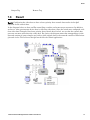
QoS Ensures Real-Time Delivery of Important Messages . . . . . . . . . . . . . . . . . . . . . . . . . . . . . . 71
Hypothetical Scenario. . . . . . . . . . . . . . . . . . . . . . . . . . . . . . . . . . . . . . . . . . . . . . . . . . . . . . . . . . 71
Configuring the Switch for Traffic Prioritization. . . . . . . . . . . . . . . . . . . . . . . . . . 72
Result . . . . . . . . . . . . . . . . . . . . . . . . . . . . . . . . . . . . . . . . . . . . . . . . . . . . . . . . . . . . 73
Chapter 8
8.1
8.2
8.3
8.4
8.5
8.6
8.7
8.8
Automatic . . . . . . . . . . . . . . . . . . . . . . . . . . . . . . . . . . . . . . . . . . . . . . . . . . . . . . . . . . . . . . . . . . . 68
Ingress Limiting . . . . . . . . . . . . . . . . . . . . . . . . . . . . . . . . . . . . . . . . . . . . . . . . . . . . . . . . . . . . . . 69
Egress Limiting . . . . . . . . . . . . . . . . . . . . . . . . . . . . . . . . . . . . . . . . . . . . . . . . . . . . . . . . . . . . . . . 70
QoS Example . . . . . . . . . . . . . . . . . . . . . . . . . . . . . . . . . . . . . . . . . . . . . . . . . . . . . . 71
7.6.1
7.6.2
7.7
7.8
Priority Queuing (QoS, CoS, ToS/DS) . . . . . . . . . . . . . . . . . . . 65
The Benefits of Enabling IGMP . . . . . . . . . . . . . . . . . . . . . . . . . . . . . . . . . . . . . . . . . . . . . . . . . . 78
Virtual Local Area Networks (VLANs) . . . . . . . . . . . . . . . . . . . 80
Introduction to VLANs . . . . . . . . . . . . . . . . . . . . . . . . . . . . . . . . . . . . . . . . . . . . . . 80
Sixnet, LLC
9.2
VLAN Settings . . . . . . . . . . . . . . . . . . . . . . . . . . . . . . . . . . . . . . . . . . . . . . . . . . . . . 81
9.2.1
9.2.2
9.2.3
9.2.4
9.3
9.4
Choosing VLAN Mode of Operation. . . . . . . . . . . . . . . . . . . . . . . . . . . . . . . . . . . . . . . . . . . . . . .
Core Type. . . . . . . . . . . . . . . . . . . . . . . . . . . . . . . . . . . . . . . . . . . . . . . . . . . . . . . . . . . . . . . . . . .
Learning . . . . . . . . . . . . . . . . . . . . . . . . . . . . . . . . . . . . . . . . . . . . . . . . . . . . . . . . . . . . . . . . . . . .
Adding, Editing, or Deleting a VLAN . . . . . . . . . . . . . . . . . . . . . . . . . . . . . . . . . . . . . . . . . . . . . .
81
81
81
81
VLAN Port Settings . . . . . . . . . . . . . . . . . . . . . . . . . . . . . . . . . . . . . . . . . . . . . . . . . 83
VLAN with RSTP. . . . . . . . . . . . . . . . . . . . . . . . . . . . . . . . . . . . . . . . . . . . . . . . . . . . 84
Chapter 10 Modem Access Settings (-5MS-MDM Only) . . . . . . . . . . . . . . . 86
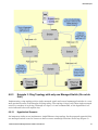
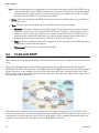
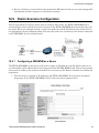
10.1 Introduction to Remote Access . . . . . . . . . . . . . . . . . . . . . . . . . . . . . . . . . . . . . . . 86
10.1.1 Dial-In. . . . . . . . . . . . . . . . . . . . . . . . . . . . . . . . . . . . . . . . . . . . . . . . . . . . . . . . . . . . . . . . . . . . . . 86
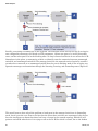
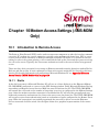
10.1.2 Dial-Out . . . . . . . . . . . . . . . . . . . . . . . . . . . . . . . . . . . . . . . . . . . . . . . . . . . . . . . . . . . . . . . . . . . . 87
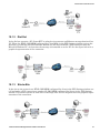
10.1.3 Site-to-Site . . . . . . . . . . . . . . . . . . . . . . . . . . . . . . . . . . . . . . . . . . . . . . . . . . . . . . . . . . . . . . . . . . 87
10.2
10.3
10.4
10.5
10.6
10.7
10.8
10.9
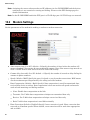
Modem Settings . . . . . . . . . . . . . . . . . . . . . . . . . . . . . . . . . . . . . . . . . . . . . . . . . . . . 88
PPP Mode . . . . . . . . . . . . . . . . . . . . . . . . . . . . . . . . . . . . . . . . . . . . . . . . . . . . . . . . . 89
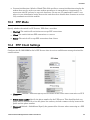
PPP Client Settings . . . . . . . . . . . . . . . . . . . . . . . . . . . . . . . . . . . . . . . . . . . . . . . . . 89
PPP Server Settings. . . . . . . . . . . . . . . . . . . . . . . . . . . . . . . . . . . . . . . . . . . . . . . . .90
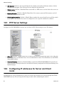
Configuring IP addresses for Server and Client mode. . . . . . . . . . . . . . . . . . . . .90
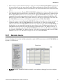
Remote Users . . . . . . . . . . . . . . . . . . . . . . . . . . . . . . . . . . . . . . . . . . . . . . . . . . . . . . 91
Routing . . . . . . . . . . . . . . . . . . . . . . . . . . . . . . . . . . . . . . . . . . . . . . . . . . . . . . . . . . .92
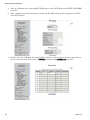
Dial-In Scenario Configuration . . . . . . . . . . . . . . . . . . . . . . . . . . . . . . . . . . . . . . . . 93
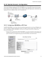
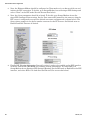
10.9.1 Configuring a 5MS-MDM as a Server . . . . . . . . . . . . . . . . . . . . . . . . . . . . . . . . . . . . . . . . . . . . . 93
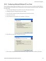
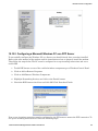
10.9.2 Configuring a Microsoft Windows PC as a Client. . . . . . . . . . . . . . . . . . . . . . . . . . . . . . . . . . . . . 95
10.10 Dial-Out Scenario Configuration . . . . . . . . . . . . . . . . . . . . . . . . . . . . . . . . . . . . . .97
10.10.1 Configuring a 5MS-MDM as a PPP Client . . . . . . . . . . . . . . . . . . . . . . . . . . . . . . . . . . . . . . . . . . 97
10.10.2 Configuring a Microsoft Windows PC as a PPP Server . . . . . . . . . . . . . . . . . . . . . . . . . . . . . . . . 99
10.11 Site-to-Site Scenario Configuration . . . . . . . . . . . . . . . . . . . . . . . . . . . . . . . . . . . 102
10.12 Introduction to Dial-Out Messaging . . . . . . . . . . . . . . . . . . . . . . . . . . . . . . . . . . . 103
10.12.1 Dial-Out Messaging Settings . . . . . . . . . . . . . . . . . . . . . . . . . . . . . . . . . . . . . . . . . . . . . . . . . . .
10.12.2 The Ethernet Modem Sends an ASCII Message . . . . . . . . . . . . . . . . . . . . . . . . . . . . . . . . . . . .
10.12.3 Configuring HyperTerminal. . . . . . . . . . . . . . . . . . . . . . . . . . . . . . . . . . . . . . . . . . . . . . . . . . . . .
10.12.4 Trigger the Ethernet Modem . . . . . . . . . . . . . . . . . . . . . . . . . . . . . . . . . . . . . . . . . . . . . . . . . . .
103
105
106
106
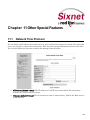
Chapter 11 Other Special Features . . . . . . . . . . . . . . . . . . . . . . . . . . . . . . 108
11.1 Network Time Protocol . . . . . . . . . . . . . . . . . . . . . . . . . . . . . . . . . . . . . . . . . . . . . 108
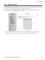
11.2 Set IP Per Port . . . . . . . . . . . . . . . . . . . . . . . . . . . . . . . . . . . . . . . . . . . . . . . . . . . . 109
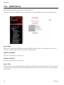
11.3 DHCP Server. . . . . . . . . . . . . . . . . . . . . . . . . . . . . . . . . . . . . . . . . . . . . . . . . . . . . . 110
Chapter 12 Security Settings . . . . . . . . . . . . . . . . . . . . . . . . . . . . . . . . . . . 111
12.1
12.2
12.3
12.4
12.5
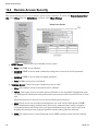
Security Overview . . . . . . . . . . . . . . . . . . . . . . . . . . . . . . . . . . . . . . . . . . . . . . . . . 111
Remote Access Security . . . . . . . . . . . . . . . . . . . . . . . . . . . . . . . . . . . . . . . . . . . . 112
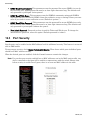
Port Security. . . . . . . . . . . . . . . . . . . . . . . . . . . . . . . . . . . . . . . . . . . . . . . . . . . . . . 114
Port Security MAC Entries . . . . . . . . . . . . . . . . . . . . . . . . . . . . . . . . . . . . . . . . . . 115
IPSEC Settings . . . . . . . . . . . . . . . . . . . . . . . . . . . . . . . . . . . . . . . . . . . . . . . . . . . . 115
Industrial Ethernet Managed Switch Software User Manual
5
12.5.1 Security Policy Database . . . . . . . . . . . . . . . . . . . . . . . . . . . . . . . . . . . . . . . . . . . . . . . . . . . . . . 116
12.5.2 Security Association Database . . . . . . . . . . . . . . . . . . . . . . . . . . . . . . . . . . . . . . . . . . . . . . . . . . 116
12.6 IKE Policy Settings . . . . . . . . . . . . . . . . . . . . . . . . . . . . . . . . . . . . . . . . . . . . . . . . 117
12.6.1 IKE Phase 1 Policies . . . . . . . . . . . . . . . . . . . . . . . . . . . . . . . . . . . . . . . . . . . . . . . . . . . . . . . . . 117
12.6.2 IKE Phase 2 Policies . . . . . . . . . . . . . . . . . . . . . . . . . . . . . . . . . . . . . . . . . . . . . . . . . . . . . . . . . 118
12.6.3 IKE Phase 2 Algorithms . . . . . . . . . . . . . . . . . . . . . . . . . . . . . . . . . . . . . . . . . . . . . . . . . . . . . . . 118
12.7 IKE Preshared Keys and Certificates . . . . . . . . . . . . . . . . . . . . . . . . . . . . . . . . . 119
12.7.1 IKE Preshared Keys . . . . . . . . . . . . . . . . . . . . . . . . . . . . . . . . . . . . . . . . . . . . . . . . . . . . . . . . . . 119
12.7.2 IKE Certificates . . . . . . . . . . . . . . . . . . . . . . . . . . . . . . . . . . . . . . . . . . . . . . . . . . . . . . . . . . . . . . 119
12.8 CLI Commands for IPSEC. . . . . . . . . . . . . . . . . . . . . . . . . . . . . . . . . . . . . . . . . . . 121
12.8.1 SPD/SAD Commands . . . . . . . . . . . . . . . . . . . . . . . . . . . . . . . . . . . . . . . . . . . . . . . . . . . . . . . . 121
12.8.2 IKE Commands . . . . . . . . . . . . . . . . . . . . . . . . . . . . . . . . . . . . . . . . . . . . . . . . . . . . . . . . . . . . . 122
Chapter 13 Using the Command-Line Interface. . . . . . . . . . . . . . . . . . . . 125
13.1 Introduction to Command-Line Interface (CLI). . . . . . . . . . . . . . . . . . . . . . . . . . 125
13.1.1 Accessing the CLI. . . . . . . . . . . . . . . . . . . . . . . . . . . . . . . . . . . . . . . . . . . . . . . . . . . . . . . . . . . . 126
13.2 CLI Commands . . . . . . . . . . . . . . . . . . . . . . . . . . . . . . . . . . . . . . . . . . . . . . . . . . . 126
13.2.1 Global Commands . . . . . . . . . . . . . . . . . . . . . . . . . . . . . . . . . . . . . . . . . . . . . . . . . . . . . . . . . . .
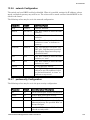
13.2.2 access Configuration . . . . . . . . . . . . . . . . . . . . . . . . . . . . . . . . . . . . . . . . . . . . . . . . . . . . . . . . .
13.2.3 alarm Configuration . . . . . . . . . . . . . . . . . . . . . . . . . . . . . . . . . . . . . . . . . . . . . . . . . . . . . . . . . .
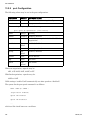
13.2.4 modbus Configuration . . . . . . . . . . . . . . . . . . . . . . . . . . . . . . . . . . . . . . . . . . . . . . . . . . . . . . . .
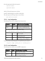
13.2.5 info Configuration . . . . . . . . . . . . . . . . . . . . . . . . . . . . . . . . . . . . . . . . . . . . . . . . . . . . . . . . . . . .
13.2.6 network Configuration. . . . . . . . . . . . . . . . . . . . . . . . . . . . . . . . . . . . . . . . . . . . . . . . . . . . . . . . .
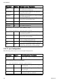
13.2.7 portsecurity Configuration. . . . . . . . . . . . . . . . . . . . . . . . . . . . . . . . . . . . . . . . . . . . . . . . . . . . . .
13.2.8 port Configuration . . . . . . . . . . . . . . . . . . . . . . . . . . . . . . . . . . . . . . . . . . . . . . . . . . . . . . . . . . . .
13.2.9 ring Configuration . . . . . . . . . . . . . . . . . . . . . . . . . . . . . . . . . . . . . . . . . . . . . . . . . . . . . . . . . . . .
13.2.10 rstp Configuration . . . . . . . . . . . . . . . . . . . . . . . . . . . . . . . . . . . . . . . . . . . . . . . . . . . . . . . . . . . .
13.2.11 qos Configuration . . . . . . . . . . . . . . . . . . . . . . . . . . . . . . . . . . . . . . . . . . . . . . . . . . . . . . . . . . . .
13.2.12 vlan Configuration. . . . . . . . . . . . . . . . . . . . . . . . . . . . . . . . . . . . . . . . . . . . . . . . . . . . . . . . . . . .
13.2.13 igmp Configuration . . . . . . . . . . . . . . . . . . . . . . . . . . . . . . . . . . . . . . . . . . . . . . . . . . . . . . . . . . .
13.2.14 chkpt Configuration. . . . . . . . . . . . . . . . . . . . . . . . . . . . . . . . . . . . . . . . . . . . . . . . . . . . . . . . . . .
13.2.15 firmware Configuration . . . . . . . . . . . . . . . . . . . . . . . . . . . . . . . . . . . . . . . . . . . . . . . . . . . . . . . .
13.2.16 tftp Configuration . . . . . . . . . . . . . . . . . . . . . . . . . . . . . . . . . . . . . . . . . . . . . . . . . . . . . . . . . . . .
13.2.17 tz Configuration . . . . . . . . . . . . . . . . . . . . . . . . . . . . . . . . . . . . . . . . . . . . . . . . . . . . . . . . . . . . .
13.2.18 msti Configuration. . . . . . . . . . . . . . . . . . . . . . . . . . . . . . . . . . . . . . . . . . . . . . . . . . . . . . . . . . . .
13.2.19 General Configuration . . . . . . . . . . . . . . . . . . . . . . . . . . . . . . . . . . . . . . . . . . . . . . . . . . . . . . . .
126
127
127
128
128
129
129
130
131
131
132
133
134
135
135
135
136
136
136
Appendix A Licensing and Policies . . . . . . . . . . . . . . . . . . . . . . . . . . . . . . 140
Appendix B Regulatory Statements . . . . . . . . . . . . . . . . . . . . . . . . . . . . . . 143
Appendix C Default Software Configuration Settings . . . . . . . . . . . . . . . 144
C.1
About Default Settings . . . . . . . . . . . . . . . . . . . . . . . . . . . . . . . . . . . . . . . . . . . . . 144
C.1.1
C.1.2
C.1.3
C.1.4
C.1.5
6
Management Port . . . . . . . . . . . . . . . . . . . . . . . . . . . . . . . . . . . . . . . . . . . . . . . . . . . . . . . . . . . .
Port Configuration for Ports 1-9(and above). . . . . . . . . . . . . . . . . . . . . . . . . . . . . . . . . . . . . . . .
Port Mirroring . . . . . . . . . . . . . . . . . . . . . . . . . . . . . . . . . . . . . . . . . . . . . . . . . . . . . . . . . . . . . . .
RSTP/STP Configuration . . . . . . . . . . . . . . . . . . . . . . . . . . . . . . . . . . . . . . . . . . . . . . . . . . . . . .
RSTP/STP Port Configuration . . . . . . . . . . . . . . . . . . . . . . . . . . . . . . . . . . . . . . . . . . . . . . . . . .
144
144
145
145
145
Sixnet, LLC
C.1.6
C.1.7
C.1.8
C.1.9
C.1.10
C.1.11
C.1.12
C.1.13
C.1.14
C.1.15
C.1.16
C.1.17
C.1.18
C.1.19
SNMP Notifications . . . . . . . . . . . . . . . . . . . . . . . . . . . . . . . . . . . . . . . . . . . . . . . . . . . . . . . . . .
IGMP Settings . . . . . . . . . . . . . . . . . . . . . . . . . . . . . . . . . . . . . . . . . . . . . . . . . . . . . . . . . . . . . .
Trap Managers . . . . . . . . . . . . . . . . . . . . . . . . . . . . . . . . . . . . . . . . . . . . . . . . . . . . . . . . . . . . . .
Priority Queuing . . . . . . . . . . . . . . . . . . . . . . . . . . . . . . . . . . . . . . . . . . . . . . . . . . . . . . . . . . . . .
SNMP System Information. . . . . . . . . . . . . . . . . . . . . . . . . . . . . . . . . . . . . . . . . . . . . . . . . . . . .
Remote Access Security . . . . . . . . . . . . . . . . . . . . . . . . . . . . . . . . . . . . . . . . . . . . . . . . . . . . . .
IEEE Tagging . . . . . . . . . . . . . . . . . . . . . . . . . . . . . . . . . . . . . . . . . . . . . . . . . . . . . . . . . . . . . . .
VLAN Mode . . . . . . . . . . . . . . . . . . . . . . . . . . . . . . . . . . . . . . . . . . . . . . . . . . . . . . . . . . . . . . . .
VLAN Port Settings . . . . . . . . . . . . . . . . . . . . . . . . . . . . . . . . . . . . . . . . . . . . . . . . . . . . . . . . . .
Modem Settings . . . . . . . . . . . . . . . . . . . . . . . . . . . . . . . . . . . . . . . . . . . . . . . . . . . . . . . . . . . . .
PPP Settings . . . . . . . . . . . . . . . . . . . . . . . . . . . . . . . . . . . . . . . . . . . . . . . . . . . . . . . . . . . . . . .
Remote Users . . . . . . . . . . . . . . . . . . . . . . . . . . . . . . . . . . . . . . . . . . . . . . . . . . . . . . . . . . . . . .
Routing. . . . . . . . . . . . . . . . . . . . . . . . . . . . . . . . . . . . . . . . . . . . . . . . . . . . . . . . . . . . . . . . . . . .
Dial-Out Messaging . . . . . . . . . . . . . . . . . . . . . . . . . . . . . . . . . . . . . . . . . . . . . . . . . . . . . . . . . .
145
145
146
146
146
146
147
147
147
147
148
148
148
148
Appendix D SNMP Support . . . . . . . . . . . . . . . . . . . . . . . . . . . . . . . . . . . . . 150
Appendix E Concepts and Definitions . . . . . . . . . . . . . . . . . . . . . . . . . . . . 152
Appendix F AT Command Summary (-MDM Models Only . . . . . . . . . . . . 156
F.1
F.2
AT Commands . . . . . . . . . . . . . . . . . . . . . . . . . . . . . . . . . . . . . . . . . . . . . . . . . . . . 156
S-Registers . . . . . . . . . . . . . . . . . . . . . . . . . . . . . . . . . . . . . . . . . . . . . . . . . . . . . . .157
Appendix G Service Information . . . . . . . . . . . . . . . . . . . . . . . . . . . . . . . . . 159
G.1
Product Support. . . . . . . . . . . . . . . . . . . . . . . . . . . . . . . . . . . . . . . . . . . . . . . . . . . 160
Appendix H License Agreements . . . . . . . . . . . . . . . . . . . . . . . . . . . . . . . . 161
H.1
H.2
H.3
H.4
H.5
H.6
H.7
H.8
H.9
H.10
H.11
H.12
H.13
H.14
H.15
PCRE Library . . . . . . . . . . . . . . . . . . . . . . . . . . . . . . . . . . . . . . . . . . . . . . . . . . . . . 161
libpcap Software. . . . . . . . . . . . . . . . . . . . . . . . . . . . . . . . . . . . . . . . . . . . . . . . . . . 162
lighttpd Software . . . . . . . . . . . . . . . . . . . . . . . . . . . . . . . . . . . . . . . . . . . . . . . . . . 163
spawn-fcgi Software . . . . . . . . . . . . . . . . . . . . . . . . . . . . . . . . . . . . . . . . . . . . . . . 163
ipsec-tools Software . . . . . . . . . . . . . . . . . . . . . . . . . . . . . . . . . . . . . . . . . . . . . . . 164
net-snmp Software . . . . . . . . . . . . . . . . . . . . . . . . . . . . . . . . . . . . . . . . . . . . . . . . . 165
FastCGI Library . . . . . . . . . . . . . . . . . . . . . . . . . . . . . . . . . . . . . . . . . . . . . . . . . . .170
watchdog Software . . . . . . . . . . . . . . . . . . . . . . . . . . . . . . . . . . . . . . . . . . . . . . . . 170
GPLv2 (General Public License v2) . . . . . . . . . . . . . . . . . . . . . . . . . . . . . . . . . . . 171
Crossbrowser/x-tools Library . . . . . . . . . . . . . . . . . . . . . . . . . . . . . . . . . . . . . . . . 176
OpenSSL License. . . . . . . . . . . . . . . . . . . . . . . . . . . . . . . . . . . . . . . . . . . . . . . . . . 188
Open SSH License . . . . . . . . . . . . . . . . . . . . . . . . . . . . . . . . . . . . . . . . . . . . . . . . . 190
PPP License . . . . . . . . . . . . . . . . . . . . . . . . . . . . . . . . . . . . . . . . . . . . . . . . . . . . . . 191
Shadow License . . . . . . . . . . . . . . . . . . . . . . . . . . . . . . . . . . . . . . . . . . . . . . . . . . . 196
Sudo License . . . . . . . . . . . . . . . . . . . . . . . . . . . . . . . . . . . . . . . . . . . . . . . . . . . . . 198
Industrial Ethernet Managed Switch Software User Manual
7
Product Information
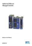
Products Covered in This Manual
This manual applies to firmware v5.0 in the following products:
•
SLX-5MS-# Slim Line Managed Ethernet switch with 5 10/100 ports
•
SLX-5MS-MDM-# Managed Ethernet switch with 5 10/100 ports and integrated modem
•
SLX-8MS-# Slim Line Managed Ethernet switch with 8 10/100 ports
•
SLX-8MG Slim Line Managed Ethernet switch with 8 10/100/1000 ports
•
SLX-10MG Managed Ethernet switch with 7 10/100 and 3 Gigabit ports
•
SLX-16MS Managed Ethernet switch with 16 10/100 ports
•
SLX-18MG Managed Ethernet switch with 16 10/100 and 2 Gigabit ports
•
EK26 Rack Mount Gigabit Managed Ethernet switch with 26 ports
•
EF26 Rack Mount Managed Ethernet switch with 26 10/100 ports
•
EK32 Rack Mount Gigabit Managed Ethernet switch with 32 ports
•
EF32 Rack Mount Managed Ethernet switch with 32 10/100 ports
•
ET-5MS-OEM -# - 5 port OEM managed switch
•
ET-8MS-OEM -# - 8 port PC104 OEM managed switch
Firmware Downloads
Download the latest firmware from the web site:
http://www.sixnet.com
Read the firmware release history on the web site:
http://www.sixnet.com
8
Software User Manual Download
Get the latest version of this user manual:
http://www.sixnet.com
Industrial Ethernet Managed Switch Software User Manual
9
Chapter 1 Accessing the Setup Interfaces
1.1
Quick Start Guide to Web User Interface
Use this guide to quickly configure the switch over an Ethernet connection.
Note: This is the recommended method for initially accessing the switch.
1. The default IP address and subnet mask of the switch is 192.168.0.1 and 255.255.255.0. This
means your PC must be temporarily set to a compatible IP address (example: 192.168.0.100).
Follow these directions to do so:
1. Unplug your computer from your Local Area Network (LAN).
2. Go to the Control Panel on your computer.
3. Go to Network Connections.
4. Access the Properties window for your LAN.
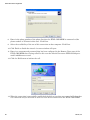
5. Access the Properties for your Internet Protocol (TCP/IP).
6. Select “Use the following IP address” and enter an IP of 192.168.0.100 and a subnet of
255.255.255.0.
10
Quick Start Guide to Web User Interface
7. Select OK to activate the change. Reboot your PC if prompted.
2. Connect an Ethernet patch cable between your PC and any of the RJ45 Ethernet ports on the
switch.
3. To access the switch use a web browser program such as Internet Explorer, Mozilla Firefox, or
other.
4. Type the switches default IP address 192.168.0.1 in the web browser's address bar and hit enter
on your keyboard.
5. A log in window will open prompting you for a login name and password. Enter 'admin' for the
login and 'admin' for the password.
6. Read the Software License Agreement and Click the “I accept the License” button.
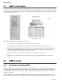
7. Navigate through the configuration screens using the tree on the left hand side.
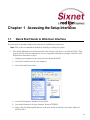
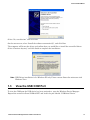
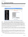
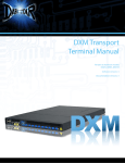
8. Selecting Quick Setup brings up the System Settings menu. This menu is used to configure the
IP address (DHCP or static), subnet mask, redundancy protocol, system name, contact, and location information. See the image below.
Industrial Ethernet Managed Switch Software User Manual
11
USB Driver Installation
9.
Set the desired IP address and subnet that are compatible with the network for which this
switch will reside, or you can enable DHCP. Select Commit to activate your new settings.
10. Restore your PC back to its normal network settings (IP and subnet) and reconnect it to your
LAN.
11. Connect the switch to your LAN or the network it will reside and now you can use the IP
address you just assigned to access your switch. If you enabled DHCP then you will need to contact your LAN administrator to determine the IP address that was assigned.
12. Once you regain access to your switch then you can do the following:
a. The default administrative password can be changed from the Remote Access Security menu.
b. The individual ports on the switch are configured to a set of defaults and auto-selects that
should get you started quickly with no necessary configuration. Customizing the port settings
by enabling/disabling a port, choosing the speed, duplex, or flow control is accessed from the
Port Configuration menu.
c.
The Rapid Spanning Tree Protocol (RSTP) is disabled by default in the switch. The RSTP settings can be changed from the from Redundancy Settings screens.
d. Check the operational status of the switch by accessing the Monitoring menu.
e. The modem and PPP settings are found in the Remote Access Settings menu.
Note: The switch can also be initially configured using the serial port. However, the Ethernet
method described above is recommended. Refer to Appendix J if you wish to use the
serial port method.
1.2
USB Driver Installation
Sixnet managed switches are equipped with both a USB port and an RS232 port for terminal access. In
order to take advantage of the USB port, please visit www.sixnet.com or browse your Sixnet CD to
install the USB driver.
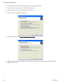
After completing the installation, you may then connect the switch via USB. The New Hardware Wizard will appear:
12
Sixnet, LLC
View the USB COM Port
Select “No, not this time” and click Next.
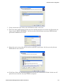
On the next screen, select “Install the software automatically”, and click Next.
The computer will locate the driver and confirm that you would like to install the unverified driver.
Select “Continue Anyway” and click finish to complete the installation.
Note: USB Driver installation is for Windows XP only. Please contact Sixnet for assistance with
Windows Vista.
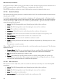
1.3
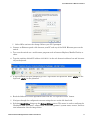
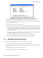
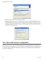
View the USB COM Port
To view the COM port the USB device has been assigned to, open the Windows Device Manager.
Expand the section for Ports (COM & LPT) and locate the port labeled “USB Serial Device”.
Industrial Ethernet Managed Switch Software User Manual
13
Quick Start Guide to Terminal User Interface
The COM number following the name can now be used to access the switch using the terminal interface.
The USB and RS232 ports cannot be connected simultaneously. Please connect only the cable type you
wish to use to communicate with the switch.
1.4
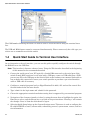
Quick Start Guide to Terminal User Interface
As an alternative to the web interface, you can use this guide to quickly configure the switch through
the RS232 Port or the USB Port.
Note: This interface is for more advanced users. Using the Web interface described in the beginning
of this manual is the recommended method.
1. Connect the serial port of your PC (typically a female DB9 connector) to the serial port of the
switch (female RJ45 connector) or on units with a USB port, connect a USB cable from a USB
port on your PC to the USB port on the Switch. Refer to the hardware user manual for details on
how to make this connection. Contact your switch provider to purchase a pre-wired interface
cable or USB cable if necessary.
2. Configure a terminal program (such as HyperTerminal) for 9600, 8N1 and no flow control. See
Section further below for more details.
3. Type 'admin' for the login name and 'admin' for the password.
4. Choose the appropriate terminal emulation setting that is supported by your terminal program.
5. Navigation of the character interface is done by using the arrow keys to highlight the option, the
Enter key to select, and the Escape key to go back to the previous menu. Pressing ‘c’ will commit
the changes. Press ‘x’ from the main menu to logout.
6. Selecting Quick Setup brings up the System Settings menu. This menu is used to configure the
IP address (DHCP or static), subnet mask, redundancy protocol, system name, contact, and location information.
14
Sixnet, LLC
Using Microsoft HyperTerminal
7. Set the desired IP address and subnet that are compatible with the network for which this
switch will reside, or you can enable DHCP. Select “c” to activate your new settings.
8. Now you can access the switch via the web interface or you can continue to make configuration
changes using this text interface.
9. Using the text interface you can do the following:
1. The default administrative password can be changed from the Remote Access Security menu.
2. The individual ports on the switch are configured to a set of defaults and auto-selects that
should get you started quickly with no necessary configuration. Customizing the port settings
by enabling/disabling a port, choosing the speed, duplex, or flow control is accessed from the
Port Configuration menu.
3. The Rapid Spanning Tree Protocol (RSTP) is disabled by default in the switch. The RSTP set-
tings can be changed from the from Redundancy Settings screens.
4. Check the operational status of the switch by accessing the Monitoring menu.
5. The modem and PPP settings are found in the Remote Access Settings menu.
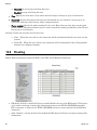
1.5
Using Microsoft HyperTerminal
Configure Microsoft Windows HyperTerminal for use with the switch as follows:
1. Create a new connection by choosing New Connection from the File menu.
2. In the Connection Description dialog, give the connection a name such as “Managed Switch” and
click OK.
3. In the Connect To dialog, choose the correct COM port.
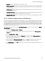
4. In the COM Properties dialog, choose the following settings:
Industrial Ethernet Managed Switch Software User Manual
15
Using Microsoft HyperTerminal
•
9600 bits per second (Bps or Baud)
•
8 data bits, no parity, 1 stop bit
•
no flow control.
5. Click OK.
6. Open the Connection Properties dialog by choosing Properties from the File menu.
7. Click on Settings to raise the setting tab.
8. Select VT100 from the Emulation list.
9. Click Terminal Setup.
10. In Terminal Settings, check Cursor keypad mode & hit OK.
11. Click OK to close the Connection Properties dialog.
Once the terminal screen comes up the switch prompts for a login name. It may be necessary to press
Enter once or twice to see the login prompt. The default login user and password are both 'admin'. After
the login and password prompts, select VT100 by pressing 4 and then Enter The main administrative
menu will now appear and the managed switch is now ready for full configuration.
16
Sixnet, LLC
Chapter 2 Initial Setup and Configuration
2.1
Overview
The Industrial Ethernet Managed Switch is a configurable device that facilitates the interconnection of
Ethernet devices on an Ethernet network. This includes computers, operator interfaces, I/O, controllers, RTUs, PLCs, other switches/hubs or any device that supports the standard IEEE 802.3 protocol.
This switch has all the capabilities of a store and forward Ethernet switch plus advanced management
features such as SNMP, RSTP and port mirroring. This manual details how to configure the various
management parameters in this easy to use switch.
2.2
Introduction
To take full advantage of all the features and resources available from the switch, it must be configured
for your network.
The switch implements Rapid Spanning Tree Protocol (RSTP) and Simple Network Management Protocol (SNMP) to provide most of the services offered by the switch. Rapid Spanning Tree Protocol allows
managed switches to communicate with each other to ensure that there exists only one active route
between each pair of network nodes and provides automatic failover to the next available redundant
route. A brief explanation of how RSTP works is given in the Spanning Tree section.
The switch is capable of communicating with other SNMP capable devices on the network to exchange
management information. This statistical/derived information from the network is saved in the Management Information Base (MIB) of the switch. The MIB is divided into several different information
storage groups. These groups will be elaborated in detail in the Management and SNMP information
section of this document.
The switch implements Internet Group Management Protocol (IGMP) to optimize the flow of multicast
traffic on your network.
The switch supports both port-based and tag-based Virtual LANs for flexible integration with VLANaware networks with support for VLAN-unaware devices.
Additional technical documentation is available in the appendices of this manual. These appendices
provide important terminology/definitions, an administrative menu map, example of an RSTP network
topology, and factory default information extracted from the switch.
17
Administrative Interface Access
2.3
Administrative Interface Access
There are several administrative interfaces to the switch:
1. A graphical web interface accessible via the switch's built-in web server. Both http and secure
https with SSL are supported. (Note: This is the recommended method for managing the
switch.)
2. A terminal interface via the RS232/USB port or over the network using telnet or Secure Shell
(SSH).
3. An SNMP interface can be used to read/write many settings.
4. CLI (Command Line Interface) can be used to read/write most settings. See the separate CLI
User Manual for details.
Initial setup must be done using an Ethernet connection (recommended) or the serial port. See Section
1 for quick start guides.
2.3.1
Using the Graphical (Web) Interface
The graphical interface is provided via a web server in the switch and can be accessed via a web
browser such as Opera, Mozilla, or Internet Explorer.
Note: JavaScript must be supported and enabled in your browser for the graphical interface to
work correctly.
HTTP and HTTPS (secure HTTP) are supported for access to the web server. By default, both protocols
are enabled. Either or both may be disabled to secure the switch. (See the Remote Access Security topic
in this section.)
To access the graphical interface, enter a URL like HTTP://192.168.0.1 in your browser's address bar.
Replace “http” with “https” to use secure http and replace “192.168.0.1” with your switch's IP address if
you've changed it from the factory default.
The web server in the switch uses a signed security certificate. When you access the server via https,
you may see a warning dialog indicating that the certificate was signed by an unknown authority. This
is expected and to avoid this message in the future you can choose to install the certificate on your computer.
Note: This manual describes and depicts the web user interface in detail. The terminal interface is
not specifically shown but is basically the same.
2.4
Configuring the Switch for Network Access
To control and monitor the switch via the network, it must be configured with basic network settings,
including an IP address and subnet mask. Refer to the quick start guide in Section 1 for how to initially
access your switch.
To configure the switch for network access, select Quick Setup from the Main Menu to reach the System Settings menu. The settings in this menu control the switch's general network configuration.
18
Sixnet, LLC
Configuring the Ethernet Ports
•
DHCP Enabled/Disabled: The switch can automatically obtain an IP address from a server
using the Dynamic Host Configuration Protocol (DHCP). This can speed up initial set up, as the
network administrator does not have to find an open IP address.
•
IP Address and Subnet Mask Configuration: The IP address for the switch can be changed to a
user-defined address along with a customized subnet mask to separate subnets.
Note: Advanced users can set the IP address to 0.0.0.0 to disable the use of an IP address for additional security. However, any features requiring an IP address (i.e., web interface, etc.) will
no longer be available.
•
Default Gateway Selection: A Gateway Address is chosen to be the address of a router that connects two different networks. This can be an IP address or a Fully Qualified Domain Name
(FQDN) such as “domainname.org”.
•
NTP Server: The IP address or domain name of an NTP (Network Time Protocol) server from
which the switch may retrieve the current time at startup. Please note that using a domain
name requires that at least one domain name server be configured. See Chapter 11 Other Special Features on page 108 for more details.
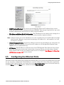
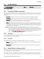
2.5
Configuring the Ethernet Ports
The switch comes with default port settings that should allow you to connect to the Ethernet Ports with
out any necessary configuration. Should there be a need to change the name of the ports, negotiation
settings or flow control settings, you can do this in the Port Configuration menu. Access this menu by
selecting Setup from the Main menu, and then selecting Main Settings.
Industrial Ethernet Managed Switch Software User Manual
19
Configuring the Ethernet Ports
•
Port Name: Each port in the managed switch can be identified with a custom name. Specify a
name for each port here.
•
Admin: Ports can be enabled or disabled in the managed switch. For ports that are disabled,
they are virtually non-existent (not visible in terms of switch operation or spanning tree algorithm). Choose to enable or disable a port by selecting Enabled or Disabled, respectively.
•
Negotiation: All copper ports and gigabit fiber ports in the managed switch are capable of autonegotiation such that the fastest bandwidth is selected. Choose to enable auto-negotiation or use
fixed settings. 100Mbps Fiber ports are Fixed speed only.
•
Speed/Duplex/Flow Control: The managed switch accepts three local area network Ethernet
Standards. The first standard, 10BASE-T, runs 10Mbps with twisted pair Ethernet cable
between network interfaces. The second local area network standard is 100BASE-T, which runs
at 100Mbps over the same twisted pair Ethernet cable. Lastly, there is 100BASE-F, which
enables fast Ethernet (100Mbps) over fiber.
These options are available:
•
10h–10 Mbps, Half Duplex
•
10f –10 Mbps, Full Duplex
•
100h–100 Mbps, Half Duplex
•
100f –100 Mbps, Full Duplex
•
1000f–1000 Mbps, Full Duplex
On managed switches with gigabit combination ports, those ports with have two rows, a standard row
of check boxes and a row labeled “SFP” with radio buttons. The SFP setting independently sets the
20
Sixnet, LLC
Configuring the Ethernet Ports
speed at which a transceiver will operate if one is plugged in. Otherwise, the switch will use the fixed
Ethernet port and the corresponding settings for it.
Note: When 100F is selected for the SFP of a gigabit combination port, the corresponding fixed
Ethernet jack will be disabled unless it is changed back to 1000F.
Flow control can also be enabled or disabled, and is indicated by 'FC' when enabled. Devices use flow
control to ensure that the receiving devices takes in all the data without error. If the transmitting
device sends at a faster rate than the receiving device, than the receiving device will eventually have
its buffer full. No further information can be taken when the buffer is full, so a flow control signal is
sent to the transmitting device to temporarily stop the flow of incoming data.
Industrial Ethernet Managed Switch Software User Manual
21
Chapter 3 Configuration Management and
Firmware Updates
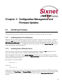
3.1
Installing Firmware
The Install Firmware page allows the inactive firmware to be replaced with a new version.
3.1.1
Installing from the Local System
Firmware may be directly uploaded to the switch from the local system. Use the “Browse...” button to
locate the .fwb firmware file. If an MD5 checksum of the file is available, it may be entered into the
MD5 Checksum (Optional) field. Providing a checksum will ensure the firmware arrives at the switch
intact and without any glitches. An MD5 checksum is not required. Click the Install from file button to
begin the firmware installation process.
3.1.2
Installing from a Remote Server
Firmware may be fetched by the switch from a remote machine serving the .fwb firmware file. The
server must be providing the file via TFTP, HTTP, HTTPS, FTP, or FTPS.
Enter the address of the server in the Server Address field. This may be an IP address, or a domain
name if a DNS server has been configured on the System Settings page. Literal IPv6 addresses must be
surrounded with square brackets.
For example, to use the address:
fdda:2301::2
enter it as:
[fdda:2301::2]
If the server requires a user name and password to retrieve files (not available for TFTP), enter those
credentials in the User Name and Password fields, respectively. If the server does not require this kind
of authentication and will allow anybody to download files, check the Anonymous Download box
instead.
22
Managing Firmware
Enter the full path to the file on the server in the Remote filename field.
If an MD5 checksum is available for the file, it may be provided in the MD5 Checksum (Optional) field.
Providing a checksum will ensure that the file is received intact and without any glitches. An MD5
checksum is not required.
Click on the Update from Server button to begin the firmware installation process.
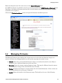
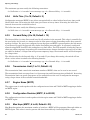
3.2
Managing Firmware
The Manage Firmware page displays the current status of each of the two firmware images on a
switch, and allows for changing which one will run the next time the switch is reset.
•
Default–Shows the current default firmware image to run when the switch is reset. May be
changed to run a different firmware on the next reset.
•
Running–Shows the current running firmware image. This may be different from the current
default firmware image if the switch failed to boot recently.
•
Version–Displays the firmware version number for each installed firmware. If the version cannot be determined, this will report “Unknown”.
•
Health–Shows the health of each firmware image. The health can be one of the following:
Industrial Ethernet Managed Switch Software User Manual
23
Advanced Operations
•
Healthy–The firmware is running or is expected to be in good enough shape to run.
•
Broken–The firmware is known to be in a state that would prevent it from booting. The
Default column will not allow this image to be selected for booting.
•
Unknown–The firmware may be bootable, but the switch cannot be certain. This will happen
if the switch is running the non-default firmware. This can happen if the default firmware
somehow became corrupt, or if the switch lost power part way through booting.
If the firmware that is currently running is not the default, and the switch is reset without explicitly
saving the default, the current firmware will be run again. To boot the firmware marked as the default,
commit this page without making any changes and then reset the switch.
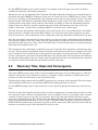
3.3
Advanced Operations
Use the Advanced Operations Menu for saving and restoring configurations, reloading factory defaults,
resetting the switch, updating the firmware, and setting up remote access.
Note: The web interface supports direct transfers to and from the system where your browser is
running. Alternatively, you can use TFTP (Trivial File Transfer Protocol) for file transfers.
Access to the Advanced Operations menu is available by selecting the option in the Main menu.
3.3.1
Saving and Retrieving Files
The Configuration Management and Update Firmware features allow you to Browse to save and
retrieve files directly from your local system. This is the easiest and recommended method. Alternatively, you can use a TFTP (Trivial File Transfer Protocol) server to centralize the storage of your con-
24
Sixnet, LLC
Configuration Management
figuration and firmware files. Free TFTP servers for Windows and Linux are available on the web.
They are generally easy to install and setup.
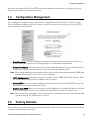
3.4
Configuration Management
One “checkpoint” (backup) version of the switch's configuration can be stored in a local file on the
switch. Unlimited backups can also be saved to your local system (web interface only) or to a TFTP
server elsewhere on the network.
•
Save Checkpoint: Saves a checkpoint configuration in the switch, which may be used later to
revert back to the current state if changes lead to an undesirable configuration.
•
Restore Checkpoint: Reverts to the settings in the saved checkpoint. You can optionally choose
to keep your current network settings or use the ones in the checkpoint file.
Note: The current administrator's password will remain in effect after the restoration. SNMP passwords will be restored to the values in the checkpoint.
•
TFTP Configuration: Specifies the name or IP address of the TFTP (Trivial File Transfer Protocol) server where configuration checkpoints may be stored.
•
Save to TFTP: Saves the current configuration checkpoint file to the defined TFTP server. You
must specify the name of a file on the server.
•
Retrieve from TFTP: Retrieves a previously saved configuration checkpoint file from the defined
TFTP server. After retrieval, the configuration still must be restored to be made active.
Note: The web interface also allows you to download (save) and upload (retrieve) files directly from
your local system. No TFTP server is needed.
3.5
Factory Defaults
This option sets the switch back to factory default settings. The switch will automatically restart (reset)
to put the default settings into effect.
Industrial Ethernet Managed Switch Software User Manual
25
Reset Switch
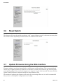
3.6
Reset Switch
This feature will cause the switch to perform a “soft” restart (software reset). A software reset may take
30 seconds or more depending on what features are enabled in the switch.
3.7
Update Firmware Using the Web Interface
Firmware updates are released periodically to add features and fix problems. The recommended and
easiest way to update firmware is from the web interface. It allows you to Browse and select the firmware update package from your local computer or a computer on your local network. Then just click the
Update from File button to load and install the latest firmware files.
This method of updating the firmware will retain all your settings. However, it is still recommended
that you save a “checkpoint” configuration as a backup.
26
Sixnet, LLC
Update Firmware Using a TFTP Server
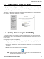
3.8
Update Firmware Using a TFTP Server
Another option for updating firmware is via a TFTP server elsewhere on the network. Simply specify
the IP address of the remote TFTP server and the filename of the update. If necessary, the switch will
automatically reboot after installing the new firmware files. After the reboot you may see an “Internal
Server Error” message. Simply click refresh on your browser to reestablish communications with the
switch.
This method of updating the firmware will retain all your settings. However, it is still recommended
that you save a “checkpoint” configuration as a backup.
3.9
Updating Firmware Using the Switch Utility
In the event the switch is not reachable by the web or CLI interfaces, the unit can be recovered and
reloaded using the switch utility. This operation will erase all configuration settings and set them to
factory defaults.
Steps for using the utility to load firmware:
1. Download and install the Switch Utility program. The Java Runtime is required for the switch
utility to run, and will be loaded as part of the installation process. You may download the
switch utility from www.sixnet.com.
2. Download the latest firmware bundle from www.sixnet.com and save it to the desired location
on your PC.
3. Run the Switch Utility from the shortcut on your desktop.
Note: Please ensure that a TFTP service is not running and no other program is using your
serial port prior to starting the Switch Utility.
Industrial Ethernet Managed Switch Software User Manual
27
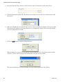
Updating Firmware Using the Switch Utility
4. From the Switch Utility, browse to the location of the 5.0 firmware bundle and select it.
5. Choose the network adapter (by IP address) and serial port you will use to communicate with
the switch.
6. Enter the IP address you would like the switch to have once the new firmware has been loaded.
Note that the IP address of the switch must be on a compatible subnet of the network adapter
you are loading firmware from.
7. Click the Load button to begin loading firmware.
When prompted, cycle power to the switch. As the firmware loads, the progress meter should
increase to 100%, and a message will confirm that the load was successful.
The switch should now be fully accessible at the IP address specified in the Utility.
28
Sixnet, LLC
Chapter 4 Monitoring the Current State of the
Switch
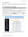
4.1
System Information
The System Information page displays identifying information about the switch, and current network
settings.
•
Model number of the switch.
•
Description is available via SNMP as SYSTEM.SYSDESCR.0. This is the basic description of
the switch.
•
System Name: The hostname of the switch. It must contain only letters, digits, and dashes. This
may be read or written via SNMP as SYSTEM.SYSNAME.0.
•
Switch Location: The physical location of the switch (the cabinet, closet, rack, etc. it is in). This
may be read or written via SNMP as SYSTEM.SYSLOCATION.0.
29
Port Status
•
Contact: Typically, this parameter includes the contact's name and e-mail address. This may be
read or written via SNMP as SYSTEM.SYSCONTACT.0.
•
IP Address: IP address of the switch
•
Subnet Mask: Subnet Mask of the switch. Readable via SNMP as RFC1213-MIB::IPADENTNETMASK.<IPADDRESS> where <IPADDRESS> is the IP address of the switch (e.g., 10.2.0.1).
•
Gateway: Gateway IP configured for the switch. Readable via SNMP as RFC1213MIB::IPROUTENEXTHOP.
•
Serial Number is a unique serial number assigned to the switch at the factory. This number cannot be set in the user interface.
•
Firmware Revision is the version of the firmware currently in the switch.
•
MAC Address: Media Access Control number of the switch (cannot be set).
•
System Up Time is available via SNMP as SYSTEM.SYSUPTIME.0. This is the amount of time
since the switch was last powered up.
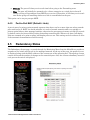
4.2
Port Status
The Port Status page displays the current status of each port. The display will be updated every 5 seconds.
The following information for each port is displayed:
•
Port: The number of the port. This corresponds to the labels on the switch.
•
Name: The user-configured name of the port.
•
Admin: The configured state of the port (enabled or disabled).
•
Link: The current state of the Ethernet link at a port. If there is a proper connection link status
will show Up. If the port is disabled, not connected, or has a faulty connection, the link status
will show Down.
•
Negotiation: Shows whether auto-negotiation is enabled (Auto) or disabled (Fixed).
•
Speed/Duplex: Shows the speed of the connection (10, 100 or 1000 Mbps) and the duplex status
(h = half duplex; f = full duplex).
4.3
Power and OK Status
A separate area below the Port Status grid mimics the P1, P2, and OK status LEDs on the switch.
When P1 is highlighted, power is detected on the first terminal input. P2 is highlighted when power is
detected on the second terminal input.
OK (To PLC in the SL-5MS-MDM) is highlighted when power is detected on the first and second terminal inputs and the switch software is running. The OK output can also be configured as an alarm for a
broken ring or a lost link on designated port(s).
30
Sixnet, LLC
Network Statistics
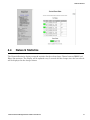
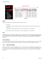
4.4
Network Statistics
The Network Statistics displays network statistics for the selected port. Choose between RMON and
Ether-like statistics. The display will be updated every 5 seconds and the change since the last refresh
will be displayed in the change column.
Industrial Ethernet Managed Switch Software User Manual
31
Real-Time Ring Status
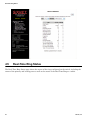
4.5
Real-Time Ring Status
The Real-Time Ring Status page shows the status of the rings configured on the switch, including the
status of the primary and backup ports as well as the status of the Real-Time Ring as a whole.
32
Sixnet, LLC
Configuration Summary
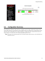
4.6
Configuration Summary
The Configuration Summary Page provides a complete overview of the configuration settings of the
switch. The summary is generated in a print-friendly format. If an NTP server is configured, the report
will also report a timestamp. To save these settings to a configuration file, click the “Save these settings” button to be redirected to the Configuration Management screen.
Note: This page is for viewing settings only. To change settings, please browse to the individual configuration screens.
Industrial Ethernet Managed Switch Software User Manual
33
Modem Status
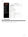
4.7
Modem Status
The Modem Status page shows the status and statistics of the PPP connection along with the connected
state of the modem. The display will be updated every 5 seconds.
34
Sixnet, LLC
MAC Address Table
PPP mode: Indicates whether the 5MS-MDM is in Client or Server mode.
PPP state: Current state of the PPP connection - Up or Down.
Uptime: Time the PPP connection has been up. It will be blank if there is no PPP connection.
IP Address: The IP address being used by the PPP connection.
Subnet mask: The Subnet Mask being used by the PPP connection.
Received: The number of Bytes, Packets and Errors that have come in via the PPP connection.
Transmitted: The number of Bytes, Packets and Errors that have been transmitted by the PPP connection.
Input From PLC (From PLC): Status of the 'From PLC' input on the SLX-5MS-MDM. TRUE is displayed when a voltage is detected on the From PLC input. FALSE is displayed when no voltage is
detected.
Carrier Detect (CD): Displays the status of the modem connection as either Connected or Disconnected.
4.8
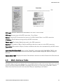
MAC Address Table
The MAC address table page displays the current MAC address table of the switch. This data can be filtered by the Filter Database ID(FID), the port(s) of discovery or by all or part of the MAC address.
Please note that Port 33 or 65 is the internal CPU port, depending on the model.
Industrial Ethernet Managed Switch Software User Manual
35
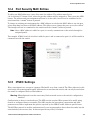
Alarm (OK) Output
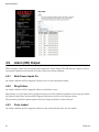
4.9
Alarm (OK) Output
These settings control the events that will trigger the alarm output. The OK discrete output is on during normal conditions and turned off in the event of an alarm condition.
4.9.1
Both Power Inputs On
An alarm condition will be triggered if power is not on for both power inputs.
4.9.2
Ring Failure
An alarm condition will be triggered when a ring failure occurs.
Ring failure on a local port will be triggered when one of this switch's neighbors in the ring goes down;
the general ring failure option will be triggered when any switch in the ring goes down.
The general ring failure option implies that local ring port failure is also detected.
4.9.3
Ports Linked
An alarm condition will be triggered whenever any of the selected ports are not linked.
36
Sixnet, LLC
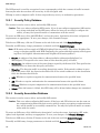
Modbus Monitoring
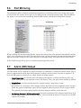
4.10
Modbus Monitoring
These settings control whether and how the switch will respond to Modbus requests. Modbus registers
are available for monitoring link status on each Ethernet port, the power and OK status, and the status
of each configured Real-Time Ring.
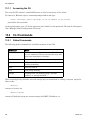
4.10.1
Enabled
If selected, the switch will respond to Modbus requests.
4.10.2
Station Number
The Modbus station number that the switch will respond as.
4.10.3
Transport Layers
The switch will respond to Modbus requests only on the chosen transport layers.
4.10.4
TCP Timeout
If a new TCP connection is received when there are no more free connections (see the TCP Connection
Limit), this determines what happens:
0
The least recently active connection will be dropped in favor of the new connection.
>0
The least recently active connection will be dropped in favor of the new connection, but only if the least recently active connection has been inactive for
at least this many seconds.
None
The new connection will be dropped immediately after it is accepted.
Industrial Ethernet Managed Switch Software User Manual
37
Modbus Monitoring
4.10.5
TCP Connection Limit
The maximum number of active TCP connections that the Modbus server will maintain. Above this
limit, the TCP Timeout value will be used to decide how new connections should be handled.
4.10.6
Port
The TCP/UDP port number on which to listen for new connections/requests.
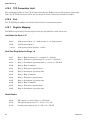
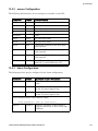
4.10.7
Register Mapping
The Modbus registers (all discrete inputs) that may be polled for switch status are:
Link Status for Ports 1-16
10001
Link status of port 1 (1 = link present, 0 = no link present)
10002
Link status of port 2
...10016
Link status of port (register - 10000)
Real-Time Ring Status for Rings 1-4
10017
Ring 1: Ring is complete (1 = complete, 0 = broken)
10018
Ring 1: First port is passing data (1 = active, 0 = blocked)
10019
Ring 1: Second port is passing data (1 = active, 0 = blocked)
10020
Ring 2: Ring is complete
10021
Ring 2: First port is passing data
10022
Ring 2: Second port is passing data
10023
Ring 3: Ring is complete
10024
Ring 3: First port is passing data
10025
Ring 3: Second port is passing data
10026
Ring 4: Ring is complete
10027
Ring 4: First port is passing data
10028
Ring 4: Second port is passing data
Switch Status
38
10030
OK output (1 = on/no alarm, 0 = off/alarm)
10031
First power input active (1 = P1 on, 0 = P1 off)
10032
Second power input active (1 = P2 on, 0 = P2 off)
Sixnet, LLC
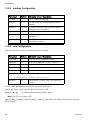
Modbus Monitoring
Extended Link Status for Ports 1-99
10101
Link status of port 1 (1 = link present, 0 = no link present)
10102
Link status of port 2
...10199
Link status of port (register - 10100)
Extended Ring Status for Rings 1-25
10200
Ring 1: Ring is complete (1 = complete, 0 = broken)
10201
Ring 1: First port is passing data (1 = active, 0 = blocked)
10202
Ring 1: Second port is passing data (1 = active, 0 = blocked)
10203
Ring 1: Reserved (always 0)
...10299
Ring X status (X = ?(register - 10200) ÷ 4? + 1)
10200 + (X - 1) × 4 + 0 Ring X: Ring is complete
10200 + (X - 1) × 4 + 1 Ring X: First port is passing data
10200 + (X - 1) × 4 + 2 Ring X: Second port is passing data
10200 + (X - 1) × 4 + 3 Ring X: Reserved (always 0)
Extended Switch Status
10300
OK output (1 = on/no alarm, 0 = off/alarm)
10301
First power input active (1 = P1 on, 0 = P1 off)
10302
Second power input active (1 = P2 on, 0 = P2 off)
Industrial Ethernet Managed Switch Software User Manual
39
Modbus Monitoring
40
Sixnet, LLC
Chapter 5 Network Management (SNMP and
RMON)
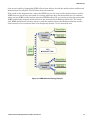
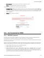
5.1
SNMP, MIB and RMON Groups
SNMP (Simple Network Management Protocol) and RMON (Remote Monitoring) provide a means to
monitor and manage your network. Each SNMP device maintains Management Information Bases
(MIBs) containing information about the operation and configuration of the device.
Note: This product uses Net-SNMP (available from www.net-snmp.org) which is subject to the
copyrights and license found at: http://www.net-snmp.org/COPYING.txt
The MIBs can be accessed with SNMP tools ranging from simple command-line tools like snmpwalk
and snmpget (part of the open source Net-SNMP package available at http://www.net-snmp.org) to
commercial network management products from various vendors. Key information from the MIBs is
also available via the switch's terminal and web interfaces.
The MIBs are divided into groups of related objects. Objects may be scalar (having only a single value)
or tabular (having a list of values varying over time, by port number, etc.).
For a list of the supported MIB and RMON groups, see Appendix D SNMP Support on page 150.
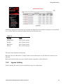
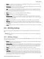
5.2
SNMP Security
SNMP provides several options for securing access to MIBs. SNMPv1 and SNMPv2 provide only weak
authentication. SNMPv3 uses encryption to add stronger authentication as well as privacy. In all versions, you may configure read-only and read/write users.
SNMPv1 and SNMPv2 authenticate users with a “community string” which is sent in clear text (unencrypted) and no password is required. Some measure of security can be achieved by setting long,
obscure community strings.
SNMPv3 provides three levels of security and encryption:
•
None–No password is required to read or write values in the MIB.
41
SNMP Notifications
•
Authentication–A password is required and is used to encrypt the user credentials so that security information is not sent in clear text. A variation of MD5 is used for encryption.
•
Privacy–A password is required and is used to encrypt the user credentials. A second password
is used to encrypt the details of the SNMP request using DES encryption.
For SNMPv3 access, the managed switch requires authentication and allows privacy. Only one password is configurable and it is used for both authentication and privacy.
The following examples use snmpget from the Net-SNMP tools to illustrate the use of authentication
and privacy when accessing the managed switch.
If SNMPv2 access is enabled, values may be read without a password with a command like:
snmpget -v 2c -c public 10.2.0.1 system.sysDescr.0
If SNMPv3 access is enabled, values may be read with a command like the following (entered all on one
line):
snmpget -v 3 -u public -l authNopriv -a MD5
-A publicpwd 10.2.0.1 system.sysDescr.0
Finally, if SNMPv3 access is enabled, an authenticated, private request could be made with a command
like the following:
snmpget -v 3 -u public -l authpriv -a MD5 -A publicpwd
-x DES -X publicpwd 10.2.0.1 system.sysDescr.0
The switch supports SNMPv1, v2, and v3. SNMPv1 and v2 access are essentially the same from a security standpoint and are enabled and disabled together. SNMPv3 security may be separately controlled.
Thus you may prevent unauthenticated access to your switch by disabling SNMPv1/v2 access entirely
while retaining password-secured access via SNMPv3.
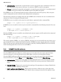
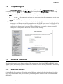
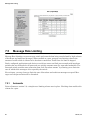
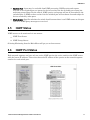
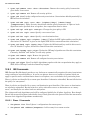
5.3
SNMP Notifications
Use the SNMP Notifications Menu to enable traps to be sent when the state of the switch changes.
Access this menu by selecting Setup from the Main Menu, and then selecting Main Settings.
Use the SNMP Notifications Menu to enable traps to be sent when the state of the switch changes.
Access this menu by selecting Setup from the Main Menu, and then selecting Main Settings.
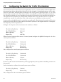
42
•
Authentication– Traps can be sent when invalid credentials (such as an unrecognized community string) are presented to the SNMP agent. Enable this setting to generate authentication
traps.
•
Topology change– Traps can be sent when the topology of the spanning tree changes. Enable this
setting to generate topology change traps.
•
Link 1 up/down-Link 18 up/down– Traps can be sent when a link goes up or down (the same
state reflected in the LED for each port). Enable these settings to generate link up/down traps.
Sixnet, LLC
Trap Managers
5.4
Trap Managers
Use the Trap Managers Menu to specify where traps will be sent. The Trap Managers Menu can be
accessed by selecting Setup from the Main Menu and then selecting Main Settings. Up to five trap
managers may be configured. For each one, the following values may be specified.
•
Host–The IP address of the host where the trap manager is located.
•
Community String–The community string to use when contacting the trap manager on the host.
•
Version–The SNMP trap version to send.
Note: There are two system traps that cannot be disabled and will be sent to any configured trap
managers. A coldStart trap will be sent whenever the SNMP agent starts up (usually, this is
only when the switch is reset). A NotifyRestart trap will be sent whenever the SNMP agent's
configuration changes and is reloaded. This will happen, for example, when you commit
changes on a configuration menu that includes SNMP settings.
5.5
Network Statistics
The Network Statistics page shows a subset of the performance data from SNMP and RMON. Select
RMON (Remote Monitoring) statistics or Ether-like statistics and the desired port number. The display
will be updated every 5 seconds.
5.5.1
Ether-Like Statistics
Selecting Ether-like statistics will display various Ethernet statistics for the selected port, for which
can be used to determine how your network is performing. These statistics come from the Dot3 MIB
(RFC 2665).
Industrial Ethernet Managed Switch Software User Manual
43
Network Statistics
The following statistics are provided:
•
Alignment Errors– Happens when the Ethernet Interface cannot synchronize with the incoming
packet because it is not of expected length (packet received has invalid CRC).
Causes: This is possibly caused by interference and attenuation. Check for faulty wiring, NICs,
or possible causes of interference/line noise.
44
•
FCS Errors–This error happens when packets have a bad Frame Check Sequence.
•
Single Collision Frames–This happens when an Ethernet device tries to send a frame but discovers that there is at least one other device on the network trying to send at the same time (collision detected). When a collision is detected the network devices prepare to access the network
medium again, but only after waiting for a random amount of time. Collisions are common in an
Ethernet network and collision detection allows the devices on an Ethernet network to work.
When the Ethernet device tries to transmit that same frame again and is successful, it is called
a single collision.
•
Multiple Collision Frames–Multiple collisions happen when the Ethernet device tries to transmit a frame through the network medium, but detects a collision. The Ethernet device tries
again to transmit the same frame through the network but again encounters another collision.
The error count is incremented each time a particular frame fails after the first attempt of
transmission.
•
SQE Test Errors–A network device checks for the Signal Quality Error Transmission to see if
the collision detection circuitry is working. For whatever reason that the network device does
not detect the SQE transmission, the SQE test error counter is incremented.
•
Deferred Transmissions–A transmission is deferred when a device is attempting to access the
network but another device is already transmitting (by detecting a carrier signal, not a collision)
on the network.
•
Late Collisions–When an Ethernet Device starts transmitting a frame on the network medium,
it believes that it can transmit because it didn't detect a collision. If for some reason the Ethernet device is transmitting, but after a given time period during the frame transfer it realizes
Sixnet, LLC
Network Statistics
that it really wasn't clear to transmit because it detected a collision; that is called a late collision. For a 10BASE-T network, a collision is detected (by the device that is transmitting that
frame) after 51.2 microseconds into a frame transfer is considered a late collision. For a
100BASE-T network, a collision is detected (by the device that is transmitting that frame) after
5.12 microseconds into a frame transfer is considered a late collision.
Causes: Late collisions usually come from a problem on the network such as improper configuration, compliance issues between network devices, incorrect cabling, and faulty Network Interface Cards.
•
Excessive Collisions–When an Ethernet Device attempts to transmit a frame but detects a collision, it attempts to retry to send the same frame at another random time. Should the Ethernet
device fail to transmit that particular frame after 16 tries, the Ethernet device gives up and the
frame will not be transmitted.
•
Internal MAC Transmit Errors–When frames fail to be transmitted correctly due to an internal
MAC sub-layer transmit error.
•
Carrier Sense Errors–When an Ethernet device loses the carrier sense condition whenever a
frame is being transmitted. The error is incremented a maximum of one time per transmission
attempt (no matter how many times the carrier sense condition fluctuates during a single transmission attempt).
•
Frame Too Longs–Every time there is a frame that is encountered to exceed the maximum
frame size.
•
Internal MAC Receive Errors–When frames fail to be received correctly due to an internal MAC
sub-layer receive error.
•
Symbol Errors–This happens when the system could not correctly decode a symbol that it has
received. Selecting RMON Statistics will display Remote Monitoring statistics for the selected
port that can be used to determine how your network is performing. These statistics come from
the RMON MIB (RFC 1757).
Industrial Ethernet Managed Switch Software User Manual
45
Network Statistics
5.5.2
46
RMON Statistics
•
Drop Events: A packet has been dropped due to insufficient switch resources.
•
Octets: # of data octets received.
•
Packets: # of packets received.
•
Broadcast Packets: # of broadcast packets received.
•
Multicast Packets: # of multicast packets received.
•
CRC Align Errors: # of packets received with an invalid CRC.
•
Undersize Packets: # of packets received less than 64 bytes with a valid CRC.
•
Oversize Packets: # of packets received more than 1536 bytes with valid CRC.
•
Fragments: # of packets received that are less than 64 bytes.
•
Jabbers: # of packets received more than 1536 bytes with invalid CRC.
•
Collisions: # of collisions detected.
•
64-octet Packets: # of packet of size 64 bytes received.
•
65-127-octet Packets: # of packets of 65 to 127 bytes received.
•
128-255-octet Packets: # of packets of 128 to 255 bytes received.
•
256-511-octet Packets: # of packets of 256 to 511 bytes received.
•
512-1023-octet Packets: # of packets of 512 to 1023 bytes received.
•
1024-1518-octet Packets: # of packets of 1024-1518 bytes received.
Sixnet, LLC
Port Mirroring
5.6
Port Mirroring
The mirroring option is ideal for performing diagnostics by allowing traffic that is being sent to and
received from one or more source ports to be replicated out a monitoring/target port. The Port Mirroring menu is accessed by selecting Setup from the Main menu, and then selecting Main Settings.
When enabling the port-mirroring feature, choose the source ports to be mirrored (monitored) and the
“sink” port to monitor their traffic. For each source port, choose to monitor messages being sent (select
Egress), messages being received (select Ingress) or messages being sent and received (select Both).
In the sample image above, port 4 is monitoring messages from port 2.
5.7
Alarm (OK) Output
The OK output can be configured to report a number of conditions by setting the Alarm output. This a
discrete output which will be high during normal conditions and low when an alarm is triggered. To
force the OK output to be always on, simply disable all alarm options.
•
Power Input Lost: In switches with redundant power inputs, an alarm condition will be triggered when power is not supplied to one of the inputs. This is the only alarm enabled by default.
•
Ring Failure: An alarm condition will be triggered when a ring failure occurs.
Ring failure on a local port will be triggered when one of this switch's neighbors in the ring goes
down; the general ring failure option will be triggered when any switch in the ring goes down.
The general ring failure option implies that local ring port failure is also detected.
•
No Carrier Detected (-MDM models only): An alarm condition will be triggered when there is no
carrier signal detected on the phone line (i.e., when the modem achieves carrier detect, the OK
output will be high).
Industrial Ethernet Managed Switch Software User Manual
47
Alarm (OK) Output
•
48
Ports Unlinked: Alarms can be configured for one or more ports, so that the OK output will be
low when one of the selected ports is unlinked.
Sixnet, LLC
Chapter 6 Redundancy Protocols
6.1
What Is RSTP?
The Rapid Spanning Tree Protocol (RSTP) allows you to have an Ethernet network with extra connections, so if one path between two points on the network fails, another path can be used to deliver messages. If one link or switch fails, another link or switch can take over transparently to prevent
unnecessary down time. So why not just physically connect each of the switches in your network in various loop configurations such that there are always at least two paths going to and from each switch? A
good idea, but it creates broadcast loops that will bring a network to its knees very quickly.
In an unmanaged Ethernet network there can be only one path between any two ports on the network.
If there is more than one path from one switch to another a broadcast message (and in some cases other
messages) sent by the network will be forwarded until it completes a loop by returning on the second
path. Since the switches forward all broadcasts and do not keep track of the messages they have sent,
the returning message will be sent around the loop again and again. A single message circulating forever around a loop at high speed is clearly not a good thing, so no loops are allowed.
The limitations of having only one path are even simpler to see. If the one and only path fails for any
reason, such as a broken cable or power failure at one of the switches, there are no paths left and no
network traffic can get through. We need a way to add alternate paths without creating loops. Thus the
use of Rapid Spanning Tree Protocol, a loop prevention protocol, is used such that switches can communicate with each other to discover and prevent loops.
In this diagram, the root ports are those connected directly to the root bridge because they have the
lowest port cost (only one hop). The paths that must go through another bridge (switch) have a higher
port cost (two hops) and are designated as backup ports. The ports connected directly to end stations
are assigned as edge ports so that RSTP doesn't waste time considering them.
49
What Is RSTP?
The Rapid Spanning Tree Protocol provides a standardized means for intelligent switches (also called
bridges) to enable or disable network paths so there are no loops, but there is an alternative path if it is
possible. Why is it called Rapid Spanning Tree Protocol?
•
‘Rapid’–it is faster than the previous (and completely compatible) version called Spanning Tree
Protocol (STP).
•
‘Spanning’– it spans (connects) all of the stations and switches of the network.
•
‘Tree’–its branches provide only one connection between two points.
In a Spanning Tree network, only one bridge (managed switch) is responsible for forwarding packets
between two adjacent LAN segments to ensure that no loops exist in a LAN. To ensure that only one
bridge is responsible, all other bridges on the network must cooperate with each other to form a logical
spanning tree that defines the pathways that packets should take from bridge to bridge.
The logical spanning tree has exactly one bridge that is assigned the role of root. All of the other
bridges need to have exactly one active path to the root. The job of the root bridge is to notify all bridges
connected in the tree that there has been a topology change and restructuring of the tree is in progress
(due to a communications link failure somewhere in the network). The root bridge is determined by the
bridge priority assigned to it and the MAC address.
By default, it is the bridge with the lowest MAC address that gets assigned the role as “root”, but a specific bridge can be forced to be the root bridge by changing its bridge priority setting (a lower number
with respect to other bridges means higher priority).
Every communication path between each bridge (managed switch) on the network has an associated
cost. This “path cost” may be determined by the speed of each segment, because it costs more time to
move data at a slower speed. The path cost can be configured to encourage or discourage the use of particular network. For example, you may not want to use a particular high-speed link except when absolutely necessary because there is a charge (money) for data using that path, while another path is free
(no monetary cost).
The root path cost is the cumulative cost of all the network paths from the root bridge to a particular
port on the network. A Spanning Tree network always uses the lowest cost path available between a
port and the root bridge. When the available network connections change, it reconfigures itself as necessary.
50
Sixnet, LLC
Recovery Time, Hops and Convergence
See the RSTP Examples topic in this section for an example of how the path cost can be utilized to
establish the primary and backup connections.
During the start-up of a Spanning Tree Network, all bridges (managed switches) are transmitting configuration messages (BPDUs) claiming to be the root. If a switch receives a BPDU that is “better” than
the one it is sending, it will immediately stop claiming itself as the root and send the “better” root information instead. Assuming the working network segments actually connect all of the switches, after a
certain period of time there will be only one switch that is sending its own root information and this
bridge is the root. All other switches transmit the root bridge's information at the rate of the root
bridge's “hello time” or when the root bridge's BPDU is received on one of their ports.
The only factor for determining which switch is the root (has the “best” root information) is the bridge
priority and its tie-breaker, the switch MAC address. If a switch has more than one path to get messages from the root, other information in the configuration message determines which path is the best.
Once the root bridge is determined, all other switches see the root bridge's information and information
about path (or paths) to the root. If more than one port provides a path to the root the non-root switches
must decide which port to use. They check all of their ports to select the port that is receiving messages
indicating the best path to the root.
The selected port for each bridge is called the root port. It provides the best path to communicate with
the root. The best path is determined first by the lowest total path cost to the root (root path cost). Each
port is assigned a cost (usually based on the speed) for messages received on that port. The root path
cost for a given path is just sum of the individual port costs for that path. The lowest path cost indicates
the shortest, fastest path to the root. If more than one path has the same cost the port priority assigned
to each port, and its tie-breaker the port number pick the best path.
6.2
Recovery Time, Hops and Convergence
The typical RSTP recovery time (time to start forwarding messages on the backup port) on a link-loss
failure is <50 mS per “hop” (firmware version 3.1 or higher). A hop is defined as a link between two
switches. A link to an end station is not considered a hop.
The Max Age setting controls how long RSTP messages may circulate in the network. Since the largest
value allowed for Max Age is 40, the largest RSTP network hop-diameter is also 40.
See the RSTP Examples topic in this section for a more detailed explanation about hops and recovery
time.
The time it takes for all of the switches to have a stable configuration and send network traffic is called
the convergence time. STP was developed when it was acceptable to have a convergence time of maybe
a minute or more, but that is not the case anymore. Due to the increased demand for better convergence times, Rapid Spanning Tree Protocol was developed, bringing the normal convergence time for a
properly configured network down to a few seconds. The RSTP takes advantage of the fact that most
modern Ethernet links between switches are point-to-point connections. With a point-to-point link, the
switches can quickly decide if the link should be active or not.
Industrial Ethernet Managed Switch Software User Manual
51
Spanning Tree Settings
6.3
Spanning Tree Settings
The Spanning Tree Settings enable you to choose the redundancy protocol and set parameters related
to that protocol.
To access the Spanning Tree Settings, choose Managed Switch Menu>Main Settings>Setup>Redundancy Settings>Spanning Tree Settings.
6.3.1
Redundancy Protocol (Default = Rapid Spanning Tree Protocol)
Choose the protocol by selecting STP (Spanning Tree Protocol), RSTP (Rapid Spanning Tree Protocol)
or MSTP (Multiple Spanning Tree Protocol). A selection of None will disable this advanced feature.
Choosing STP, RSTP or MSTP will allow the wiring of redundant networks (such as rings) for automatic failover. RSTP is compatible with STP so in most cases you can just choose RSTP. Only choose
STP if you want to force the switch to only use this protocol. STP/RSTP/MSTP use BPDUs (Bridge Protocol Data Units) to keep bridges informed of the network status.
MSTP is compatible with RSTP and STP but adds the ability to route VLANs over distinct spanning
trees within an MSTP region. In order to configure the spanning trees, you must create spanning tree
instances using the STP configuration page and assign VLANs to them using the VLAN configuration
page.
MSTP falls back to RSTP behavior outside of an MSTP Region. A region is identified by the unique
combination of Region Name, Configuration Revision and VLAN to MSTI mapping for each switch in
that region. If those values match for linked switches running MSTP, those switches consider themselves to be in the same region.
Caution: If VLANs and redundancy (STP/RSTP/MSTP) are both enabled, situations can arise
where the physical LAN is intact but one or more VLANs are being blocked by the redun-
52
Sixnet, LLC
Spanning Tree Settings
dancy algorithm and communication over those VLANs fails. The best practice is to make
all switch-to-switch connections members of all VLANs to ensure connectivity at all times.
Select none if you do not require the switch to manage redundant network connections. All ports will
forward network traffic just as an unmanaged switch would. Otherwise RSTP (Rapid Spanning Tree
Protocol) should usually be selected. A selection of STP or RSTP will allow redundant links between
switches so those links can keep the network connected even when a primary link fails. RSTP is compatible with switches that only implement plain STP, an older version of the protocol. If STP is selected
only the original STP format messages will be generated. Selecting STP reduces the chances of network
packets being duplicated or delivered out of order, but at the expense of much longer reconfiguration
time.
Note: Should you intend to use RSTP and VLANs at the same time, please see 9.4 VLAN with
RSTP on page 84 for important information concerning the setup of your network. Otherwise,
communication failures may occur.
6.3.2
Bridge Priority (0 to 61440; Default = 32768
The bridge priority is used to determine the root bridge in the spanning tree. (For MSTP, the bridge priority is used to determine the CIST root.) The priority ranges from 0 to 61440 (default 32768) and must
be a multiple of 4096. Lower numbers indicate a better priority.
By default, the bridge with the lowest bridge priority is selected as the root. In the event of a tie, the
bridge with the lowest priority and lowest MAC address is selected.
There are two ways to select a root bridge (switch). The first is to leave all the bridge priority settings
at the default setting of 32768. When all the switches are set at the default priority, the managed
switch with the lowest MAC address is selected as the root. This may be adequate for networks with
light or evenly distributed traffic.
The second way to select a root bridge is to customize priority settings of each bridge. Customizing the
bridge priority settings allows the network to select a root bridge that gives the best network performance. The goal is generally to have the network traffic pass through the network as directly as possible, so the root should be central in the network. If most messages are between one central server and
several clients, the root should probably be a switch near the server so messages do not take a long
path to the root and another long path back to the server.
Once you decide which switch should be the root, it should be given the best (numerically lowest) bridge
priority number in the network.
6.3.3
Maximum Age (6 to 40; Default = 20)
For STP, the max age indicates the maximum time (in seconds) that the switch will wait for configuration messages from other managed switches. If that time expires, the switch assumes that it is no longer connected to the root of the network. If a link goes down in a way that the switch can detect as loss
of link, it does not wait before reconfiguring the network.
RSTP waits 3 times the Hello Time instead of Max Age before assuming that it is no longer connected
to the root of the network. However, Max Age is used to limit the number of hops Spanning Tree information may travel from the root bridge before being discarded as invalid. Furthermore, MSTP only
counts hops that take place to or from switches outside the MSTP region for this check. The value of
Max Hops (below) is used to limit hops within an MSTP region.
Note: Assign all switches in an RSTP/STP network the same max age.
Industrial Ethernet Managed Switch Software User Manual
53
Spanning Tree Settings
The maximum age must satisfy the following constraints:
2 × (hello time + 1.0 seconds) < max message age < 2 × (forward delay - 1.0 seconds)
6.3.4
Hello Time (1 to 10; Default = 2)
Configuration messages (BPDUs) are either sent periodically to other bridges based on a time period
labeled hello time. Decreasing the hello time gives faster recovery times; increasing the hello time
interval decreases the overhead involved.
The hello time must satisfy the following constraints:
2 x (hello time + 1.0 seconds) < max message age < 2 x (forward delay - 1.0 seconds)
6.3.5
Forward Delay (4 to 30; Default = 15)
The forward delay is a time (in seconds) used by all switches in the network. This value is controlled by
the root bridge and is used as a timeout value to allow ports to begin forwarding traffic after network
topology changes. If a port is not configured as an edge port and RSTP cannot negotiate the link status
a port must wait twice the forward delay before forwarding network traffic. In a properly configured
network using RSTP (not STP) this setting has very little effect. For STP networks, setting the time too
short may allow temporary loops when the network structure changes (switches turn on or off or links
are added or broken). A longer time will prevent temporary loops, but network traffic will be disrupted
for a longer time.
The default value for the forward delay is 15 seconds. If you change this setting, the switch will not
allow a value unless it satisfies the following formula:
2 × (hello time + 1.0 seconds) < max message age < 2 x (forward delay - 1.0 seconds)
6.3.6
Transmission Limit (1 to 10; Default = 6)
The transmission limit controls the maximum number of BPDUs that can be sent in one second.
The transmission limit can range from 1 to 10 messages/second (6 messages/second default). Increasing
Transmission limit can speed convergence of the network but at the cost of configuration messages
using a larger share of the available network bandwidth.
6.3.7
Region Name (MSTP)
The region name is used together with the configuration revision and VLAN to MSTI mapping to define
an MSTP region.
6.3.8
Configuration Revision (MSTP; 0 to 65535)
The configuration revision is used together with the region name and VLAN to MSTI mapping to define
an MSTP region.
6.3.9
Max Hops (MSTP; 6 to 40; Default = 20)
Max Hops determines the maximum number of switches a BPDU will be propogated through within an
MSTP region. This value is used to prevent old data from endlessly circulating within a region.
54
Sixnet, LLC
Spanning Tree Port Settings
6.3.10
MST Instances
For MSTP, you can configure multiple spanning tree instances. Add an instance by clicking Add MSTI.
For each MSTI, you can configure a name, the MST ID, and this bridge’s priority in that spanning tree
instance.
6.4
Spanning Tree Port Settings
Each port can be configured to tune the STP/RSTP/MSTP spanning tree. With MSTP, each spanning
tree instance can be tuned independently.
Using MSTP, you can configure separate port settings for the CIST (Common Internal Spanning Tree)
and for every spanning tree created by MSTP. Settings for individual MSTIs (Multiple Spanning Tree
Instances) only affect ports connected to switches within the same MSTP Region.
By default, MSTIs inherit their settings from the CIST. To configure an MSTI individually, you must
select it from the drop-down box and click the Customize button for the instance. Click Inherit if you
want a spanning tree's values to be inherited from the CIST again.
To access the Spanning Tree Port settings, choose Managed Switch Menu>Main Settings>Setup>
Redundancy Settings>Spanning Tree Port.
The next sections explain each of the port settings.
Industrial Ethernet Managed Switch Software User Manual
55
Spanning Tree Port Settings
6.4.1
Exclude (Default = Included)
Normally all ports should be included in determining the Spanning Tree network topology, either as a
normal port or an edge port. It is possible to completely exclude a port, so that it will always forward
network traffic and never generate or respond to network messages for RSTP or STP. Excluding a port
is an advanced option that should be used only if absolutely necessary.
This option excludes the port from all spanning tree instances and appears with the other CIST settings.
6.4.2
Port Priority (0 to 240; Default = 128)
Selection of the port to be assigned “root” if two ports are connected in a loop is based on the port with
the lowest port priority. If the root bridge fails, the bridge with the next lowest priority then becomes
the root.
This option may be set per port per MSTI.
If the switch has more than one port that provides a path to the root bridge and they have the same
root path cost, the selection of which port to use is based on the port priority. The port with the best
(numerically lowest) priority will be used. If the port priority is the same, the switch will use the lowest
numbered port. The port priority can range from 0 to 240 seconds (128 second default).
6.4.3
Path Cost (1 to 200,000,000)
As with any network, there is an associated cost to go from a source location to a destination location.
For RSTP, the root path cost is calculated based on the bandwidth available for that particular connection to the root bridge. The port with the lowest cost for delivering messages to the root is used to pass
traffic toward the root.
The path cost can be assigned automatically based on the port speed, using the IEEE standard values
of 200,000 for 100Mbps links and 2,000,000 for 10Mbps links, or the value can be specified in the range
1 to 200,000,000.
The default value depends on the capabilities of the port: 200,000 for 100 Mbps and 20,000 for 1000
Mbps ports.
This option can be set per port per MSTI.
See 6.8 RSTP Examples on page 59 for an example of how the path cost can be utilized to establish the
primary and backup connections.
6.4.4
Type (Default = Auto)
A port that connects to other switches in the network may be part of a loop. To ensure such loops do not
occur, the switch will not put a port in the Forwarding state until enough time has passed for the spanning tree to stabilize (twice the forwarding delay, 30 seconds by default). However, if a port connects
directly to a single device at the edge of the network, it may safely be put in Forwarding state almost
immediately. The port Type controls the switch's assumptions about what is connected to the port.
•
56
Auto: The port will initially be assumed to be an Edge port and go to Forwarding quickly. It will
automatically adjust to being a Network port if BPDUs are received and revert to being an Edge
port any time no BPDUs are received for 3 seconds.
Sixnet, LLC
Redundancy Status
•
Network: The port will always wait a safe time before going to the Forwarding state.
•
Edge: The port will initially be assumed to be a direct connection to a single device but will
change to being a Network port if any BPDUs are received. Thereafter, it will always wait a safe
time before going to Forwarding whenever a link is reestablished on the port.
This option can be set per port per MSTI.
6.4.5
Port-to-Port MAC (Default = Auto)
A port is part of a point-to-point network segment when there can be no more than one other network
port connected to it. RSTP can decide whether it is safe to forward network traffic very quickly on
point-to-point links to other managed switches, otherwise the port must wait many seconds (30 seconds
by default, twice the forward delay) before forwarding network traffic. When set to Auto, full-duplex
links are assumed to be point-to-point, half-duplex ports are not. This setting can be forced true or false
if the automatic determination would be wrong.
6.5
Redundancy Status
The Redundancy Status page, accessed through the Monitoring Menu from the Main Menu, provides a
snapshot of the switch and its role in the managed network. At the top of the page, the protocol in use
is displayed along with the MAC address of the current root of the spanning tree. The topology change
counter will track the number of changes to the network layout. Also, the current redundancy status of
each port on the switch is displayed.
Industrial Ethernet Managed Switch Software User Manual
57
Port States for the STP Algorithm
•
Port: The number of the port. This corresponds to the labels on the switch.
•
Name: The user-configured name of the port.
•
Status: The configured state of the port in the STP protocol (included or excluded). An included
port is part of the managed network and may carry traffic to other managed switches for other
devices. An excluded port will not be used as part of the managed network. For example, a single uplink from a managed network of factory devices to a business network would be configured
to be excluded from STP use.
•
State: The STP/RSTP state of the port (see below).
•
Cost: The cost of using this port to reach other parts of the managed network.
•
STP/RSTP Port States: In Spanning Tree Protocol, there are five port states. Rapid Spanning
Tree Protocol uses just three. Table 1-1 and Table 1-2 show port states, port participation in the
active Spanning Tree Topology, and port participation in learning MAC addresses for STP and
RSTP respectively. All ports that are not physically connected to an Ethernet device or have a
faulty connection will be labeled as “unlinked” in the port state section.
6.6
58
Port States for the STP Algorithm
•
Blocking (STP): A port in this state does not participate in frame relay (pass frames received to
other locations). Once a port is in this state, it is prevented from the possibility of frame duplication caused by multiple paths in an active topology.
•
Listening (STP): A port in this state is about to participate in frame relay, but is not involved in
any relay of frames (no frames will be forwarded). The reason for not entering frame relay
immediately is to ensure that there are no temporary loops introduced when the network topology is changing. During this state, the bridge will disable all learning states on its ports to prevent the race conditions when ports are changing roles and the forwarding process will discard
all frames and not submit any frames for transmission. Meanwhile BPDUs can still be received
and forwarded to keep the algorithm running.
•
Learning (STP): A port in this state is about to participate in frame relay, but it is not involved
in any relay of frames. Frame relays are not performed to prevent the creation of temporary
loops during the active topology of a changing bridged LAN. In addition, the forwarding process
will discard all frames and not submit any frames for transmission. The reason for enabling
learning is to acquire information prior to any frame relay activities. Information gathered will
be used and placed in the filtering database (MAC table) to reduce the number of frames being
unnecessarily reduced.
•
Forwarding (STP): A port in the forwarding state is currently participating in frame relay.
BPDUs will include the forwarding port in the computation of the active topology. BPDUs
received are processed according to the Spanning Tree algorithm and transmitted based on the
hello time or BPDU information received.
Sixnet, LLC
Port States for the RSTP Algorithm
Table 6-1 801.1D STP Port States
Port States
Port Participates in
Active Topology
Port Participates in
Learning MAC Addresses
Disabled
No
No
Blocking
No
No
Listening
Yes
No
Learning
Yes
Yes
Forwarding
Yes
Yes
6.7
Port States for the RSTP Algorithm
To optimize the efficiency of 802.1D spanning tree protocol, certain states were condensed or eliminated
to produce faster convergence times. Specifically, the disabled, blocking, and listening states in STP
have been reduced down to a single discarding state in RSTP.
•
Discarding State (RSTP): In this state, station location information is not added to the Filtering
Database (MAC table) because any changes in port role will make the Filtering Database information inaccurate.
•
Learning State (RSTP): In this state, information is being added to the Filtering Database
under the assumption that the port role is not changing. Gathering information before frame
relay (forwarding state) will reduce the number of frames sent out when entering the forwarding state.
•
Forwarding State (RSTP): Frames will be forwarded to and from the particular port that is in
the forwarding state. In addition, during the forwarding state, the learning process is still incorporating station information into the filtering database.
Table 6-2 802.1D RSTP Port States
Port States
Ports Participating
in Active Topology
Ports Participating in
Learning MAC Addresses
Discarding
No
No
Learning
No
No
Forwarding
Yes
Yes
6.8
RSTP Examples
6.8.1
Example 1: Maximum “Hops” and Switches in a Redundant Ring
The Max Age setting controls how long RSTP messages may circulate in the network. When a switch
receives a message, it compares the age of the message with the Max Age (also carried in the message)
and if the age has reached the Max Age, the message is discarded. Otherwise, the message age is increIndustrial Ethernet Managed Switch Software User Manual
59
RSTP Examples
mented before the message is forwarded. Therefore, the maximum diameter of a RSTP network is controlled by Max Age. Since the largest value allowed for Max Age is 40, the largest RSTP network hopdiameter is also 40.
6.8.1.1
Number of Hops vs. Recovery Time
The diagram below shows a typical redundant ring network with 6 managed switches and 5 hops
between stations.
The overall recovery time when there is a network segment failure is dependent on the number of hops.
The recovery time is typically less than 50 mS per hop. Therefore, in the diagram below of a typical ring
with 6 managed switches the overall recovery time would be less than 250 mS (5 hops x <50 mS).
Figure 6-1 Typical Redundant Ring with Five Hops Between A and B
6.8.2
Example 2: Using Path Costs to Establish Primary & Backup
Connections
The path cost can be used to distinguish the best connections to use. You can assign a higher cost to
pathways that are more expensive, slower or less desirable in any way. The managed switches will then
add up the path costs to determine the best route back to the root switch. See the example below.
Note: In most networks you may leave the path costs set to the default settings and allow the
switches to automatically determine the best paths.
60
Sixnet, LLC
RSTP Examples
6.8.3
Example 3: Ring Topology with only one Managed Switch (Do not do
this!)
Implementing a ring topology with a single managed switch and several unmanaged switches is a common question because of the thought of saving money. The topology is legal only if that single managed
switch is a member of each ring. Although it is legal, it is not recommended, as the hypothetical scenario indicated below will explain why.
6.8.3.1
Hypothetical Scenario
An integrator wishes to use implement a single Ethernet ring topology for the proposed network. Only
one managed switch is used to connect to three or more unmanaged switches in the loop (Figure 1).
Industrial Ethernet Managed Switch Software User Manual
61
RSTP Examples
Initially, everything is working fine in the network. The managed switch detects the loop by seeing its
own configuration messages and based on STP parameters, chooses one port to be in the forwarding
state, and the other port to be in the blocking state. No loop is formed and device A can talk to device B.
Somewhere in the plant, a construction vehicle accidentally cuts the connection between unmanaged
switch #1 and unmanaged switch #2. The managed switch in the network notices (typically around 6
seconds when connected to an unmanaged switch) that the port in blocking mode is not receiving configuration messages and transitions through the listening, learning, and forwarding states (Figure 2).
This would seem to have solved the problem as both ports in the managed switch are in forwarding
mode, but it is not the case. Due to the fact that the other three switches are unmanaged, they do not
have the intelligence to know that there has been a change in the network topology. Switch #1 still
points to switch #2 when device A is trying to talk to device B (for which it cannot, due to the broken
62
Sixnet, LLC
Real-Time Ring Settings
Ethernet link). The bottleneck has been discovered, as we have to wait until the MAC table in switch
#1 ages out its entries of device A and device B. The same applies for devices connected to switch #2 (B
talking to A) and switch #3 (C talking to A).
As a result of this “money saving” configuration, the network redundancy performance is traded off and
left at the mercy of the time it takes to age out MAC table entries in switches 1, 2, and 3. Depending on
the model of unmanaged Ethernet switch, entries in the MAC table are usually aged out in a time
period of 5 minutes or more.
This introduces at least 5 minutes of downtime for the plant, which could have a very detrimental cost
with respect to the operation of the plant. By replacing switches 1, 2, and 3 with managed switches, the
network convergence time is brought down to a less than a second. An additional benefit is that the network is not limited to only one redundant loop and can have a “mesh” of connections for a truly redundant network scheme at all points in the network.
6.9
Real-Time Ring Settings
The Real-Time Ring Settings page, accessed through the Redundancy Settings, allows configuration of
Sixnet's Real-Time Ring protocol in supported switches.
A real-time ring increases network reliability by providing an alternative path for message flow in the
event of a network segment failure. When a ring port detects a communications break, it quickly notifies the other switches in the ring. Messages are automatically rerouted through the alternative ring
path within milliseconds.
STP (Spanning Tree Protocol) is more flexible than a ring configuration, but recovery times for spanning trees may be in the hundreds of milliseconds. The real-time ring protocol exchanges topological
flexibility for recovery times in the tens of milliseconds.
6.10
Ring Setup
Activate a ring by selecting the appropriate Enable check box. You can configure one ring for every two
ports on the switch.
When a ring is enabled, be sure to choose the two ports being used to connect the switch into that particular ring. To do so, simply pick the available ports from the Primary Port and Backup Port dropdown lists. Each port should be assigned to only one ring.
The port defined as Backup will be blocked under normal operating conditions. By default, the switch
with the lowest numbered MAC address in a ring will be the master switch, meaning that the communication in the ring will be blocked from one of the two ring ports of that switch. Only the master switch
in a ring does this. You may designate a different switch as the master switch by choosing “This is Master” from the Ring Master dropdown list for the desired switch. All other switches in the ring should be
set to the default “Automatic” setting.
Note: When a port is configured as a Ring port, that port cannot be used for communication to or
through the switch. It can ONLY be connected to another Ring port on a managed switch or
Real-Time Ring switch.
Industrial Ethernet Managed Switch Software User Manual
63
Ring Setup
64
Sixnet, LLC
Chapter 7 Priority Queuing (QoS, CoS, ToS/DS)
7.1
Traffic Priority
Without enabling special handling, a network provides a “best effort” service to all applications. This
means that there are no assurances regarding the Quality of Service (QoS) for any particular application because all packets are treated equally at each switch or router. However, certain applications
require deterministic response from the network to assure proper operation.
Consider a drilling machine in a plant that is controlled by a computer elsewhere on a local network.
The depth of the machine's drill is critical; such that if the hole is drilled is too deep, the material will
have to be thrown out. Under nominal conditions, the drill process is running smoothly (controller and
computer are communicating efficiently over the network) but when another user on the network
decides to access records from an online database, the large volume of traffic can interfere with timely
communication with the drill. A delay in communications between the drill and controller causes the
drill to go too far and the material has to be thrown away. To prevent this from happening, we need to
provide a certain QoS for all drill-controller communications so delay is avoided.
Numerous mechanisms exist to help assure reliable and timely network communication. The managed
switch supports two common means of prioritizing messages: IP header and 802.1p user priorities.
The IP header is present in all frames and contains a priority field, which defaults to 0 and may be set
as high as 255. This field is sometimes referred to as the Type of Service (ToS) field, or the Differentiated Services (DS or DiffServ) field.
Applications may add IEEE 802.1p tags, which contain a priority field that may be set from 0 to 7. Each
value has a traffic type associated with it. For example, a tag of 5 is prescribed for video data.
The switch provides four priority queues for expediting outbound data. The 256 IP priorities and the 7
IEEE priorities are mapped into these ports in a way that optimizes throughput of high priority data.
65
Scheduling
7.2
Scheduling
When choosing how to handle lower priority data, the switch can use strict or fair scheduling. This
choice affects all queues on all ports.
With strict scheduling, all data in the highest priority queue will be sent before any lower priority data,
then all data from the second highest priority, and so on. This assures that high-priority data always
gets through as quickly as possible.
With fair scheduling, a round-robin algorithm is used, weighted so that more high-priority than lowpriority data gets through Specifically, the switch will send eight frames from the urgent queue, then
four from the expedited queue, two from the normal queue, and one from the background queue, then
start over with the urgent queue. This assures that the lower priority queues will not be starved.
7.3
QoS / CoS Settings
Access to the switch's traffic priority menus can be done by selecting Setup from the Main Menu, and
then Traffic Priority.
For each port, the following settings may be configured:
66
•
Use 802.1p Tag Priority: This setting controls whether the switch will honor IEEE tags if present in frames. When enabled, tagged data will be routed to an outbound priority queue based on
the configure tag mapping (See below). Disable this setting to ignore IEEE tags on all in-coming
frames.
•
Use IP ToS/DiffServ: This setting controls whether the switch will honor priority fields in the IP
header. When enabled, and not overridden by an IEEE tag, data will be routed to an outbound
priority queue based on IPv4 Type of Service or IPv6 Traffic Class. The priority queue will be the
IP priority field value divided by 64. Disable this setting to ignore IP priority fields.
Sixnet, LLC
802.1p Tag Settings
•
Priority Precedence: This setting controls which priority mark — IEEE tag or IP header —
takes precedence if both are present and enabled. It has no effect if either Use Tags or Use IP is
disabled.
•
Default Priority: This setting controls the default priority to be assigned to frames when it cannot otherwise be determined. For example, if a frame without an IEEE tag arrived at a port
where Use IP was disabled. Select an out-bound priority queue from the list.
•
Port Type: This setting controls how IEEE tags are handled in out-going data:
7.4
•
Transparent maintains any tag that may have been present in a frame when it entered the
switch.
•
Edge removes tags from all out-going frames.
•
Network adds a tag if none is present. The value of the tag is the queue number times two
(six for queue 3, etc.)
802.1p Tag Settings
Each of the 8 IEEE tag priority values can be assigned to one of the four output priority queues:
•
Background (0)
•
Normal (1)
•
Expedited (2)
•
Urgent (3)
The default assignment follows the IEEE 802.1p recommendation as follows:
Table 7-1 Default Tag Assignments
Priority
Traffic Type
Queue
0
Best Effort
1
1
Background
0
2
Spare
0
3
Excellent Effort
1
4
Controlled Load
2
5
Video
3
6
Voice
3
7
Network Control
3
Industrial Ethernet Managed Switch Software User Manual
67
Message Rate Limiting
7.5
Message Rate Limiting
Message Rate Limiting can prevent your switch and network from being overwhelmed by high volumes
of broadcast and multicast messages. When enabled on a port, message rate limiting controls the
amount of traffic which is allowed to be bradcast or multicast. Traffic over the limit is dropped.
Poorly configured applications and devices or malicious users can flood your network with broadcast
packets that are forwarded to all ports and can quickly consume most of a network's bandwidth. The
managed switch provides some protection from such “broadcast storms” by allowing you to limit the
rate at which these messages are accepted by the switch.
For each port, you may choose to limit the rate of broadcast and multicast messages accepted. Messages over the preset limit will be discarded.
7.5.1
Automatic
Prior to firmware version 5.2, a simpler rate limiting scheme was in place. Checking Auto enables this
scheme for a port.
68
Sixnet, LLC
Message Rate Limiting
Limiting is done based on message type and priority. Broadcast and multicast messages are prioritized
(e.g., by IP to ToS) then limited to approximately the following rates:
Table 7-2
Priority
Limit
Background
10% of link capacity
Normal
20% of link capacity
Expedited
40% of link capacity
Urgent
80% of link capacity
The exact limit depends on link speed.
Messages directly addressed to a single station (unicast messages) are not affected by message rate
limiting.
With Auto unchecked the new, more flexible scheme is possible as detailed below.
7.5.2
Ingress Limiting
Traffic entering the switch can be controlled by type, rate and priority.
Industrial Ethernet Managed Switch Software User Manual
69
Message Rate Limiting
Types
Ingress rate limiting can be applid to different types of traffic:
•
All types
•
Broadcast, multicast and flooded unicast (Frames with known unicast addresses are not
affected.)
•
Broadcast and multicast (Frames with unicast addresses are not affected.)
•
Broadcast (Frames with multicast or unicast addresses are not affected.)
Rate
Ingress traffic may be limited in steps. The user can select from a list of supported percentage values,
depending on the type of port. 100Mbps ports have arange from 5% to 80%. Gigabit (1000Mbps) ports
have a range of 1% to 25%. Both have increments based on rates best supported by the underlying
hardware.
Priority Shaping
The configured Rate applies to Background traffic. Each successively higher priority may use the same
rate (when shaping is disabled) or twice the limit of the next lowest (when shaping is enabled).
7.5.3
Egress Limiting
Egress traffic may be limited in steps. The user can select from a list of supported percentage values,
depending on the type of port. 100Mbps ports have a range from 5% to 80%. Gigabit (1000Mbps) ports
have a range of 1% to 25%. Both have increments based on rates best supported by the underlying
hardware.
70
Sixnet, LLC
QoS Example
Egress rate limiting applies to all types of traffic (unicast, broadcast and multicast).
7.6
QoS Example
7.6.1
QoS Ensures Real-Time Delivery of Important Messages
Let us investigate a detailed example of how to manage a network such that critical real time data will
not be interrupted by data that is not as urgent (relatively speaking). Consider the following:
7.6.2
Hypothetical Scenario
Scenario: There is a power plant that is controlled by a central control system. In addition, because of
security concerns, cameras have been mounted and installed at each location of mechanical control.
The mechanical control devices and video cameras at each site communicate via Ethernet to their own
switch. (For reasons of simplicity and clarity, we will assume that only video and control data reside on
the network)
Problem: Should any of the mechanical control devices receive delayed control data from the central
control system, the power plant can't generate the maximum energy that it is capable of. Customers
will experience brown outs, and the plant will be looked upon with negative scrutiny. It is therefore
very important that the video traffic created by the cameras not delay critical data.
Goal: To optimize the forwarding of critical real-time control data and minimize or eliminate the impact
of video data traversing the network at the same time.
Solution: Configure the switch such that video data has lower priority than control data by adjusting
the priority queuing settings in the switch.
Industrial Ethernet Managed Switch Software User Manual
71
Configuring the Switch for Traffic Prioritization
7.7
Configuring the Switch for Traffic Prioritization
As mentioned earlier in this manual, some applications require a certain Quality of Service (QoS) from
the network to achieve a desired level of service. In this example, it is important that we achieve timeliness for control data. Without taking advantage of the switch's priority queuing abilities, we are using
the best-effort network model. This means that the network will try to deliver all packets of information, but will not make any sort of promise or guarantees with respect to the timeliness of data for specific applications. Considering our control/video example, there is no guarantee that we can get the
response time needed for control data if the video cameras are sending data at the same time.
A way to achieve the QoS desired is to prioritize network traffic. Prioritization of network traffic can be
achieved even if the devices (video cameras and control systems) do not support selection or configuration of Quality of Service parameters.
Configure all the ports used to interconnect the switches as follows:
Use 802.1p Tag Priority
Checked
Use IP ToS/DiffServ
Checked
Default Priority
Tag
Output Tag
Add Tag
Where the data originates (the camera or control system), configure the QoS/CoS settings for the video
camera ports as follows:
Use 802.1p Tag Priority
Unchecked
Use IP ToS/DiffServ
Unchecked
Default Priority
Expedited
Output Tag
Remove Tag
Also, configure the control system ports as follows:
Use 802.1p Tag Priority
Unchecked
Use IP ToS/DiffServ
Unchecked
Default Priority
Urgent
Output Tag
Remove Tag
In this way, the switches will handle the packets appropriately and tag them for handling elsewhere in
the network.
At the destination, configure the control system port as follows:
Use 802.1p Tag Priority
Checked
Output Tag
Remove Tag
Also, configure the video concentrator port as follows:
72
Sixnet, LLC
Result
Output Tag
7.8
Remove Tag
Result
Result: Configuring the video data to have a lower priority than control data results in the QoS
required for the control data.
In the diagram below, we have an IPm controlling a turbine and some torque converters. In addition,
we have a video concentrator device that is collecting video data. Since the switch was configured such
that video data (Triangles) has lower priority than control data (circles), we see that the control data
gets sent out more often than the video data. For clarity, the diagram notes that untagged data in the
network consists of open triangles and circles, while tagged data in the network consists of filled triangles and circles. This achieves the QoS needed for the control application.
Industrial Ethernet Managed Switch Software User Manual
73
Chapter 8 Multicast Filtering (IGMP)
8.1
About IGMP
IGMP (Internet Group Management Protocol) allows hosts and routers to work together to optimize
forwarding of multicast traffic on a network. Without IGMP, all multicast packets must be forwarded to
all network segments. With IGMP, multicast traffic is only forwarded to network segments, which connect interested hosts.
IGMPv1 provides a basic mechanism for hosts and routers to communicate about multicast groups.
Routers send Query messages and hosts respond with group membership Report messages.
IGMPv2 adds a maximum response time to the Query and adds a Leave message to the protocol.
IGMPv1 and IGMPv2 should not coexist on the same network. Also, IGMPv2 routers are expected to
perform IGMPv1 on segments where IGMPv1 hosts are found.
An IGMP snooping switch performs many of the functions of an IGMP router. In passive mode, such a
switch processes IGMP protocol messages sent by hosts and routers to configure efficient forwarding of
multicast traffic. In active mode, a switch will also send its own queries to speed network convergence.
Periodically, routers and IGMP snooping switches in active mode send an IGMP Query on each
attached network. (The query interval is generally around 1-2 minutes.) A host that wishes to be a
member of a group sets a timer for a short, random delay when it sees the Query. If it sees a Report
from another host before its timer expires, it cancels the timer and takes no further action until
another Query is seen. If no other Report is seen, a Report is sent when the timer expires. The router or
switch uses the Report to configure multicast forwarding.
The router or switch keeps track of how long it has been since the last Report on each port for each
group. When the group expires, the router or switch stops forwarding multicast data to that port. Since
the query interval is less than the expiration time, data for active groups continues to be forwarded
without interruption
74
Multicast Filtering Configuration
8.2
Multicast Filtering Configuration
IGMP can be configured through two menus:
•
IGMP Switch Settings
•
IGMP Port Settings
Selecting Setup from the Main Menu and then selecting Multicast Filtering will get you to these
menus.
8.3
•
•
IGMP Switch Settings
IGMP Mode: This setting controls how the switch handles IGMP messages to determine how to
forward multicast traffic.
•
IGMP Disabled causes the switch to ignore IGMP messages. All multicast traffic will be sent
to all ports.
•
Passive IGMP handling causes the switch to listen to IGMP messages and configure forwarding of multicast traffic accordingly.
•
Active IGMP handling causes the switch to act as an IGMP router, sending queries when
needed and configuring multicast forwarding according to IGMP membership reports.
Multicast Suppression: This enhanced feature can intelligently suppress multicast packets that
no host has requested with IGMP.
Industrial Ethernet Managed Switch Software User Manual
75
IGMP Port Settings
•
None–Multicast packets will be sent to all ports unless IGMP is enabled and one or more clients have sent IGMP Report requests.
•
IP multicast groups–Multicast packets corresponding to IP multicast groups (with MAC
addresses starting 01:00:5e) will be suppressed unless one or more clients have sent IGMP
Report messages. Multicast packets with other addresses will be sent to all ports.
•
All unreserved multicast–Multicast packets with reserved multicast addresses
(01:80:c2:00:00:0x where x is 0..f) will be sent to all ports. All other multicast packets will be
suppressed unless one or more clients have sent IGMP Report messages.
•
IGMP Version: This setting controls the highest IGMP version that the switch will use. All
IGMP routers and snooping switches on a network should be configured for the same IGMP version. Select 1 or 2 as appropriate for your installation.
•
Robustness: This setting specifies how many queries may be lost without impacting forwarding
as the switch tries to find IGMP hosts.
•
Query Interval: This setting specifies how often the switch will send IGMP queries.
•
Query Response Interval: This setting specifies the maximum time for hosts to respond to IGMP
queries. (For IGMPv1, this is fixed at 10 seconds.)
8.4
IGMP Port Settings
Generally, the switch will dynamically learn which ports have IGMP routers attached to them by listening for IGMP Query messages. Under some circumstances, it is necessary to statically configure
ports as leading to IGMP routers. Force the switch to forward IGMP messages to a specific port by
choosing Static as the router type.
76
Sixnet, LLC
IGMP Status
•
Exclude Port: A port may be excluded from IGMP processing. IGMP queries and reports
received on an excluded port are ignored so devices reached via the excluded port cannot join
multicast groups filtered by the switch. IGMP queries and reports will not be forwarded to the
excluded port so IGMP routers reached via the excluded port will not know of memberships for
devices reached by other ports.
•
Static Router: Specifies whether the switch should assume there is an IGMP router on this port
even if no IGMP Query messages are received.
8.5
IGMP Status
IGMP status can be monitored via two menus:
•
IGMP Port Status
•
IGMP Group Status
Selecting Monitoring from the Main Menu will get you to these menus.
8.6
IGMP Port Status
Each network segment can have only one active IGMP querier, the active switch or the IGMP router
with the lowest IP address. This screen shows the IP address of the querier on the network segment
attached to each switch port.
Industrial Ethernet Managed Switch Software User Manual
77
IGMP Group Status
8.7
IGMP Group Status
Use the group status screen to find out the IGMP groups being forwarded by a switch. There is one line
for each group/port combination. That is, if a group is active on more than one port, each port will have
a separate line in the table.
The displayed data is separated by several fields:
•
Group: Displays the IP address of a particular multicast group.
•
Port: Displays the port number for which the particular multicast group is active on.
•
Reporter: Displays the IP address of the last host to report membership in this group on this
port. Hosts send IGMP Reports to a switch or router for the purpose of having the switch or
router include them into a particular multicast group.
•
Age: The number of seconds since this group was last reported on this port.
•
Expiration: The number of seconds until this group will be dropped unless a new report is
received
8.8
IGMP Example
8.8.1
The Benefits of Enabling IGMP
Take an already established control network that has an Ethernet device sending multicast data to several other Ethernet devices. Between the source of the multicast data, and the destination Ethernet
devices that are interested in the multicast data, multicast packets might pass through a number of
switches or routers.
To make this control network more efficient, the switches or routers should know how to handle the
flow of multicast data by means of IGMP (Internet Group Management Protocol). Switches or routers
78
Sixnet, LLC
IGMP Example
that are not capable of supporting IGMP will not know what to do with the multicast data and forward
multicast data out all ports. This will slow down the network.
Take a look at the diagram below, where the IGMP server is the source of the multicast data, and the
IGMP hosts are the devices interested in receiving multicast data. On the network are two switches,
where one has IGMP enabled and the other has IGMP disabled. We can clearly see that the switch with
IGMP enabled only forwards multicast data to the interested host (Ethernet Station 2). The switch
with IGMP disabled will not know where to send the multicast data; thus Ethernet Stations 4 and 6
unnecessarily receive multicast data even though only Station 5 is the interested host.
Figure 8-1 IGMP Multicast Filtering Example
Industrial Ethernet Managed Switch Software User Manual
79
Chapter 9 Virtual Local Area Networks (VLANs)
9.1
Introduction to VLANs
VLANs can segregate traffic flowing through a switch to improve bandwidth utilization or security.
Segregation is done based on membership in a group of ports (port-based VLANs) or on IEEE 802.1Q
tags which include a VLAN ID (tag-based VLANs).
A port-based VLAN limits traffic coming in a port to the group of ports to which that port belongs. For
example, on a 9-port switch if ports 1, 3, 5, 7, and 9 were placed in a port-based VLAN, broadcast
frames coming in port 3 would be sent to ports 1, 5, 7, and 9 (which are members of port 3's VLAN) but
not to ports 2, 4, 6, and 8 (which are not members).
A port may be a member of two port-based VLANs, although results of this configuration are not
always desirable or easily predictable. When initializing port-based VLANs the switch configures each
port to be able to send data to all ports in all the port-based VLANs in which it is a member. For example, if one VLAN had ports 1-5 and another had ports 5-9, traffic from port 1-4 could go to ports 1-5,
traffic from ports 6-9 could go to ports 5-9, and traffic from port 5 could go to all ports.
A tag-based VLAN limits traffic based on the VLAN ID in a 'tag' associated with the frame. VLAN tags
may be explicitly placed in frames by applications or switching equipment, or implicitly assigned to
frames based on the switch port where they arrive.
VLAN IDs are 12-bits long providing 4096 possible IDs but several values are reserved:
0
Indicates that the tag is not being used for VLAN routing but only to carry priority information. (See QoS / CoS topic in Section 7 of this manual)
1
Used for switch configuration and management.
4095
Not allowed by the 802.1Q standard.
Note: In the SL-5MS-MDM switch the PPP port is a VLAN edge port. Therefore, all VLAN tags are
removed.
80
VLAN Settings
9.2
VLAN Settings
The VLAN Settings Menu can be accessed by selecting Setup from the Main Menu and then selecting
Virtual LANs (VLANs). This menu is used to set the VLAN mode of operation and also create, edit, and
remove VLAN definitions.
9.2.1
Choosing VLAN Mode of Operation
There are several VLAN modes, which provide varying levels of flexibility and security. To choose the
VLAN mode of operation, select option 1 labeled VLAN Mode. You will be asked to choose one of five
VLAN modes:
•
Disabled–No VLAN processing is done. VLAN IDs and port-based VLANs are ignored.
•
Port-Based– Only port-based VLANs are used to route frames. VLAN IDs are ignored.
•
Standard–Port-based VLANs are ignored; all routing is done by VLAN ID. The source port of a
frame need not be part of a VLAN for the frame to be forwarded.
•
Secure–All routing is done by VLAN ID; however, if the source port of a frame is not a member
of the target VLAN, then the frame is dropped. For example, if a tag-based VLAN for ID 1024
was configured to include ports 1-5 and a frame with VLAN ID 1204 in its tag arrived at port 6,
the frame would not be forwarded.
Caution: If VLANs and redundancy (STP/RSTP/MSTP) are both enabled, situations can arise
where the physical LAN is intact but one or more VLANs are being blocked by the redundancy algorithm and communication over those VLANs fails. The best practice is to make
all switch-to-switch connections members of all VLANS to ensure connectivity at all
times. See 9.4 VLAN with RSTP on page 84 for more information.
9.2.2
Core Type
Specify the Ethertype for double-tagged (“Q-in-Q”) frames exiting ports of type Core. The value may be
specified in hexadecimal with a 0x prefix.
9.2.3
Learning
This setting controls how addresses on different VLANs are learned by the switch.
•
Shared–All VLANs (if MSTP is enabled, all VLANs assigned to the same MSTI) use the same
forwarding database.
•
Independent–The forwarding database used by each tag-based VLAN can be configured independently.
9.2.4
Adding, Editing, or Deleting a VLAN
The switch can handle up to 63 configurable VLANs, and in this menu, each option (starting at option
2) can handle up to 8 VLAN configurations.
For example, there are 16 VLANs defined in the switch. The VLAN settings menu should therefore
show a total of 3 options available. The first option is for VLAN mode selection (this option is always
Industrial Ethernet Managed Switch Software User Manual
81
VLAN Settings
there). The second option allows you to edit VLANs 1 - 8, and the third option will allow you to edit
VLANs 9 - 16. Since there are a total of 63 possible VLAN configurations, the VLAN settings menu
could show up to 9 available options for you to choose from (the last option will always end with “New”
for the creation of a new VLAN). Selecting an option (2-9) displays a page similar to the one shown
below:
Choose an entry in the list that has the word <new> as the descriptor, and you will be presented with
five options to choose from:
•
Name: A mnemonic name for a VLAN such as “Cell 7", “Line 4", “Building 58". This is used for
display only.
•
Type: The VLAN's type, port-based or tag-based.
•
ID: For tag-based VLANs, the ID to look for in the tag. This ID identifies the individual VLANs
you create on your network. The VLAN ID must be specified in the range from 2 to 4094. For
example, in the screen shot above, the Engineering VLAN ID is 56.
Note: Take care when setting the management VLAN ID. If the device you are configuring
from cannot work with VLANs and the port it is connected to does not have the proper
PVID and port type setting the management VLAN may make the switch inaccessible
and require a local serial connection to reconnect.
•
FID: For tag-based VLANs, the forwarding database to use when independent learning is
enabled. If MSTP is running, all VLANs in the same MSTI must be configured to use the same
forwarding database in independent learning mode. Shared learning automatically assigns a
different forwarding database to each MSTI.
This filtering ID allows multiple VLANs to be grouped for easy filtering in the MAC address
monitoring page.
82
Sixnet, LLC
VLAN Port Settings
There are three reserved VLAN IDs (that should not be used):
•
VLAN ID of 0 is used to identify frames whose tags carry only priority information.
•
VLAN ID of 1 is normally used for switch configuration and management
Note: On Gigabit model switches (EK/SL-xMG) the management VLAN ID is configurable by
changing the Management VLAN ID from 1 to the number of your choice.
•
•
VLAN ID of 4095 is not allowed by the 802.1Q standard.
Ports: The ports included in this VLAN.
To select the ports to include in this VLAN, check the box for each port you wish to include. Remember
that if the “CPU” box is not checked, you will be unable to communicate with the switch from within
this VLAN.
Note: When working with tag-based VLANs, ports included in a VLAN may lead to other network
devices (which require tags to properly route data) or to end devices, which cannot process
VLAN tags. Use the VLAN Port Settings page to configure the appropriate type for each port.
•
9.3
Delete: Select to delete the corresponding VLAN when changes are committed. When selected,
this VLAN will be deleted when changes are committed.
VLAN Port Settings
Each switch port can be configured to control how VLAN tags are handled for frames coming in and
going out of the port.
•
PVID: This is the port's default VLAN ID. It is applied to frames which arrive at the port without a VLAN tag or with a priority-only VLAN tag (one which contains the special VLAN ID 0).
Set the desired PVID to make sure your untagged packets for the port get forwarded to other
ports in the desired VLAN.
Industrial Ethernet Managed Switch Software User Manual
83
VLAN with RSTP
Note: Switch management and configuration is only possible through the port if the PVID is set to
1 (the default). Setting the PVID to another value prevents the switch from being managed/
configured via that port (unless the system you are using to configure the switch can explicitly tag frames for VLAN 1, the management VLAN).
•
Force: When this is checked, the PVID is forced on all frames coming in this port regardless of
any existing tag.
•
Type: The port type controls how tags are handled on frames exiting this port.
9.4
•
Network: All frames exiting this port will be tagged. If no tag was present when the frame
entered the switch, the source port's PVID will be used. Typically, a Network port will be a
member of many or all tag-based LANs on a switch and is used to forward VLAN traffic to
another switch which then distributes it to other network segments based on the tags. A
Network port can only send packets for VLANs in which it is a member.
•
Edge: No frames exiting this port will be tagged. (Use this setting for ports leading to legacy
or end devices without VLAN support.)
•
Transparent: Frames will be forwarded unchanged.
VLAN with RSTP
Extra care must be taken when enabling both VLANs and redundancy, or communications failures may
occur.
The example diagram below depicts the problem with running the Rapid Spanning Tree Protocol
(RSTP) and VLANs at the same time. The IEEE 802.1D based RSTP is not aware of the VLAN configuration. Therefore, in the example, one of the Network Ports for VLAN 3 is being blocked (see VLAN
Port Settings topic in this section about Network type ports). This prevents VLAN 3 from being able to
forward data to all its members.
The solution to the problem above is to configure all “Network” type ports to carry all VLANs in the
network. In other words, the Network Port should be a member of all VLANs defined in the switch. As
seen from the example diagram below, VLAN 3 can forward to all its members through the other Network Port connections and is not affected by the block RSTP connection.
84
Sixnet, LLC
VLAN with RSTP
Industrial Ethernet Managed Switch Software User Manual
85
Chapter 10Modem Access Settings (-5MS-MDM
Only)
10.1
Introduction to Remote Access
The Point-to-Point Protocol (PPP) can be used to connect two computers or other devices that communicate with “IP” packets via a serial connection, typically using modems and phone lines. PPP is a peerto-peer protocol which simulates an Ethernet network connection. However, it is convenient and customary to refer to the system placing a call to establish the link as the client and the system receiving
the call as the server. Typically, the client must authenticate itself to the server before being granted
access.
There are three basic scenarios for accessing an Ethernet network remotely through a modem Dial-in,
Dial-out and Site-to-Site. A basic explanation of how each scenario works will be covered in this introduction. For detailed information on configuring a Microsoft Windows PC see Appendix H Remote
Access Tutorial (-MDM Models Only) on page 116.
10.1.1
Dial-In
In the dial-in scenario a Microsoft Windows PC will act as a client dialing in to the Ethernet Modem
(SL-5MS-MDM) configured as a server in the PPP Settings window. Using Microsoft Windows Dial-up
networking and Remote Access Services (RAS) the user will initiate the call. The ET/SL-5MS-MDM
will answer the call based on the number of rings that it receives as configured in the Modem Settings
page. After the modem-to-modem connection is established the PC will send the preconfigured user
name and password to authenticate the client to the server over the phone line. The ET/SL-5MS-MDM
will accept or reject that authentication based on its database of users configured in the Remote Users
page. When the connection is successfully negotiated the user will be able to access the Ethernet
devices connected of off the switch. See the figure below for a graphical representation of the connection.
86
Introduction to Remote Access
10.1.2
Dial-Out
In the dial-out scenario a PC, Sixnet RTU or other device generates an Ethernet message destined for a
PC. When the ET/SL-5MS-MDM configured for Client Mode in the PPP Settings window receives the
message it is buffered until the Ethernet Modem can dial and establish a PPP connection with the
Microsoft Windows PC. At that time the message is forwarded on to the PC. See the figure below for a
graphical representation of the connection.
10.1.3
Site-to-Site
In the site-to-site scenario one ET/SL-5MS-MDM configured for client in the PPP Settings window can
call and make a PPP connection to another SL-5MS-MDM configured for Server in the PPP Settings
window. This allows systems at both sites to exchange data. See the diagram below for graphical representation of the connection.
Industrial Ethernet Managed Switch Software User Manual
87
Modem Settings
Note: Assigning the correct subnet masks and IP addresses in the SL-5MS-MDM and the devices
connected to it are essential to routing and dialing. Please see the PPP Settings page for
detailed information.
Note: In the SL-5MS-MDM switch the PPP port is a VLAN edge port. All VLAN tags are removed.
10.2
Modem Settings
Set the parameters of the modem for making a modem-to-modem connection.
•
Auto-answer rings: (0 to 255, default = 2) Specify the number of rings before the modem will
answer the phone. Zero means do not automatically answer. Note: Auto-answer rings must be at
least 1 for PPP Server mode and at least 2 for Caller ID security.
•
Comma delay (seconds): (0 to 255; default = 1) Specify the number of seconds to delay dialing for
commas in phone numbers.
•
Speed: (default = MAX) Specify the speed, in baud, to use for modem connections. MAX means
use the maximum speed negotiated by the calling and called modem.
•
Data Compression: (default = Both) Specify if data compression is used for transmitted data,
received data, both, or neither. Data compression is does not work at all speeds and must be
used on both answering and dialing modems.
•
88
•
None: Disable data compression on the link.
•
Transmit: Use V.42bis data compression technique on transmitted data only.
•
Receive: Use V.42bis data compression technique on received data only.
•
Both: V.42 bis data compression is used bidirectionally.
Error Correction: (default = Enabled) Specify if error correction is used. Error correction does
not work at all modem speeds. When enabled, error correction will be used when appropriate
and available.
Sixnet, LLC
PPP Mode
•
10.3
Custom initialization: (default = Blank) This field specifies a custom initialization string for the
modem that may be used to set some modem parameters in extraordinary circumstances. It
must start with AT and may be up to 48 characters. Do not use AT commands E1 and V1 anywhere in your initialization string because the switch needs to disable those features to successfully communicate with the modem.
PPP Mode
Specify whether the switch is a PPP server, PPP client, or neither.
•
Disabled–The switch will not initiate nor accept PPP connections.
•
Client–The switch initiates PPP connections to a server.
•
Server–The switch will accept PPP connections from clients.
10.4
PPP Client Settings
Configure the SL-5MS-MDM to dial a PPP Server when it receives an Ethernet message destined for
another subnet.
•
User name: (default = PPPLink) Specify the user name of this client when connection to a PPP
server.
•
Server phone number: Specify the phone number for the PPP server. This should include any
prefix such as 9 needed to access the phone line and may include commas to delay between the
prefix and the phone number.
•
Password: (default = Link2Sixnet) Specify the password for this user when connecting to a PPP
server.
Industrial Ethernet Managed Switch Software User Manual
89
PPP Server Settings
•
Idle timeout: (default = 60 seconds) Specify the number of seconds of idle time before a link is
automatically dropped. Zero (0) means do not drop the link when idle.
•
Default route: (default = Enabled) When connected to a PPP server, use the link to the server as
a default route.
•
Server calls back: (default = Disabled) Specifies if the remote system will disconnect and call
when this switch initiates a link.
•
Switch's phone number: (default = Blank) Phone number the server should use to call the switch
back. May be left blank if the server is configured to use a specific number for callback.
10.5
PPP Server Settings
Configure the SL-5MS-MDM to answer the call from a PPP Client and give it an IP address.
•
Client IP: (default = Blank) Enter the IP address that will be assigned the PPP Client when the
PPP connection is established. Note: It is recommended to chose a free IP address on the ET/SL5MS-MDMs subnet.
•
Route to Gateway: (default = Disabled) When enabled the ET/SL-5MS-MDM will send all messages destined for foreign subnets to its Default Gateway configured in the System Settings configuration page.
10.6
Configuring IP addresses for Server and Client
mode
Configuring the correct IP addresses is critical to ensure the messages are routed through the ET/SL5MS-MDM correctly. Please keep the following in mind while configuring the switch:
90
Sixnet, LLC
Remote Users
•
Dial-In usage scenario: The PC dialing in as the client and the ET/SL-5MS-MDM answering as
the server must be on the same subnet mask. When configuring the Client IP in the PPP Settings verify it is compatible (on the same subnet) as the switch and the devices connected to the
switch.
•
Dial-Out usage scenario: For the ET/SL-5MS-MDM configured as a client to call out it must be
on a different subnet as the PC that is receiving the call. When you assign the IP address to the
ET/SL-5MS-MDM and the devices connected to the ET/SL-5MS-MDM verify that they are not
compatible (not on the same subnet) as the Range of IP addresses configured in Windows PC
Remote Access Services (RAS). The Default Gateway in the devices connected to the client ET/
SL-5MS-MDM must be set to the IP address assigned to the ET/SL-5MS-MDM.
•
Site-to-Site usage scenario: For the SL-5MS-MDM configured as a client to call out it must be on
a different subnet as the SL-5MS-MDM that is receiving the call. When you assign the IP
address to the Client SL-5MS-MDM and the devices connected to the Client SL-5MS-MDM verify that they are not compatible (not on the same subnet) as the IP address in the Server SL5MS-MDM and the Client IP in the PPP Setting configuration page. The Default Gateway in
the devices connected to the client ET/SL-5MS-MDM must be set to the IP address assigned to
the client SL-5MS-MDM. The Default Gateway in the devices connected to the server SL-5MSMDM must be set to the IP address assigned to the server SL-5MS-MDM.
10.7
Remote Users
Create a database of users that will be authorized to make a PPP connection to the SL-5MS-MDM configured as a PPP Server.
•
Enabled: (default = Disabled) Enable or disable a user without changing his or her configuration.
Industrial Ethernet Managed Switch Software User Manual
91
Routing
•
Disabled–Do not accept calls from this user.
•
Enabled–Accept calls from this user.
•
User: Specify the user name. User names must be unique and may be up to 16 characters.
•
Password: Specify the password for the user. Passwords are case sensitive, may be up to 32
characters, and may contain letter, digits, and punctuation.
•
Phone number: Specify the phone number for the user. More than one user may use the same
phone number. The phone number may be used to match the number provided by caller ID and
may be up to 32 characters.
Security: Choose the security level for this user.
10.8
•
None – When the user calls in, the connection will be maintained and the user may use the
system.
•
Caller ID – When the user calls in, the connection will be maintained if the calling number
matches the configured number.
Routing
Enable Router Information Protocol (RIP) on the PPP and/or Ethernet Interfaces.
92
•
RIP mode: (default = disabled) Choose to enable/disable the use of the RIP protocol. This protocol is used to exchange routing table information between two ET/SL-5MS-MDMs through a
PPP connection, or between one ET/SL-5MS-MDM and one or more router(s) on the Ethernet
connection.
•
Send: (default = version 2) Select the method the RIP protocol will use to request routing table
information.
Sixnet, LLC
Dial-In Scenario Configuration
•
Receive: (default = version 2) Select the method the RIP protocol will use to accept routing table
information in either responses or unsolicited messages.
10.9
Dial-In Scenario Configuration
For the typical dial-in scenario, the PC that is calling in (the client), the ET/SL-5MS-MDM that is
answering (the server) and the device(s) connected to the ET/SL-5MS-MDM must be on the same subnet mask. Before you attempt to make a connection make sure all the IP addresses for all the devices
are appropriate for the configured subnet. You may also need to set a Gateway in the devices connected
to the 5MS-MDM. See the example below.
10.9.1
Configuring a 5MS-MDM as a Server
The ET/SL-5MS-MDM, as the Server, will need to assign an IP address to the PC when it dials in, so
you must define an IP address that is not being used on the ET-5MS-MDM's LAN. Then a list of remote
users must be added so only someone from that list can connect to the Remote Network. Just follow the
steps below:
1. The first step is to assign an IP address to the ET/SL-5MS-MDM. To do this go to the Quick
Setup page in the ET/SL-5MS-MDM's Text UI (see the screen capture below).
Industrial Ethernet Managed Switch Software User Manual
93
Dial-In Scenario Configuration
2. Next, go to Remote Access Settings>PPP Settings to set the PPP mode in the ET/SL-5MS-MDM
to Server.
3. Then, configure the Server settings to include the IP address that will be assigned to the Win-
dows PC dialing in.
4. Finally, add a list of Remote Users that will be allowed to dial-in and access the remote devices.
In this case the default User name of PPPLink and password Link2Sixnet was used.
94
Sixnet, LLC
Dial-In Scenario Configuration
10.9.2
Configuring a Microsoft Windows PC as a Client
To successfully configure Microsoft Windows to dial you first need to have a modem installed. Refer to
the user manual of the modem used for instructions on how to properly install the modem. Then follow
the steps below.
1. Go to Microsoft Windows Control Panel and select Network connections.
2. Windows will open a Network Connections window.
3. Go to File>New connection, which will open the new connection wizard.
4. Click the Next button.
5. Select Connect to the network at my workplace. Click Next.
6. Select Dial-up connection. Click the Next button.
7. Enter unique company name for this connection. In this case we will use Sixnet. Click Next.
Industrial Ethernet Managed Switch Software User Manual
95
Dial-In Scenario Configuration
8. Enter in the phone number of the phone line that the ET/SL-5MS-MDM is connected to (the
phone number is 5554444 in this case). Click Next.
9. Select the availability of the use of this connection on that computer. Click Next.
10. Click Finish to finish the wizard. A connect window will open.
11. Enter in a username and password that has been configured in the Remote Users page of the
ET/SL-5MS-MDM that is being called. In this case the default User name PPPLink and password Link2Sixnet are used.
12. Click the Dial button to initiate the call.
13. When the connection is successfully established the dial-up icon that was created will show that
it is connected and you will now be able to access devices connected to the ET/SL-5MS-MDM.
96
Sixnet, LLC
Dial-Out Scenario Configuration
10.10 Dial-Out Scenario Configuration
For the typical dial-out scenario, the ET/SL-5MS-MDM that is calling (PPP Client) and the device(s)
connected to the ET/SL-5MS-MDM must be on a different subnet mask then the PC answering (PPP
Server). Before you attempt to make a connection make sure all the IP addresses for all the devices are
appropriate for the configured subnet. See the example below.
10.10.1 Configuring a 5MS-MDM as a PPP Client
The ET/SL-5MS-MDM-1, as a Client, will call a predefined number when it receives an IP address destined for a foreign network or one that does not have the same IP address scheme. When a PPP connection is established the ET/SL-5MS-MDM-1 will obtain an IP address from the PC configured as a
Server on its modem port.
1. The first step in configuring the ET/SL-5MS-MDM-1 is to assign an IP address that matches the
IP addresses assigned to the device(s) connected to the Ethernet modem's local LAN (Ethernet)
ports. To do this, go to the Quick Setup page of the Text UI (See screen shot below).
Industrial Ethernet Managed Switch Software User Manual
97
Dial-Out Scenario Configuration
2. Next, the Ethernet Modem should be configured to Client mode so it can know to dial-out and
initiate the PPP connection. To do this, go to Setup>Modem Access Settings>PPP Settings and
select “Client” as the PPP mode (See the Screen Shot below).
3. Next, the client parameters should be selected. To do this, go to Setup>Modem Access Set-
tings>PPP Settings>Client settings. Set the User name and Password to the same as what the
PPP server is configured to accept (the default user name and password is shown below). The
Server phone number is the phone number connected to the PPP server. Set Default route to
Enabled and Idle Timeout as desired.
4. Finally, RIP (Routing Information Protocol) version 1 needs to be enabled on the PPP interface
so the PC and the ET-5MS-MDM can exchange routing information. To enable RIP go to
Setup>Modem Access Settings>PPP Settings>Routing. Set the RIP mode to Enabled on the PPP
interface, and select RIP v1 for both Send and Receive (See screen shot below).
98
Sixnet, LLC
Dial-Out Scenario Configuration
10.10.2 Configuring a Microsoft Windows PC as a PPP Server
To successfully configure the Windows PC as a Server you should already have a modem installed.
Refer to the user manual of the modem used for instructions on how to properly install the modem.
Then follow the steps below. The PC must be configured to accept incoming connections and set to
enable RIP.
1. To add RIP listener as one of the enabled windows components go to Windows Control Panel.
2. Click on Add or Remove Programs.
3. Click on Add/Remove Windows Components.
4. Highlight Networking Services and click on the Details button.
5. Check the RIP Listener check box and click OK. Click Next then Finish.
Next, a new incoming connection must be configured so the PC knows to answer the PPP connection. To
set up the incoming connection use follow the following steps.
Industrial Ethernet Managed Switch Software User Manual
99
Dial-Out Scenario Configuration
1. Go to Windows Control Panel and Click on Network Connections.
2. To start a new connection go to File>New Connection.
3. When the new connection wizard starts click Next.
4. Select Set up an advanced connection.
5. On the next page select Accept incoming connections.
6. Select the modem that installed on the computer that will be answering the call (Lucent Win
Modem in this case).
100
Sixnet, LLC
Dial-Out Scenario Configuration
7. In the current user list click on the Add button to add a new user.
8. The User name and Password in the new user should match the user name and Password con-
figured in the ET/SL-5MS-MDM-1. In this case the default Sixnet user name PPPLink and
password Link2Sixnet are used.
9. Select the active users that will be used as valid PPP connections. In this case only the new
PPPLink user was selected.
10. Click Next. Select the Networking protocols you will use across the PPP link. In this case all
protocols were selected, but only TCP/IP is required.
Industrial Ethernet Managed Switch Software User Manual
101
Site-to-Site Scenario Configuration
11. Highlight TCP/IP and click on the Properties button.
12. To assign an IP address to your PC and the PPP interface on the ET/SL-5MS-MDM select Spec-
ify TCP/IP addresses and enter two consecutive IP addresses in the From and To. The lower of
the two addresses will be assigned to the PC and higher will be assigned to the Modem port on
the Ethernet modem. In this case 192.168.1.1 will be assigned to the PC and 192.168.1.2 will be
assigned to the Ethernet modem.
10.11 Site-to-Site Scenario Configuration
In the typical site-to-site scenario, the Ethernet Modem that is calling (PPP Client) and the Ethernet
Modem that is answering (PPP Server) must be on different subnet masks. Before you attempt to make
a connection make sure all the IP addresses for all the devices are appropriate for the configured subnet. See the example below.
102
Sixnet, LLC
Introduction to Dial-Out Messaging
10.12 Introduction to Dial-Out Messaging
Dial-out messaging was intended for a PLC or RTU to send a message to a pager or SCADA PC by simply turning on a 10-30VDC discrete output. In this way the SCADA PC or technician can be alerted of a
problem, and call in using the Dial-In usage scenario to connect to SL-5MS-MDM and address the problem. The two methods of alarm in this feature are numeric and serial. A basic explanation of how dialout messaging works will be covered in this introduction.
•
Numeric: When the SL-5MS-MDM is configured for numeric messaging and the 'From PLC'
input is energized the predefined number is called and after a pause additional numbers are
sent. This is similar to the way the numbers are punched in a phone to call a pager manually. A
specific time elapses before the numeric message can be entered. This can alert a field technician of an alarm on the connected PLC.
•
Serial: When the 'From PLC' input on the SL-5MS-MDM is energized it will dial a predefined
number to another modem. After the modem-to-modem connection is established the SL-5MSMDM will send a predefined ASCII message to be received by a PC running SCADA software.
Optionally, the SL-5MS-MDM will look for an acknowledgement message and reset the message
if no acknowledgement is seen.
10.12.1 Dial-Out Messaging Settings
Configure the SL-5MS-MDM to send a numeric or serial (ASCII) message upon an alarm.
Industrial Ethernet Managed Switch Software User Manual
103
Introduction to Dial-Out Messaging
•
Digital input action: (default = Disabled) Specify the action to take when the digital input is
energized.
•
Disabled–Ignore the digital input.
•
Enabled–Dial out and send message.
•
Primary and Secondary phone number: (default = Blank) Specify the primary and secondary
phone number. The value may include digits (0-9) and commas. A comma causes a delay in dialing (as configured in Modem Settings). For example, if you must dial 9 to get an outside line and
then wait for a dial tone, the phone number might be configured as 9,,555-1234.
•
Number selection: (default = Alternate) Specify how the primary and secondary phone numbers
will be used for dialing out.
•
Primary–Use only the primary number.
•
Alternate–Alternate between primary and secondary numbers.
•
Fallback–Try the primary number until retry limit is reached then try secondary.
•
Retry limit: (default = 2) Specify how many times to retry dialing before giving up. If set to zero,
the modem will dial once and give up.
•
Retry delay: (default = 2) Specify long to wait between redial attempts.
•
Message type: (default = Numeric) Specify how Message is handled after connecting.
•
Serial–Send the text specified in Message via the modem after connection. This simulates a
user dialing in to a remote modem and typing a message.
•
Numeric–Dial the digits in Message to send a numeric page after dialing. This feature is
used for numeric paging to pagers and cell phones only. A modem-to-modem connection is
not established.
Note: Only the Primary phone number is used for Numeric messages.
104
Sixnet, LLC
Introduction to Dial-Out Messaging
•
Message: (default = Blank) This is the message to send.
•
Send message delay: (default = 2) For numeric messages, specify how long to wait after dialing
before sending Message. For serial messages, specify how long to wait after connecting before
sending Message.
•
ACK message: (default = Blank) Specify acknowledgement message expected from remote system after sending Message.
•
Message resend limit: (default = 2) Specify how many times to send Message before giving up. If
set to zero, the modem will send the message once then give up.
•
Message resend delay: (default = 2) Specify how long to wait before resending Message if ACK
Message isn't received.
10.12.2 The Ethernet Modem Sends an ASCII Message
This section defines how an ASCII serial message can be sent to a remote computer through a modem
by simply energizing the 'From PLC' input on the Ethernet modem. The ASCII message in this tutorial
is sent to HyperTerminal (a terminal program distributed with the Windows Operating system), but
any program that accepts ASCII messages can be used to receive the alarm message sent by the Ethernet Modem. More information on sending messages to specific devices can be found in technical notes
648 and 649 on http://www.sixnet.com.
All configurations should be done in the Dial-Out Messaging configuration window under the Remote
Access Settings menu.
1. First, set the Dial-input action to Enabled.
2. Enter the phone number of the modem attached to the answering PC in the Primary phone
number field.
3. Set the Message Type to Serial.
4. Enter the desired serial message in the Message field. In this example <RemoteLocation> to
match the Location name of the switch in the system settings, so the destination PC can determine which location is calling in.
5. In this example the Message resend limit delay is set to 2 indicating the number of times the
Ethernet Modem will send the Message once there is a modem to modem connection.
6. The ACK Message is set to OK which will be the message that tells the Ethernet Modem to stop
sending the message.
Industrial Ethernet Managed Switch Software User Manual
105
Introduction to Dial-Out Messaging
10.12.3 Configuring HyperTerminal
You should already have a modem installed on your computer before you follow the steps below. Otherwise, refer to the user manual for your PC modem for instructions on how to install and set it up.
1. Go to Control Panel>Phone and Modem options to determine the serial port that your modem is
connected to.
2. Open HyperTerminal. Normally you can find it by going to Start>Programs>Accessories>Com-
munications>HyperTerminal but this may vary slightly with the PC. Enter a name for your connection.
3. Under Connect Using select Direct to Com “X”, where “X” is the COM port the modem is con-
nected to.
4. Enter the desired Bits per second, data bits, parity, stop bits and Flow control. Click OK.
5. You should be at a blank screen. Type ATS0=1<enter> to verify the modem is set to auto-answer.
The modem should respond with an OK (See the screenshot below).
10.12.4 Trigger the Ethernet Modem
Connect the Ethernet modem to a phone line and apply 10-30 VDC to the From PLC input and watch
the Hyper Terminal screen. When the message from the Ethernet Modem is successfully sent your
HyperTerminal window should look like the screenshot below.
106
Sixnet, LLC
Introduction to Dial-Out Messaging
Industrial Ethernet Managed Switch Software User Manual
107
Chapter 11 Other Special Features
11.1
Network Time Protocol
You can define an IP address for a time server on your network. On startup, the switch will contact the
server you specify to acquire the current time. Then any time stamped information will use this time.
You can also define the time zone in which the managed switch resides.
•
NTP server (default = none): The IP Address of an NTP server from which the switch may
retrieve the current time at startup.
•
Timezone (default = Unset): The local time zone such as America/New_York for the East coast of
North America.
108
Set IP Per Port
11.2
Set IP Per Port
The switch may provide an IP address to one device on each network port. This feature may be turned
on and off for the whole switch and individually controlled for each port.
The switch responds to DHCP requests by providing a statically-configured IP address to the first
device to request one. The DHCP lease does not expire.
•
Enabled: When this box is checked, the switch will handle DHCP requests for the port.
•
Address: This field specifies the address to provide in response to DHCP requests.
Industrial Ethernet Managed Switch Software User Manual
109
DHCP Server
11.3
DHCP Server
The switch may provide an IP address to other devices.
The switch responds to DHCP requests by providing a random IP address from the configured pool.
Server State
When set to disabled the DHCP server ignores DHCP requests. When set to enabled the server will
respond to requests with an address from the configured pool.
Address Pool Start
The lowest IP address to be given out.
Address Pool End
The highest IP address to be given out.
Lease Time
The lease time may be configured in days and hours. After the lease time elapses, the device is expected
to request a new address. Checking the infinite checkbox will cause the server to give out leases which
do not expire.
110
Sixnet, LLC
Chapter 12Security Settings
12.1
Security Overview
The managed switch offers several ways to secure access to its management functions. It can be
remotely managed (monitored and configured) via the following methods:
•
Telnet–This accesses the terminal or CLI interface (same as you would get through the console
serial port) but over the Ethernet network. This type of access offers only password protection
(authentication) but no encryption.
•
SSH–Secure Shell, like Telnet, accesses the terminal or CLI interface over the Ethernet network. It offers both password protection and encryption.
•
SNMP/SNMPv3–This method access the Management Information Bases (MIBs) using an
SNMP server or master utility. Standard SNMPv1 or SNMPv2 has password security. SNMPv3
adds encryption.
•
HTTP/HTTPs –This method access the web interface. Standard HTTP has password security.
The more secure HTTPS adds encryption through SSL (Secure Socket Layers) or TLS (Transport Layer Security).
Note: The best security method is to turn off or disable any access methods that you are not using.
111
Remote Access Security
12.2
Remote Access Security
This screen allows you to set your remote access security settings. To access the Remote Access Security, select Setup from the Main Menu, and then select Main Settings.
•
•
SNMP Access: Choose the level of SNMP access to allow.
•
None–No SNMP access allowed.
•
SNMPv2–SNMPv2 access with community string sent in clear text and no password
required.
•
SNMPv3–SNMPv3 access with encrypted password.
•
Both–SNMPv2 and v3 access allowed.
Terminal Access: Choose the type of terminal access to allow.
•
None–No terminal access to the switch will be allowed.
•
Telnet– Non-secure access via telnet protocol. Remote access is possible through this protocol, although all information being transacted between server and client will be sent as clear
text.
Should security be of concern, use the Secure Shell protocol instead.
112
•
SSH–Secure access can be achieved through the use of the Secure Shell protocol (SSH),
which implements strong authentication and secure communications using encryption.
Using this protocol will ensure that your login information never gets sent as clear text,
keeping the switch protected against possible attacks coming from the network.
•
Both–The switch can be accessed through secure (SSH) and non-secure (telnet) terminal
access.
Sixnet, LLC
Remote Access Security
The switch supports these encryption algorithms for SSH:
•
3DES
•
Blowfish
•
AES
•
Arcfour
To take advantage of the SSH capability in the switch, you will need to use an SSH client program.
There are many SSH client programs available for you to log onto the host (the switch).
Two open source SSH client programs are available on the Internet:
•
Program Name: OpenSSH for Windows
http://sshwindows.sourceforge.net/
•
Program Name: PuTTY
http://www.chiark.greenend.org.uk/~sgtatham/putty/
The SSH protocol requires some way for clients to be sure they are communicating with the intended
host. The host computes a “fingerprint” based on its key and provides that to the client for verification.
The first time a client program sees a fingerprint, it typically displays it and asks something like “The
host is offering me these credentials, should I trust it?”
If you agree, the fingerprint is stored for later reuse.
For the system to be secure, the fingerprint used for comparison must be transmitted “out of band” (by
a means other than the channel that is being secured by the fingerprint). In this case, via documentation. The RSA fingerprint for the managed switch's encryption key is:
1e:0f:31:39:26:3f:23:8c:ba:7e:e9:d1:56:ff:98:f6
•
•
Web Access: Choose the level of web access to allow.
•
None–No web access allowed.
•
HTTP–Basic HTTP access allowed.
•
HTTPS–Secure HTTP (HTTPS) required. Attempts to access the switch via http will be redirected to the secure protocol.
•
Both–Basic and secure HTTP access allowed
CLI Access: Choose the level of web access to allow.
•
Enabled–CLI access enabled.
•
Disabled–CLI access disabled.
•
Automatic Logout: Specify the number of minutes of inactivity before terminal sessions automatically logout to prevent unauthorized access. The default is 5 minutes.
•
SNMP Read-Only Name: This parameter sets the SNMPv2 community string and SNMPv3
user name that may be used by SNMP clients for read-only access of settings. Enter your own
value if you wish to secure read-only access. (Default is “public”.)
Industrial Ethernet Managed Switch Software User Manual
113
Port Security
•
SNMP Read-Only Password: This parameters sets the password for secure SNMPv3 access by
the read-only user. SNMP passwords must be at least eight characters long. The default readonly password is 'publicpwd' (w/out quotes).
•
SNMP Read/Write Name: This parameter sets the SNMPv2 community string and SNMPv3
user name that may be used by SNMP clients for read/write access to settings. Enter your own
value if you wish to secure read/write access. (Default is “private”.)
•
SNMP Read/Write Password: This parameters sets the password for secure SNMPv3 access by
the read-write user. SNMP passwords must be at least eight characters long. The default readonly password is 'privatepwd' (without the quotes).
•
New Admin Password: Password set here is used for Telnet and Web Access. To change the
administrative password, select this option. (Default password is 'admin').
12.3
Port Security
Port Security can be enabled on the MAC address level for additional security. This feature is not available in 5MS models.
To turn on port security, check Global Port Security Enable. Then choose which ports individual ports
should have MAC address security.
When the desired ports are enabled, click the Commit button to commit the changes.
Note: If a port has port security enabled but no MAC addresses are in the MAC entries table, any
device connected to that port will be unable to communicate with the switch. Ensure that
before security is enabled on all ports, there is at least one MAC address in the table.
114
Sixnet, LLC
Port Security MAC Entries
12.4
Port Security MAC Entries
To add a new MAC address to a port, first enter the address. The address must be in a
“00:11:22:33:44:55” format. Next, select the port the address will be assigned to. Then, press the ADD
button. The address and port assignment will now be in the table, but will not be committed to the
switch until the “commit” button is pressed.
To change an existing port assignment for a MAC address or to delete the MAC address, use the port
select drop-down box next to the MAC address. This allows you to change the port, or to select “delete”.
The changes will not be committed to the switch until the “commit” button is pressed.
Note: Once a MAC address is added to a port, it can only communicate to the switch through its
assigned port(s).
For example, if MAC 00:a0:1d:38:a2:8a is added to port 1 and is connected to port 2, it will be unable to
communicate with the switch.
12.5
IPSEC Settings
IPsec can authenticate, encrypt or compress IPv6 traffic to or from a switch. The IPsec software in this
switch only affects management traffic addressed to or sent from the switch, and can only be used when
the switch is configured with an IPv6 address.
Warning: Misconfiguration on this screen may block network access to the switch's configuration
interface.
Configuration is done via two databases. The SPD sets the required IPsec protocols for traffic going
from or to configured hosts or networks. The SAD contains the encryption, compression and hash
parameters needed to implement the policies required by the SPD for traffic between specific hosts.
The AH IPsec protocol is used for authentication. It uses cryptography to detect that the sender has the
same hash key the receiver does. It does not provide any secrecy in transit.
Industrial Ethernet Managed Switch Software User Manual
115
IPSEC Settings
The ESP protocol is used for encryption. It uses cryptography to hide the contents of traffic in transit
from anyone who does not have the secret key it was encrypted with.
IPComp is used to compress traffic. It does not provide any secrecy or authenticity guarantees.
12.5.1
Security Policy Database
This section is used to create, delete, and modify SPD entries.
Caution: Take care when configuring SPD entries. If you do not configure appropriate SAD entries
to go along with them and an SPD entry affects the host you are using to configure the
switch, you may find yourself unable to communicate with the switch.
To create an SPD entry, click “Add SPD Rule” and set the source, destination, direction, and protocol
requirements as appropriate. To save your changes, click Commit Changes.
To delete an SPD entry, click the 'X' button at the end of the row and click Commit Changes.
To modify an SPD entry, change parameters as desired and click Commit Changes.
Note: SPD entries will not apply to ICMPv6 Neighbor Discovery traffic. This allows Neighbor Discovery to function together with IKE. (Internally, the system adds high-priority rules bypassing IPsec for Neighbor Advertisement and Neighbor Solicitation packets.)
•
Source–An address of the form address, address/prefixlen, address/prefixlen[port], or
address[port]. This specifies the source host or hosts that this policy will affect.
•
Destination–An address in one of the same forms accepted by the Source field. This specifies the
destination host or hosts that this policy will affect.
•
Direction–The direction traffic is traveling through the switch. If the switch's address is specified in the source field, the direction should be Out. If the switch's address is in the destination
field, the direction should be In.
•
ESP–Whether to require encryption for communication between the specified hosts.
•
AH–Whether to require authentication for communication between the specified hosts.
•
IPComp–Whether to require compression for communication between the specified hosts.
•
Delete–When the button is clicked, this SPD entry will be deleted when changes are committed.
12.5.2
Security Association Database
This section is used to create, delete, and modify SAD entries.
Caution: Take care when configuring SAD entries. If the keys and SPI values are not the same on
two communicating hosts and their security policies require encryption or authentication,
they will be unable to successfully communicate. You may find yourself unable to communicate with the switch.
To create an SAD entry, click “Add Security Association” and set the source, destination, SPI, mode,
cipher, hash algorithm, and keys as appropriate. To save your changes, click Commit Changes.
To delete an SAD entry, click the 'X' button at the end of the row and click Commit Changes.
To modify an SAD entry, change parameters as desired and click Commit Changes.
116
Sixnet, LLC
IKE Policy Settings
•
Source–An address of the form address or address[port]. This specifies the source host (and
optionally port) for the security association.
•
Destination–An address of the form address or address[port]. This specifies the destination host
(and optionally port) for the security association.
•
SPI–A locally unique value identifying this security association. This is assigned locally and
may be specified in hex or decimal formats. This should be at least 0x100 (256 decimal) and
must be the same on both peers in an association.
•
Mode–The IPsec mode to use: ESP, AH, ESP and AH, or IPComp.
•
Cipher–The cipher to use when an ESP mode is selected.
•
Encryption key–The key to use when ESP is enabled. This must be specified in hexadecimal
(beginning with 0x) and should be 24 bytes (48 digits) long for 3DES or 16, 24 or 32 bytes (32, 48,
or 64 digits) long for AES.
•
Hash–The hash algorithm to use when an AH mode is selected. MD5 is not recommended.
•
Hash key–The hash key to use when AH is enabled. This must be specified in hexadecimal
(beginning with 0x) and should be 20 bytes (40 digits) long for SHA1 or 32 bytes (64 digits) long
for SHA256.
•
Delete–When the button is clicked, this SAD entry will be deleted when changes are committed.
12.6
IKE Policy Settings
This screen allows you to configure IKE policy for autonegotiating IPsec Security Associations over
IPv6.
Warning: Misconfiguration on this screen may block network access to the switch's configuration
interface.
12.6.1
IKE Phase 1 Policies
This section may be used to create, delete, and modify ISAKMP (IKE phase 1) policies. Phase 1 is used
to securely authenticate peers.
•
Address–The address of the peer the policy will apply to. A policy for “anonymous” will apply to
all peers without a more specific policy.
•
Exchange Mode–The preferred exchange mode is the one that will be sent in any proposal to a
peer. If other exchange modes are specified, they will be accepted in received proposals. With
Aggressive, the DH Group in the sent proposal must exactly match the peer's configuration.
•
Cipher–The cipher used to encrypt proposal exchanges. You must choose a cipher.
•
Hash–The hash used to authenticate proposal exchanges. You must choose a hash algorithm.
•
DH Group–The Diffie-Hellman group used for exponentiations. Larger groups should be more
secure, but may take so long to compute that completing negotiation becomes impossible due to
timeouts, preventing connectivity to the switch management interface. This should generally be
set to the same value on both peers in a connection.
Industrial Ethernet Managed Switch Software User Manual
117
IKE Policy Settings
12.6.2
IKE Phase 2 Policies
This section, together with IKE Phase 2 Algorithms, is used to configure the parameters used to establish Security Associations between peers once they have authenticated each other in phase 1.
The policy to use is selected using the source and destination selectors from the Security Policy Database entry or the ID payload from the received IKE packet which triggered the negotiation. The match
for any values other than “anonymous” must be exact.
•
Source–The source address to match against. The address specified should exactly match the
Destination address field in a phase 2 policy on the peer, unless either value is “anonymous”.
The value “anonymous” matches sources not handled by other rules.
•
Destination–The destination address to match against. The address specified should exactly
match the Source address field in a phase 2 policy on the peer, unless either value is “anonymous”. The value “anonymous” matches destinations not handled by other rules.
•
PFS Group–The Diffie-Hellman exponentiation group used for Perfect Forward Secrecy. This
may be disabled if not required, but any proposal suggesting it will still be accepted. Larger
groups may require an excessive amount of processing time during negotiation, causing timeouts.
12.6.3
IKE Phase 2 Algorithms
This section is used to configure the algorithms which may be used for phase 2. The exact algorithms
chosen will be an intersection between the sets specified here and on a peer.
You must enable at least one algorithm from each category (cipher, hash, and compression), even if the
switch's IPsec policies do not require one of the given protocols to be used.
The default values should be compatible with most installations.
118
AES (default = Enabled)
Cipher
3DES (default = Enabled)
Cipher
SHA1 (default = Enabled)
Hash
SHA256 (default = Enabled)
Hash
MD5 (default = Disabled)
Hash
deflate (default = Enabled)
Compression
MD5 is known to be insecure and is
included only for compatibility with old
implementations.
Sixnet, LLC
IKE Preshared Keys and Certificates
12.7
IKE Preshared Keys and Certificates
12.7.1
IKE Preshared Keys
This screen allows you to configure IKE PSKs (pre-shared keys) used to negotiate with the IKE peers
with which the switch communicates over IPv6.
Warning: Misconfiguration on this screen may block network access to the switch's configuration
interface.
The same pre-shared key must be set for both peers. For example, if communicating between two hosts
fe80::1 and fe80::2 with a pre-shared key “secret”, fe80::1 must have “secret” set as the pre-shared key
for peer fe80::2, and fe80::2 must have “secret” set as the pre-shared key for peer fe80::1.
•
Peer Identifier–The identifier of the peer with which this pre-shared key should be used. Typically this will be the peer's address.
•
Set Key–The value to set the pre-shared key to. If left blank, the current value will be preserved.
•
Delete–Mark this pre-shared key for removal when changes are committed.
12.7.2
IKE Certificates
This screen allows you to configure IKE certificates used to identify the switch and IKE peers with
which it communicates over IPv6.
Warning: Misconfiguration on this screen may block network access to the switch's configuration
interface.
Providing a reliable time source, such as NTP, is highly recommended, as IKE will reject certificates
which are not valid according to the system time, whether it is before the 'not valid before' time or after
Industrial Ethernet Managed Switch Software User Manual
119
IKE Preshared Keys and Certificates
the expiration time. If NTP is used, pre-shared keys or hard-wired Security Associations should be used
for IPsec communications with the NTP server, or updating the clock will fail.
The HTTPS certificate used by the switch's Web interface cannot be changed on this screen.
12.7.2.1 Switch Certificate
This section may be used to generate or view the details of an X.509 certificate which the switch uses to
identify itself via IKE.
A certificate request which can be provided to a third-party CA is also generated. A CA-signed certificate can be uploaded using the form at the bottom of the page and will replace the self-signed certificate
used by the switch for IKE. Note that the certificate provided should be generated from the certificate
request generated by the switch.
•
Subject–The DN (distinguished name) identifying the holder of the certificate.
•
Issuer–The DN (distinguished name) identifying the issuer of the certificate.
•
Serial–The certificate's serial number.
•
Certificate–A link which can be used to download the certificate for inspection.
•
Request–A link which can be used to download a certificate request to be signed by a CA.
•
Not valid before–The earliest time for which the certificate is valid.
•
Not valid after–The latest time for which the certificate is valid.
•
Delete–Pressing this button will delete the certificate and private key, allowing a new one to be
generated.
This operation cannot be undone.
When no IKE certificate is present on the switch, a certificate and key may be generated. The following
options may be set.
•
Common Name–The CN to use as the subject of the new certificate. This should identify the
switch and is typically a hostname or IP address. It defaults to the switch's hostname.
•
Bits–The size of the private key to create, in bits.
•
Expires–The number of days the certificate will be valid for, starting from the current day
according to the switch's clock. This setting is used only for the self-signed certificate; CAs provide their own expiration dates for certificates they produce.
12.7.2.2 IKE Certificates
This section is used to add, delete, and view certificates which are trusted by the switch during IKE
negotiation.
120
•
Subject–The DN (distinguished name) identifying the holder of the certificate.
•
Issuer–The DN (distinguished name) identifying the issuer of the certificate.
•
Serial–The certificate's serial number.
•
Not valid before–The earliest time for which the certificate is valid.
Sixnet, LLC
CLI Commands for IPSEC
•
Not valid after–The latest time for which the certificate is valid.
•
Delete–Pressing this button will delete the certificate.
Certificates can be added to the switch using the upload form.
•
Certificate Type–Whether the uploaded certificate is to be used as the switch's identity (“Switch
Certificate”), or to be added to the certificates trusted by the switch when negotiating with IKE
peers (“CA Certificate”). The CA Certificate option may also be used to trust self-signed certificates from peers.
•
Upload–The certificate to upload.
12.8
CLI Commands for IPSEC
12.8.1
SPD/SAD Commands
The SPD is the Security Policy Database, used to configure whether encryption, authentication or
encapsulation are required for traffic to or from various hosts or ranges of hosts.
The SAD is the Security Association Database, which contains keys used for authentication or encryption between specific hosts.
In general, policies in the SPD will be referred to by their unique (source, destination, direction) tuple.
Policies in the SAD will be referred to by their SPI, an index required to be unique on the local host.
1. ipsec help. Describe the other commands available.
2. ipsec spd list. List all security policies.
3. ipsec spd add <src> <dst> <direction> [esp] [ah] [ipcomp]. Add a security policy
between the two hosts or host ranges in the given direction (in or out) requiring the specified
encapsulations to be used (esp, ah, or ipcomp). If a policy between those two already exists, the
specified encapsulations will be added to those in the existing policy.
Industrial Ethernet Managed Switch Software User Manual
121
CLI Commands for IPSEC
4. ipsec spd remove <src> <dst> <direction>. Remove the security policy between the
given hosts, if one exists.
5. ipsec spd remove all. Remove all security policies.
6. ipsec sad list. List the configured security associations. (Associations added dynamically by
IKE will not be included.)
7. ipsec sad add <spi> <src> <dst> [<cipher>/<key>] [<hash>/<key>]
[<compression>]. Add a Security Association with the given parameters. A cipher or hash
algorithm can be specified alone or together, but compression must be alone.
8. ipsec sad spi <old-spi> <new-spi>. Change the given policy's SPI.
9. ipsec sad src <spi> <src>. Specify a new source host.
10. ipsec sad dst <spi> <dst>. Specify a new destination host.
11. ipsec sad cipher <spi> <cipher> [<key>]. Update the ESP cipher and key used for this
association. (If “disabled” is given as the cipher, ESP will be removed from this association.)
12. ipsec sad hash <spi> <hash> <key>. Update the AH hash and key used for this associa-
tion. (If “disabled” is given, AH will be removed from this association.)
13. ipsec sad ipcomp <spi> <algo>. Update the IPComp? algorithm used for this association.
Currently “disabled” and “deflate” are the only options.
14. ipsec sad remove <spi>. Remove the given SA.
15. ipsec sad remove all. Remove all configured security associations.
16. ipsec sad algos. List all available algorithms together with the encapsulation they apply to
(ESP, AH, or IPComp?) and the allowed key lengths.
12.8.2
IKE Commands
IKE (Internet Key Exchange) provides a way for hosts to automatically negotiate Security Associations
using certificates or preshared keys. It acts in two phases; there are a number of options which can
apply to specific source and destination hosts in each phase, or act as defaults for a particular phase.
Phase 1 policies are identified by a remote peer identifier; if otherwise unhandled, Racoon falls back to
the policy for “anonymous”.
Phase 2 policies are identified by a source and destination peer identifier; if the source or destination
are otherwise unhandled, Racoon looks for a policy with either source or destination set to “anonymous”, and finally for one where both are anonymous.
The ciphers and hash algorithms used will be configured globally for all phase 2 policies. Even though
Racoon allows specifying them individually, there is little point since the peers will find the intersection
between their supported algorithms automatically.
12.8.2.1 Phase 1 Commands
1. ike phase1 list. List all phase 1 configurations for remote peers.
2. ike phase1 add <address|anonymous>. Add an entry for a remote section.
122
Sixnet, LLC
CLI Commands for IPSEC
3. ike phase1 preferred_mode <address|anonymous> [<main|aggressive|base>]
4. ike phase1 mode_main <address|anonymous> [<enabled|disabled>]
5. ike phase1 mode_base <address|anonymous> [<enabled|disabled>]
6. ike phase1 mode_aggressive <address|anonymous> [<enabled|disabled>]
7. ike phase1 address <address|anonymous> [<new address|anonymous>]. Addresses
must be unique.
8. ike phase1 cipher <address|anonymous> [cipher]. The cipher may be any of the
ciphers supported by Racoon for phase 1.
9. ike phase1 hash <address|anonymous> [hash]. The hash may be any of the hashes sup-
ported by Racoon for phase 1.
10. ike phase1 auth_method <address|anonymous> [<pre_shared_key|rsasig>]
11. ike phase1 gen_policy <address|anonymous> [<enabled|disabled>]. Control
whether Racoon will automatically generate SPD policies for the remote if none exist already.
This is used to support IKE negotiation with peers that require it without requiring it locally.
12. ike phase1 lifetime <address|anonymous> [new lifetime]. Lifetime is a number fol-
lowed by an optional unit: 's' (seconds), 'm' (minutes) or 'h' (hours). If not specified, the unit
defaults to seconds.
13. ike phase1 dh_group <address|anonymous> [new DH group]. This controls the Diffie-
Hellman group used for phase 1 negotiations. Larger groups provide stronger security but introduce a significant computational burden on both peers.
12.8.2.2 Phase 2 Commands
1. ike phase2 add <address|anonymous> <address|anonymous>. Add a phase 2 policy.
2. ike phase2 remove <address|anonymous> <address|anonymous>. Remove a phase 2
policy.
3. ike phase2 remove all. Remove all phase 2 policies.
4. ike phase2 list. List all phase 2 policies.
5. ike phase2 src <address|anonymous> <address|anonymous> [new source
address]. View or set a new source address for the given policy.
6. ike phase2 dest <address|anonymous> <address|anonymous> [new destination
address]. View or set a new destination address.
7. ike phase2 pfs_group <address|anonymous> <address|anonymous> [new PFS
group|disabled]. View or set a new PFS group, or disable the use of PFS. The options here
are the same as those for ike phase1 dh_group, and the same caveats apply.
8. ike phase2 lifetime <address|anonymous> <address|anonymous> [new life-
time]. Sets the lifetime for Security Associations negotiated by phase 2. It takes the same format as ike phase1 lifetime.
Industrial Ethernet Managed Switch Software User Manual
123
CLI Commands for IPSEC
12.8.2.3 Algorithm Commands
1. ike algo list. View the list of phase 2 algorithms.
2. ike algo use <algorithm> [enabled|disabled]. Enable or disable use of a phase 2 algo-
rithm. At least cipher, hash algorithm, and compression algorithm must be enabled at all times.
12.8.2.4 Pre-Shared Key Commands
Pre-shared key commands
The CLI will not know what the key values are until the user sets them. However, existing values are
preserved when saving.
1. ike psk list. View the list of pre-shared keys.
2. ike psk add <peer> [<key>]. Add a new key, possibly with a new value.
3. ike psk remove <peer>. Remove the key for a given peer.
4. ike psk key <peer> [<key>]. View or set the key for a given peer.
12.8.2.5 Certificate management commands
1. ike cert bits [bits]. View or set the number of bits used when generating a certificate.
2. ike cert days [days]. View or set the number of days until a generated certificate will
expire.
3. ike cert cn [cn]. View or set the Common Name used when generating a certificate.
4. ike cert generate. Generate a certificate for the switch's use, using the previous three
parameters. This operation is performed immediately.
5. ike cert list. View all peer and CA certificates.
6. ike cert mine. View the switch's certificate.
7. ike cert remove <filename|"mine”>. Remove a certificate permanently. This operation is
performed immediately.
8. ike cert put <filename|"mine"|"request"> <url>. Stores a certificate (or the switch's
certificate or certificate request) to the given URL.
9. ike cert get <"switch"|"peer"> <url>. Retrieves a certificate (to be trusted for authen-
ticating peers or to identify the switch) from the given URL.
124
Sixnet, LLC
Chapter 13Using the Command-Line Interface
13.1
Introduction to Command-Line Interface (CLI)
The command-line interface (CLI) is constructed with an eye toward automation of CLI-based configuration. The interaction is modeled on that used in many Internet protocols such as Telnet, FTP, and
SMTP. After each command is entered and processed, the switch will issue a reply that consists of a
numeric status code and a human-readable explanation of the status. See, for example, the SMTP protocol specification in RFC 821- Simple Mail Transfer Protocol (http://www.faqs.org/rfcs/rfc821.html),
specifically, “Appendix E - Theory of Reply Codes.” for more details.
The general format of commands is:
section parameter [value]
where:
•
section is used to group parameters.
•
parameter will specify the parameter within the section. For example, the network section will
have parameters for DHCP, IP address, subnet mask, and default gateway.
•
value is the new value of the parameter. If value is omitted, the current value is displayed.
Please note that new values will not take effect until explicitly committed.
Sections and parameter names are case sensitive (e.g., “Network” is not the same as “network”).
Note: Any commands in the CLI Commands section of this chapter, with the exception of the global
commands, must be prefaced with the name of the section they are in. For example, to change
the IP address of the switch, you would type:
network address <newIP>
This is because the address command is in the network section of this manual.
125
CLI Commands
13.1.1
Accessing the CLI
To access the CLI interface, establish Ethernet or serial connectivity to the switch.
To connect by Ethernet, open a command prompt window and type:
telnet <switchip> (where <switchip> is the IP address of the switch)
placeholder for screenshot
At the login prompt, type “cli” for the username and “admin” for the password. The switch will respond
with “Managed switch configuration CLI ready”.
13.2
CLI Commands
13.2.1
Global Commands
The following global commands are available anywhere in the CLI:
Command
Effect
commit
Values are inter-validated as needed. If valid, values are committed. Please note that this may take
some time depending on changes
defaults
Restore factory defaults
quit
CLI is exited. Uncommitted changes are discarded
without prompting
reset
Reset the switch
help
Print a help message
prompt
Enable/disable the prompt (usage: “prompt
enabled” or “prompt disabled”)
When restoring factory defaults, network settings may be maintained by adding a “savenw” option. In
other words:
defaults
restores all values, but
defaults savenw
restores all defaults except the current settings for DHCP, IP address, etc.
126
Sixnet, LLC
CLI Commands
13.2.2
access Configuration
The following administrative access settings are settable via the CLI:
Parameter
Default
Allowable values
snmp
both
none, snmpv2, snmpv3, both
terminal
both
none, telnet, ssh, both
web
both
non, http, https, both
cli
1
0, 1
uitimeout
0
0-999
rouser
public
Any valid user name
rwuser
private
Any valid user name
ropass
none
A password, followed by the same password repeated
rwpass
None
A password, followed by the same password repeated
adminpass
admin
A password, followed by the same password repeated
fwload
serial
“serial” for serial firmware loading or
“network” to enable Ethernet only
13.2.3
alarm Configuration
The following values may be configured in the alarm configuration:
Parameter
Default
Allowable values / Description
list
n/a
No value, view all current alarm settings
powerloss
enabled
'enabled', 'disabled' / alarm output will
be low if a power input is lost
ringfailure
disabled
enabled', 'disabled' / alarm output will
be low if a power input is lost
These settings require a port number, usage:
alarm <parameter> <port #> [<new value>]
linkloss
disabled
'enabled', 'disabled' / alarm output is
triggered when link is down on the specified port
Industrial Ethernet Managed Switch Software User Manual
127
CLI Commands
13.2.4
modbus Configuration
Parameter
Default
Allowable values / Description
enabled
0
0 or 1, 1 meaning enabled.
stanum
1
1 to 247, used to get or set modbus station
number
transport
tcp+udp
tcp / udp / tcp+udp, used to specify allowed
trnasport layer for modbus
timeout
0
0 to 3600 or none, time is in seconds
maxcon
4
1 to 20, sets maximum number of concurrent
connections
port
502
1 to 65535, set port number to listen for Modbus polling requests
13.2.5
info Configuration
The following values may be read from the info command:
Parameter
Default
Allowable values / Description
fwversion
n/a
View the current firmware version
cfgversion
n/a
View the configuration version number
macaddr
n/a
View the MAC address of the switch
link
n/a
'all', port# / show specified port(s) link status
support
n/a
displays useful support information(IP, etc)
These settings require a filter to be specified:
info <parameter> <filter type> [<value>]
mactable
n/a
Filter can be 'id', 'port', 'mac'. See below for
syntax
For the info mactable command, the filter parameters are:
id={*|#} Show all/one specific filtering database by ID
port={*|#[,#[,...]]} Show all/one/multiple specific port(s)
Note: port 33 is the switch CPU.
mac={*|xx}:{*|xx}:{*|xx}:{*|xx}:{*|xx}:{*|xx} Show only MAC addresses matching the
given pattern
128
Sixnet, LLC
CLI Commands
13.2.6
network Configuration
The switch can have DHCP enabled or disabled. When it is enabled, settings for IP address, subnet
mask, and default gateway may still be set. The values will be stored and used should DHCP be disabled in the future.
The following values may be set in the network configuration:
Parameter
Default
Allowable values
dhcp
disabled
enabled, disabled
address
192.168.0.1
Any IPv4 address in dotted decimal
notation.
subnet
255.255.255.
0
Any IPv4 address in dotted decimal
notation.
gateway
none
Any IPv4 address in dotted decimal
notation or “none” to indicate no
gateway.
hostname
Model id
Any valid Internet host name. See
RFC 952 - DoD Internet host table
specification (http://www.faqs.org/
rfcs/rfc952.html).
dns1
none
Any IPv4 address in dotted decimal
notation, or “none”.
dns2
none
Any IPv4 address in dotted decimal
notation, or “none”.
domain
“”
A valid Internet domain
ntp
none
Any FQDN (if dns1 or dns2 is set,
otherwise any IPv4 address in dotted decimal notation), or “none” to
indicate no ntp server.
13.2.7
portsecurity Configuration
The following values may be set in the port security configuration:
Parameter
Default
Allowable values / Description
list
n/a
List all current port security information
enable
n/a
Enables MAC-based port security
disable
n/a
Disables MAC-based port security
add
n/a
Any valid MAC and port number / allow
communication my the specified MAC on
the specified port
remove
n/a
Any valid MAC / remove a MAC address
from the security table
Industrial Ethernet Managed Switch Software User Manual
129
CLI Commands
13.2.8
port Configuration
The following values may be set in the port configuration:
Parameter
Default
Allowable values
list
n/a
No value, lists all settings for all ports
monitor
1
Any port number
These settings require a port number, usage:
port <port #> <parameter> [<new value>]
name
port_#
A string
admin
enabled
enabled, disabled
negotiation
enabled
enabled (auto-negotiation), disabled (fixed
negotiation)
ratelimit
disabled
enabled, disabled
direction
none
none, egress, both
giveip
disabled
enabled, disabled
ipaddr
none
An IP address
Sfp
1000
100,1000
speed
(see
below)
(see below)
With auto negotiation, <speed> may be:
10H, 10F, 100H, 100F, 1000F, or FC
With fixed negotiation, <speed> may be:
100H or 100F
Valid settings: 'enabled' (will automatically set other speeds to 'disabled')
The syntax for the port speed command is as follows:
PORT <PORT #> SPEED …
(negotiation enabled)
speed 10H enabled
speed 10F disabled
...
which act like check boxes on a web form.
130
Sixnet, LLC
CLI Commands
Or, with negotiation disabled, the syntax is:
speed 10H enabled
speed 100F enabled
...
which act like radio buttons on a web form.
speed FC enabled/disabled is available in both modes.
For combo ports, the SFP speed may be set as follows:
port <port#> sfp <speed>
13.2.9
ring Configuration
The following values can be configured in the ring sections:
Parameter
Default
Allowable values / Description
list
n/a
View the list of configured rings
master
auto
'auto', 'this' / configure how the
switch determines the ring master
The settings below require a ring number, usage:
ring <parameter> <ring #> [<new value>]
enable
0
'0', '1' / view or change whether the
ring is enabled
name
n/a
Any text value / View or change the
specified ring name
ports
n/a
(see below) / View or change this
ring's primary and backup ports
To set the primary and backup ports for a specified ring, the syntax is:
ring ports <ring#> <primary port #> <secondary port #>
13.2.10 rstp Configuration
The following values may be set in the RSTP configuration:
Parameter
Default
Allowable values / Description
protocol
rstp
none, stp, rstp or mstp / View or change
the spanning tree protocol
priority
0
A multiple of 4,096 in the range of 0-61440 /
View or change the priority
Industrial Ethernet Managed Switch Software User Manual
131
CLI Commands
Parameter
Default
Allowable values / Description
mma
6
An integer in the range 6-40 / View or change
the maximum message age
hellowtime
1
An integer in the range of 1-10 / View or
change the hello time
fwddelay
4
An integer in the range 4-30 / View or change
the forwarding delay
Txlimit
1
An integer in the range of 1-10 / View or
change the transmission limit
region
n/a
any valid region name
cfgrevision
n/a
any valid revision number
maxhops
20
any number from 6-40
The settings below require a port number, usage:
rstp <parameter> <port #>[<new value>]
exclude
0
'2', '1', '0' / View or change whether this port
is excluded from STP
pprio
0
An integer in the range of 0-240 / View or
change this port's priority
pcost
none
'auto' or integer in the range of 0-200,000,000
/ View or change this port's cost
type
1
'1', '0' / View or change this port's edge type
ptp
Auto
'ForceTrue', 'ForceFalce', 'Auto' / View or
change this port's point-to-point setting
13.2.11 qos Configuration
The following values may be set in the QoS Configuration:
Parameter
Default
Allowable values / Description
schedule
strict
'strict', 'fair' / View or change the fairness
rule
The following require a port number:
qos <parameter> <port#> [<new value>]
132
usetag
1
'0', '1' / View or change whether tag priorities are used
useip
1
'0', '1' / View or change whether IP priorities are used
pref
tag
'tag', 'ip' / View or change which to use if
both tags and IP are enabled
Sixnet, LLC
CLI Commands
Parameter
Default
Allowable values / Description
priority
1
0-3 / Default priority to give to packets
received on this port
type
normal
'normal', 'add', 'remove', 'double' / The
type of connection to this port
The following require a tag number:
qos tag<tag #> [<new value>]
tag
(depends
on the tag)
0-3 / View or change the priority of the
specified tag
If <new value> is not present, the current setting will be displayed.
13.2.12 vlan Configuration
The following values may be set in the VLAN Configuration:
Parameter
Default
Allowable values / Description
vlist
none
No value, lists all configured VLANs
plist
none
No value, lists the VLAN settings for each
port
mode
disabled
'disabled', 'port', 'standard', 'secure' / View or
change VLAN mode
coretype
none
Value in hexadecimal with a 0x prefix / View
or set Ethertype for core tags
mgmtvlan
1
1-4094 / View or set the management VLAN
ID
learning
shared
'shared', 'independent' / Change VLAN learning mode
mgmtports
all
1-9 / View or set the management VLAN port
The commands below require a vlan # from vlist.
name
n/a
A string of no more than 33 characters
vtype
n/a
'port', 'tag' / View or change the type of this
VLAN
id
n/a
An integer between 1 and 4094 / View or
change the ID of this VLAN
ports
n/a
Syntax: vlan ports <vlan#> <add/remove>
<port#>
The commands below require a port #
pvid
1
A VLAN # from vlist valid range of 1-4094
force
0
'0', '1'
Industrial Ethernet Managed Switch Software User Manual
133
CLI Commands
Parameter
Default
Allowable values / Description
add
(see
below)
(see below)
remove
(see
below)
(see below)
The examples below explain the syntax of the “port”, “add” and “remove” commands:
To add a Port Based VLAN:
vlan ports <vlan #> add <port #>
vlan ports <vlan #> remove <port #>
vlan add <name> port <port #> <port #> [...]
To add a Tag based VLAN:
vlan add <name> tag <vlan ID> <port #> <port #> [...]
To remove a VLAN:
vlan remove <vlan # or all>
13.2.13 igmp Configuration
The following commands may be used to configure IGMP:
Parameter
Default
Allowable values / Description
rlist
n/a
No value/ Lists router settings for all
ports
mode
router
disabled, snoop, router / view or change
IGMP mode
msupp
none
none, ip, all / view or change the multicast suppression method
version
2
1, 2 / IGMP version
robustness
2
1-99 / IGMP robustness
qinterval
125
60-125 / IGMP query interval
qresponse
10
1-30 / IGMP query response interval
The commands below require a port number:
134
router
0
0, 1 / identify ports which lead to IGMP
routers
exclude
0
0, 1 / Exclude a port from the processing
of IGMP requests and queries
Sixnet, LLC
CLI Commands
13.2.14 chkpt Configuration
The following values may be set in the checkpoint configuration:
Parameter
Default
Allowable values / Description
save
n/a
None / saves a checkpoint
restore
n/a
net, nonet / net saves current network settings, nonet discards them
ftpsave
n/a
A file name
ftprestore
n/a
A file name
13.2.15 firmware Configuration
Parameter
Default
Allowable values / Description
default
n/a
1 or 2, view or change the default firmware
running
n/a
view which firmware image is running
list
n/a
view list of currently available firmware
images and corresponding health status
update
n/a
followed by[showProgress] [md5=<md5>]
<url>
If the 'showProgress' argument is provided,
progress printouts will be displayed.
If the 'md5' argument is provided, the MD5
checksum of the received firmware will be
tested against the provided md5 checksum
the URL must be a valid HTTP or HTTPS
address to which the switch has direct access.
ftpload
n/a
followed bhe flename to be uploaded from teh
TFTP server
13.2.16 tftp Configuration
The following options can be set in TFTP configuration:
Parameter
Default
Allowable values
tftp
“”
A valid fully-qualified domain name
Industrial Ethernet Managed Switch Software User Manual
135
CLI Commands
13.2.17 tz Configuration
The following values may be set in Timezone configuration:
Parameter
Default
Allowable values
list
(see
below)
(see below)
value
none
A time zone from list
Note: To view a list of all timezones, use the command “tz list [<prefix>]” with the option to filter by
timezones beginning with the characters in <prefix>.
13.2.18 msti Configuration
Parameter
Default
Allowable values
list
n/a
lists all MSTIs and their priorities
plist
n/a
followed by mstid, used to show all ports in the
specified MSTI with their costs and priorities
add
n/a
followed by name mstid [priority]
remove
n/a
any valid MSTI, or all to remove all MSTIs
priority
32768
followed by mstid [priority]
pprio
varies
followed by mstid portno [pprio],used for
per-MSTI port priorities
pcost
varies
followed by mstid portno [pcost],used for
per-MSTI port costs
name
n/a
followed by mstid [name]
mstid
n/a
followed by mstid [newmstid]
inherit
n/a
any valid MSTI. used to inherit from the CIST
13.2.19 General Configuration
The following commands are general commands which are not part of another subsection:
136
Command
Default
Allowable values / Description
location
<set location
of switch>
Any text value / location of the switch
contact
<set name
(and email)
of contact for
switch>
Any text value / contact information of
the network or site administrator
Sixnet, LLC
CLI Commands
13.2.19.1 Example Configuration Session
In the following example, bold text is sent by the switch and normal text is entered by the user. Upon
connection to the serial port of the switch, a login banner and prompt are displayed.
Industrial Ethernet Managed Switch Software User Manual
137
CLI Commands
Note: Logging into this software acknowledges that you have agreed to abide by the software
license as stated in the user manual.
Switch login: cli
Password: <hidden>
210 Managed switch configuration CLI ready.
network dhcp
212 Current dhcp setting is 'disabled'
network address 192.168.1.1
112 address set to '192.168.1.1'
network hostname switch-1
112 hostname set to 'switch-1'
rstp protocol rstp
113 protocol set to 'rstp'
info link all
219-List of link status
Port#
Name
Link
1
port_1
down
2
port_2
down
3
port_3
100f
4
port_4
down
5
port_5
down
6
port_6
down
7
port_7
down
8
port_8
down
219 List of link status
info fwversion
219 Current fwversion setting is '4.4'
vlan mode standard
117 mode set to 'standard'
vlan mgmtports
138
Sixnet, LLC
CLI Commands
217 Current mgmtports setting is 'C 1 2 3 4 5 6 7 8'
commit
210 Values committed.
quit
210 Managed switch configuration CLI done.
After quit, the CLI program will exit and the session will terminate. A login banner and prompt will be
presented again.
Please note that there may be a delay of up to a minute between the commit command and the CLI's
response. This is normal.
Industrial Ethernet Managed Switch Software User Manual
139
Appendix A Licensing and Policies
This appendix gives licensing and policy information for Sixnet products.
1. OWNERSHIP
The managed switch Software is the property of the Licensor, as declared on the main menu of
the software, and protected by U.S. Copyright Law, Trademark Law and International Treaty
Provisions. No ownership in or title to the Software is transferred to Licensee. Licensee will not
remove or obscure the Licensor's copyright, trademark or proprietary notice from the Software
and associated documentation. Licensee agrees to prevent any unauthorized copying of the Software. Except as expressly provided herein, Licensor does not grant any express or implied right
to Licensee under Licensor's patents, copyrights, trademarks or trade secret information. This
software runs in coordination with firmware embedded into the Licensor's hardware products.
This firmware is agreed to be part of this Licensed Software. It is further agreed that the
designs of the Licensor's hardware products are the proprietary property of the Licensor.
2. LICENSE
The author grants you, the “Licensee” a license to use this software only after you have completed the required registration and if you agree to the terms of this agreement and any restrictions of the registration you have obtained. No ownership in or title to the software is
transferred to Licensee. This license is non-exclusive. This license is non-transferable except if
in accordance with an OEM agreement with the Licensor. Licensee is authorized to make only
those copies of this software that are required to use it in accordance with license granted and
those copies required for backup or archival purposes. Licensee agrees to prevent any unauthorized copying of the software or any registration number provided.
3. RESTRICTIONS
Except as set forth herein, the Licensee may not copy, sell, transfer, loan, rent, lease, modify, create derivative works or alter the Products, without the express written consent of the Licensor.
Licensee may not reverse engineer, decompile or disassemble the products or otherwise attempt
to derive source code from the Licensed Software.
4. NO WARRANTY
Licensor makes no warranties whatsoever with respect to the software, including but not limited to implied warranties of merchantibility or fitness for particular purpose. All such warranties are hereby expressly disclaimed. No oral or written information or advice given the Licensor
140
or the Licensor’s representative shall create a warranty or in any way increase the scope of this
warranty.
5. LIMITATION OF LIABILITY
Under no circumstances including negligence shall Licensor be liable for any incidental, special
or consequential damages that result from the use or inability to use the Products, even if the
Licensor is advised of the possibility of such damages. Licensor shall make a reasonable effort to
resolve any problems the Licensee may have in its use of the products. In no event shall Licensor's total liability to Licensee for any and all damages, losses or causes of action in contract,
tort or otherwise exceed the amount paid by Licensee for the Software or Hardware Products
that are the basis of the claim.
6. HIGH RISK ACTIVITIES
Licensee acknowledges that the Licensed Software is not fault tolerant and is not designed,
manufactured, or intended by Licensor for incorporation into products intended for use or resale
in on-line control equipment in hazardous, dangerous to life, or potentially life-threatening environments requiring fail-safe performance, such as in the operation of nuclear facilities, aircraft
navigation or communication systems, air traffic control, direct life support machines, or weapons systems. Licensor specifically disclaims any express or implied warranty of fitness for High
Risk Activities. Licensee specifically represents and warrants that this Software or Derivative
Work will not be used for High Risk Activities.
7. INDEMNIFICATION
Licensee agrees to indemnify, defend and hold harmless the Licensor from any and all liability,
penalties, losses, damages, costs, expenses, attorneys' fees, causes of action or claims caused by
or resulting directly or indirectly from Licensee's use, sale or distribution of the Software which
damages either Licensee, the Licensor or any other party or parties without limitation or exception. This indemnification and hold harmless agreement extends to all issues associated with
the Software, or this License.
8. INTELLECTUAL PROPERTY INFRINGEMENT
Licensee shall not add, or cause to be added, any item or items to any product of Licensor for
which Licensee is granted a license under this Agreement, if said added item or items would
cause said product of Licensor to infringe or potentially infringe any intellectual property right,
including a patent right, of any third party, said item or items including but not limited to application specific software, configuration files, data or document files, application programs, web
pages, GPL (General Public License) software, third party applications software, and the like.
Licensee agrees that the Licensor does not supply and is not responsible or liable to Licensee
under this agreement for any infringement or potential infringement that may result from the
addition of application specific software, configuration files, data or documentation files, application programs, web pages, or the like, that are added to the Licensor's products by or on the
behalf of the Licensee. This limitation of liability includes any or all GPL (General Public
License) and third party applications software that may be loaded into any product as an accommodation to the Licensee.
9. TERMINATION
This Agreement is effective until terminated. This License will terminate immediately without
notice by the Licensor if Licensee fails to comply with any provision of this License or any other
Agreement that exists between the parties. Upon termination of this Agreement, any and all
use, sale or distribution of the software by Licensee must cease immediately and the Licensee
Industrial Ethernet Managed Switch Software User Manual
141
must destroy all copies of this software and all associated documentation. If the licensed software is purchased through an intermediary, the Licensor of this software is an intended third
party beneficiary of that transaction and is entitled to enforce it in its own name directly against
the Licensee.
10. GOVERNING LAW
This License shall be governed in all respects by the courts, jurisdiction and laws of the State of
New York. Licensee may not export the Software or materials in violation of applicable export
laws and regulations. If for any reason a court of competent jurisdiction finds any provision of
this License or portion thereof, to be unenforceable, the provision shall be enforced to the maximum extent possible so as to effect the intent of the parties and the remainder of this Certificate
shall continue in full force and effect.
SIXNET Protected Technology Policy–Sixnet protects your investment in Sixnet systems with longterm planned technology and our unique Protected Technology Policy. We will continue to support the
specified capabilities of standard Sixnet products for at least five years (twenty years for Industrial
Managed Switches). We plan each product improvement and new feature to be upward compatible with
existing designs and installations. Our goals are to make each new software release bring new power to
your Sixnet systems and have every existing feature, applications program and data file continue to
work. We protect your investment even further with a liberal five-year trade-in policy. Exchange standard products for upgraded versions of the same product to take advantage of new features and performance improvements at any time for five years. A prorated trade-in allowance will be given for your
existing equipment. Sixnet protects your long-term productivity with state-of-the-art planned technology and continued support.
Sixnet Statement of Limited Warranty–Sixnet, manufacturer of Sixnet products, warrants to Buyer
that products, except software, manufactured by Sixnet will be free from defects in material and workmanship. Sixnet's obligation under this warranty will be limited to repairing or replacing, at Sixnet's
option, the defective parts within 5 years of the date of installation. Products may be returned by Buyer
only after permission has been obtained from Sixnet. Buyer will prepay all freight charges to return
any products to the repair facility designated by Sixnet. This limited warranty does not cover losses or
damages which occur in shipment to or from Buyer or due to improper installation, maintenance, misuse, neglect or any cause other than ordinary commercial or industrial applications. In particular,
Sixnet makes no warranties whatsoever with respect to implied warranties of merchantability or fitness for any particular purpose. All such warranties are hereby expressly disclaimed. No oral or written information or advice given by Sixnet or Sixnet's representative shall create a warranty or in any
way increase the scope of this warranty. This limited warranty is in lieu of all other warranties whether
oral or written, expressed or implied. Sixnet's liability shall not exceed the price of the individual units,
which are the basis of the claim. In no event shall Sixnet be liable for any loss of profits, loss of use of
facilities or equipment, or other indirect, incidental or consequential damages.
142
Sixnet, LLC
Appendix B Regulatory Statements
INSTALLATION AND HAZARDOUS AREA WARNINGS–These products should not be used to replace
proper safety interlocking. No software-based device (or any other solid-state device) should ever be
designed to be responsible for the maintenance of consequential equipment or personnel safety. In particular, Sixnet disclaims any responsibility for damages, either direct or consequential, that result from
the use of this equipment in any application. All power, input and output (I/O) wiring must be in accordance with Class I, Division 2 wiring methods and in accordance with the authority having jurisdiction.
WARNING EXPLOSION
HAZARD
SUBSTITUTION OF COMPONENTS MAY IMPAIR SUITABILITY
FOR CLASS 1, DIVISION 2 (ZONE 2).
WARNING EXPLOSION
HAZARD
WHEN IN HAZARDOUS LOCATIONS, DISCONNECT POWER
BEFORE REPLACING OR WIRING UNITS.
WARNING EXPLOSION
HAZARD
DO NOT DISCONNECT EQUIPMENT UNLESS POWER HAS
BEEN SWITCHED OFF OR THE AREA IS KNOWN TO BE NONHAZARDOUS.
FCC Statement–This equipment has been tested and found to comply with the limits for a Class B digital device, pursuant to Part 15 of the FCC Rules. These limits are designed to provide reasonable protection against harmful interference in a residential installation. This equipment generates, uses and
can radiate radio frequency energy and, if not installed and used in accordance with the instructions,
may cause harmful interference to radio communications. However, there is no guarantee that interference will not occur in a particular installation. If this equipment does cause harmful interference to
radio or television reception, which can be determined by turning the equipment off and on, the user is
encouraged to try to correct the interference by one or more of the following measures: Reorient or relocate the receiving antenna; Increase the separation between the equipment and receiver; Connect the
equipment into an outlet on a circuit different from that to which the receiver is connected; Consult the
dealer or an experienced radio/TV technician for help.
Copyright and Trademarks–© 2010 Sixnet, LLC. All Rights Reserved. EtherTRAK is a registered trademark of Sixnet, LLC.
143
Appendix C Default Software Configuration
Settings
C.1
About Default Settings
The settings below are the factory defaults when the switch comes out of the box. Use this page as a reference for tailoring the switch to your needs.
C.1.1
Management Port
•
DHCP: disabled
•
IP Address: 192.168.0.1
•
Subnet Mask: 255.255.255.0
•
Default Gateway: none
•
NTP: Disabled
•
Timezone: GMT
C.1.2
Port Configuration for Ports 1-9(and above)
Port
Name
Admin
Mode
Speed & Duplex
Flow Control
1
Port_1
Enabled
Auto
10h 10f 100h 100f
Disabled
2
Port_2
Enabled
Auto
10h 10f 100h 100f
Disabled
3
Port_3
Enabled
Auto
10h 10f 100h 100f
Disabled
4
Port_4
Enabled
Auto
10h 10f 100h 100f
Disabled
5
Port_5
Enabled
Auto
10h 10f 100h 100f
Disabled
6
Port_6
Enabled
Auto
10h 10f 100h 100f
Disabled
7
Port_7
Enabled
Auto
10h 10f 100h 100f 1000f
Disabled
144
About Default Settings
Port
Name
Admin
Mode
Speed & Duplex
Flow Control
8
Port_8
Enabled
Auto
10h 10f 100h 100f 1000f
Disabled
9
Port_9
Enabled
Auto
10h 10f 100h 100f 1000f
Disabled
C.1.3
Port Mirroring
Mirroring: Disabled
C.1.4
RSTP/STP Configuration
•
Redundancy Protocol: RSTP
•
Bridge Priority: 32768
•
Max. Age: 20
•
Hello Time: 2
•
Forward Delay: 15
•
Transmission Limit: 6
C.1.5
RSTP/STP Port Configuration
Port
Name
R(STP)
Priority
Cost
Type
PtpMAC
1
Port_1
Included
128
200000
Auto
Auto
2
Port_2
Included
128
200000
Auto
Auto
3
Port_3
Included
128
200000
Auto
Auto
4
Port_4
Included
128
200000
Auto
Auto
5
Port_5
Included
128
200000
Auto
Auto
6
Port_6
Included
128
200000
Auto
Auto
7
Port_7
Included
128
200000
Auto
Auto
8
Port_8
Included
128
200000
Auto
Auto
9
Port_9
Included
128
200000
Auto
Auto
C.1.6
SNMP Notifications
All traps disabled.
C.1.7
IGMP Settings
•
IGMP Mode: Active IGMP(router mode)
•
Multicast suppression: None
•
IGMP Version: 2
Industrial Ethernet Managed Switch Software User Manual
145
About Default Settings
•
Robustness: 2
•
Query Interval: 125 seconds
•
Query Response Interval: 10 seconds
•
Static Router: Disabled for all ports
C.1.8
Trap Managers
No trap managers configured.
C.1.9
Priority Queuing
•
Use 802.1p Tag Priority: Enabled
•
Use IP ToS/DiffServ: Enabled
•
Priority Precedence: Tag
•
Default Priority: Normal
•
Type: Transparent
•
QoS Scheduling: Strict
C.1.10 SNMP System Information
•
Contact: <Set name (and e-mail) of contact for switch>
•
System Name: Managed Switch
•
Location: <Set location of switch>
C.1.11 Remote Access Security
146
•
SNMP Access: both SNMPv2 and v3 enabled
•
Terminal Access: both SSH and telnet enabled
•
Web Access: both http and https enabled
•
Inactivity logout: 5 minutes
•
SNMP Read-only Name: public
•
SNMP Read-only Password: publicpwd
•
SNMP Read/write Name: private
•
SNMP Read/write Password: privatepwd
•
Admin Password: admin
Sixnet, LLC
About Default Settings
C.1.12 IEEE Tagging
Priority
Traffic Type
Queue
0
Best Effort
1
1
Background
0
2
Spare
0
3
Excellent Effort
1
4
Controlled Load
2
5
Video
2
6
Voice
3
7
Network control
3
C.1.13 VLAN Mode
Disabled
C.1.14 VLAN Port Settings
Port
PVID
Force
Type
1
1
Disabled
Transparent
2
1
Disabled
Transparent
3
1
Disabled
Transparent
4
1
Disabled
Transparent
5
1
Disabled
Transparent
6
1
Disabled
Transparent
7
1
Disabled
Transparent
8
1
Disabled
Transparent
9
1
Disabled
Transparent
C.1.15 Modem Settings
•
Auto-answer rings: 2
•
Comma delay: 1
•
Speed: MAX
•
Data Compression: Both
•
Error Correction: Enabled
•
Custom initialization: Blank
Industrial Ethernet Managed Switch Software User Manual
147
About Default Settings
•
Digital output meaning: Power OK
C.1.16 PPP Settings
•
PPP Mode: Disabled
•
User name: PPPLink
•
User phone number: Blank
•
Password: Link2Sixnet
•
Idle Timeout: 60 seconds
•
Default route: Enabled
•
Server calls back: Disabled
•
Switch's phone number: Blank
•
Client IP: Blank
•
Route to Gateway: Disabled
C.1.17 Remote Users
All users are Disabled.
C.1.18 Routing
•
PPP Rip mode: Disabled
•
PPP Send: RIP v1
•
PPP Receive: RIP v1
•
LAN Rip mode: Disabled
•
LAN Send: RIP v1
•
LAN Receive: RIP v1
C.1.19 Dial-Out Messaging
Digital input action: Disabled
Primary phone number: Blank
Secondary phone number: Blank
Number Selection: Alternate
Retry Limit: 2
Retry delay: 120 seconds
Message type: Numeric
148
Sixnet, LLC
About Default Settings
Message: Blank
Send Message delay: 2 seconds
ACK Message: Blank
Message resend limit: 2
Message resend delay: 2 seconds
Industrial Ethernet Managed Switch Software User Manual
149
Appendix D SNMP Support
Groups
General Description
Location and RFC
Support
System
Information about the switch
as a system: name, description,
physical location, uptime, contact, and a list of other groups
in the MIB.
1.3.6.1.2.1.1
This MIB is fully supported
Per-port information at the
interface layer.
1.3.6.1.2.1.2
Address translation information to map IP addresses to
MAC addresses.
1.3.6.1.2.1.3
Information used to keep track
of the IP layer on the managed
node.
1.3.6.1.2.1.4
Information to keep track of
the application entities using
TCP.
1.3.6.1.2.1.6
Information to keep track of
application entities using User
Datagram Protocol.
1.3.6.1.2.1.7
Interfaces
AT
IP
TCP
UDP
RFC 1213
RFC 1229
RFC 1213
RFC 2011
RFC 2012
RFC 2013
ifTable: Basic interface info.
ifXTable: Extended
interface info.
ifStackTable: Interface layering (for
VLANs).
This MIB is fully supported.
This MIB is full supported.
This MIB is supported
but keep in mind that
this is a host oriented
MIB so it may not be
particularly helpful to
you.
This MIB is supported
but keep in mind that
this is a host oriented
MIB so it may not be
particularly helpful to
you.
150
Groups
General Description
Location and RFC
Support
Dot3
Performance statistics for
“Ether-like” devices.
1.3.6.1.2.1.10.7
This MIB is fully supported.
Statistical information about
the SNMP protocol entity and
tracks the amount of management traffic that a device
responds to.
1.3.6.1.2.1.11
Remote Monitoring
1.3.6.1.2.1.16
SNMP
RMON
Dot1dBridge
STP/RSTP MIB
RFC 2665
RFC 1213
This MIB is fully supported.
RFC 1757
Group 1: Ethernet
statistics.
1.3.6.1.2.1.17
dot1dStpPortTable:
RFC 1493
Spanning Tree protocol info.
Group 2: Ethernet
history (8 samples
each at 30 second and
30 minute intervals
for each port).
dot1dTpFdbTable:
Learned MAC
addresses and port
associations.
dot1dTpPortTable:
Port info similar to
RMON.
Dot1dBase
Basic STP/RSTP information.
1.3.6.1.2.1.17.1
RFC 1493
Dot1dStp
Dot1dTp
Dot1qBridge
Spanning Tree Protocol operating parameters
1.3.6.1.2.1.17.2
Transparent routing parameters and performance.
1.3.6.1.2.1.17.4
VLAN MIB
1.3.6.1.2.1.17.7
RFC 1493
RFC 1493
RFC 2674
IGMPStdMIB
IGMP MIB
1.3.6.1.2.1.85
RFC 2933
ETxMS
•
Switch specific data (private
MIB)
1.3.6.1.4.1.20540.2.1
This MIB is fully supported.
This MIB is fully supported.
This MIB is fully supported.
This MIB is fully supported.
This MIB is fully supported for all things
relevant.
This MIB is fully supported. See below.
For the latest Sixnet MIB text file please go to: http://www.sixnet.com
Industrial Ethernet Managed Switch Software User Manual
151
Appendix E Concepts and Definitions
10/100BASE-Tx,
100BASE-FX,
1000BaseT/F
This describes the type of port. 10BASE-T is a 10 Mbps copper (RJ45) port,
100BASE-TX is a 100 Mbps copper port, 100BASE-FX is a 100 Mbps fiber
optic port and 1000BaseT/F is 1000 Mbps copper or fiber port.
Active Communication
Communication is enabled between two devices with no hindrances (such as
a port in a blocked state). As long as there is only ONE active communications path from a root to any end node, there will be no loops in the active
topology.
Auto-MDI/MDIXCrossover
The RJ45 (copper) ports on the switch will automatically detect the cable
type (straight-thru vs. cross-wired) and re-configure themselves accordingly.
Auto-Polarity
The RJ45 (copper) ports on the switch will intelligently correct for reverse
polarity on the TD and RD pair.
Auto-Sensing or
Auto-Negotiation
The RJ45 (copper) ports on the switch will intelligently detect the speed
(10BASE-T - 10 Mbps or 100BASE-TX - 100 Mbps) and duplex (half or full).
The fiber ports are fixed at 100BASE-FX and the duplex is settable.
BPDU
Bridge Protocol Data Unit: These data units are used to keep bridges
informed of the network status.
Bridge Priority
A setting that helps create the hierarchical levels as to which switch will
become root.
Bridge
Device used as a means to connect/communicate between two networks.
Also called a “switch”.
CoS
Class of Service is a method to prioritize the network traffic based on the
traffic type. (See also QoS, ToS, Traffic class.)
Designated Bridge
Each managed bridge is designated to the LANs for which it is connected to
(via its designated ports). For the root bridge, it is designated to all the
LANs in the managed network.
DHCP
Dynamic Host Configuration Protocol: This is a protocol used to assign IP
addresses in a network. The device that uses this protocol to gain access to
the network obtains a dynamically changing IP address such that it could
have a different IP address every time.
152
DNS
Domain Name Server: This server translates domain names into IP
addresses.
Duplex (full or
half)
Half duplex means that messages flow in only one direction at a time. Full
duplex means that messages flow in both directions at the same time. The
RJ45 ports of the switch automatically support (auto-sense) both full and
half duplex flow control. The fiber optic port is software configurable for full
or half duplex flow control.
Edge Port
A port that is only linked to an end station and cannot create a loop in the
network.
Forward Delay
Time used in STP to wait before determining it is safe for a port to make
transitions leading to forwarding network traffic.
Full Duplex
Simultaneous transmission of data in both directions across one link.
Gateway IP
IP address of the device used to bring two networks together.
GDA
Group Destination Address. A class D IP address used as the destination
address for multicast data. Class D IP addresses have high-order bits 1110
and fall in the range 224.0.0.0 to 239.255.255.255.
Half Duplex
Only one device is transmitting data at any point in time.
Hello Timer
Timer value to indicate the interval that STP configuration messages are
sent out from the root bridge.
IEEE 802.3
This is the primary standard for Ethernet. This switch complies with this
primary standard and various related sub standards such as 802.3u
(100BASE-TX), 802.3x (full-duplex with flow control), 802.1D-2004 (STP,
RSTP)
IEEE 802.1Q
This switch complies with this standard for the operation of Virtual LANs.
IGMP
Internet Group Management Protocol used for IP multicast filtering.
IP Address
Address used to indicate the destination of where IP packets should go.
IPv4
Internet Protocol version 4.
IPv6
Internet Protocol version 6.
Latency
This is the time it takes a message to be routed internal to a switch from
one port to another. The typical latency of a message is 5 microseconds (@
100 Mbps) or faster.
MAC Address
Each Ethernet device inserts its unique “MAC” address into each message
it sends out. The port on the switch used for a given MAC address is automatically learned when a frame is received from that address. Once an
address is learned, the switch will route messages to only the appropriate
port, instead of broadcasting messages out all ports like a hub. A time
stamp is also placed in memory when a new address is learned. This time
stamp is used with the aging feature, which will remove unused MAC
addresses from the table after 300 seconds. If a device moves, the associated
port on the switch will be changed (migrated) as needed. Up to 2,048 MAC
addresses can be stored and monitored at any time.
Industrial Ethernet Managed Switch Software User Manual
153
154
Managed Switch
A device that forwards packets between LANs. This device also has to capability to support loop configurations using Spanning Tree Protocol. Loop
configurations are used to prevent a single point of hardware failure in a
network. Management Information about the network is also obtained
through the switch by querying the MIB
Multicast
A means of sending messages to multiple hosts without broadcasting the
data to all hosts or sending it individually to each interested host. IGMP
may be used to optimize routing of multicast messages so only network segments with interested hosts need carry multicast traffic.
Max Message Age
Length of time the STP Algorithm waits before reconfiguration is necessary.
MIB
Management Information Base: This is a database of objects that is used by
some form of network management system (like the managed switch).
SNMP and RMON are popular tools to obtain the information from the
MIB.
Mirroring
This diagnostic capability allows messages from one or more source ports to
be copied to one or more target (monitor) ports. Then a port analyzer or
“sniffer” program can be used to monitor the traffic without affecting the
operation of the switch.
Notification
See “Trap”.
Path Cost
For each pathway a packet of information must pass, there is an associated
cost. A number is used to indicate the cost from a source port to a destination port. The lowest number (least cost) among a set of paths from a specific source and destination will be chosen as the optimal path of choice.
PPP
Point-to-Point Protocol. Allows a serial connection to be used as if it was a
low-speed network connection.
Point to Point
MAC
This indicator is used to optimize the convergence time in the STP algorithm.
Port Priority
A numeric value placed upon a port to indicate its hierarchical standing to
become a designated port.
QoS
Quality of Service. Generic description of network service parameters such
as latency, frame loss, user priority, etc. (See also CoS, ToS.)
RMON (Remote
Monitoring)
This network management protocol allows access to a richer MIB to provide
more extensive and detailed information about the network.
Root Bridge
The bridge that controls the Spanning Tree Topology.
Root Port
This port that provides the connection (directly or indirectly) to the root
bridge.
RSTP
Rapid Spanning Tree Protocol: This protocol is an improvement over the
original STP technology, providing for faster convergence times.
SNMP
Simple Network Management Protocol: Protocol used to manage complex
networks. A computer/device requests data from SNMP agents through protocol data units. The agents return the data that is stored in their MIBs
(Management Information Bases).
Sixnet, LLC
SNMP Agent
The software which monitors the status of a device such as the managed
switch and provides information about that status to clients by replying to
requests or sending notifications.
Store & Forward
This is the standard operating mode for the switch.
STP
Spanning Tree Protocol: This protocol is used to prevent loops in a bridged
network, but still allowing for redundant connections as a safe guard
against single points of hardware failure.
Subnet
A subnet is the part of the network that shares the same part of an IP
address. For security reasons, a network can be divided into many subnets
by using a subnet mask. The subnet mask setting in devices is combined
with the binary IP address to extract the subnet ID. On an IP network, only
devices with the same subnet ID can communicate with each other.
Telnet
This is a terminal emulation program used to access a telnet server. Once
connected and logged in to the telnet server, commands can be remotely executed as if the user were at the server him/herself.
ToS
Type of Service. A field in the IPv4 header which specifies the type of service requested in handling the packet. The value may be from 0 to 255. (See
also CoS, QoS.)
Traffic Class
A field in the IPv6 header which specifies the relative priority of the frame.
The value may be from 0 to 255.
Trap
A message sent by an SNMP agent to an SNMP trap manager to notify the
manager of a change in the state of the device monitored by the agent.
Examples of traps include cold start (the device is turned on), authentication failure (a user supplied invalid credentials when attempting to connect
to the agent), and link up/down (a connection to a port was made or broken).
VLAN
VLANs segregate traffic flowing through a switch to improve bandwidth
utilization or security. Segregation is done based on membership in a group
of ports (port-based VLANs) or on IEEE 802.1Q tags which include a VLAN
ID (tag-based VLANs). Devices on one VLAN can not talk to devices on
another VLAN unless a router is involved to join them.
Industrial Ethernet Managed Switch Software User Manual
155
Appendix F AT Command Summary (-MDM
Models Only
F.1
AT Commands
The AT commands defined in this section can be entered to configure the modem for advanced applications in the Modem Settings configuration screen.
%C - V.42bis Data
Compression
n=0 Data Compression Disabled *
n=1 Bidirectional Data Compression
n=2 Data Compression Transmit Only
n=3 Data Compression Receive Only
\Nn - Error Control
Mode
n=0 Normal Mode
n=2 MNP Required
n=3 V.42 auto reliable mode *
n=4 LAPM required for connection
n=5 V.42 or MNP required
&Z - Sleep Mode
Wake on incoming Ring
156
S-Registers
F.2
S-Registers
The S-Registers defined in this section can be entered to configure the modem for advanced applications in the Modem Settings configuration screen.
S0 - Answer on nth
Ring:
S0 sets the modem to automatically answer on the nth
ring.
Setting S0 to 0 disables automatic answer.
Range: 0 to 255
Units: Rings
Default: 0
S1 - Ring Count:
S1 is a read-only register showing the number of rings
detected. If no ring is detected within 8 seconds, S1 is
reset.
Range: 0 to 255
Units: Rings
Default: 0
S6 - Dial Tone Wait
Time:
S6 determines how long the modem waits for dial tone
before dialing. The Dial Tone Wait Time cannot be set to
less than two seconds.
Range: 0 to 255
Units: Seconds
Default: 2
S7 - Wait for Carrier
after Dialing:
S7 determines how long the modem waits for a valid carrier signal after dialing.
Range: 0 to 255
Units: Seconds
Default: 80
S8 - Comma Pause
Time:
S8 defines the duration of the pause initiated by a comma
in the dialing string. The pause is generally used when
waiting for a second dial tone.
Range: 0 to 255
Units: Seconds
Default: 2
S9 - Carrier Detect
Response Time:
S9 establishes the length of time the remote modem's carrier must be present to be
recognized as valid.
Range: 1 to 255
Units: 0.1 Seconds
Default: 6
Industrial Ethernet Managed Switch Software User Manual
157
S-Registers
158
S10 - Carrier Off Disconnect Delay:
S10 selects how long carrier must be lost before the
modem disconnects. If S10 is smaller than S9 or S10 is set
to 255, the modem will not disconnect on any loss of carrier.
Range: 1 to 255
Units: 0.1 Seconds
Default: 14
S14 - Wait for Dial Tone
Delay:
S14 determines how long the modem will wait for dial
tone when the W dial modifier is used.
Range: 0 to 255
Units: Seconds
Default: 12
S24 - Sleep Inactivity
Timer:
S24 sets the length of inactivity before the modem enters
sleep mode. Zero disables sleep mode.
Range: 0 to 255
Units: Seconds
Default: 0
S30 - Disconnect Inactivity Timer:
S30 sets how long the modem remains on line with no
data flowing. Zero disables the timer.
Range: 0-255
Units: Minutes
Default: 0
S38 - Hang Up Delay
Timer:
S38 determines the maximum delay between receipt of
the ATH0 command and modem disconnect.
Range: 0-255
Units: Seconds
Default: 20
S50 Minimum Off-Hook
Duration:
S50 determines the minimum length of time the modem
will remain off-hook. An attempt to drop the line before
this timer expires will be ignored by the modem.
Range: 0-255
Units: Seconds
Default: 3
Sixnet, LLC
Appendix G Service Information
We sincerely hope that you never experience a problem with any Sixnet product. If you do need service,
call Sixnet at (518) 877-5173 and ask for Applications Engineering. A trained specialist will help you to
quickly determine the source of the problem. Many problems are easily resolved with a single phone
call. If it is necessary to return a unit to us, an RMA (Return Material Authorization) number will be
given to you.
Sixnet tracks the flow of returned material with our RMA system to ensure speedy service. You must
include this RMA number on the outside of the box so that your return can be processed immediately.
The applications engineer you are speaking with will fill out an RMA request for you. If the unit has a
serial number, we will not need detailed financial information. Otherwise, be sure to have your original
purchase order number and date purchased available.
We suggest that you give us a repair purchase order number in case the repair is not covered under our
warranty. You will not be billed if the repair is covered under warranty.
Please supply us with as many details about the problem as you can. The information you supply will
be written on the RMA form and supplied to the repair department before your unit arrives. This helps
us to provide you with the best service, in the fastest manner. Normally, repairs are completed in two
days. Sometimes difficult problems take a little longer to solve.
If you need a quicker turnaround, ship the unit to us by air freight. We give priority service to equipment that arrives by overnight delivery. Many repairs received by mid-morning (typical overnight
delivery) can be finished the same day and returned immediately.
We apologize for any inconvenience that the need for repair may cause you. We hope that our rapid service meets your needs. If you have any suggestions to help us improve our service, please give us a call.
We appreciate your ideas and will respond to them.
For Your Convenience:
Please fill in the following and keep this manual with your Sixnet system for future reference:
P.O. #:__________________ Date Purchased: _____________________
Purchased From:______________________________________________
159
Product Support
G.1
Product Support
To obtain support for Sixnet products:
On-line support: http://www.sixnet.com
Phone: (518) 877-5173
Fax: (518) 877-8346
Latest product info: http://www.sixnet.com
E-mail: mailto:[email protected]
Mailing address: Sixnet Technology Park, 331 Ushers Road, Ballston Lake, NY 12019
160
Sixnet, LLC
Appendix H License Agreements
The following is a list of the license agreements of the software and libraries used in the development of
the firmware.
To obtain the source code for all the software and libraries listed in this appendix, email Sixnet at: [email protected].
H.1
PCRE Library
PCRE is a library of functions to support regular expressions whose syntax and semantics are as close
as possible to those of the Perl 5 language.
Release 8 of PCRE is distributed under the terms of the “BSD” licence, as specified below. The documentation for PCRE, supplied in the “doc” directory, is distributed under the same terms as the software itself.
The basic library functions are written in C and are freestanding. Also included in the distribution is a
set of C++ wrapper functions.
THE BASIC LIBRARY FUNCTIONS
Written by: Philip Hazel
Email local part: ph10
Email domain: cam.ac.uk
University of Cambridge Computing Service,
Cambridge, England.
Copyright (c) 1997-2009 University of Cambridge
All rights reserved.
THE C++ WRAPPER FUNCTIONS
Contributed by: Google Inc.
Copyright (c) 2007-2008, Google Inc.
All rights reserved.
161
libpcap Software
THE “BSD” LICENCE
Redistribution and use in source and binary forms, with or without modification, are permitted provided that the following conditions are met:
•
Redistributions of source code must retain the above copyright notice, this list of conditions and
the following disclaimer.
•
Redistributions in binary form must reproduce the above copyright notice, this list of conditions
and the following disclaimer in the documentation and/or other materials provided with the distribution.
•
Neither the name of the University of Cambridge nor the name of Google Inc. nor the names of
their contributors may be used to endorse or promote products derived from this software without specific prior written permission.
THIS SOFTWARE IS PROVIDED BY THE COPYRIGHT HOLDERS AND CONTRIBUTORS “AS IS”
AND ANY EXPRESS OR IMPLIED WARRANTIES, INCLUDING, BUT NOT LIMITED TO, THE
IMPLIED WARRANTIES OF MERCHANTABILITY AND FITNESS FOR A PARTICULAR PURPOSE
ARE DISCLAIMED. IN NO EVENT SHALL THE COPYRIGHT OWNER OR CONTRIBUTORS BE
LIABLE FOR ANY DIRECT, INDIRECT, INCIDENTAL, SPECIAL, EXEMPLARY, OR CONSEQUENTIAL DAMAGES (INCLUDING, BUT NOT LIMITED TO, PROCUREMENT OF SUBSTITUTE
GOODS OR SERVICES; LOSS OF USE, DATA, OR PROFITS; OR BUSINESS INTERRUPTION)
HOWEVER CAUSED AND ON ANY THEORY OF LIABILITY, WHETHER IN CONTRACT, STRICT
LIABILITY, OR TORT (INCLUDING NEGLIGENCE OR OTHERWISE) ARISING IN ANY WAY OUT
OF THE USE OF THIS SOFTWARE, EVEN IF ADVISED OF THE POSSIBILITY OF SUCH DAMAGE.
H.2
libpcap Software
License: BSD
Redistribution and use in source and binary forms, with or without modification, are permitted provided that the following conditions are met:
1.
Redistributions of source code must retain the above copyright notice, this list of conditions and
the following disclaimer.
2. Redistributions in binary form must reproduce the above copyright notice, this list of conditions
and the following disclaimer in the documentation and/or other materials provided with the distribution.
3. The names of the authors may not be used to endorse or promote products derived from this
software without specific prior written permission.
THIS SOFTWARE IS PROVIDED ``AS IS'' AND WITHOUT ANY EXPRESS OR IMPLIED WARRANTIES, INCLUDING, WITHOUT LIMITATION, THE IMPLIED WARRANTIES OF MERCHANTABILITY AND FITNESS FOR A PARTICULAR PURPOSE.
162
Sixnet, LLC
lighttpd Software
H.3
lighttpd Software
Copyright (c) 2004, Jan Kneschke, incremental
All rights reserved.
Redistribution and use in source and binary forms, with or without modification, are permitted provided that the following conditions are met:
•
Redistributions of source code must retain the above copyright notice, this list of conditions and
the following disclaimer.
•
Redistributions in binary form must reproduce the above copyright notice, this list of conditions
and the following disclaimer in the documentation and/or other materials provided with the distribution.
•
Neither the name of the 'incremental' nor the names of its contributors may be used to endorse
or promote products derived from this software without specific prior written permission.
THIS SOFTWARE IS PROVIDED BY THE COPYRIGHT HOLDERS AND CONTRIBUTORS “AS IS”
AND ANY EXPRESS OR IMPLIED WARRANTIES, INCLUDING, BUT NOT LIMITED TO, THE
IMPLIED WARRANTIES OF MERCHANTABILITY AND FITNESS FOR A PARTICULAR PURPOSE
ARE DISCLAIMED. IN NO EVENT SHALL THE COPYRIGHT OWNER OR CONTRIBUTORS BE
LIABLE FOR ANY DIRECT, INDIRECT, INCIDENTAL, SPECIAL, EXEMPLARY, OR CONSEQUENTIAL DAMAGES (INCLUDING, BUT NOT LIMITED TO, PROCUREMENT OF SUBSTITUTE
GOODS OR SERVICES; LOSS OF USE, DATA, OR PROFITS; OR BUSINESS INTERRUPTION)
HOWEVER CAUSED AND ON ANY THEORY OF LIABILITY, WHETHER IN CONTRACT, STRICT
LIABILITY, OR TORT (INCLUDING NEGLIGENCE OR OTHERWISE) ARISING IN ANY WAY OUT
OF THE USE OF THIS SOFTWARE, EVEN IF ADVISED OF THE POSSIBILITY OF SUCH DAMAGE.
H.4
spawn-fcgi Software
Copyright (c) 2004, Jan Kneschke, incremental
All rights reserved.
Redistribution and use in source and binary forms, with or without modification, are permitted provided that the following conditions are met:
•
Redistributions of source code must retain the above copyright notice, this list of conditions and
the following disclaimer.
•
Redistributions in binary form must reproduce the above copyright notice, this list of conditions
and the following disclaimer in the documentation and/or other materials provided with the distribution.
•
Neither the name of the 'incremental' nor the names of its contributors may be used to endorse
or promote products derived from this software without specific prior written permission.
THIS SOFTWARE IS PROVIDED BY THE COPYRIGHT HOLDERS AND CONTRIBUTORS “AS IS”
AND ANY EXPRESS OR IMPLIED WARRANTIES, INCLUDING, BUT NOT LIMITED TO, THE
IMPLIED WARRANTIES OF MERCHANTABILITY AND FITNESS FOR A PARTICULAR PURPOSE
ARE DISCLAIMED. IN NO EVENT SHALL THE COPYRIGHT OWNER OR CONTRIBUTORS BE
Industrial Ethernet Managed Switch Software User Manual
163
ipsec-tools Software
LIABLE FOR ANY DIRECT, INDIRECT, INCIDENTAL, SPECIAL, EXEMPLARY, OR CONSEQUENTIAL DAMAGES (INCLUDING, BUT NOT LIMITED TO, PROCUREMENT OF SUBSTITUTE
GOODS OR SERVICES; LOSS OF USE, DATA, OR PROFITS; OR BUSINESS INTERRUPTION)
HOWEVER CAUSED AND ON ANY THEORY OF LIABILITY, WHETHER IN CONTRACT, STRICT
LIABILITY, OR TORT (INCLUDING NEGLIGENCE OR OTHERWISE) ARISING IN ANY WAY OUT
OF THE USE OF THIS SOFTWARE, EVEN IF ADVISED OF THE POSSIBILITY OF SUCH DAMAGE.
H.5
ipsec-tools Software
This is the Debian packaged version of ipsec-tools.
Sources for this package can be found at its homepage at: http://ipsec-tools.sourceforge.net/.
The code is copyright 1995, 1996, 1997, 1998, and 1999 by the WIDE Project and licensed under the
BSD license. On Debian systems a copy of the license can be found in /usr/share/common-licenses/BSD.
The GSSAPI code is copyright 2000 Wasabi Systems, Inc and licensed under the following license:
Redistribution and use in source and binary forms, with or without modification, are permitted provided that the following conditions are met:
•
Redistributions of source code must retain the above copyright notice, this list of conditions and
the following disclaimer.
•
Redistributions in binary form must reproduce the above copyright notice, this list of conditions
and the following disclaimer in the documentation and/or other materials provided with the distribution.
•
All advertising materials mentioning features or use of this software must display the following
acknowledgement: This product includes software developed by Wasabi Systems for Zembu
Labs, Inc. http://www.zembu.com/
•
The name of Wasabi Systems, Inc. may not be used to endorse or promote products derived from
this software without specific prior written permission.
THIS SOFTWARE IS PROVIDED BY WASABI SYSTEMS, INC. ``AS IS'' AND ANY EXPRESS OR
IMPLIED WARRANTIES, INCLUDING, BUT NOT LIMITED TO, THE IMPLIED WARRANTIES OF
MERCHANTABILITY AND FITNESS FOR A PARTICULAR PURPOSE ARE DISCLAIMED. IN NO
EVENT SHALL WASABI SYSTEMS, INC BE LIABLE FOR ANY DIRECT, INDIRECT, INCIDENTAL,
SPECIAL, EXEMPLARY, OR CONSEQUENTIAL DAMAGES (INCLUDING, BUT NOT LIMITED TO,
PROCUREMENT OF SUBSTITUTE GOODS OR SERVICES; LOSS OF USE, DATA, OR PROFITS;
OR BUSINESS INTERRUPTION) HOWEVER CAUSED AND ON ANY THEORY OF LIABILITY,
WHETHER IN CONTRACT, STRICT LIABILITY, OR TORT (INCLUDING NEGLIGENCE OR OTHERWISE) ARISING IN ANY WAY OUT OF THE USE OF THIS SOFTWARE, EVEN IF ADVISED OF
THE POSSIBILITY OF SUCH DAMAGE.
The racoon-tool perl script is:
Copyright Matthew Grant, Catalyst IT Ltd 2004.
This program is free software; you can redistribute it and/or modify it under the terms of the GNU General Public License as published by the Free Software Foundation; version 2 dated June, 1991.
164
Sixnet, LLC
net-snmp Software
This program is distributed in the hope that it will be useful, but WITHOUT ANY WARRANTY; without even the implied warranty of MERCHANTABILITY or FITNESS FOR A PARTICULAR PURPOSE. See the GNU General Public License for more details.
On Debian GNU/Linux systems, the complete text of the GNU General Public License can be found in `/
usr/share/common-licenses/GPL'. A copy of the GNU General Public License is also available at:
<URL:http://www.gnu.org/copyleft/gpl.html>.
You may also obtain it by writing to the Free Software Foundation, Inc., 51 Franklin St, Fifth Floor,
Boston, MA 02110-1301, USA.
H.6
net-snmp Software
Various copyrights apply to this package, listed in various separate parts below. Please make sure that
you read all the parts.
---- Part 1: CMU/UCD copyright notice: (BSD like) ----Copyright 1989, 1991, 1992 by Carnegie Mellon University
Derivative Work – 1996, 1998-2000
Copyright 1996, 1998-2000 The Regents of the University of California
All Rights Reserved
Permission to use, copy, modify and distribute this software and its documentation for any purpose and
without fee is hereby granted, provided that the above copyright notice appears in all copies and that
both that copyright notice and this permission notice appear in supporting documentation, and that the
name of CMU and The Regents of the University of California not be used in advertising or publicity
pertaining to distribution of the software without specific written permission.
CMU AND THE REGENTS OF THE UNIVERSITY OF CALIFORNIA DISCLAIM ALL WARRANTIES WITH REGARD TO THIS SOFTWARE, INCLUDING ALL IMPLIED WARRANTIES OF MERCHANTABILITY AND FITNESS. IN NO EVENT SHALL CMU OR THE REGENTS OF THE
UNIVERSITY OF CALIFORNIA BE LIABLE FOR ANY SPECIAL, INDIRECT OR CONSEQUENTIAL DAMAGES OR ANY DAMAGES WHATSOEVER RESULTING FROM THE LOSS OF USE,
DATA OR PROFITS, WHETHER IN AN ACTION OF CONTRACT, NEGLIGENCE OR OTHER TORTIOUS ACTION, ARISING OUT OF OR IN CONNECTION WITH THE USE OR PERFORMANCE OF
THIS SOFTWARE.
---- Part 2: Networks Associates Technology, Inc copyright notice (BSD) ----Copyright (c) 2001-2003, Networks Associates Technology, Inc
All rights reserved.
Redistribution and use in source and binary forms, with or without modification, are permitted provided that the following conditions are met:
•
Redistributions of source code must retain the above copyright notice, this list of conditions and
the following disclaimer.
•
Redistributions in binary form must reproduce the above copyright notice, this list of conditions
and the following disclaimer in the documentation and/or other materials provided with the distribution.
Industrial Ethernet Managed Switch Software User Manual
165
net-snmp Software
•
Neither the name of the Networks Associates Technology, Inc nor the names of its contributors
may be used to endorse or promote products derived from this software without specific prior
written permission.
THIS SOFTWARE IS PROVIDED BY THE COPYRIGHT HOLDERS AND CONTRIBUTORS ``AS IS''
AND ANY EXPRESS OR IMPLIED WARRANTIES, INCLUDING, BUT NOT LIMITED TO, THE
IMPLIED WARRANTIES OF MERCHANTABILITY AND FITNESS FOR A PARTICULAR PURPOSE
ARE DISCLAIMED. IN NO EVENT SHALL THE COPYRIGHT HOLDERS OR CONTRIBUTORS BE
LIABLE FOR ANY DIRECT, INDIRECT, INCIDENTAL, SPECIAL, EXEMPLARY, OR CONSEQUENTIAL DAMAGES (INCLUDING, BUT NOT LIMITED TO, PROCUREMENT OF SUBSTITUTE
GOODS OR SERVICES; LOSS OF USE, DATA, OR PROFITS; OR BUSINESS INTERRUPTION)
HOWEVER CAUSED AND ON ANY THEORY OF LIABILITY, WHETHER IN CONTRACT, STRICT
LIABILITY, OR TORT (INCLUDING NEGLIGENCE OR OTHERWISE) ARISING IN ANY WAY OUT
OF THE USE OF THIS SOFTWARE, EVEN IF ADVISED OF THE POSSIBILITY OF SUCH DAMAGE.
---- Part 3: Cambridge Broadband Ltd. copyright notice (BSD) ----Portions of this code are copyright (c) 2001-2003, Cambridge Broadband Ltd.
All rights reserved.
Redistribution and use in source and binary forms, with or without modification, are permitted provided that the following conditions are met:
•
Redistributions of source code must retain the above copyright notice, this list of conditions and
the following disclaimer.
•
Redistributions in binary form must reproduce the above copyright notice, this list of conditions
and the following disclaimer in the documentation and/or other materials provided with the distribution.
•
The name of Cambridge Broadband Ltd. may not be used to endorse or promote products
derived from this software without specific prior written permission.
THIS SOFTWARE IS PROVIDED BY THE COPYRIGHT HOLDER ``AS IS'' AND ANY EXPRESS OR
IMPLIED WARRANTIES, INCLUDING, BUT NOT LIMITED TO, THE IMPLIED WARRANTIES OF
MERCHANTABILITY AND FITNESS FOR A PARTICULAR PURPOSE ARE DISCLAIMED. IN NO
EVENT SHALL THE COPYRIGHT HOLDER BE LIABLE FOR ANY DIRECT, INDIRECT, INCIDENTAL, SPECIAL, EXEMPLARY, OR CONSEQUENTIAL DAMAGES (INCLUDING, BUT NOT LIMITED TO, PROCUREMENT OF SUBSTITUTE GOODS OR SERVICES; LOSS OF USE, DATA, OR
PROFITS; OR BUSINESS INTERRUPTION) HOWEVER CAUSED AND ON ANY THEORY OF LIABILITY, WHETHER IN CONTRACT, STRICT LIABILITY, OR TORT (INCLUDING NEGLIGENCE
OR OTHERWISE) ARISING IN ANY WAY OUT OF THE USE OF THIS SOFTWARE, EVEN IF
ADVISED OF THE POSSIBILITY OF SUCH DAMAGE.
---- Part 4: Sun Microsystems, Inc. copyright notice (BSD) ----Copyright © 2003 Sun Microsystems, Inc., 4150 Network Circle, Santa Clara,
California 95054, U.S.A. All rights reserved.
Use is subject to license terms below.
This distribution may include materials developed by third parties.
Sun, Sun Microsystems, the Sun logo and Solaris are trademarks or registered trademarks of Sun
Microsystems, Inc. in the U.S. and other countries.
166
Sixnet, LLC
net-snmp Software
Redistribution and use in source and binary forms, with or without modification, are permitted provided that the following conditions are met:
•
Redistributions of source code must retain the above copyright notice, this list of conditions and
the following disclaimer.
•
Redistributions in binary form must reproduce the above copyright notice, this list of conditions
and the following disclaimer in the documentation and/or other materials provided with the distribution.
•
Neither the name of the Sun Microsystems, Inc. nor the names of its contributors may be used
to endorse or promote products derived from this software without specific prior written permission.
THIS SOFTWARE IS PROVIDED BY THE COPYRIGHT HOLDERS AND CONTRIBUTORS ``AS IS''
AND ANY EXPRESS OR IMPLIED WARRANTIES, INCLUDING, BUT NOT LIMITED TO, THE
IMPLIED WARRANTIES OF MERCHANTABILITY AND FITNESS FOR A PARTICULAR PURPOSE
ARE DISCLAIMED. IN NO EVENT SHALL THE COPYRIGHT HOLDERS OR CONTRIBUTORS BE
LIABLE FOR ANY DIRECT, INDIRECT, INCIDENTAL, SPECIAL, EXEMPLARY, OR CONSEQUENTIAL DAMAGES (INCLUDING, BUT NOT LIMITED TO, PROCUREMENT OF SUBSTITUTE
GOODS OR SERVICES; LOSS OF USE, DATA, OR PROFITS; OR BUSINESS INTERRUPTION)
HOWEVER CAUSED AND ON ANY THEORY OF LIABILITY, WHETHER IN CONTRACT, STRICT
LIABILITY, OR TORT (INCLUDING NEGLIGENCE OR OTHERWISE) ARISING IN ANY WAY OUT
OF THE USE OF THIS SOFTWARE, EVEN IF ADVISED OF THE POSSIBILITY OF SUCH DAMAGE.
---- Part 5: Sparta, Inc copyright notice (BSD) ----Copyright (c) 2003-2009, Sparta, Inc
All rights reserved.
Redistribution and use in source and binary forms, with or without modification, are permitted provided that the following conditions are met:
•
Redistributions of source code must retain the above copyright notice, this list of conditions and
the following disclaimer.
•
Redistributions in binary form must reproduce the above copyright notice, this list of conditions
and the following disclaimer in the documentation and/or other materials provided with the distribution.
•
Neither the name of Sparta, Inc nor the names of its contributors may be used to endorse or promote products derived from this software without specific prior written permission.
THIS SOFTWARE IS PROVIDED BY THE COPYRIGHT HOLDERS AND CONTRIBUTORS ``AS IS''
AND ANY EXPRESS OR IMPLIED WARRANTIES, INCLUDING, BUT NOT LIMITED TO, THE
IMPLIED WARRANTIES OF MERCHANTABILITY AND FITNESS FOR A PARTICULAR PURPOSE
ARE DISCLAIMED. IN NO EVENT SHALL THE COPYRIGHT HOLDERS OR CONTRIBUTORS BE
LIABLE FOR ANY DIRECT, INDIRECT, INCIDENTAL, SPECIAL, EXEMPLARY, OR CONSEQUENTIAL DAMAGES (INCLUDING, BUT NOT LIMITED TO, PROCUREMENT OF SUBSTITUTE
GOODS OR SERVICES; LOSS OF USE, DATA, OR PROFITS; OR BUSINESS INTERRUPTION)
HOWEVER CAUSED AND ON ANY THEORY OF LIABILITY, WHETHER IN CONTRACT, STRICT
LIABILITY, OR TORT (INCLUDING NEGLIGENCE OR OTHERWISE) ARISING IN ANY WAY OUT
OF THE USE OF THIS SOFTWARE, EVEN IF ADVISED OF THE POSSIBILITY OF SUCH DAMAGE.
Industrial Ethernet Managed Switch Software User Manual
167
net-snmp Software
---- Part 6: Cisco/BUPTNIC copyright notice (BSD) ----Copyright (c) 2004, Cisco, Inc and Information Network
Center of Beijing University of Posts and Telecommunications.
All rights reserved.
Redistribution and use in source and binary forms, with or without modification, are permitted provided that the following conditions are met:
•
Redistributions of source code must retain the above copyright notice, this list of conditions and
the following disclaimer.
•
Redistributions in binary form must reproduce the above copyright notice, this list of conditions
and the following disclaimer in the documentation and/or other materials provided with the distribution.
•
Neither the name of Cisco, Inc, Beijing University of Posts and Telecommunications, nor the
names of their contributors may be used to endorse or promote products derived from this software without specific prior written permission.
THIS SOFTWARE IS PROVIDED BY THE COPYRIGHT HOLDERS AND CONTRIBUTORS ``AS IS''
AND ANY EXPRESS OR IMPLIED WARRANTIES, INCLUDING, BUT NOT LIMITED TO, THE
IMPLIED WARRANTIES OF MERCHANTABILITY AND FITNESS FOR A PARTICULAR PURPOSE
ARE DISCLAIMED. IN NO EVENT SHALL THE COPYRIGHT HOLDERS OR CONTRIBUTORS BE
LIABLE FOR ANY DIRECT, INDIRECT, INCIDENTAL, SPECIAL, EXEMPLARY, OR CONSEQUENTIAL DAMAGES (INCLUDING, BUT NOT LIMITED TO, PROCUREMENT OF SUBSTITUTE
GOODS OR SERVICES; LOSS OF USE, DATA, OR PROFITS; OR BUSINESS INTERRUPTION)
HOWEVER CAUSED AND ON ANY THEORY OF LIABILITY, WHETHER IN CONTRACT, STRICT
LIABILITY, OR TORT (INCLUDING NEGLIGENCE OR OTHERWISE) ARISING IN ANY WAY OUT
OF THE USE OF THIS SOFTWARE, EVEN IF ADVISED OF THE POSSIBILITY OF SUCH DAMAGE.
---- Part 7: Fabasoft R&D Software GmbH & Co KG copyright notice (BSD) ----Copyright (c) Fabasoft R&D Software GmbH & Co KG, 2003
[email protected]
Author: Bernhard Penz <[email protected]>
Redistribution and use in source and binary forms, with or without modification, are permitted provided that the following conditions are met:
•
Redistributions of source code must retain the above copyright notice, this list of conditions and
the following disclaimer.
•
Redistributions in binary form must reproduce the above copyright notice, this list of conditions
and the following disclaimer in the documentation and/or other materials provided with the distribution.
•
The name of Fabasoft R&D Software GmbH & Co KG or any of its subsidiaries, brand or product names may not be used to endorse or promote products derived from this software without
specific prior written permission.
THIS SOFTWARE IS PROVIDED BY THE COPYRIGHT HOLDER ``AS IS'' AND ANY EXPRESS OR
IMPLIED WARRANTIES, INCLUDING, BUT NOT LIMITED TO, THE IMPLIED WARRANTIES OF
MERCHANTABILITY AND FITNESS FOR A PARTICULAR PURPOSE ARE DISCLAIMED. IN NO
EVENT SHALL THE COPYRIGHT HOLDER BE LIABLE FOR ANY DIRECT, INDIRECT, INCIDEN-
168
Sixnet, LLC
net-snmp Software
TAL, SPECIAL, EXEMPLARY, OR CONSEQUENTIAL DAMAGES (INCLUDING, BUT NOT LIMITED TO, PROCUREMENT OF SUBSTITUTE GOODS OR SERVICES; LOSS OF USE, DATA, OR
PROFITS; OR BUSINESS INTERRUPTION) HOWEVER CAUSED AND ON ANY THEORY OF LIABILITY, WHETHER IN CONTRACT, STRICT LIABILITY, OR TORT (INCLUDING NEGLIGENCE
OR OTHERWISE) ARISING IN ANY WAY OUT OF THE USE OF THIS SOFTWARE, EVEN IF
ADVISED OF THE POSSIBILITY OF SUCH DAMAGE.
---- Part 8: Apple Inc. copyright notice (BSD) ----Copyright (c) 2007 Apple Inc. All rights reserved.
Redistribution and use in source and binary forms, with or without modification, are permitted provided that the following conditions are met:
•
Redistributions of source code must retain the above copyright notice, this list of conditions and
the following disclaimer.
•
Redistributions in binary form must reproduce the above copyright notice, this list of conditions
and the following disclaimer in the documentation and/or other materials provided with the distribution.
•
Neither the name of Apple Inc. (“Apple”) nor the names of its contributors may be used to
endorse or promote products derived from this software without specific prior written permission.
THIS SOFTWARE IS PROVIDED BY APPLE AND ITS CONTRIBUTORS “AS IS” AND ANY
EXPRESS OR IMPLIED WARRANTIES, INCLUDING, BUT NOT LIMITED TO, THE IMPLIED
WARRANTIES OF MERCHANTABILITY AND FITNESS FOR A PARTICULAR PURPOSE ARE
DISCLAIMED. IN NO EVENT SHALL APPLE OR ITS CONTRIBUTORS BE LIABLE FOR ANY
DIRECT, INDIRECT, INCIDENTAL, SPECIAL, EXEMPLARY, OR CONSEQUENTIAL DAMAGES
(INCLUDING, BUT NOT LIMITED TO, PROCUREMENT OF SUBSTITUTE GOODS OR SERVICES; LOSS OF USE, DATA, OR PROFITS; OR BUSINESS INTERRUPTION) HOWEVER
CAUSED AND ON ANY THEORY OF LIABILITY, WHETHER IN CONTRACT, STRICT LIABILITY,
OR TORT (INCLUDING NEGLIGENCE OR OTHERWISE) ARISING IN ANY WAY OUT OF THE
USE OF THIS SOFTWARE, EVEN IF ADVISED OF THE POSSIBILITY OF SUCH DAMAGE.
---- Part 9: ScienceLogic, LLC copyright notice (BSD) ----Copyright (c) 2009, ScienceLogic, LLC
All rights reserved.
Redistribution and use in source and binary forms, with or without modification, are permitted provided that the following conditions are met:
•
Redistributions of source code must retain the above copyright notice, this list of conditions and
the following disclaimer.
•
Redistributions in binary form must reproduce the above copyright notice, this list of conditions
and the following disclaimer in the documentation and/or other materials provided with the distribution.
•
Neither the name of ScienceLogic, LLC nor the names of its contributors may be used to endorse
or promote products derived from this software without specific prior written permission.
THIS SOFTWARE IS PROVIDED BY THE COPYRIGHT HOLDERS AND CONTRIBUTORS ``AS IS''
AND ANY EXPRESS OR IMPLIED WARRANTIES, INCLUDING, BUT NOT LIMITED TO, THE
IMPLIED WARRANTIES OF MERCHANTABILITY AND FITNESS FOR A PARTICULAR PURPOSE
Industrial Ethernet Managed Switch Software User Manual
169
FastCGI Library
ARE DISCLAIMED. IN NO EVENT SHALL THE COPYRIGHT HOLDERS OR CONTRIBUTORS BE
LIABLE FOR ANY DIRECT, INDIRECT, INCIDENTAL, SPECIAL, EXEMPLARY, OR CONSEQUENTIAL DAMAGES (INCLUDING, BUT NOT LIMITED TO, PROCUREMENT OF SUBSTITUTE
GOODS OR SERVICES; LOSS OF USE, DATA, OR PROFITS; OR BUSINESS INTERRUPTION)
HOWEVER CAUSED AND ON ANY THEORY OF LIABILITY, WHETHER IN CONTRACT, STRICT
LIABILITY, OR TORT (INCLUDING NEGLIGENCE OR OTHERWISE) ARISING IN ANY WAY OUT
OF THE USE OF THIS SOFTWARE, EVEN IF ADVISED OF THE POSSIBILITY OF SUCH DAMAGE.
H.7
FastCGI Library
This FastCGI application library source and object code (the “Software”) and its documentation (the
“Documentation”) are copyrighted by Open Market, Inc (“Open Market”). The following terms apply to
all files associated with the Software and Documentation unless explicitly disclaimed in individual
files.
Open Market permits you to use, copy, modify, distribute, and license this Software and the Documentation for any purpose, provided that existing copyright notices are retained in all copies and that this
notice is included verbatim in any distributions. No written agreement, license, or royalty fee is
required for any of the authorized uses. Modifications to this Software and Documentation may be
copyrighted by their authors and need not follow the licensing terms described here. If modifications to
this Software and Documentation have new licensing terms, the new terms must be clearly indicated
on the first page of each file where they apply.
OPEN MARKET MAKES NO EXPRESS OR IMPLIED WARRANTY WITH RESPECT TO THE SOFTWARE OR THE DOCUMENTATION, INCLUDING WITHOUT LIMITATION ANY WARRANTY OF
MERCHANTABILITY OR FITNESS FOR A PARTICULAR PURPOSE. IN NO EVENT SHALL OPEN
MARKET BE LIABLE TO YOU OR ANY THIRD PARTY FOR ANY DAMAGES ARISING FROM OR
RELATING TO THIS SOFTWARE OR THE DOCUMENTATION, INCLUDING, WITHOUT LIMITATION, ANY INDIRECT, SPECIAL OR CONSEQUENTIAL DAMAGES OR SIMILAR DAMAGES,
INCLUDING LOST PROFITS OR LOST DATA, EVEN IF OPEN MARKET HAS BEEN ADVISED OF
THE POSSIBILITY OF SUCH DAMAGES. THE SOFTWARE AND DOCUMENTATION ARE PROVIDED “AS IS”. OPEN MARKET HAS NO LIABILITY IN CONTRACT, TORT, NEGLIGENCE OR
OTHERWISE ARISING OUT OF THIS SOFTWARE OR THE DOCUMENTATION.
H.8
watchdog Software
Copyright (C) 1996-1999 Michael Meskes
WATCHDOG is free software; you can redistribute it and/or modify it under the terms of the GNU General Public License as published by the Free Software Foundation; either version 1, or (at your option)
any later version.
WATCHDOG is distributed in the hope that it will be useful, but WITHOUT ANY WARRANTY; without even the implied warranty of MERCHANTABILITY or FITNESS FOR A PARTICULAR PURPOSE. See the GNU General Public License for more details.
170
Sixnet, LLC
GPLv2 (General Public License v2)
H.9
GPLv2 (General Public License v2)
The following software is distributed under GPLv2:
•
busybox
•
iptables
•
quagga and quagga libs
•
mgetty
•
linux
•
dhcpcd
The GPLv2 is given below.
GNU GENERAL PUBLIC LICENSE
Version 2, June 1991
Copyright (C) 1989, 1991 Free Software Foundation, Inc.
51 Franklin St, Fifth Floor, Boston, MA 02110-1301 USA
Everyone is permitted to copy and distribute verbatim copies of this license document, but changing it
is not allowed.
Preamble
The licenses for most software are designed to take away your freedom to share and change it. By contrast, the GNU General Public License is intended to guarantee your freedom to share and change free
software—to make sure the software is free for all its users. This General Public License applies to
most of the Free Software Foundation's software and to any other program whose authors commit to
using it. (Some other Free Software Foundation software is covered by the GNU Library General Public License instead.) You can apply it to your programs, too.
When we speak of free software, we are referring to freedom, not price. Our General Public Licenses
are designed to make sure that you have the freedom to distribute copies of free software (and charge
for this service if you wish), that you receive source code or can get it if you want it, that you can change
the software or use pieces of it in new free programs; and that you know you can do these things.
To protect your rights, we need to make restrictions that forbid anyone to deny you these rights or to
ask you to surrender the rights. These restrictions translate to certain responsibilities for you if you
distribute copies of the software, or if you modify it.
For example, if you distribute copies of such a program, whether gratis or for a fee, you must give the
recipients all the rights that you have. You must make sure that they, too, receive or can get the source
code. And you must show them these terms so they know their rights.
We protect your rights with two steps: (1) copyright the software, and (2) offer you this license which
gives you legal permission to copy, distribute and/or modify the software.
Industrial Ethernet Managed Switch Software User Manual
171
GPLv2 (General Public License v2)
Also, for each author's protection and ours, we want to make certain that everyone understands that
there is no warranty for this free software. If the software is modified by someone else and passed on,
we want its recipients to know that what they have is not the original, so that any problems introduced
by others will not reflect on the original authors' reputations.
Finally, any free program is threatened constantly by software patents. We wish to avoid the danger
that redistributors of a free program will individually obtain patent licenses, in effect making the program proprietary. To prevent this, we have made it clear that any patent must be licensed for everyone's free use or not licensed at all.
The precise terms and conditions for copying, distribution and modification follow.
GNU GENERAL PUBLIC LICENSE
TERMS AND CONDITIONS FOR COPYING, DISTRIBUTION AND MODIFICATION
0. This License applies to any program or other work which contains a notice placed by the copyright
holder saying it may be distributed under the terms of this General Public License. The “Program”,
below, refers to any such program or work, and a “work based on the Program” means either the Program or any derivative work under copyright law: that is to say, a work containing the Program or a
portion of it, either verbatim or with modifications and/or translated into another language. (Hereinafter, translation is included without limitation in the term “modification”.) Each licensee is addressed as
“you”.
Activities other than copying, distribution and modification are not covered by this License; they are
outside its scope. The act of running the Program is not restricted, and the output from the Program is
covered only if its contents constitute a work based on the Program (independent of having been made
by running the Program). Whether that is true depends on what the Program does.
1. You may copy and distribute verbatim copies of the Program's source code as you receive it, in any
medium, provided that you conspicuously and appropriately publish on each copy an appropriate copyright notice and disclaimer of warranty; keep intact all the notices that refer to this License and to the
absence of any warranty; and give any other recipients of the Program a copy of this License along with
the Program.
You may charge a fee for the physical act of transferring a copy, and you may at your option offer warranty protection in exchange for a fee.
2. You may modify your copy or copies of the Program or any portion of it, thus forming a work based on
the Program, and copy and distribute such modifications or work under the terms of Section 1 above,
provided that you also meet all of these conditions:
a. You must cause the modified files to carry prominent notices stating that you changed the
files and the date of any change.
b. You must cause any work that you distribute or publish, that in whole or in part contains or
is derived from the Program or any part thereof, to be licensed as a whole at no charge to all
third parties under the terms of this License.
c.
172
If the modified program normally reads commands interactively when run, you must cause it,
when started running for such interactive use in the most ordinary way, to print or display an
announcement including an appropriate copyright notice and a notice that there is no warranty (or else, saying that you provide a warranty) and that users may redistribute the program under these conditions, and telling the user how to view a copy of this License.
Sixnet, LLC
GPLv2 (General Public License v2)
(Exception: if the Program itself is interactive but does not normally print such an announcement, your work based on the Program is not required to print an announcement.)
These requirements apply to the modified work as a whole. If identifiable sections of that work are not
derived from the Program, and can be reasonably considered independent and separate works in themselves, then this License, and its terms, do not apply to those sections when you distribute them as separate works. But when you distribute the same sections as part of a whole which is a work based on the
Program, the distribution of the whole must be on the terms of this License, whose permissions for
other licensees extend to the entire whole, and thus to each and every part regardless of who wrote it.
Thus, it is not the intent of this section to claim rights or contest your rights to work written entirely by
you; rather, the intent is to exercise the right to control the distribution of derivative or collective works
based on the Program.
In addition, mere aggregation of another work not based on the Program with the Program (or with a
work based on the Program) on a volume of a storage or distribution medium does not bring the other
work under the scope of this License.
3. You may copy and distribute the Program (or a work based on it, under Section 2) in object code or
executable form under the terms of Sections 1 and 2 above provided that you also do one of the following:
a. Accompany it with the complete corresponding machine-readable source code, which must be
distributed under the terms of Sections 1 and 2 above on a medium customarily used for software interchange; or,
b. Accompany it with a written offer, valid for at least three years, to give any third party, for a
charge no more than your cost of physically performing source distribution, a complete
machine-readable copy of the corresponding source code, to be distributed under the terms of
Sections 1 and 2 above on a medium customarily used for software interchange; or,
c.
Accompany it with the information you received as to the offer to distribute corresponding
source code. (This alternative is allowed only for noncommercial distribution and only if you
received the program in object code or executable form with such an offer, in accord with Subsection b above.)
The source code for a work means the preferred form of the work for making modifications to it. For an
executable work, complete source code means all the source code for all modules it contains, plus any
associated interface definition files, plus the scripts used to control compilation and installation of the
executable. However, as a special exception, the source code distributed need not include anything that
is normally distributed (in either source or binary form) with the major components (compiler, kernel,
and so on) of the operating system on which the executable runs, unless that component itself accompanies the executable.
If distribution of executable or object code is made by offering access to copy from a designated place,
then offering equivalent access to copy the source code from the same place counts as distribution of the
source code, even though third parties are not compelled to copy the source along with the object code.
4. You may not copy, modify, sublicense, or distribute the Program except as expressly provided under
this License. Any attempt otherwise to copy, modify, sublicense or distribute the Program is void, and
will automatically terminate your rights under this License. However, parties who have received copies, or rights, from you under this License will not have their licenses terminated so long as such parties remain in full compliance.
5. You are not required to accept this License, since you have not signed it. However, nothing else
grants you permission to modify or distribute the Program or its derivative works. These actions are
Industrial Ethernet Managed Switch Software User Manual
173
GPLv2 (General Public License v2)
prohibited by law if you do not accept this License. Therefore, by modifying or distributing the Program
(or any work based on the Program), you indicate your acceptance of this License to do so, and all its
terms and conditions for copying, distributing or modifying the Program or works based on it.
6. Each time you redistribute the Program (or any work based on the Program), the recipient automatically receives a license from the original licensor to copy, distribute or modify the Program subject to
these terms and conditions. You may not impose any further restrictions on the recipients' exercise of
the rights granted herein. You are not responsible for enforcing compliance by third parties to this
License.
7. If, as a consequence of a court judgment or allegation of patent infringement or for any other reason
(not limited to patent issues), conditions are imposed on you (whether by court order, agreement or otherwise) that contradict the conditions of this License, they do not excuse you from the conditions of this
License. If you cannot distribute so as to satisfy simultaneously your obligations under this License and
any other pertinent obligations, then as a consequence you may not distribute the Program at all. For
example, if a patent license would not permit royalty-free redistribution of the Program by all those
who receive copies directly or indirectly through you, then the only way you could satisfy both it and
this License would be to refrain entirely from distribution of the Program.
If any portion of this section is held invalid or unenforceable under any particular circumstance, the
balance of the section is intended to apply and the section as a whole is intended to apply in other circumstances.
It is not the purpose of this section to induce you to infringe any patents or other property right claims
or to contest validity of any such claims; this section has the sole purpose of protecting the integrity of
the free software distribution system, which is implemented by public license practices. Many people
have made generous contributions to the wide range of software distributed through that system in
reliance on consistent application of that system; it is up to the author/donor to decide if he or she is
willing to distribute software through any other system and a licensee cannot impose that choice.
This section is intended to make thoroughly clear what is believed to be a consequence of the rest of
this License.
8. If the distribution and/or use of the Program is restricted in certain countries either by patents or by
copyrighted interfaces, the original copyright holder who places the Program under this License may
add an explicit geographical distribution limitation excluding those countries, so that distribution is
permitted only in or among countries not thus excluded. In such case, this License incorporates the limitation as if written in the body of this License.
9. The Free Software Foundation may publish revised and/or new versions of the General Public
License from time to time. Such new versions will be similar in spirit to the present version, but may
differ in detail to address new problems or concerns.
Each version is given a distinguishing version number. If the Program specifies a version number of
this License which applies to it and “any later version”, you have the option of following the terms and
conditions either of that version or of any later version published by the Free Software Foundation. If
the Program does not specify a version number of this License, you may choose any version ever published by the Free Software Foundation.
10. If you wish to incorporate parts of the Program into other free programs whose distribution conditions are different, write to the author to ask for permission. For software which is copyrighted by the
Free Software Foundation, write to the Free Software Foundation; we sometimes make exceptions for
this. Our decision will be guided by the two goals of preserving the free status of all derivatives of our
free software and of promoting the sharing and reuse of software generally.
174
Sixnet, LLC
GPLv2 (General Public License v2)
NO WARRANTY
11. BECAUSE THE PROGRAM IS LICENSED FREE OF CHARGE, THERE IS NO WARRANTY FOR
THE PROGRAM, TO THE EXTENT PERMITTED BY APPLICABLE LAW. EXCEPT WHEN OTHERWISE STATED IN WRITING THE COPYRIGHT HOLDERS AND/OR OTHER PARTIES PROVIDE
THE PROGRAM “AS IS” WITHOUT WARRANTY OF ANY KIND, EITHER EXPRESSED OR
IMPLIED, INCLUDING, BUT NOT LIMITED TO, THE IMPLIED WARRANTIES OF MERCHANTABILITY AND FITNESS FOR A PARTICULAR PURPOSE. THE ENTIRE RISK AS TO THE QUALITY AND PERFORMANCE OF THE PROGRAM IS WITH YOU. SHOULD THE PROGRAM PROVE
DEFECTIVE, YOU ASSUME THE COST OF ALL NECESSARY SERVICING, REPAIR OR CORRECTION.
12. IN NO EVENT UNLESS REQUIRED BY APPLICABLE LAW OR AGREED TO IN WRITING
WILL ANY COPYRIGHT HOLDER, OR ANY OTHER PARTY WHO MAY MODIFY AND/OR REDISTRIBUTE THE PROGRAM AS PERMITTED ABOVE, BE LIABLE TO YOU FOR DAMAGES,
INCLUDING ANY GENERAL, SPECIAL, INCIDENTAL OR CONSEQUENTIAL DAMAGES ARISING OUT OF THE USE OR INABILITY TO USE THE PROGRAM (INCLUDING BUT NOT LIMITED
TO LOSS OF DATA OR DATA BEING RENDERED INACCURATE OR LOSSES SUSTAINED BY
YOU OR THIRD PARTIES OR A FAILURE OF THE PROGRAM TO OPERATE WITH ANY OTHER
PROGRAMS), EVEN IF SUCH HOLDER OR OTHER PARTY HAS BEEN ADVISED OF THE POSSIBILITY OF SUCH DAMAGES.
END OF TERMS AND CONDITIONS
How to Apply These Terms to Your New Programs
If you develop a new program, and you want it to be of the greatest possible use to the public, the best
way to achieve this is to make it free software which everyone can redistribute and change under these
terms.
To do so, attach the following notices to the program. It is safest to attach them to the start of each
source file to most effectively convey the exclusion of warranty; and each file should have at least the
“copyright” line and a pointer to where the full notice is found.
<One line to give the program's name and a brief idea of what it does.>
Copyright (C) <year> <name of author>
This program is free software; you can redistribute it and/or modify it under the terms of the GNU
General Public License as published by the Free Software Foundation; either version 2 of the
License, or (at your option) any later version.
This program is distributed in the hope that it will be useful, but WITHOUT ANY WARRANTY;
without even the implied warranty of MERCHANTABILITY or FITNESS FOR A PARTICULAR
PURPOSE. See the GNU General Public License for more details.
You should have received a copy of the GNU General Public License along with this program; if not,
write to the Free Software Foundation, Inc., 51 Franklin St, Fifth Floor, Boston, MA 02110-1301
USA
Also add information on how to contact you by electronic and paper mail.
If the program is interactive, make it output a short notice like this when it starts in an interactive
mode.
Industrial Ethernet Managed Switch Software User Manual
175
Crossbrowser/x-tools Library
Gnomovision version 69, Copyright (C) year name of author Gnomovision comes with ABSOLUTELY NO WARRANTY; for details type `show w'. This is free software, and you are welcome to
redistribute it under certain conditions; type `show c' for details.
The hypothetical commands `show w' and `show c' should show the appropriate parts of the General
Public License. Of course, the commands you use may be called something other than `show w' and
`show c'; they could even be mouse-clicks or menu items--whatever suits your program.
You should also get your employer (if you work as a programmer) or your school, if any, to sign a “copyright disclaimer” for the program, if necessary. Here is a sample; alter the names:
Yoyodyne, Inc., hereby disclaims all copyright interest in the program `Gnomovision' (which makes
passes at compilers) written by James Hacker.
<signature of Ty Coon>, 1 April 1989
Ty Coon, President of Vice
This General Public License does not permit incorporating your program into proprietary programs. If
your program is a subroutine library, you may consider it more useful to permit linking proprietary
applications with the library. If this is what you want to do, use the GNU Library General Public
License instead of this License.
H.10 Crossbrowser/x-tools Library
The Crossbrowser/x-tools library is distributed under the GNU General Public License, v. 3 and the
GNU General Lesser Public License, v. 3.
The licenses are given below:
GNU GENERAL PUBLIC LICENSE
Version 3, 29 June 2007
Copyright (C) 2007 Free Software Foundation, Inc. <http://fsf.org/> Everyone is permitted to copy and
distribute verbatim copies of this license document, but changing it is not allowed.
Preamble
The GNU General Public License is a free, copyleft license for software and other kinds of works.
The licenses for most software and other practical works are designed to take away your freedom to
share and change the works. By contrast, the GNU General Public License is intended to guarantee
your freedom to share and change all versions of a program—to make sure it remains free software for
all its users. We, the Free Software Foundation, use the GNU General Public License for most of our
software; it applies also to any other work released this way by its authors. You can apply it to your programs, too.
When we speak of free software, we are referring to freedom, not price. Our General Public Licenses
are designed to make sure that you have the freedom to distribute copies of free software (and charge
for them if you wish), that you receive source code or can get it if you want it, that you can change the
software or use pieces of it in new free programs, and that you know you can do these things.
176
Sixnet, LLC
Crossbrowser/x-tools Library
To protect your rights, we need to prevent others from denying you these rights or asking you to surrender the rights. Therefore, you have certain responsibilities if you distribute copies of the software, or if
you modify it: responsibilities to respect the freedom of others.
For example, if you distribute copies of such a program, whether gratis or for a fee, you must pass on to
the recipients the same freedoms that you received. You must make sure that they, too, receive or can
get the source code. And you must show them these terms so they know their rights.
Developers that use the GNU GPL protect your rights with two steps: (1) assert copyright on the software, and (2) offer you this License giving you legal permission to copy, distribute and/or modify it.
For the developers' and authors' protection, the GPL clearly explains that there is no warranty for this
free software. For both users' and authors' sake, the GPL requires that modified versions be marked as
changed, so that their problems will not be attributed erroneously to authors of previous versions.
Some devices are designed to deny users access to install or run modified versions of the software inside
them, although the manufacturer can do so. This is fundamentally incompatible with the aim of protecting users' freedom to change the software. The systematic pattern of such abuse occurs in the area
of products for individuals to use, which is precisely where it is most unacceptable. Therefore, we have
designed this version of the GPL to prohibit the practice for those products. If such problems arise substantially in other domains, we stand ready to extend this provision to those domains in future versions
of the GPL, as needed to protect the freedom of users.
Finally, every program is threatened constantly by software patents. States should not allow patents to
restrict development and use of software on general-purpose computers, but in those that do, we wish
to avoid the special danger that patents applied to a free program could make it effectively proprietary.
To prevent this, the GPL assures that patents cannot be used to render the program non-free.
The precise terms and conditions for copying, distribution and modification follow.
TERMS AND CONDITIONS
0. Definitions.
“This License” refers to version 3 of the GNU General Public License.
“Copyright” also means copyright-like laws that apply to other kinds of works, such as semiconductor
masks.
“The Program” refers to any copyrightable work licensed under this License. Each licensee is addressed
as “you”. “Licensees” and “recipients” may be individuals or organizations.
To “modify” a work means to copy from or adapt all or part of the work in a fashion requiring copyright
permission, other than the making of an exact copy. The resulting work is called a “modified version” of
the earlier work or a work “based on” the earlier work.
A “covered work” means either the unmodified Program or a work based on the Program.
To “propagate” a work means to do anything with it that, without permission, would make you directly
or secondarily liable for infringement under applicable copyright law, except executing it on a computer
or modifying a private copy. Propagation includes copying, distribution (with or without modification),
making available to the public, and in some countries other activities as well.
To “convey” a work means any kind of propagation that enables other parties to make or receive copies.
Mere interaction with a user through a computer network, with no transfer of a copy, is not conveying.
Industrial Ethernet Managed Switch Software User Manual
177
Crossbrowser/x-tools Library
An interactive user interface displays “Appropriate Legal Notices” to the extent that it includes a convenient and prominently visible feature that (1) displays an appropriate copyright notice, and (2) tells
the user that there is no warranty for the work (except to the extent that warranties are provided), that
licensees may convey the work under this License, and how to view a copy of this License. If the interface presents a list of user commands or options, such as a menu, a prominent item in the list meets
this criterion.
1. Source Code.
The “source code” for a work means the preferred form of the work or making modifications to it.
“Object code” means any non-source form of a work.
A “Standard Interface” means an interface that either is an official standard defined by a recognized
standards body, or, in the case of interfaces specified for a particular programming language, one that
is widely used among developers working in that language.
The “System Libraries” of an executable work include anything, other than the work as a whole, that
(a) is included in the normal form of packaging a Major Component, but which is not part of that Major
Component, and (b) serves only to enable use of the work with that Major Component, or to implement
a Standard Interface for which an implementation is available to the public in source code form. Major
Component”, in this context, means a major essential component (kernel, window system, and so on) of
the specific operating system (if any) on which the executable work runs, or a compiler used to produce
the work, or an object code interpreter used to run it.
The “Corresponding Source” for a work in object code form means all the source code needed to generate, install, and (for an executable work) run the object code and to modify the work, including scripts
to control those activities. However, it does not include the work's System Libraries, or general-purpose
tools or generally available free programs which are used unmodified in performing those activities but
which are not part of the work. For example, Corresponding Source includes interface definition files
associated with source files for the work, and the source code for shared libraries and dynamically
linked subprograms that the work is specifically designed to require, such as by intimate data communication or control flow between those subprograms and other parts of the work.
The Corresponding Source need not include anything that users can regenerate automatically from
other parts of the Corresponding Source.
The Corresponding Source for a work in source code form is that same work.
2. Basic Permissions.
All rights granted under this License are granted for the term of copyright on the Program, and are
irrevocable provided the stated conditions are met. This License explicitly affirms your unlimited permission to run the unmodified Program. The output from running a covered work is covered by this
License only if the output, given its content, constitutes a covered work. This License acknowledges
your rights of fair use or other equivalent, as provided by copyright law.
You may make, run and propagate covered works that you do not convey, without conditions so long as
your license otherwise remains in force. You may convey covered works to others for the sole purpose of
having them make modifications exclusively for you, or provide you with facilities for running those
works, provided that you comply with the terms of this License in conveying all material for which you
do not control copyright. Those thus making or running the covered works for you must do so exclusively on your behalf, under your direction and control, on terms that prohibit them from making any
copies of your copyrighted material outside their relationship with you.
Conveying under any other circumstances is permitted solely under the conditions stated below. Sublicensing is not allowed; section 10 makes it unnecessary.
178
Sixnet, LLC
Crossbrowser/x-tools Library
3. Protecting Users' Legal Rights From Anti-Circumvention Law.
No covered work shall be deemed part of an effective technological measure under any applicable law
fulfilling obligations under article 11 of the WIPO copyright treaty adopted on 20 December 1996, or
similar laws prohibiting or restricting circumvention of such measures.
When you convey a covered work, you waive any legal power to forbid circumvention of technological
measures to the extent such circumvention is effected by exercising rights under this License with
respect to the covered work, and you disclaim any intention to limit operation or modification of the
work as a means of enforcing, against the work's users, your or third parties' legal rights to forbid circumvention of technological measures.
4. Conveying Verbatim Copies.
You may convey verbatim copies of the Program's source code as you receive it, in any medium, provided that you conspicuously and appropriately publish on each copy an appropriate copyright notice;
keep intact all notices stating that this License and any non-permissive terms added in accord with section 7 apply to the code; keep intact all notices of the absence of any warranty; and give all recipients a
copy of this License along with the Program.
You may charge any price or no price for each copy that you convey, and you may offer support or warranty protection for a fee.
5. Conveying Modified Source Versions.
You may convey a work based on the Program, or the modifications to produce it from the Program, in
the form of source code under the terms of section 4, provided that you also meet all of these conditions:
a. The work must carry prominent notices stating that you modified it, and giving a relevant
date.
b. The work must carry prominent notices stating that it is released under this License and any
conditions added under section 7. This requirement modifies the requirement in section 4 to
“keep intact all notices”.
c.
You must license the entire work, as a whole, under this License to anyone who comes into
possession of a copy. This License will therefore apply, along with any applicable section 7
additional terms, to the whole of the work, and all its parts, regardless of how they are packaged. This License gives no permission to license the work in any other way, but it does not
invalidate such permission if you have separately received it.
d. If the work has interactive user interfaces, each must display Appropriate Legal Notices;
however, if the Program has interactive interfaces that do not display Appropriate Legal
Notices, your work need not make them do so.
A compilation of a covered work with other separate and independent works, which are not by their
nature extensions of the covered work, and which are not combined with it such as to form a larger program, in or on a volume of a storage or distribution medium, is called an “aggregate” if the compilation
and its resulting copyright are not used to limit the access or legal rights of the compilation's users
beyond what the individual works permit. Inclusion of a covered work in an aggregate does not cause
this License to apply to the other parts of the aggregate.
6. Conveying Non-Source Forms.
You may convey a covered work in object code form under the terms of sections 4 and 5, provided that
you also convey the machine-readable Corresponding Source under the terms of this License, in one of
these ways:
Industrial Ethernet Managed Switch Software User Manual
179
Crossbrowser/x-tools Library
a. Convey the object code in, or embodied in, a physical product (including a physical distribu-
tion medium), accompanied by the Corresponding Source fixed on a durable physical medium
customarily used for software interchange.
b. Convey the object code in, or embodied in, a physical product (including a physical distribu-
tion medium), accompanied by a written offer, valid for at least three years and valid for as
long as you offer spare parts or customer support for that product model, to give anyone who
possesses the object code either (1) a copy of the Corresponding Source for all the software in
the product that is covered by this License, on a durable physical medium customarily used
for software interchange, for a price no more than your reasonable cost of physically performing this conveying of source, or (2) access to copy the Corresponding Source from a network
server at no charge.
c.
Convey individual copies of the object code with a copy of the written offer to provide the Corresponding Source. This alternative is allowed only occasionally and noncom me rc i ally, and
only if you received the object code with such an offer, in accord with subsection 6b.
d. Convey the object code by offering access from a designated place (gratis or for a charge), and
offer equivalent access to the Corresponding Source in the same way through the same place
at no further charge. You need not require recipients to copy the Corresponding Source along
with the object code. If the place to copy the object code is a network server, the Corresponding Source may be on a different server (operated by you or a third party) that supports
equivalent copying facilities, provided you maintain clear directions next to the object code
saying where to find the Corresponding Source. Regardless of what server hosts the Corresponding Source, you remain obligated to ensure that it is available for as long as needed to
satisfy these requirements.
e. Convey the object code using peer-to-peer transmission, provided you inform other peers
where the object code and Corresponding Source of the work are being offered to the general
public at no charge under subsection 6d.
A separable portion of the object code, whose source code is excluded from the Corresponding Source as
a System Library, need not be included in conveying the object code work.
A “User Product” is either (1) a “consumer product”, which means any tangible personal property which
is normally used for personal, family, or household purposes, or (2) anything designed or sold for incorporation into a dwelling. In determining whether a product is a consumer product, doubtful cases shall
be resolved in favor of coverage. For a particular product received by a particular user, “normally used”
refers to a typical or common use of that class of product, regardless of the status of the particular user
or of the way in which the particular user actually uses, or expects or is expected to use, the product. A
product is a consumer product regardless of whether the product has substantial commercial, industrial or non-consumer uses, unless such uses represent the only significant mode of use of the product.
“Installation Information” for a User Product means any methods, procedures, authorization keys, or
other information required to install and execute modified versions of a covered work in that User
Product from a modified version of its Corresponding Source. The information must suffice to ensure
that the continued functioning of the modified object code is in no case prevented or interfered with
solely because modification has been made.
If you convey an object code work under this section in, or with, or specifically for use in, a User Product, and the conveying occurs as part of a transaction in which the right of possession and use of the
User Product is transferred to the recipient in perpetuity or for a fixed term (regardless of how the
transaction is characterized), the Corresponding Source conveyed under this section must be accompanied by the Installation Information. But this requirement does not apply if neither you nor any third
180
Sixnet, LLC
Crossbrowser/x-tools Library
party retains the ability to install modified object code on the User Product (for example, the work has
been installed in ROM).
The requirement to provide Installation Information does not include a requirement to continue to provide support service, warranty, or updates for a work that has been modified or installed by the recipient, or for the User Product in which it has been modified or installed. Access to a network may be
denied when the modification itself materially and adversely affects the operation of the network or
violates the rules and protocols for communication across the network.
Corresponding Source conveyed, and Installation Information provided, in accord with this section
must be in a format that is publicly documented (and with an implementation available to the public in
source code form), and must require no special password or key for unpacking, reading or copying.
7. Additional Terms.
“Additional permissions” are terms that supplement the terms of this License by making exceptions
from one or more of its conditions. Additional permissions that are applicable to the entire Program
shall be treated as though they were included in this License, to the extent that they are valid under
applicable law. If additional permissions apply only to part of the Program, that part may be used separately under those permissions, but the entire Program remains governed by this License without
regard to the additional permissions.
When you convey a copy of a covered work, you may at your option remove any additional permissions
from that copy, or from any part of it. (Additional permissions may be written to require their own
removal in certain cases when you modify the work.) You may place additional permissions on material,
added by you to a covered work, for which you have or can give appropriate copyright permission.
Notwithstanding any other provision of this License, for material you add to a covered work, you may
(if authorized by the copyright holders of that material) supplement the terms of this License with
terms:
a. Disclaiming warranty or limiting liability differently from the terms of sections 15 and 16 of
this License; or
b. Requiring preservation of specified reasonable legal notices or author attributions in that
material or in the Appropriate Legal Notices displayed by works containing it; or
c.
Prohibiting misrepresentation of the origin of that material, or requiring that modified versions of such material be marked in reasonable ways as different from the original version; or
d. Limiting the use for publicity purposes of names of licensors or authors of the material; or
e. Declining to grant rights under trademark law for use of some trade names, trademarks, or
service marks; or
f.
Requiring indemnification of licensors and authors of that material by anyone who conveys
the material (or modified versions of it) with contractual assumptions of liability to the recipient, for any liability that these contractual assumptions directly impose on those licensors
and authors.
All other non-permissive additional terms are considered “further restrictions” within the meaning of
section 10. If the Program as you received it, or any part of it, contains a notice stating that it is governed by this License along with a term that is a further restriction, you may remove that term. If a
license document contains a further restriction but permits relic ens i ng or conveying under this
License, you may add to a covered work material governed by the terms of that license document, provided that the further restriction does not survive such relic ens i ng or conveying.
Industrial Ethernet Managed Switch Software User Manual
181
Crossbrowser/x-tools Library
If you add terms to a covered work in accord with this section, you must place, in the relevant source
files, a statement of the additional terms that apply to those files, or a notice indicating where to find
the applicable terms.
Additional terms, permissive or non-permissive, may be stated in the form of a separately written
license, or stated as exceptions; the above requirements apply either way.
8. Termination.
You may not propagate or modify a covered work except as expressly provided under this License. Any
attempt otherwise to propagate or modify it is void, and will automatically terminate your rights under
this License (including any patent licenses granted under the third paragraph of section 11).
However, if you cease all violation of this License, then your license from a particular copyright holder
is reinstated (a) provisionally, unless and until the copyright holder explicitly and finally terminates
your license, and (b) permanently, if the copyright holder fails to notify you of the violation by some reasonable means prior to 60 days after the cessation.
Moreover, your license from a particular copyright holder is reinstated permanently if the copyright
holder notifies you of the violation by some reasonable means, this is the first time you have received
notice of violation of this License (for any work) from that copyright holder, and you cure the violation
prior to 30 days after your receipt of the notice.
Termination of your rights under this section does not terminate the licenses of parties who have
received copies or rights from you under this License. If your rights have been terminated and not permanently reinstated, you do not qualify to receive new licenses for the same material under section 10.
9. Acceptance Not Required for Having Copies.
You are not required to accept this License in order to receive or run a copy of the Program. Ancillary
propagation of a covered work occurring solely as a consequence of using peer-to-peer transmission to
receive a copy likewise does not require acceptance. However, nothing other than this License grants
you permission to propagate or modify any covered work. These actions infringe copyright if you do not
accept this License. Therefore, by modifying or propagating a covered work, you indicate your acceptance of this License to do so.
10. Automatic Licensing of Downstream Recipients.
Each time you convey a covered work, the recipient automatically receives a license from the original
licensors, to run, modify and propagate that work, subject to this License. You are not responsible for
enforcing compliance by third parties with this License.
An “entity transaction” is a transaction transferring control of an organization, or substantially all
assets of one, or subdividing an organization, or merging organizations. If propagation of a covered
work results from an entity transaction, each party to that transaction who receives a copy of the work
also receives whatever licenses to the work the party's predecessor in interest had or could give under
the previous paragraph, plus a right to possession of the Corresponding Source of the work from the
predecessor in interest, if the predecessor has it or can get it with reasonable efforts.
You may not impose any further restrictions on the exercise of the rights granted or affirmed under this
License. For example, you may not impose a license fee, royalty, or other charge for exercise of rights
granted under this License, and you may not initiate litigation (including a cross-claim or counterclaim
in a lawsuit) alleging that any patent claim is infringed by making, using, selling, offering for sale, or
importing the Program or any portion of it.
11. Patents.
182
Sixnet, LLC
Crossbrowser/x-tools Library
A “contributor” is a copyright holder who authorizes use under this License of the Program or a work on
which the Program is based. The work thus licensed is called the contributor's “contributor version”.
A contributor's “essential patent claims” are all patent claims owned or controlled by the contributor,
whether already acquired or hereafter acquired, that would be infringed by some manner, permitted by
this License, of making, using, or selling its contributor version, but do not include claims that would
be infringed only as a consequence of further modification of the contributor version. For purposes of
this definition, “control” includes the right to grant patent sublicenses in a manner consistent with the
requirements of this License.
Each contributor grants you a non-exclusive, worldwide, royalty-free patent license under the contributor's essential patent claims, to make, use, sell, offer for sale, import and otherwise run, modify and
propagate the contents of its contributor version.
In the following three paragraphs, a “patent license” is any express agreement or commitment, however denominated, not to enforce a patent (such as an express permission to practice a patent or covenant not to sue for patent infringement). To “grant” such a patent license to a party means to make
such an agreement or commitment not to enforce a patent against the party.
If you convey a covered work, knowingly relying on a patent license, and the Corresponding Source of
the work is not available for anyone to copy, free of charge and under the terms of this License, through
a publicly available network server or other readily accessible means, then you must either (1) cause
the Corresponding Source to be so available, or (2) arrange to deprive yourself of the benefit of the patent license for this particular work, or (3) arrange, in a manner consistent with the requirements of this
License, to extend the patent license to downstream recipients. “Knowingly relying” means you have
actual knowledge that, but for the patent license, your conveying the covered work in a country, or your
recipient's use of the covered work in a country, would infringe one or more identifiable patents in that
country that you have reason to believe are valid.
If, pursuant to or in connection with a single transaction or arrangement, you convey, or propagate by
procuring conveyance of, a covered work, and grant a patent license to some of the parties receiving the
covered work authorizing them to use, propagate, modify or convey a specific copy of the covered work,
then the patent license you grant is automatically extended to all recipients of the covered work and
works based on it.
A patent license is “discriminatory” if it does not include within the scope of its coverage, prohibits the
exercise of, or is conditioned on the non-exercise of one or more of the rights that are specifically
granted under this License. You may not convey a covered work if you are a party to an arrangement
with a third party that is in the business of distributing software, under which you make payment to
the third party based on the extent of your activity of conveying the work, and under which the third
party grants, to any of the parties who would receive the covered work from you, a discriminatory patent license (a) in connection with copies of the covered work conveyed by you (or copies made from those
copies), or (b) primarily for and in connection with specific products or compilations that contain the
covered work, unless you entered into that arrangement, or that patent license was granted, prior to 28
March 2007.
Nothing in this License shall be construed as excluding or limiting any implied license or other
defenses to infringement that may otherwise be available to you under applicable patent law.
12. No Surrender of Others' Freedom.
If conditions are imposed on you (whether by court order, agreement or otherwise) that contradict the
conditions of this License, they do not excuse you from the conditions of this License. If you cannot convey a covered work so as to satisfy simultaneously your obligations under this License and any other
pertinent obligations, then as a consequence you may not convey it at all. For example, if you agree to
Industrial Ethernet Managed Switch Software User Manual
183
Crossbrowser/x-tools Library
terms that obligate you to collect a royalty for further conveying from those to whom you convey the
Program, the only way you could satisfy both those terms and this License would be to refrain entirely
from conveying the Program.
13. Use with the GNU Affero General Public License.
Notwithstanding any other provision of this License, you have permission to link or combine any covered work with a work licensed under version 3 of the GNU Affero General Public License into a single
combined work, and to convey the resulting work. The terms of this License will continue to apply to
the part which is the covered work, but the special requirements of the GNU Affero General Public
License, section 13, concerning interaction through a network will apply to the combination as such.
14. Revised Versions of this License.
The Free Software Foundation may publish revised and/or new versions of the GNU General Public
License from time to time. Such new versions will be similar in spirit to the present version, but may
differ in detail to address new problems or concerns.
Each version is given a distinguishing version number. If the Program specifies that a certain numbered version of the GNU General Public License “or any later version” applies to it, you have the
option of following the terms and conditions either of that numbered version or of any later version
published by the Free Software Foundation. If the Program does not specify a version number of the
GNU General Public License, you may choose any version ever published by the Free Software Foundation.
If the Program specifies that a proxy can decide which future versions of the GNU General Public
License can be used, that proxy's public statement of acceptance of a version permanently authorizes
you to choose that version for the Program.
Later license versions may give you additional or different permissions. However, no additional obligations are imposed on any author or copyright holder as a result of your choosing to follow a later version.
15. Disclaimer of Warranty.
THERE IS NO WARRANTY FOR THE PROGRAM, TO THE EXTENT PERMITTED BY APPLICABLE LAW. EXCEPT WHEN OTHERWISE STATED IN WRITING THE COPYRIGHT HOLDERS
AND/OR OTHER PARTIES PROVIDE THE PROGRAM “AS IS” WITHOUT WARRANTY OF ANY
KIND, EITHER EXPRESSED OR IMPLIED, INCLUDING, BUT NOT LIMITED TO, THE IMPLIED
WARRANTIES OF MERCHANTABILITY AND FITNESS FOR A PARTICULAR PURPOSE. THE
ENTIRE RISK AS TO THE QUALITY AND PERFORMANCE OF THE PROGRAM IS WITH YOU.
SHOULD THE PROGRAM PROVE DEFECTIVE, YOU ASSUME THE COST OF ALL NECESSARY
SERVICING, REPAIR OR CORRECTION.
16. Limitation of Liability.
IN NO EVENT UNLESS REQUIRED BY APPLICABLE LAW OR AGREED TO IN WRITING WILL
ANY COPYRIGHT HOLDER, OR ANY OTHER PARTY WHO MODIFIES AND/OR CONVEYS THE
PROGRAM AS PERMITTED ABOVE, BE LIABLE TO YOU FOR DAMAGES, INCLUDING ANY
GENERAL, SPECIAL, INCIDENTAL OR CONSEQUENTIAL DAMAGES ARISING OUT OF THE
USE OR INABILITY TO USE THE PROGRAM (INCLUDING BUT NOT LIMITED TO LOSS OF
DATA OR DATA BEING RENDERED INACCURATE OR LOSSES SUSTAINED BY YOU OR THIRD
PARTIES OR A FAILURE OF THE PROGRAM TO OPERATE WITH ANY OTHER PROGRAMS),
EVEN IF SUCH HOLDER OR OTHER PARTY HAS BEEN ADVISED OF THE POSSIBILITY OF
SUCH DAMAGES.
184
Sixnet, LLC
Crossbrowser/x-tools Library
17. Interpretation of Sections 15 and 16.
If the disclaimer of warranty and limitation of liability provided above cannot be given local legal effect
according to their terms, reviewing courts shall apply local law that most closely approximates an absolute waiver of all civil liability in connection with the Program, unless a warranty or assumption of liability accompanies a copy of the Program in return for a fee.
END OF TERMS AND CONDITIONS
How to Apply These Terms to Your New Programs
If you develop a new program, and you want it to be of the greatest possible use to the public, the best
way to achieve this is to make it free software which everyone can redistribute and change under these
terms.
To do so, attach the following notices to the program. It is safest to attach them to the start of each
source file to most effectively state the exclusion of warranty; and each file should have at least the
“copyright” line and a pointer to where the full notice is found.
<one line to give the program's name and a brief idea of what it does.>
Copyright (C) <year> <name of author>
This program is free software: you can redistribute it and/or modify it under the terms of the GNU
General Public License as published by the Free Software Foundation, either version 3 of the
License, or (at your option) any later version.
This program is distributed in the hope that it will be useful, but WITHOUT ANY WARRANTY;
without even the implied warranty of MERCHANTABILITY or FITNESS FOR A PARTICULAR
PURPOSE. See the GNU General Public License for more details.
You should have received a copy of the GNU General Public License along with this program. If not,
see <http://www.gnu.org/licenses/>.
Also add information on how to contact you by electronic and paper mail.
If the program does terminal interaction, make it output a short notice like this when it starts in an
interactive mode:
<program> Copyright (C) <year> <name of author>
This program comes with ABSOLUTELY NO WARRANTY; for details type `show w'. This is free
software, and you are welcome to redistribute it under certain conditions; type `show c' for details.
The hypothetical commands `show w' and `show c' should show the appropriate parts of the General
Public License. Of course, your program's commands might be different; for a GUI interface, you would
use an “about box”.
You should also get your employer (if you work as a programmer) or school, if any, to sign a “copyright
disclaimer” for the program, if necessary. For more information on this, and how to apply and follow the
GNU GPL, see <http://www.gnu.org/licenses/>.
The GNU General Public License does not permit incorporating your program into proprietary programs. If your program is a subroutine library, you may consider it more useful to permit linking proprietary applications with the library. If this is what you want to do, use the GNU Lesser General
Public License instead of this License. But first, please read <http://www.gnu.org/philosophy/why-notlgpl.html>.
Industrial Ethernet Managed Switch Software User Manual
185
Crossbrowser/x-tools Library
GNU General Lesser Public License
Version 3, 29 June 2007
Copyright © 2007 Free Software Foundation, Inc. <http://fsf.org/>
Everyone is permitted to copy and distribute verbatim copies of this license document, but changing it
is not allowed.
This version of the GNU Lesser General Public License incorporates the terms and conditions of version 3 of the GNU General Public License, supplemented by the additional permissions listed below.
0. Additional Definitions.
As used herein, “this License” refers to version 3 of the GNU Lesser General Public License, and the
“GNU GPL” refers to version 3 of the GNU General Public License.
“The Library” refers to a covered work governed by this License, other than an Application or a Combined Work as defined below.
An “Application” is any work that makes use of an interface provided by the Library, but which is not
otherwise based on the Library. Defining a subclass of a class defined by the Library is deemed a mode
of using an interface provided by the Library.
A “Combined Work” is a work produced by combining or linking an Application with the Library. The
particular version of the Library with which the Combined Work was made is also called the “Linked
Version”.
The “Minimal Corresponding Source” for a Combined Work means the Corresponding Source for the
Combined Work, excluding any source code for portions of the Combined Work that, considered in isolation, are based on the Application, and not on the Linked Version.
The “Corresponding Application Code” for a Combined Work means the object code and/or source code
for the Application, including any data and utility programs needed for reproducing the Combined
Work from the Application, but excluding the System Libraries of the Combined Work.
1. Exception to Section 3 of the GNU GPL.
You may convey a covered work under sections 3 and 4 of this License without being bound by section 3
of the GNU GPL.
2. Conveying Modified Versions.
If you modify a copy of the Library, and, in your modifications, a facility refers to a function or data to
be supplied by an Application that uses the facility (other than as an argument passed when the facility
is invoked), then you may convey a copy of the modified version:
a. under this License, provided that you make a good faith effort to ensure that, in the event an
Application does not supply the function or data, the facility still operates, and performs
whatever part of its purpose remains meaningful, or
b. under the GNU GPL, with none of the additional permissions of this License applicable to
that copy.
3. Object Code Incorporating Material from Library Header Files.
186
Sixnet, LLC
Crossbrowser/x-tools Library
The object code form of an Application may incorporate material from a header file that is part of the
Library. You may convey such object code under terms of your choice, provided that, if the incorporated
material is not limited to numerical parameters, data structure layouts and accessors, or small macros,
inline functions and templates (ten or fewer lines in length), you do both of the following:
a. Give prominent notice with each copy of the object code that the Library is used in it and that
the Library and its use are covered by this License.
b. Accompany the object code with a copy of the GNU GPL and this license document.
4. Combined Works.
You may convey a Combined Work under terms of your choice that, taken together, effectively do not
restrict modification of the portions of the Library contained in the Combined Work and reverse engineering for debugging such modifications, if you also do each of the following:
a. Give prominent notice with each copy of the Combined Work that the Library is used in it
and that the Library and its use are covered by this License.
b. Accompany the Combined Work with a copy of the GNU GPL and this license document.
c.
For a Combined Work that displays copyright notices during execution, include the copyright
notice for the Library among these notices, as well as a reference directing the user to the
copies of the GNU GPL and this license document.
d. Do one of the following:
0) Convey the Minimal Corresponding Source under the terms of this License, and the Corresponding Application Code in a form suitable for, and under terms that permit, the user to
recombine or relink the Application with a modified version of the Linked Version to produce
a modified Combined Work, in the manner specified by section 6 of the GNU GPL for conveying Corresponding Source.
1) Use a suitable shared library mechanism for linking with the Library. A suitable mechanism is one that (a) uses at run time a copy of the Library already present on the user's computer system, and (b) will operate properly with a modified version of the Library that is
interface-compatible with the Linked Version.
e. Provide Installation Information, but only if you would otherwise be required to provide such
information under section 6 of the GNU GPL, and only to the extent that such information is
necessary to install and execute a modified version of the Combined Work produced by recombining or relinking the Application with a modified version of the Linked Version. (If you use
option 4d0, the Installation Information must accompany the Minimal Corresponding Source
and Corresponding Application Code. If you use option 4d1, you must provide the Installation
Information in the manner specified by section 6 of the GNU GPL for conveying Corresponding Source.)
5. Combined Libraries.
You may place library facilities that are a work based on the Library side by side in a single library
together with other library facilities that are not Applications and are not covered by this License, and
convey such a combined library under terms of your choice, if you do both of the following:
a. Accompany the combined library with a copy of the same work based on the Library, uncom-
bined with any other library facilities, conveyed under the terms of this License.
Industrial Ethernet Managed Switch Software User Manual
187
OpenSSL License
b. Give prominent notice with the combined library that part of it is a work based on the
Library, and explaining where to find the accompanying uncombined form of the same work.
6. Revised Versions of the GNU Lesser General Public License.
The Free Software Foundation may publish revised and/or new versions of the GNU Lesser General
Public License from time to time. Such new versions will be similar in spirit to the present version, but
may differ in detail to address new problems or concerns.
Each version is given a distinguishing version number. If the Library as you received it specifies that a
certain numbered version of the GNU Lesser General Public License “or any later version” applies to it,
you have the option of following the terms and conditions either of that published version or of any
later version published by the Free Software Foundation. If the Library as you received it does not
specify a version number of the GNU Lesser General Public License, you may choose any version of the
GNU Lesser General Public License ever published by the Free Software Foundation.
If the Library as you received it specifies that a proxy can decide whether future versions of the GNU
Lesser General Public License shall apply, that proxy's public statement of acceptance of any version is
permanent authorization for you to choose that version for the Library.
H.11 OpenSSL License
LICENSE ISSUES
The OpenSSL toolkit stays under a dual license, i.e. both the conditions of the OpenSSL License and
the original SSLeay license apply to the toolkit. See below for the actual license texts. Actually both
licenses are BSD-style Open Source licenses. In case of any license issues related to OpenSSL please
contact [email protected].
OpenSSL License
Copyright (c) 1998-2008 The OpenSSL Project. All rights reserved.
Redistribution and use in source and binary forms, with or without modification, are permitted provided that the following conditions are met:
188
•
Redistributions of source code must retain the above copyright notice, this list of conditions and
the following disclaimer.
•
Redistributions in binary form must reproduce the above copyright notice, this list of conditions
and the following disclaimer in the documentation and/or other materials provided with the distribution.
•
All advertising materials mentioning features or use of this software must display the following
acknowledgment: “This product includes software developed by the OpenSSL Project for use in
the OpenSSL Toolkit. (http://www.openssl.org/)”
•
The names “OpenSSL Toolkit” and “OpenSSL Project” must not be used to endorse or promote
products derived from this software without prior written permission. For written permission,
please contact [email protected].
•
Products derived from this software may not be called “OpenSSL” nor may “OpenSSL” appear in
their names without prior written permission of the OpenSSL Project.
Sixnet, LLC
OpenSSL License
•
Redistributions of any form whatsoever must retain the following acknowledgment: “This product includes software developed by the OpenSSL Project for use in the OpenSSL Toolkit (http://
www.openssl.org/)”
THIS SOFTWARE IS PROVIDED BY THE OpenSSL PROJECT ``AS IS'' AND ANY EXPRESSED OR
IMPLIED WARRANTIES, INCLUDING, BUT NOT LIMITED TO, THE IMPLIED WARRANTIES OF
MERCHANTABILITY AND FITNESS FOR A PARTICULAR PURPOSE ARE DISCLAIMED. IN NO
EVENT SHALL THE OpenSSL PROJECT OR ITS CONTRIBUTORS BE LIABLE FOR ANY DIRECT,
INDIRECT, INCIDENTAL, SPECIAL, EXEMPLARY, OR CONSEQUENTIAL DAMAGES (INCLUDING, BUT NOT LIMITED TO, PROCUREMENT OF SUBSTITUTE GOODS OR SERVICES; LOSS OF
USE, DATA, OR PROFITS; OR BUSINESS INTERRUPTION) HOWEVER CAUSED AND ON ANY
THEORY OF LIABILITY, WHETHER IN CONTRACT, STRICT LIABILITY, OR TORT (INCLUDING
NEGLIGENCE OR OTHERWISE) ARISING IN ANY WAY OUT OF THE USE OF THIS SOFTWARE,
EVEN IF ADVISED OF THE POSSIBILITY OF SUCH DAMAGE.
This product includes cryptographic software written by Eric Young ([email protected]). This product
includes software written by Tim Hudson ([email protected]).
Original SSLeay License
Copyright (C) 1995-1998 Eric Young ([email protected])
All rights reserved.
This package is an SSL implementation written by Eric Young ([email protected]). The implementation was written so as to conform with Netscape’s SSL.
This library is free for commercial and non-commercial use as long as the following conditions are
adhered to. The following conditions apply to all code found in this distribution, be it the RC4, RSA,
lhash, DES, etc., code; not just the SSL code. The SSL documentation included with this distribution is
covered by the same copyright terms except that the holder is Tim Hudson ([email protected]).
Copyright remains Eric Young's, and as such any Copyright notices in the code are not to be removed. If
this package is used in a product, Eric Young should be given attribution as the author of the parts of
the library used. This can be in the form of a textual message at program startup or in documentation
(online or textual) provided with the package.
Redistribution and use in source and binary forms, with or without modification, are permitted provided that the following conditions are met:
•
Redistributions of source code must retain the copyright notice, this list of conditions and the
following disclaimer.
•
Redistributions in binary form must reproduce the above copyright notice, this list of conditions
and the following disclaimer in the documentation and/or other materials provided with the distribution.
•
All advertising materials mentioning features or use of this software must display the following
acknowledgement:
“This product includes cryptographic software written by Eric Young ([email protected])"
The word 'cryptographic' can be left out if the routines from the library being used are not cryptographic related :-).
Industrial Ethernet Managed Switch Software User Manual
189
Open SSH License
•
If you include any Windows specific code (or a derivative thereof) from the apps directory (application code) you must include an acknowledgement: “This product includes software written by
Tim Hudson ([email protected])”
THIS SOFTWARE IS PROVIDED BY ERIC YOUNG ``AS IS'' AND ANY EXPRESS OR IMPLIED
WARRANTIES, INCLUDING, BUT NOT LIMITED TO, THE IMPLIED WARRANTIES OF MERCHANTABILITY AND FITNESS FOR A PARTICULAR PURPOSE ARE DISCLAIMED. IN NO
EVENT SHALL THE AUTHOR OR CONTRIBUTORS BE LIABLE FOR ANY DIRECT, INDIRECT,
INCIDENTAL, SPECIAL, EXEMPLARY, OR CONSEQUENTIAL DAMAGES (INCLUDING, BUT
NOT LIMITED TO, PROCUREMENT OF SUBSTITUTE GOODS OR SERVICES; LOSS OF USE,
DATA, OR PROFITS; OR BUSINESS INTERRUPTION) HOWEVER CAUSED AND ON ANY THEORY OF LIABILITY, WHETHER IN CONTRACT, STRICT LIABILITY, OR TORT (INCLUDING NEGLIGENCE OR OTHERWISE) ARISING IN ANY WAY OUT OF THE USE OF THIS SOFTWARE,
EVEN IF ADVISED OF THE POSSIBILITY OF SUCH DAMAGE.
The licence and distribution terms for any publically available version or derivative of this code cannot
be changed; i.e. this code cannot simply be copied and put under another distribution licence [including
the GNU Public Licence.]
H.12 Open SSH License
This file is part of the OpenSSH software.
The licences which components of this software fall under are as follows. First, we will summarize and
say that all components are under a BSD licence, or a licence more free than that.
OpenSSH contains no GPL code.
1)
Copyright (c) 1995 Tatu Ylonen <[email protected]>, Espoo, Finland
All rights reserved
As far as I am concerned, the code I have written for this software can be used freely for any purpose.
Any derived versions of this software must be clearly marked as such, and if the derived work is incompatible with the protocol description in the RFC file, it must be called by a name other than “ssh” or
“Secure Shell”.
[Tatu continues]
However, I am not implying to give any licenses to any patents or copyrights held by third parties, and
the software includes parts that are not under my direct control. As far as I know, all included source
code is used in accordance with the relevant license agreements and can be used freely for any purpose
(the GNU license being the most restrictive); see below for details.
[However, none of that term is relevant at this point in time. All of these restrictively licenced software
components which he talks about have been removed from OpenSSH, i.e.,
190
•
RSA is no longer included, found in the OpenSSL library
•
IDEA is no longer included, its use is deprecated
•
DES is now external, in the OpenSSL library
Sixnet, LLC
PPP License
•
GMP is no longer used, and instead we call BN code from OpenSSL
•
Zlib is now external, in a library
•
The make-ssh-known-hosts script is no longer included
•
TSS has been removed
•
MD5 is now external, in the OpenSSL library
•
RC4 support has been replaced with ARC4 support from OpenSSL
•
Blowfish is now external, in the OpenSSL library
[The licence continues]
Note that any information and cryptographic algorithms used in this software are publicly available on
the Internet and at any major bookstore, scientific library, and patent office worldwide. More information can be found e.g. at “http://www.cs.hut.fi/crypto”.
The legal status of this program is some combination of all these permissions and restrictions. Use only
at your own responsibility. You will be responsible for any legal consequences yourself; I am not making
any claims whether possessing or using this is legal or not in your country, and I am not taking any
responsibility on your behalf.
H.13 PPP License
Follows the BSD-like licenses. Not all of them apply to all parts of pppd.
Copyright (c) 2003 Paul Mackerras. All rights reserved.
Redistribution and use in source and binary forms, with or without modification, are permitted provided that the following conditions are met:
•
Redistributions of source code must retain the above copyright notice, this list of conditions and
the following disclaimer.
•
The name(s) of the authors of this software must not be used to endorse or promote products
derived from this software without prior written permission.
•
Redistributions of any form whatsoever must retain the following acknowledgment:
“This product includes software developed by Paul Mackerras
<[email protected]>”.
THE AUTHORS OF THIS SOFTWARE DISCLAIM ALL WARRANTIES WITH REGARD TO THIS
SOFTWARE, INCLUDING ALL IMPLIED WARRANTIES OF MERCHANTABILITY AND FITNESS,
IN NO EVENT SHALL THE AUTHORS BE LIABLE FOR ANY SPECIAL, INDIRECT OR CONSEQUENTIAL DAMAGES OR ANY DAMAGES WHATSOEVER RESULTING FROM LOSS OF USE,
DATA OR PROFITS, WHETHER IN AN ACTION OF CONTRACT, NEGLIGENCE OR OTHER TORTIOUS ACTION, ARISING OUT OF OR IN CONNECTION WITH THE USE OR PERFORMANCE OF
THIS SOFTWARE.
Copyright (c) 1995 Pedro Roque Marques. All rights reserved.
Industrial Ethernet Managed Switch Software User Manual
191
PPP License
Redistribution and use in source and binary forms, with or without modification, are permitted provided that the following conditions are met:
•
Redistributions of source code must retain the above copyright notice, this list of conditions and
the following disclaimer. Redistributions in binary form must reproduce the above copyright
notice, this list of conditions and the following disclaimer in the documentation and/or other
materials provided with the distribution.
•
The names of the authors of this software must not be used to endorse or promote products
derived from this software without prior written permission.
•
Redistributions of any form whatsoever must retain the following acknowledgment:
“This product includes software developed by Pedro Roque Marques
<[email protected]>”
THE AUTHORS OF THIS SOFTWARE DISCLAIM ALL WARRANTIES WITH REGARD TO THIS
SOFTWARE, INCLUDING ALL IMPLIED WARRANTIES OF MERCHANTABILITY AND FITNESS,
IN NO EVENT SHALL THE AUTHORS BE LIABLE FOR ANY SPECIAL, INDIRECT OR CONSEQUENTIAL DAMAGES OR ANY DAMAGES WHATSOEVER RESULTING FROM LOSS OF USE,
DATA OR PROFITS, WHETHER IN AN ACTION OF CONTRACT, NEGLIGENCE OR OTHER TORTIOUS ACTION, ARISING OUT OF OR IN CONNECTION WITH THE USE OR PERFORMANCE OF
THIS SOFTWARE.
Copyright (c) 1995 Eric Rosenquist. All rights reserved.
Redistribution and use in source and binary forms, with or without modification, are permitted provided that the following conditions are met:
•
Redistributions of source code must retain the above copyright notice, this list of conditions and
the following disclaimer.
•
Redistributions in binary form must reproduce the above copyright notice, this list of conditions
and the following disclaimer in the documentation and/or other materials provided with the distribution.
•
The name(s) of the authors of this software must not be used to endorse or promote products
derived from this software without prior written permission.
THE AUTHORS OF THIS SOFTWARE DISCLAIM ALL WARRANTIES WITH REGARD TO THIS
SOFTWARE, INCLUDING ALL IMPLIED WARRANTIES OF MERCHANTABILITY AND FITNESS,
IN NO EVENT SHALL THE AUTHORS BE LIABLE FOR ANY SPECIAL, INDIRECT OR CONSEQUENTIAL DAMAGES OR ANY DAMAGES WHATSOEVER RESULTING FROM LOSS OF USE,
DATA OR PROFITS, WHETHER IN AN ACTION OF CONTRACT, NEGLIGENCE OR OTHER TORTIOUS ACTION, ARISING OUT OF OR IN CONNECTION WITH THE USE OR PERFORMANCE OF
THIS SOFTWARE.
Copyright (c) 2002 Google, Inc. All rights reserved.
Redistribution and use in source and binary forms, with or without modification, are permitted provided that the following conditions are met:
•
192
Redistributions of source code must retain the above copyright notice, this list of conditions and
the following disclaimer.
Sixnet, LLC
PPP License
•
Redistributions in binary form must reproduce the above copyright notice, this list of conditions
and the following disclaimer in the documentation and/or other materials provided with the distribution.
•
The name(s) of the authors of this software must not be used to endorse or promote products
derived from this software without prior written permission.
THE AUTHORS OF THIS SOFTWARE DISCLAIM ALL WARRANTIES WITH REGARD TO THIS
SOFTWARE, INCLUDING ALL IMPLIED WARRANTIES OF MERCHANTABILITY AND FITNESS,
IN NO EVENT SHALL THE AUTHORS BE LIABLE FOR ANY SPECIAL, INDIRECT OR CONSEQUENTIAL DAMAGES OR ANY DAMAGES WHATSOEVER RESULTING FROM LOSS OF USE,
DATA OR PROFITS, WHETHER IN AN ACTION OF CONTRACT, NEGLIGENCE OR OTHER TORTIOUS ACTION, ARISING OUT OF OR IN CONNECTION WITH THE USE OR PERFORMANCE OF
THIS SOFTWARE.
Copyright (c) 2001 by Sun Microsystems, Inc.
All rights reserved.
Non-exclusive rights to redistribute, modify, translate, and use this software in source and binary
forms, in whole or in part, is hereby granted, provided that the above copyright notice is duplicated in
any source form, and that neither the name of the copyright holder nor the author is used to endorse or
promote products derived from this software.
THIS SOFTWARE IS PROVIDED ``AS IS'' AND WITHOUT ANY EXPRESS OR IMPLIED WARRANTIES, INCLUDING, WITHOUT LIMITATION, THE IMPLIED WARRANTIES OF MERCHANTIBILITY AND FITNESS FOR A PARTICULAR PURPOSE.
Copyright (c) 1999 Tommi Komulainen. All rights reserved.
Redistribution and use in source and binary forms, with or without modification, are permitted provided that the following conditions are met:
•
Redistributions of source code must retain the above copyright notice, this list of conditions and
the following disclaimer.
•
Redistributions in binary form must reproduce the above copyright notice, this list of conditions
and the following disclaimer in the documentation and/or other materials provided with the distribution.
•
The name(s) of the authors of this software must not be used to endorse or promote products
derived from this software without prior written permission.
•
Redistributions of any form whatsoever must retain the following acknowledgment:
“This product includes software developed by Tommi Komulainen
<[email protected]>”.
THE AUTHORS OF THIS SOFTWARE DISCLAIM ALL WARRANTIES WITH REGARD TO THIS
SOFTWARE, INCLUDING ALL IMPLIED WARRANTIES OF MERCHANTABILITY AND FITNESS,
IN NO EVENT SHALL THE AUTHORS BE LIABLE FOR ANY SPECIAL, INDIRECT OR CONSEQUENTIAL DAMAGES OR ANY DAMAGES WHATSOEVER RESULTING FROM LOSS OF USE,
DATA OR PROFITS, WHETHER IN AN ACTION OF CONTRACT, NEGLIGENCE OR OTHER TORTIOUS ACTION, ARISING OUT OF OR IN CONNECTION WITH THE USE OR PERFORMANCE OF
THIS SOFTWARE.
Copyright (c) 1984-2000 Carnegie Mellon University. All rights reserved.
Industrial Ethernet Managed Switch Software User Manual
193
PPP License
Redistribution and use in source and binary forms, with or without modification, are permitted provided that the following conditions are met:
•
Redistributions of source code must retain the above copyright notice, this list of conditions and
the following disclaimer.
•
Redistributions in binary form must reproduce the above copyright notice, this list of conditions
and the following disclaimer in the documentation and/or other materials provided with the distribution.
•
The name “Carnegie Mellon University” must not be used to endorse or promote products
derived from this software without prior written permission. For permission or any legal details,
please contact:
Office of Technology Transfer
Carnegie Mellon University
5000 Forbes Avenue
Pittsburgh, PA 15213-3890
(412) 268-4387, fax: (412) 268-7395
[email protected]
•
Redistributions of any form whatsoever must retain the following acknowledgment:
“This product includes software developed by Computing Services at Carnegie Mellon University (http://www.cmu.edu/computing/).”
CARNEGIE MELLON UNIVERSITY DISCLAIMS ALL WARRANTIES WITH REGARD TO THIS
SOFTWARE, INCLUDING ALL IMPLIED WARRANTIES OF MERCHANTABILITY AND FITNESS,
IN NO EVENT SHALL CARNEGIE MELLON UNIVERSITY BE LIABLE FOR ANY SPECIAL, INDIRECT OR CONSEQUENTIAL DAMAGES OR ANY DAMAGES WHATSOEVER RESULTING FROM
LOSS OF USE, DATA OR PROFITS, WHETHER IN AN ACTION OF CONTRACT, NEGLIGENCE OR
OTHER TORTIOUS ACTION, ARISING OUT OF OR IN CONNECTION WITH THE USE OR PERFORMANCE OF THIS SOFTWARE.
***********************************************************************
Copyright (C) 1990, RSA Data Security, Inc. All rights reserved.
License to copy and use this software is granted provided that it is identified as the “RSA Data Security, Inc. MD5 Message-Digest Algorithm” in all material mentioning or referencing this software or
this function.
License is also granted to make and use derivative works provided that such works are identified as
“derived from the RSA Data Security, Inc. MD5 Message-Digest Algorithm” in all material mentioning
or referencing the derived work.
RSA Data Security, Inc. makes no representations concerning either the merchantability of this software or the suitability of this software for any particular purpose. It is provided “as is” without express
or implied warranty of any kind.
These notices must be retained in any copies of any part of this documentation and/or software.
***********************************************************************
The `chat' program is in the public domain. spinlock.c and tdb.c are licensed under the GNU LGPL version 2 or later and they are:
194
Sixnet, LLC
PPP License
Copyright (C) Anton Blanchard 2001
Copyright (C) Andrew Tridgell 1999-2004
Copyright (C) Paul `Rusty' Russell 2000
Copyright (C) Jeremy Allison 2000-2003
On Debian systems, the complete text of the GNU General Public License can be found in `/usr/share/
common-licenses/GPL'.
pppd/plugins/rp-pppoe/* is:
Copyright (C) 2000 by Roaring Penguin Software Inc.
This program may be distributed according to the terms of the GNU General Public License, version 2
or (at your option) any later version.
The rp-pppoe author stated in a private email to Marco d'Itri that, as an exception to the license, linking with OpenSSL is allowed.
pppd/plugins/winbind.c is licensed under the GNU GPL version 2 or later and is:
Copyright (C) 2003 Andrew Bartlet <[email protected]>
Copyright 1999 Paul Mackerras, Alan Curry.
Copyright (C) 2002 Roaring Penguin Software Inc.
pppd/plugins/pppoatm.c is licensed under the GNU GPL version 2 or later and is:
Copyright 2000 Mitchell Blank Jr.
The following copyright notices apply to plugins/radius/*:
Copyright (C) 2002 Roaring Penguin Software Inc.
Permission to use, copy, modify, and distribute this software for any purpose and without fee is hereby
granted, provided that this copyright and permission notice appear on all copies and supporting documentation, the name of Roaring Penguin Software Inc. not be used in advertising or publicity pertaining to distribution of the program without specific prior permission, and notice be given in supporting
documentation that copying and distribution is by permission of Roaring Penguin Software Inc.
Roaring Penguin Software Inc. makes no representations about the suitability of this software for any
purpose. It is provided “as is” without express or implied warranty.
Copyright (C) 1995,1996,1997,1998 Lars Fenneberg <[email protected]>
Permission to use, copy, modify, and distribute this software for any purpose and without fee is hereby
granted, provided that this copyright and permission notice appear on all copies and supporting documentation, the name of Lars Fenneberg not be used in advertising or publicity pertaining to distribution of the program without specific prior permission, and notice be given in supporting documentation
that copying and distribution is by permission of Lars Fenneberg.
Lars Fenneberg makes no representations about the suitability of this software for any purpose. It is
provided “as is” without express or implied warranty.
Copyright 1992 Livingston Enterprises, Inc.
Livingston Enterprises, Inc. 6920 Koll Center Parkway Pleasanton, CA 94566
Industrial Ethernet Managed Switch Software User Manual
195
Shadow License
Permission to use, copy, modify, and distribute this software for any purpose and without fee is hereby
granted, provided that this copyright and permission notice appear on all copies and supporting documentation, the name of Livingston Enterprises, Inc. not be used in advertising or publicity pertaining
to distribution of the program without specific prior permission, and notice be given in supporting documentation that copying and distribution is by permission of Livingston Enterprises, Inc.
Livingston Enterprises, Inc. makes no representations about the suitability of this software for any
purpose. It is provided “as is” without express or implied warranty.
[C] The Regents of the University of Michigan and Merit Network, Inc. 1992,1993, 1994, 1995
All Rights Reserved
Permission to use, copy, modify, and distribute this software and its documentation for any purpose and
without fee is hereby granted, provided that the above copyright notice and this permission notice
appear in all copies of the software and derivative works or modified versions thereof, and that both the
copyright notice and this permission and disclaimer notice appear in supporting documentation.
THIS SOFTWARE IS PROVIDED “AS IS” WITHOUT WARRANTY OF ANY KIND, EITHER
EXPRESS OR IMPLIED, INCLUDING WITHOUT LIMITATION WARRANTIES OF MERCHANTABILITY AND FITNESS FOR A PARTICULAR PURPOSE. THE REGENTS OF THE UNIVERSITY
OF MICHIGAN AND MERIT NETWORK, INC. DO NOT WARRANT THAT THE FUNCTIONS CONTAINED IN THE SOFTWARE WILL MEET LICENSEE'S REQUIREMENTS OR THAT OPERATION
WILL BE UNINTERRUPTED OR ERROR FREE. The Regents of the University of Michigan and
Merit Network, Inc. shall not be liable for any special, indirect, incidental or consequential damages
with respect to any claim by Licensee or any third party arising from use of the software.
Copyright (C) 1991-2, RSA Data Security, Inc. Created 1991.
All rights reserved.
License to copy and use this software is granted provided that it is identified as the “RSA Data Security, Inc. MD5 Message-Digest Algorithm” in all material mentioning or referencing this software or
this function.
License is also granted to make and use derivative works provided that such works are identified as
“derived from the RSA Data Security, Inc. MD5 Message-Digest Algorithm” in all material mentioning
or referencing the derived work.
RSA Data Security, Inc. makes no representations concerning either the merchantability of this software or the suitability of this software for any particular purpose. It is provided “as is” without express
or implied warranty of any kind.
These notices must be retained in any copies of any part of this documentation and/or software.
radius.c
Copyright (C) 2002 Roaring Penguin Software Inc.
This plugin may be distributed according to the terms of the GNU General Public License, version 2 or
(at your option) any later version.
H.14 Shadow License
Parts of this software are copyright 1988 - 1994, Julianne Frances Haugh.
All rights reserved.
196
Sixnet, LLC
Shadow License
Parts of this software are copyright 1997 - 2001, Marek Michałkiewicz.
All rights reserved.
Parts of this software are copyright 2001 - 2004, Andrzej Krzysztofowicz
All rights reserved.
Parts of this software are copyright 2000 - 2007, Tomasz Kłoczko.
All rights reserved.
Redistribution and use in source and binary forms, with or without modification, are permitted provided that the following conditions are met:
•
Redistributions of source code must retain the above copyright notice, this list of conditions and
the following disclaimer.
•
Redistributions in binary form must reproduce the above copyright notice, this list of conditions
and the following disclaimer in the documentation and/or other materials provided with the distribution.
•
Neither the name of Julianne F. Haugh nor the names of its contributors may be used to endorse
or promote products derived from this software without specific prior written permission.
THIS SOFTWARE IS PROVIDED BY JULIE HAUGH AND CONTRIBUTORS ``AS IS'' AND ANY
EXPRESS OR IMPLIED WARRANTIES, INCLUDING, BUT NOT LIMITED TO, THE IMPLIED
WARRANTIES OF MERCHANTABILITY AND FITNESS FOR A PARTICULAR PURPOSE ARE DISCLAIMED. IN NO EVENT SHALL JULIE HAUGH OR CONTRIBUTORS BE LIABLE FOR ANY
DIRECT, INDIRECT, INCIDENTAL, SPECIAL, EXEMPLARY, OR CONSEQUENTIAL DAMAGES
(INCLUDING, BUT NOT LIMITED TO, PROCUREMENT OF SUBSTITUTE GOODS OR SERVICES;
LOSS OF USE, DATA, OR PROFITS; OR BUSINESS INTERRUPTION) HOWEVER CAUSED AND
ON ANY THEORY OF LIABILITY, WHETHER IN CONTRACT, STRICT LIABILITY, OR TORT
(INCLUDING NEGLIGENCE OR OTHERWISE) ARISING IN ANY WAY OUT OF THE USE OF THIS
SOFTWARE, EVEN IF ADVISED OF THE POSSIBILITY OF SUCH DAMAGE.
This source code is currently archived on ftp.uu.net in the comp.sources.misc portion of the USENET
archives. You may also contact the author, Julianne F. Haugh, at [email protected] if you have
any questions regarding this package.
THIS SOFTWARE IS BEING DISTRIBUTED AS-IS. THE AUTHORS DISCLAIM ALL LIABILITY
FOR ANY CONSEQUENCES OF USE. THE USER IS SOLELY RESPONSIBLE FOR THE MAINTENANCE OF THIS SOFTWARE PACKAGE. THE AUTHORS ARE UNDER NO OBLIGATION TO
PROVIDE MODIFICATIONS OR IMPROVEMENTS. THE USER IS ENCOURAGED TO TAKE ANY
AND ALL STEPS NEEDED TO PROTECT AGAINST ACCIDENTAL LOSS OF INFORMATION OR
MACHINE RESOURCES.
Special thanks are due to Chip Rosenthal for his fine testing efforts; to Steve Simmons for his work in
porting this code to BSD; and to Bill Kennedy for his contributions of LaserJet printer time and energies. Also, thanks for Dennis L. Mumaugh for the initial shadow password information and to Tony
Walton ([email protected]) for the System V Release 4 changes. Effort in porting to SunOS has
been contributed by Dr. Michael Newberry ([email protected]) and Micheal J. Miller, Jr. ([email protected]). Effort in porting to AT&T UNIX System V Release 4 has been provided by Andrew Herbert ([email protected]). Special thanks to Marek Michalkiewicz
([email protected]) for taking over the Linux port of this software.
Source files: login_access.c, login_desrpc.c, login_krb.c are derived from the logdaemon-5.0 package,
which is under the following license:
Industrial Ethernet Managed Switch Software User Manual
197
Sudo License
************************************************************************
Copyright 1995 by Wietse Venema. All rights reserved. Individual files may be covered by other copyrights (as noted in the file itself.)
This material was originally written and compiled by Wietse Venema at Eindhoven University of Technology, The Netherlands, in 1990, 1991, 1992, 1993, 1994 and 1995.
Redistribution and use in source and binary forms are permitted provided that this entire copyright
notice is duplicated in all such copies.
This software is provided “as is” and without any expressed or implied warranties, including, without
limitation, the implied warranties of merchantibility and fitness for any particular purpose.
************************************************************************/
Some parts substantially in src/su.c derived from an ancestor of su for GNU. Run a shell with substitute user and group IDs.
Copyright (C) 1992-2003 Free Software Foundation, Inc.
This program is free software; you can redistribute it and/or modify it under the terms of the GNU General Public License as published by the Free Software Foundation; either version 2, or (at your option)
any later version.
This program is distributed in the hope that it will be useful, but WITHOUT ANY WARRANTY; without even the implied warranty of MERCHANTABILITY or FITNESS FOR A PARTICULAR PURPOSE. See the GNU General Public License for more details.
On Debian GNU/Linux systems, the complete text of the GNU General Public License can be found in '/
usr/share/common-licenses/GPL'
H.15 Sudo License
Sudo is distributed under the following ISC-style license:
Copyright (c) 1994-1996, 1998-2009
Todd C. Miller <[email protected]>
Permission to use, copy, modify, and distribute this software for any purpose with or without fee is
hereby granted, provided that the above copyright notice and this permission notice appear in all copies.
THE SOFTWARE IS PROVIDED “AS IS” AND THE AUTHOR DISCLAIMS ALL WARRANTIES
WITH REGARD TO THIS SOFTWARE INCLUDING ALL IMPLIED WARRANTIES OF MERCHANTABILITY AND FITNESS. IN NO EVENT SHALL THE AUTHOR BE LIABLE FOR ANY SPECIAL,
DIRECT, INDIRECT, OR CONSEQUENTIAL DAMAGES OR ANY DAMAGES WHATSOEVER
RESULTING FROM LOSS OF USE, DATA OR PROFITS, WHETHER IN AN ACTION OF CONTRACT, NEGLIGENCE OR OTHER TORTIOUS ACTION, ARISING OUT OF OR IN CONNECTION
WITH THE USE OR PERFORMANCE OF THIS SOFTWARE.
Sponsored in part by the Defense Advanced Research Projects Agency (DARPA) and Air Force Research
Laboratory, Air Force Materiel Command, USAF, under agreement number F39502-99-1-0512.
198
Sixnet, LLC
Sudo License
Additionally, fnmatch.c, fnmatch.h, getcwd.c, glob.c, glob.h and snprintf.c bear the following UCB
license:
Copyright (c) 1987, 1989, 1990, 1991, 1992, 1993, 1994
The Regents of the University of California. All rights reserved.
Redistribution and use in source and binary forms, with or without modification, are permitted provided that the following conditions are met:
•
Redistributions of source code must retain the above copyright notice, this list of conditions and
the following disclaimer.
•
Redistributions in binary form must reproduce the above copyright notice, this list of conditions
and the following disclaimer in the documentation and/or other materials provided with the distribution.
•
Neither the name of the University nor the names of its contributors may be used to endorse or
promote products derived from this software without specific prior written permission.
THIS SOFTWARE IS PROVIDED BY THE REGENTS AND CONTRIBUTORS ``AS IS'' AND ANY
EXPRESS OR IMPLIED WARRANTIES, INCLUDING, BUT NOT LIMITED TO, THE IMPLIED
WARRANTIES OF MERCHANTABILITY AND FITNESS FOR A PARTICULAR PURPOSE ARE DISCLAIMED. IN NO EVENT SHALL THE REGENTS OR CONTRIBUTORS BE LIABLE FOR ANY
DIRECT, INDIRECT, INCIDENTAL, SPECIAL, EXEMPLARY, OR CONSEQUENTIAL DAMAGES
(INCLUDING, BUT NOT LIMITED TO, PROCUREMENT OF SUBSTITUTE GOODS OR SERVICES;
LOSS OF USE, DATA, OR PROFITS; OR BUSINESS INTERRUPTION) HOWEVER CAUSED AND
ON ANY THEORY OF LIABILITY, WHETHER IN CONTRACT, STRICT LIABILITY, OR TORT
(INCLUDING NEGLIGENCE OR OTHERWISE) ARISING IN ANY WAY OUT OF THE USE OF THIS
SOFTWARE, EVEN IF ADVISED OF THE POSSIBILITY OF SUCH DAMAGE.
nonunix.h and vasgroups.c bear the following license:
Copyright (c) 2006 Quest Software, Inc. All rights reserved.
Redistribution and use in source and binary forms, with or without modification, are permitted provided that the following conditions are met:
•
Redistributions of source code must retain the above copyright notice, this list of conditions and
the following disclaimer.
•
Redistributions in binary form must reproduce the above copyright notice, this list of conditions
and the following disclaimer in the documentation and/or other materials provided with the distribution.
•
Neither the name of Quest Software, Inc. nor the names of its contributors may be used to
endorse or promote products derived from this software without specific prior written permission.
THIS SOFTWARE IS PROVIDED BY THE COPYRIGHT HOLDERS AND CONTRIBUTORS “AS IS”
AND ANY EXPRESS OR IMPLIED WARRANTIES, INCLUDING, BUT NOT LIMITED TO, THE
IMPLIED WARRANTIES OF MERCHANTABILITY AND FITNESS FOR A PARTICULAR PURPOSE
ARE DISCLAIMED. IN NO EVENT SHALL THE COPYRIGHT OWNER OR CONTRIBUTORS BE
LIABLE FOR ANY DIRECT, INDIRECT, INCIDENTAL, SPECIAL, EXEMPLARY, OR CONSEQUENTIAL DAMAGES (INCLUDING, BUT NOT LIMITED TO, PROCUREMENT OF SUBSTITUTE
GOODS OR SERVICES; LOSS OF USE, DATA, OR PROFITS; OR BUSINESS INTERRUPTION)
HOWEVER CAUSED AND ON ANY THEORY OF LIABILITY, WHETHER IN CONTRACT, STRICT
Industrial Ethernet Managed Switch Software User Manual
199
Sudo License
LIABILITY, OR TORT (INCLUDING NEGLIGENCE OR OTHERWISE) ARISING IN ANY WAY OUT
OF THE USE OF THIS SOFTWARE, EVEN IF ADVISED OF THE POSSIBILITY OF SUCH DAMAGE.
200
Sixnet, LLC