1
Reference
253
reads a roll from a CAD drawing and inserts it into the database. This function is useful if older rolls
should be inserted that are existing as a CAD drawing only (not in a profile project). Pay attention
that the contour in the file has to start and to end on the centerline of the roll (in contrast to the
function Roll Read CAD-Contour).
· AutoCAD R14 or higher or SolidWorks 2003 or higher or SolidEdge ST7 or higher or
BricsCAD rel. 15 or higher (Precondition: In Options ActiveX Enable ActiveX to CAD is
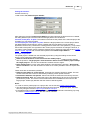
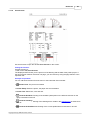
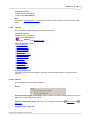
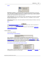
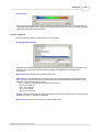
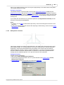
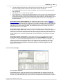
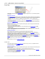
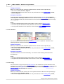
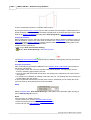
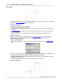
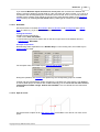
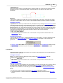
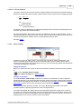
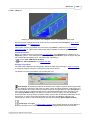
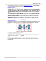
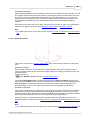
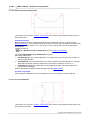
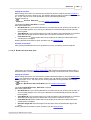
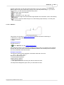
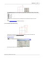
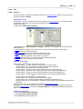
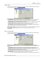
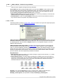
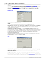
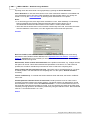
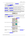
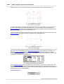
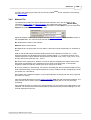
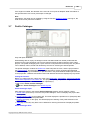
selected): The Window Read CAD-Contour appears (see picture), you can select the layer of
the desired roll and define the contour of the roll by setting the start (green) and end point (red)
of the contour (the intersection point of the edges and the center line in each case).
· ME10 or OneSpace Designer Drafting or PTC Creo Elements/Direct Drafting
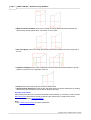
(Precondition: In Options Files Output to CAD, ME10 (MI) is selected): The file Rolle.mi is
read from the same path that is set for the output file. This file must contain the drawing of one
roll exactly. To get this file, select in ME10 the part that contains the roll (EDIT_PART) and
store the active part into a MI-file (STORE MI '.' DEL_OLD 'Rolle.mi'). The roll has to be drawn
with the same colors and line types that are used by PROFIL, when a drawing is created in
CAD.
· Others (Precondition: In Options Files Output to CAD, A11, DXF or IGES is selected): The
KTR or DXF file is read that is set in Options Files from CAD. This file must contain the
drawing of one roll exactly.
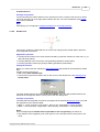
Insert Roll from File
This function is equivalent to Insert Roll from CAD, but the roll is not taken from a fixed source.
Instead of it, a file selection window opens and any DXF or KTR file can be selected as import file.
Copy Roll to Clipboard
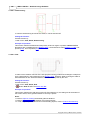
copies the selected roll from the database to the clipboard. From the clipboard, the roll can be
inserted into the current project by using the function Roll Insert.
Drawing -> CAD
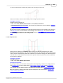
transfers the drawing of the selected roll directly to the CAD-system. This function uses the same
settings as the function Drawing -> CAD in the main window.
3.8.2
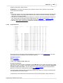
Roll Corner Table
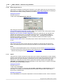
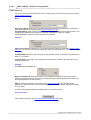
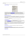
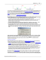
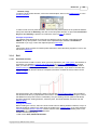
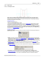
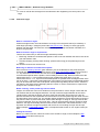
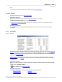
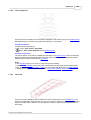
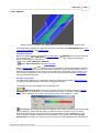
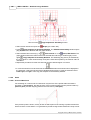
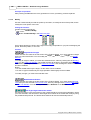
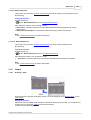
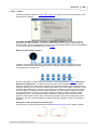
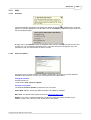
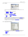
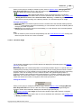
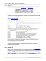
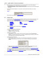
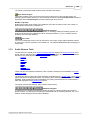
The left area in the middle of the Roll Stock Management Window displays the Roll Corner Points
of the roll, which is selected in the Roll Table Window at the bottom. Each line of the table displays
the data of one roll corner point. These are the corner point number and the data from the table of
the Roll Tool Window:
Width
Radius
Diameter
Angle
These data are automatically transferred, when a roll is inserted into the database or when a roll is
taken from the database.
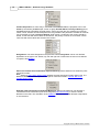
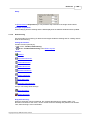
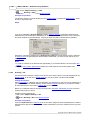
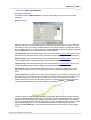
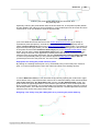
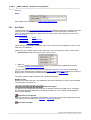
The belonging projects of the selected roll are displayed in the Project Table. Use a Filter to
Copyright 2015 by UBECO GmbH, Iserlohn