1
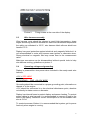
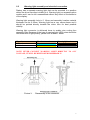
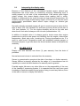
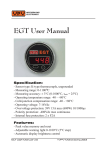
LAMBDA 2
USER MANUAL
©2012 VPV-Motorracing Electronics
TABLE OF CONTENTS
TABLE OF CONTENTS .........................................................................................................................2
1 TECHNICAL DETAILS..................................................................................................................3
1.1
General ...................................................................................................................................3
1.2
Technical specification ..........................................................................................................4
2 ASSEMBLY.....................................................................................................................................4
2.1
Sensor assembly .....................................................................................................................4
2.2
Display assembly....................................................................................................................5
2.3
Wire harness assembly..........................................................................................................6
2.4
Operating voltage and grounding .........................................................................................6
2.5
Warning light assembly and electrical connection ..............................................................7
3 OPERATION ...................................................................................................................................8
3.1
General ...................................................................................................................................8
3.2
Warning light adjustment......................................................................................................8
3.3
Interpreting the display value................................................................................................9
4. WARRANTY ...................................................................................................................................9
2
1
1.1
TECHNICAL DETAILS
General
VPV-Motorracing Electronics LAMBDA 2 is a single channel narrowband
air-fuel-ratio gauge with Bosch 4-wire zirconium-type lambda sensor.
Display is made using 16 superbright 5mm LEDs (colors red, red-orange,
yellow-orange, amber, yellow and green) with automatic brightness
control. Additional adjustable warning light included.
Contents of the gauge set:
-1 pc Display (1)
-1 pc Bosch 0 258 005 730 or 733 lambda sensor (2)
-1 pc Lambda mounting kit (3), (type may be various)
-1 pc Ready-made wire harness (4)
-1 pc Warning-LED (5) (available bezel colors: black, silver and gold)
-1 pc 2-pole connector body for warning-LED (6)
-10 pcs Cable tie (7)
-1 pc User Manual (not in picture)
Picture 1.
Contents of the gauge set
3
1.2
Technical specification
SENSOR:
Manufacturer:
Bosch-type:
Part number:
Type:
Material:
Wire count:
BOSCH-USA
LSH-25C or similar
0 258 005 730 or 733
Narrow-band
Zirconium
4
DISPLAY:
Measurement range (lambda-value):
Current consumption (display):
Current consumption (sensor heating):
Operating voltage:
Overvoltage protection:
Polarity protection:
Operational temperature:
Material of the enclosure:
Material of the front plate:
Dimensions (width x height x depth):
2
2.1
0.75 – 1.20
200mA max
1-4 A
8.3-16V DC
24V 600W 10/1000μs
500V continuous
-40°C-+70°C
ABS
1mm polycarbonate
130 x 65 x 25 mm
ASSEMBLY
Sensor assembly
Suitable assembly location for the sensor is in the front of exhaust system.
Sensor can normally handle 400-800°C exhaust temperature and
assembly should be made this in mind.
Lifetime of the sensor is strongly affected by some abnormal situations
and these must be taken into account when assembling sensor.
- Hot sensor is easily broken if it is exposed to condensing water
droplets. ’Clock 10:00-2:00’ is the best assembly location to avoid
this.
- Antilag systems or any other situation that causes fire in the
exhaust system are harmful for the lambda sensors. In these
situations it is recommended to assemble sensor further away from
engine. Sensor positioning towards the end of the exhaust system
can also help to prevent heat shocks to the sensor.
- Sensor outer shell and wires should be protected from the flying
stones or any other strong mechanical threat.
- Sensor wires should be protected from the exhaust temperatures,
200°C max allowed.
4
In naturally aspirated engine the optimal sensor position is dependent on
the type and dimensions of the exhaust manifold. Natural place for the
sensor is the nearest position from the engine where the exhaust gases
from all cylinders are thoroughly mixed. This location assures that the
measurement value is the mean of the all cylinders. Example: 4-2-1
manifold equipped engine; best sensor position is 100-200mm from 2-to-1
transition toward the end of the exhaust system.
In turbocharged engine the best location of the sensor is after the
turbocharger. The exhaust gas pressure affects lambda sensor output
voltage so the assembly before turbocharger is not allowed. NOTE! Antilag
system may have strong effect on sensor lifetime, please look at the
warnings and info earlier in this chapter.
When assembling lambda sensors to motorcycles an additional care
should be taken into account. Especially on 1-cylinder engine there are a
strong exhaust flow pulsations. Strong pulses may cause the air to be
sucked inside the exhaust system and this may cause static or pulsating
error on measurement. Assembling sensor very near the engine exhaust
port can minimize problem.
When using lambda sensor together with small diameter exhaust pipe it
may cause substantial flow restriction. This can be avoided by assembling
sensor with a longer weld bung. This may cause a slightly slower reaction
time but it doesn’t cause any static error.
When assembling sensor the threads of the sensor should be lubricated
with suitable high-temperature thread protecting paste. Without this paste
the thread may be seized within a very short time.
2.2
Display assembly
Natural assembly location for the display is inside the vehicle, normally on
the instrument panel. Display is waterproof only on the front side so the
assembly to wet location is not recommended.
Fixing can be made using the M4 sized screws attached at the backside of
the display unit. NOTE! Maximum depth screws can be inserted inside the
enclosure is 7mm measured from the outer surface of the display back
panel. Fixing can also be made using two-sided adhesive tape. If
additional holes are needed for fixing, display should be disassembled
before this to avoid any failures to the internal electronics.
NOTE! Inside the display there are M4 sized riveted nuts for the fixing
screws. If too much force is used for the disassembly of the M4 screws
these nuts may become loose. If this happens the usage of the display is
not allowed before loose nuts are removed or re-assembled. These loose
nuts may cause permanent electrical failures to the display.
5
Picture 2.
2.3
Fixing screws at the rear side of the display
Wire harness assembly
Wire harness route should be chosen to avoid high temperature, sharp
edges and strong electrical disturbance. Maximum continuous temperature
the cable can withstand is 125°C, wire harness black silicone shield can
handle 175°C.
Display has good protection against electrical and magnetic fields but it is
not recommended to route wire harness near ignition or alternator wires.
Strong electrical or magnetic field may cause error to the measurement
value.
Male-type connectors can be disassembled without special tools to help
wire harness routing, guidelines on picture 3.
2.4
Operating voltage and grounding
Display is powered thru two power wires included in the ready-made wire
harness:
+12V = RED WIRE
GROUNDING, -, GND = BLACK WIRE
Grounding should be connected to a proper grounding point, alternative on
chassis or in the engine.
+12V should be connected to a low electrical disturbance point, absolute
not directly to starter motor or alternator.
Display has internal fuses to protect display and sensor heating. To protect
power cables in wire harness it is recommended to connect a fuse to the
feed of the display. Maximum current consumption is 4A and suitable fuse
size is 5-10A
To maximize sensor lifetime it is recommended that system get its power
feed only when engine is running.
6
2.5
Warning light assembly and electrical connection
Display has a separate warning light that can be mounted to a position
where the driver has direct visibility to it. Warning light is a separate option
module and it can be left unassembled without any effect on the behavior
of the display.
Warning light assembly hole is ∅ 16mm and assembly location material
thickness can be 2-10mm. Warning light has a very narrow beam and it
should be pointed directly towards the driver face for best possible
visibility.
Warning light connector is delivered loose to enable wire routing thru
assembly hole. Because of the type of warning light (LED) wires should be
connected with a right polarity, please look at table 1 below.
Signal
+ / Anode
- / Katode
Table 1
Wire harness wire
Blue
Yellow
Warning light wire
Black
Grey
Warning light connection
NOTE! NEVER CONNECT WARNING LIGHT DIRECTLY TO +12V
VOLTAGE, IT WILL BE DESTROYED IMMEDIADLY!
Picture 3.
Disassembly of the connector
7
3
3.1
OPERATION
General
Display is ready to use, no calibration needed before use.
3.2
Warning light adjustment
Warning light level adjustment trimmer can be found on the backside of
the display. Adjustment is easiest made using flat screwdriver, size 3x
0,8mm max. Small Pozidriv or Phillips-type screwdriver is also suitable.
When adjustment is at the most counterclockwise (CCW) position the
warning light is OFF. Turned from this position to clockwise (CW) the
warning level will change from lambda value 1.2 towards lambda value
0.8, in most clockwise (CW) position lambda-value warning level is 0.80.
Warning light adjustment is linearly dependent on sensor voltage, because
of lambda sensor output non-linear behavior the adjustment is not linear in
lambda value. Please look pictures 4 and 5.
Picture 4.
Sensor output voltage as a function of temperature
Picture 5.
Warning light adjustment screw and approximate values
8
3.3
Interpreting the display value
Because of the features of the narrowband lambda sensor exhaust gas
temperature has some effect on measuring accuracy. Measuring error is
mostly present on rich side of the measurement. Cold sensor gives higher
output voltage; this means display shows richer reading than in reality.
Display is constructed to be most accurate on high exhaust temperature; the
situation normal in highly loaded racing engine. In Picture 4 you can see some
approximately presentation about sensor output voltage vs. exhaust gas
temperature.
Normally naturally aspirated engine will give its maximum power when air-fuel
ratio is about 10% rich (lambda 0.9) and best economy when air-fuel ratio is
10% lean (lambda 1.1). For the engine durability we are on the safe side
when the air-fuel ratio is always on the rich side (lambda below 1.0).
In addition to lambda value it is always good to check some other engine
parameters to get the most power and reliability from the engine; exhaust gas
temperature, spark plug color, knocking etc. During dynosessions etc. it is
good to make some comparative study with wideband lambda gauges or
exhaust analyzers to get idea about the actual lambda values in this particular
assembly.
4.
WARRANTY
Display and wire harness has three (3) year warranty from the date of
purchase.
Normal wear and misuse is excluded from the warranty.
Sensor is guaranteed to operate at the date of purchase, no further warranty.
Sensor lifetime is strongly affected by the usage of it; manufacturer has no
capability to control this and therefore no warranty can be granted.
Possible engine failures or any other fails are on the responsibility of the user
of the Lambda 2 measuring system. It is expected that the user have good
knowledge of lambda measuring and engine tuning to avoid any failures, even
in the case of sensor or display unit failures.
9