1
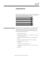
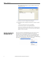
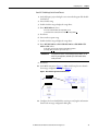
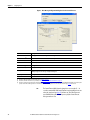
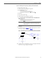
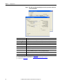
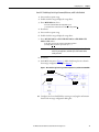
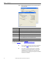
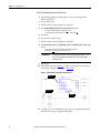
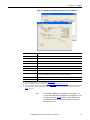
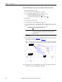
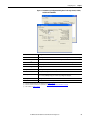
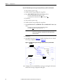
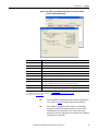
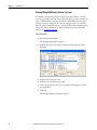
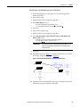
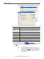
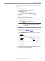
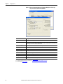
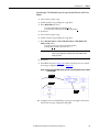
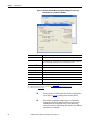
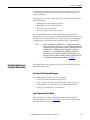
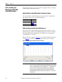
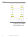
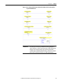
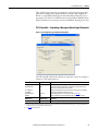
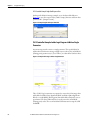
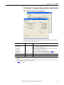
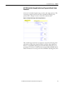
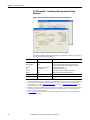
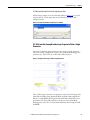
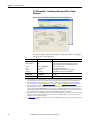
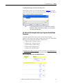
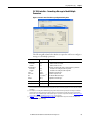
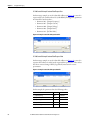
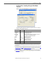
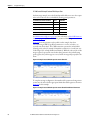
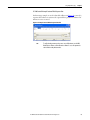
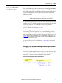
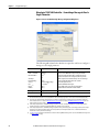
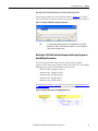
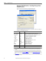
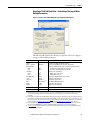
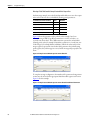
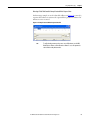
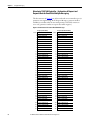
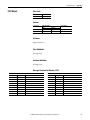
Configuring the I/O
Chapter 1
Create MicroLogix 1100/1400 Ladder Logic for the Control Timeout
1. In the RSLogix 500 project dialog box treeview under Program Files
double-click LAD 2.
2. Insert a ladder rung.
3. Double-click the rung to display the rung editor.
4. Enter MSG MGxx:n, where:
xx is an unused data file number (for example, MG10:n), and
n is an unused element of the data file chosen for xx (for example, MG10:0)
5. Press Enter.
6. Insert another separate rung.
7. Double-click the rung to display the rung editor.
8. Enter BST XIC MGxx:n/DN NXB XIC MGxx:n/ER BND OTU
MGxx:n/EN, where:
xx and n must correspond to the assigned data file number and element
(for example, MG10:0) for the message created in steps 2…5.
IMPORTANT
The information must be entered with appropriate numbers for ‘xx’
and ‘n’ for your application, and with spaces and forward slashes
exactly as shown.
9. Press Enter.
10. In the MSG instruction (Figure 16), double-click Setup Screen to launch
the message configuration dialog box (Figure 17).
Figure 16 - MicroLogix 1100/1400 Ladder Logic for the Control Timeout
Steps 2…5
Steps 6…9
Step 10
11. Configure the General tab fields by entering or verifying the information
shown in the message configuration dialog box.
Rockwell Automation Publication 750COM-AT001A-EN-P - August 2012
31