1
December 25, 2007
Corrections to
SDC45A/46A Digital Indicating Controller
User's Manual for Installation and Configuration
(No. CP-SP-1218E, 1st edition dated Nov., 2007)
Errors were found in the table in Chapter 10, "List of Communication Data," in
the digits shown in the "EEPROM address, Hexadecimal" column.
Please apply the following corrections:
Incorrect
Correct
9✽✽✽
A✽✽✽
B✽✽✽
C✽✽✽
5✽✽✽
6✽✽✽
7✽✽✽
8✽✽✽
"✽✽✽" indicates 3 alphanumeric characters.
For example, in the table on page 10-1, in the first row of data, the EEPROM
address is given as 9000, but 5000 is correct. All addresses in the EEPROM
address column should be corrected.
If the wrong address is used in a WRITE command, and the command is sent by
communications, writing is done only in RAM. Therefore, after the power is
turned off, the data stored in EEPROM will be restored.
Be sure not to use an incorrect address. If an incorrect address is used in
communications, the wrong READ/WRITE operation will be carried out. A
WRITE command using data that is outside of the proper range may be
dangerous, because it could cause a controller operation error.
These errors will be corrected in the 2nd edition of the user's manual.
No. CP-SP-1218E
SDC45A/46A
Digital Indicating Controller
User's Manual
for
Installation and Configuration
Thank you for purchasing the SDC45A/
46A Digital Indicating Controller.
This manual contains information for
ensuring the correct use of the SDC45A/
46A. It also provides necessary information for installation, maintenance, and
troubleshooting.
This manual should be read by those
who design and maintain equipment
that uses the SDC45A/46A. Be sure to
keep this manual nearby for handy reference.
RESTRICTIONS ON USE
This product has been designed, developed and manufactured for general-purpose
application in machinery and equipment.
Accordingly, when used in applications outlined below, special care should be taken to
implement a fail-safe and/or redundant design concept as well as a periodic
maintenance program.
• Safety devices for plant worker protection
• Start/stop control devices for transportation and material handling machines
• Aeronautical/aerospace machines
• Control devices for nuclear reactors
Never use this product in applications where human safety may be put at risk.
NOTICE
Be sure that the user receives this manual before the product is used.
Copying or duplicating this user’s manual in part or in whole is forbidden. The information and specifications in this manual are subject to
change without notice.
Considerable effort has been made to ensure that this manual is free
from inaccuracies and omissions. If you should find an error or omission, please contact Yamatake Corporation.
In no event is Yamatake Corporation liable to anyone for any indirect,
special or consequential damages as a result of using this product.
©2007 Yamatake Corporation ALL RIGHTS RESERVED
SAFETY REQUIREMENTS
To reduce risk of electric shock which could cause personal injury, follow all safety
notices in this documentation.
This symbol warns the user of a potential shock hazard where hazardous live voltages
may be accessible.
•
•
•
•
•
If the equipment is used in a manner not specified by the manufacturer, the protection
provided by the equipment must be impaired.
Do not replace any component (or part) not explicitly specified as replaceable by your
supplier.
All wiring must be in accordance with local norms and carried out by authorized and
experienced personnel.
A switch in the main supply is required near the equipment.
Main power supply wiring requires a (T) 1.0 A, 250 V fuse(s) (IEC 127).
EQUIPMENT RATINGS
Supply voltages:
100 to 240 Vac (operating power supply voltage 85 to 264Vac)
Frequency:
50/60 Hz
Power consumption:
30 VA maximum (SDC45A), 40 VA maximum (SDC46A)
EQUIPMENT CONDITIONS
Do not operate the instrument in the presence of flammable liquids or vapors.
Operation of any electrical instrument in such an environment constitutes a safety hazard.
Temperature:
0 to 50 ˚C
Humidity:
10 to 90 %RH (non-condensing)
Vibration:
2 m/s2 (10 to 60 Hz)
Over-voltage category:
Category II (IEC60364-4-443, EN60664-1)
Pollution degree:
2
EQUIPMENT INSTALLATION
The controller must be mounted into a panel to limit operator access to the rear terminal.
Specifications of common mode voltage: The common mode voltages of all I/O except for main
supply and relay outputs are less than 33 V r.m.s. max., 46.7 V peak max., and 70 Vdc max.
STANDARDS COMPLIANCE
EN61010-1, EN61326
i
SAFETY PRECAUTIONS
■ About Icons
The safety precautions described in this manual are indicated by various icons.
Please be sure you read and understand the icons and their meanings described
below before reading the rest of the manual.
Safety precautions are intended to ensure the safe and correct use of this product, to prevent injury to the operator and others, and to prevent damage to property. Be sure to observe these safety precautions.
WARNING
Warnings are indicated when mishandling this
product might result in death or serious injury.
CAUTION
Cautions are indicated when mishandling this
product might result in minor injury to the user, or
only physical damage to the product.
■ Examples
Use caution when handling the product.
The indicated action is prohibited.
Be sure to follow the indicated instructions.
ii
WARNING
Before connecting the SDC45A/46A to the measurement target or to
external control circuits, make sure that the frame ground (FG) terminal
is properly grounded with an earth ground of less than 100 Ω.
Failure to so might cause an electric shock or fire.
Before wiring, removing or mounting the SDC45A/46A, be sure to turn
the power OFF.
Failure to do so might cause electric shock or device failure.
Incorrect wiring of the SDC45A/46A can damage the SDC45A/46A and
lead to other hazards. Check that the SDC45A/46A has been correctly
wired before turning the power ON.
Do not touch electrically charged parts such as the power terminals.
Doing so might cause electric shock.
Do not disassemble the SDC45A/46A.
Doing so might cause electric shock or device failure.
CAUTION
Use the SDC45A/46A within the operating ranges recommended in the
specifications (temperature, humidity, voltage, vibration, shock,
mounting direction, atmosphere, etc.).
Failure to do so might cause fire or device failure.
Do not block ventilation holes.
Doing so might cause fire or device failure.
Wire the SDC45A/46A properly using the specified types of wire and
following recognized installation methods.
Failure to do so might cause electric shock, fire or device failure.
Do not allow wire clippings, chips or water to enter the controller case.
They might cause fire or device failure.
Firmly tighten the terminal screws to the torque listed in the
specifications. Insufficient tightening of terminal screws might cause
electric shock or fire.
Do not use unused terminals on the SDC45A/46A as relay terminals.
Doing so might cause electric shock, fire or device failure.
We recommend attaching the terminal cover (sold separately) after
wiring the SDC45A/46A.
Failure to do so might cause electric shock.
iii
CAUTION
Use the relays within the recommended service life.
Failure to do so might cause fire or device failure.
Use Yamatake Corporation's SURGENON if there is a risk of power
surges caused by lightning.
Otherwise, fire or device failure could result.
Do not operate the keys with a mechanical pencil or other sharp-tipped
object.
Doing so might cause device failure.
After the power has been turned ON, the SDC45A/46A does not operate
for 2 to 60 s according to the settings.
Therefore, great care should be taken if the relay output from the
controller is used as an interlock signal.
iv
The Role of This Manual
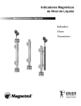
A total of 4 different manuals are available for the SDC45A/46A. Read them as necessary for your specific requirements. If a manual you require is not available, contact Yamatake Corporation or its dealer.
C P-U
U
3E
M-012
nual
ser's Ma
G
WARNIN
N
CAUTIO
WARN
CAU TI
ING
ON
SDC45A/46A Digital Indicating Controller Installation Instructions
Manual No. CP-UM-5445E
This manual is supplied with the SDC45A/46A. Personnel in charge of design
and/or manufacture of a system using the SDC45A/46A must thoroughly read
this manual. This manual describes the safety precautions, installation, wiring,
primary specifications, and transitions of key operations and displays. For
further information about operation, refer to another manual, Installation and
Configuration.
SDC45A/46A Digital Indicating Controller User's Manual for Displays
and Settings
Manual No. CP-SP-1265E
The manual is a reference document necessary to set or change data. The
manual lists up the displays, setup items, setting ranges, and initial values.
SDC45A/46A Digital Indicating Controller User's Manual for Installation
and Configuration
Manual No. CP-SP-1218E
This manual. Personnel in charge of design, manufacture, operation, and/or
maintenance of a system using SDC45A/46A must thoroughly read this
manual. This manual also describes the installation, wiring, connections for
communication, all functions and settings of the SDC45A/46A, operating
procedures, troubleshooting, and detailed specifications.
SLP-C45 Smart Loader Package for the SDC45A/46A Digital Indicating
Controller
Manual No. CP-UM-5458E
This manual is supplied with the SLP-C45 Smart Loader Package. The manual describes the software used to make various settings for the
SDC45A/46A using a personal computer. Personnel in charge of design or
setting of a system using SDC45A/46A must thoroughly read this manual.
The manual describes installation of the software into a personal computer,
operation of the personal computer, various functions, and setup procedures.
v
Organization of This User's Manual
This manual is organized as follows:
Flowchart of key operations and displays
This section summarizes the flowchart of key operations and displays of the
SDC45A/46A in the diagram so as to describe them.
Chapter 1. OVERVIEW
This chapter describes the overview, features, model selection guide, and part
names and functions of the SDC45A/46A.
Chapter 2. INSTALLATION
This chapter describes the environmental conditions and installation procedures
when installing the SDC45A/46A.
Chapter 3. WIRING
This chapter describes the wiring procedures, wiring precautions, and connection
examples.
Chapter 4. FUNCTIONS NECESSARY FOR CONTROL
This chapter describes the functions absolutely necessary to operate the control of
the SDC45A/46A.
Chapter 5. OPERATION AND GENERAL FUNCTIONS
This chapter describes how to set the functions, which are normally used for the
SDC45A/46A.
Chapter 6. FUNCTIONS OFTEN USED FOR OPERATIONS OTHER THAN CONTROL
This chapter describes how to set the functions, which are used for operations other
than the control actions of the SDC45A/46A.
Chapter 7. FUNCTIONS USED AS REQUIRED
This chapter describes how to set the functions necessary for convenient operations
of the SDC45A/46A.
Chapter 8. LIST OF SETTINGS
Refer to: "SDC45A/46A Digital Indicating Controller for Displays and
Settings (CP-SP-1265E)".
Chapter 9. CPL COMMUNICATION FUNCTION
This chapter describes how to communicate the SDC45A/46A with a host unit,
such as a personal computer or PLC through Yamatake's standard CPL communication using RS-485.
Chapter 10. LIST OF COMMUNICATION DATA
This chapter shows the list of communication data inside the memory of the
SDC45A/46A.
vi
Chapter 11. TROUBLESHOOTING
This chapter describes the troubleshooting of the SDC45A/46A.
Chapter 12. MAINTENANCE, INSPECTION, AND DISPOSAL
This chapter describes how to carry out the maintenance and inspection of the
SDC45A/46A and how to dispose of the SDC45A/46A.
Chapter 13. SPECIFICATIONS
This chapter describes the general specifications, performance specifications,
external dimensions, and optional parts of the SDC45A/46A.
Appendixes
These appendixes describe the function block diagrams, standard bit codes, standard numerical bit codes, and using characters and terms used in descriptions of
this manual.
vii
Contents
SAFETY REQUIREMENTS
SAFETY PRECAUTIONS
The Role of This Manual
Organization of This User's Manual
Conventions Used in This Manual
Flowchart of key operations and displays
Chapter 1.
OVERVIEW
1-1 Overview and Features • • • • • • • • • • • • • • • • • • • • • • • • • • • • • • • • • • • • • • • • • • • • • • • • • • • • 1-1
■ Overview • • • • • • • • • • • • • • • • • • • • • • • • • • • • • • • • • • • • • • • • • • • • • • • • • • • • • • • • • • • • • • • 1-1
■ Features • • • • • • • • • • • • • • • • • • • • • • • • • • • • • • • • • • • • • • • • • • • • • • • • • • • • • • • • • • • • • • • 1-1
1-2 Model Selection Table • • • • • • • • • • • • • • • • • • • • • • • • • • • • • • • • • • • • • • • • • • • • • • • • • • • • • 1-3
■ SDC45A (with 14-digit model No.) • • • • • • • • • • • • • • • • • • • • • • • • • • • • • • • • • • • • • • 1-3
■ SDC46A (with 14-digit model No.) • • • • • • • • • • • • • • • • • • • • • • • • • • • • • • • • • • • • • • 1-4
■ SDC45A/46A (with 7-digit model No.) • • • • • • • • • • • • • • • • • • • • • • • • • • • • • • • • • • 1-5
■ Accessories and optional parts • • • • • • • • • • • • • • • • • • • • • • • • • • • • • • • • • • • • • • • • 1-5
1-3 Names and Functions of Parts • • • • • • • • • • • • • • • • • • • • • • • • • • • • • • • • • • • • • • • • • • • • • 1-6
■ Front panel • • • • • • • • • • • • • • • • • • • • • • • • • • • • • • • • • • • • • • • • • • • • • • • • • • • • • • • • • • • • • 1-6
■ Rear panel • • • • • • • • • • • • • • • • • • • • • • • • • • • • • • • • • • • • • • • • • • • • • • • • • • • • • • • • • • • • • 1-7
1-4 Operation Modes • • • • • • • • • • • • • • • • • • • • • • • • • • • • • • • • • • • • • • • • • • • • • • • • • • • • • • • • • • 1-8
Chapter 2.
INSTALLATION
■
■
■
■
Chapter 3.
Location • • • • • • • • • • • • • • • • • • • • • • • • • • • • • • • • • • • • • • • • • • • • • • • • • • • • • • • • • • • • • • • 2-1
External dimensions • • • • • • • • • • • • • • • • • • • • • • • • • • • • • • • • • • • • • • • • • • • • • • • • • • • 2-1
Panel cutout dimensions• • • • • • • • • • • • • • • • • • • • • • • • • • • • • • • • • • • • • • • • • • • • • • • 2-2
Mounting procedure • • • • • • • • • • • • • • • • • • • • • • • • • • • • • • • • • • • • • • • • • • • • • • • • • • • 2-3
WIRING
3-1 Wiring Precautions • • • • • • • • • • • • • • • • • • • • • • • • • • • • • • • • • • • • • • • • • • • • • • • • • • • • • • • • 3-1
■ Wiring precautions • • • • • • • • • • • • • • • • • • • • • • • • • • • • • • • • • • • • • • • • • • • • • • • • • • • • • 3-2
3-2 Recommended Cables • • • • • • • • • • • • • • • • • • • • • • • • • • • • • • • • • • • • • • • • • • • • • • • • • • • • • 3-3
3-3 Terminal Connections • • • • • • • • • • • • • • • • • • • • • • • • • • • • • • • • • • • • • • • • • • • • • • • • • • • • • 3-4
3-4 Terminal Wiring Diagram • • • • • • • • • • • • • • • • • • • • • • • • • • • • • • • • • • • • • • • • • • • • • • • • • • 3-5
■ SDC45A terminals• • • • • • • • • • • • • • • • • • • • • • • • • • • • • • • • • • • • • • • • • • • • • • • • • • • • • • 3-5
■ SDC46A terminals• • • • • • • • • • • • • • • • • • • • • • • • • • • • • • • • • • • • • • • • • • • • • • • • • • • • • • 3-6
3-5 Power Supply Connections and Grounding • • • • • • • • • • • • • • • • • • • • • • • • • • • • • • • 3-7
■ Power supply connections • • • • • • • • • • • • • • • • • • • • • • • • • • • • • • • • • • • • • • • • • • • • • 3-7
■ Grounding • • • • • • • • • • • • • • • • • • • • • • • • • • • • • • • • • • • • • • • • • • • • • • • • • • • • • • • • • • • • • 3-7
3-6 PV Input (PV) Connections • • • • • • • • • • • • • • • • • • • • • • • • • • • • • • • • • • • • • • • • • • • • • • • • 3-8
■ PV input 1 (PV1) connection • • • • • • • • • • • • • • • • • • • • • • • • • • • • • • • • • • • • • • • • • • • 3-8
viii
■ PV input 2 (PV2) connection • • • • • • • • • • • • • • • • • • • • • • • • • • • • • • • • • • • • • • • • • • • 3-8
3-7 Output (OUT) Connections • • • • • • • • • • • • • • • • • • • • • • • • • • • • • • • • • • • • • • • • • • • • • • • • 3-9
■ Relay output • • • • • • • • • • • • • • • • • • • • • • • • • • • • • • • • • • • • • • • • • • • • • • • • • • • • • • • • • • • 3-9
■ Current output, continuous voltage output, voltage pulse output,
and power supply for transmitter • • • • • • • • • • • • • • • • • • • • • • • • • • • • • • • • • • • • • • 3-9
■ Connection with solid state relay (SSR) • • • • • • • • • • • • • • • • • • • • • • • • • • • • • • 3-10
■ Connection with transmitter (4 to 20 mAdc output) • • • • • • • • • • • • • • • • • • • 3-11
3-8 Digital Input (DI) Connections • • • • • • • • • • • • • • • • • • • • • • • • • • • • • • • • • • • • • • • • • • • • 3-12
3-9 Digital Output (DO) Connections • • • • • • • • • • • • • • • • • • • • • • • • • • • • • • • • • • • • • • • • • 3-13
3-10 RS-485 Communication Connections • • • • • • • • • • • • • • • • • • • • • • • • • • • • • • • • • • • • 3-14
3-11 Noise Generation Sources and Noise Suppression • • • • • • • • • • • • • • • • • • • • • • 3-17
3-12 I/O Isolation • • • • • • • • • • • • • • • • • • • • • • • • • • • • • • • • • • • • • • • • • • • • • • • • • • • • • • • • • • • • • • • 3-18
Flowcharts for Major Settings
1.
2.
Chapter 4.
Setting of PARA bank • • • • • • • • • • • • • • • • • • • • • • • • • • • • • • • • • • • • • • • • • • • • • • • • • • • • • A-2
Setting of SP/EV bank • • • • • • • • • • • • • • • • • • • • • • • • • • • • • • • • • • • • • • • • • • • • • • • • • • • • • A-4
FUNCTIONS NECESSARY FOR CONTROL
4-1 How to Set the Loop Type (2-input Model) • • • • • • • • • • • • • • • • • • • • • • • • • • • • • • • • • 4-1
■ Bank and settings • • • • • • • • • • • • • • • • • • • • • • • • • • • • • • • • • • • • • • • • • • • • • • • • • • • • • • 4-1
■ Setting procedures• • • • • • • • • • • • • • • • • • • • • • • • • • • • • • • • • • • • • • • • • • • • • • • • • • • • • 4-1
4-2 How to Set the Input Type • • • • • • • • • • • • • • • • • • • • • • • • • • • • • • • • • • • • • • • • • • • • • • • • • 4-2
■ Bank and settings • • • • • • • • • • • • • • • • • • • • • • • • • • • • • • • • • • • • • • • • • • • • • • • • • • • • • • 4-2
■ Description of display • • • • • • • • • • • • • • • • • • • • • • • • • • • • • • • • • • • • • • • • • • • • • • • • • • 4-2
■ Setting procedures• • • • • • • • • • • • • • • • • • • • • • • • • • • • • • • • • • • • • • • • • • • • • • • • • • • • • 4-2
■ Input types • • • • • • • • • • • • • • • • • • • • • • • • • • • • • • • • • • • • • • • • • • • • • • • • • • • • • • • • • • • • • 4-3
4-3 How to Set Range-Related Items • • • • • • • • • • • • • • • • • • • • • • • • • • • • • • • • • • • • • • • • • • • 4-4
■ Bank and settings • • • • • • • • • • • • • • • • • • • • • • • • • • • • • • • • • • • • • • • • • • • • • • • • • • • • • • 4-4
■ Range setup • • • • • • • • • • • • • • • • • • • • • • • • • • • • • • • • • • • • • • • • • • • • • • • • • • • • • • • • • • • 4-4
■ Setting procedures• • • • • • • • • • • • • • • • • • • • • • • • • • • • • • • • • • • • • • • • • • • • • • • • • • • • • 4-4
4-4 How to Set the Loop Control Action • • • • • • • • • • • • • • • • • • • • • • • • • • • • • • • • • • • • • • • 4-9
■ Bank and settings • • • • • • • • • • • • • • • • • • • • • • • • • • • • • • • • • • • • • • • • • • • • • • • • • • • • 4-10
■ Setting procedures • • • • • • • • • • • • • • • • • • • • • • • • • • • • • • • • • • • • • • • • • • • • • • • • • • • 4-10
4-5 How to Set Outputs (continuous output and time proportional output) • • • • • 4-11
■ Output types, applications, and settings • • • • • • • • • • • • • • • • • • • • • • • • • • • • • 4-11
■ Bank and settings • • • • • • • • • • • • • • • • • • • • • • • • • • • • • • • • • • • • • • • • • • • • • • • • • • • • 4-11
■ Description of display • • • • • • • • • • • • • • • • • • • • • • • • • • • • • • • • • • • • • • • • • • • • • • • • 4-12
■ Setting procedures • • • • • • • • • • • • • • • • • • • • • • • • • • • • • • • • • • • • • • • • • • • • • • • • • • • 4-12
■ Continuous output setup • • • • • • • • • • • • • • • • • • • • • • • • • • • • • • • • • • • • • • • • • • • • • 4-13
■ Time proportional output setup • • • • • • • • • • • • • • • • • • • • • • • • • • • • • • • • • • • • • • • 4-14
■ ON/OFF output setup • • • • • • • • • • • • • • • • • • • • • • • • • • • • • • • • • • • • • • • • • • • • • • • • • 4-14
ix
Chapter 5.
OPERATION AND GENERAL FUNCTIONS
5-1 Operation Displays • • • • • • • • • • • • • • • • • • • • • • • • • • • • • • • • • • • • • • • • • • • • • • • • • • • • • • • • 5-1
■ 1-loop • • • • • • • • • • • • • • • • • • • • • • • • • • • • • • • • • • • • • • • • • • • • • • • • • • • • • • • • • • • • • • • • • • 5-1
■ 2-loop independent • • • • • • • • • • • • • • • • • • • • • • • • • • • • • • • • • • • • • • • • • • • • • • • • • • • • 5-1
■ 1-loop with RSP • • • • • • • • • • • • • • • • • • • • • • • • • • • • • • • • • • • • • • • • • • • • • • • • • • • • • • • • 5-2
■ Computer backup • • • • • • • • • • • • • • • • • • • • • • • • • • • • • • • • • • • • • • • • • • • • • • • • • • • • • • 5-2
■ Internal cascade • • • • • • • • • • • • • • • • • • • • • • • • • • • • • • • • • • • • • • • • • • • • • • • • • • • • • • • 5-3
■ Display status of mode indicator lamps • • • • • • • • • • • • • • • • • • • • • • • • • • • • • • • • 5-4
5-2 How to Change the SP • • • • • • • • • • • • • • • • • • • • • • • • • • • • • • • • • • • • • • • • • • • • • • • • • • • • • 5-5
■ Setting procedures• • • • • • • • • • • • • • • • • • • • • • • • • • • • • • • • • • • • • • • • • • • • • • • • • • • • • 5-5
5-3 How to Change the SP Group/Recipe Group• • • • • • • • • • • • • • • • • • • • • • • • • • • • • • • 5-6
■ Setting procedures• • • • • • • • • • • • • • • • • • • • • • • • • • • • • • • • • • • • • • • • • • • • • • • • • • • • • 5-6
5-4 How to Change the PID (auto tuning) • • • • • • • • • • • • • • • • • • • • • • • • • • • • • • • • • • • • • • 5-7
■ Starting procedures • • • • • • • • • • • • • • • • • • • • • • • • • • • • • • • • • • • • • • • • • • • • • • • • • • • • 5-7
■ Stopping procedures • • • • • • • • • • • • • • • • • • • • • • • • • • • • • • • • • • • • • • • • • • • • • • • • • • 5-7
■ Display while AT is running • • • • • • • • • • • • • • • • • • • • • • • • • • • • • • • • • • • • • • • • • • • • 5-7
5-5 How to Change the PID (manual) • • • • • • • • • • • • • • • • • • • • • • • • • • • • • • • • • • • • • • • • • • 5-8
■ Setting procedures• • • • • • • • • • • • • • • • • • • • • • • • • • • • • • • • • • • • • • • • • • • • • • • • • • • • • 5-8
5-6 How to Change the Event Action Point • • • • • • • • • • • • • • • • • • • • • • • • • • • • • • • • • • • • 5-9
■ Setting procedures (for multi-SP) • • • • • • • • • • • • • • • • • • • • • • • • • • • • • • • • • • • • • • 5-9
■ Setting procedures (for recipe) • • • • • • • • • • • • • • • • • • • • • • • • • • • • • • • • • • • • • • • 5-10
5-7 How to Start and Stop the Control Operation (RUN/READY)• • • • • • • • • • • • • • 5-11
■ Setting procedures • • • • • • • • • • • • • • • • • • • • • • • • • • • • • • • • • • • • • • • • • • • • • • • • • • • 5-11
5-8 How to Manually Output the MV (AUTO/MANUAL) • • • • • • • • • • • • • • • • • • • • • • • • 5-12
■ Setting procedures • • • • • • • • • • • • • • • • • • • • • • • • • • • • • • • • • • • • • • • • • • • • • • • • • • • 5-12
5-9 How to Change to the Remote SP (RSP/LSP) • • • • • • • • • • • • • • • • • • • • • • • • • • • • • 5-13
■ How to change to the remote (RSP)• • • • • • • • • • • • • • • • • • • • • • • • • • • • • • • • • • • 5-13
■ How to change to the local (LSP) • • • • • • • • • • • • • • • • • • • • • • • • • • • • • • • • • • • • • 5-13
5-10 How to Change the SP with Constant Ramp • • • • • • • • • • • • • • • • • • • • • • • • • • • • • • 5-14
■ Bank and settings • • • • • • • • • • • • • • • • • • • • • • • • • • • • • • • • • • • • • • • • • • • • • • • • • • • • 5-14
■ Setting procedures • • • • • • • • • • • • • • • • • • • • • • • • • • • • • • • • • • • • • • • • • • • • • • • • • • • 5-14
■ Conditions for ramp start • • • • • • • • • • • • • • • • • • • • • • • • • • • • • • • • • • • • • • • • • • • • • 5-15
■ Conditions for ramp start with PV used as start point • • • • • • • • • • • • • • • • 5-15
Chapter 6.
FUNCTIONS OFTEN USED FOR OPERATIONS OTHER THAN
CONTROL
6-1 How to Set the Priority • • • • • • • • • • • • • • • • • • • • • • • • • • • • • • • • • • • • • • • • • • • • • • • • • • • • • 6-1
■ Setting bank • • • • • • • • • • • • • • • • • • • • • • • • • • • • • • • • • • • • • • • • • • • • • • • • • • • • • • • • • • • 6-1
■ Example: Selection of SP group • • • • • • • • • • • • • • • • • • • • • • • • • • • • • • • • • • • • • • • 6-1
■ Functions whose priority can be set for each control loop • • • • • • • • • • • • 6-2
■ Functions whose priority can be set regardless of control loop • • • • • • • 6-2
6-2 How to Use Events• • • • • • • • • • • • • • • • • • • • • • • • • • • • • • • • • • • • • • • • • • • • • • • • • • • • • • • • • 6-3
■ Setting banks • • • • • • • • • • • • • • • • • • • • • • • • • • • • • • • • • • • • • • • • • • • • • • • • • • • • • • • • • • 6-3
■ Example: PV high limit alarm (on if an error occurs) • • • • • • • • • • • • • • • • • • • 6-3
x
6-3
6-4
6-5
6-6
Chapter 7.
■ Event operation type, polarity, hysteresis, main setting,
and sub-setting • • • • • • • • • • • • • • • • • • • • • • • • • • • • • • • • • • • • • • • • • • • • • • • • • • • • • • • • 6-5
■ Event standby and operation at READY • • • • • • • • • • • • • • • • • • • • • • • • • • • • • • • 6-8
■ Event decimal point • • • • • • • • • • • • • • • • • • • • • • • • • • • • • • • • • • • • • • • • • • • • • • • • • • • • 6-8
■ ON delay and OFF delay • • • • • • • • • • • • • • • • • • • • • • • • • • • • • • • • • • • • • • • • • • • • • • • 6-8
How to Use Internal Contact Input • • • • • • • • • • • • • • • • • • • • • • • • • • • • • • • • • • • • • • • • • 6-9
■ Setting banks • • • • • • • • • • • • • • • • • • • • • • • • • • • • • • • • • • • • • • • • • • • • • • • • • • • • • • • • • • 6-9
■ Example 1: RUN/READY change-over by internal contact input • • • • • • • 6-9
■ Example 2: SP group selection by internal contact input • • • • • • • • • • • • • 6-10
■ Operation type (i c-0 1)• • • • • • • • • • • • • • • • • • • • • • • • • • • • • • • • • • • • • • • • • • • • • • • • 6-11
■ Input type (i c-02) • • • • • • • • • • • • • • • • • • • • • • • • • • • • • • • • • • • • • • • • • • • • • • • • • • • • 6-12
■ Loop/channel definition (i c-03) • • • • • • • • • • • • • • • • • • • • • • • • • • • • • • • • • • • • • • 6-12
■ Weighting (i c-04) • • • • • • • • • • • • • • • • • • • • • • • • • • • • • • • • • • • • • • • • • • • • • • • • • • • • 6-12
How to Use Digital Output • • • • • • • • • • • • • • • • • • • • • • • • • • • • • • • • • • • • • • • • • • • • • • • • 6-13
■ Setting banks • • • • • • • • • • • • • • • • • • • • • • • • • • • • • • • • • • • • • • • • • • • • • • • • • • • • • • • • • 6-13
■ Example: DO turns ON if PV1 high limit error occurs • • • • • • • • • • • • • • • • • 6-13
■ Output type (doc.0 1) • • • • • • • • • • • • • • • • • • • • • • • • • • • • • • • • • • • • • • • • • • • • • • • • • • 6-14
■ Latch (doc.02) • • • • • • • • • • • • • • • • • • • • • • • • • • • • • • • • • • • • • • • • • • • • • • • • • • • • • • • • 6-14
How to Use the Multi-SP • • • • • • • • • • • • • • • • • • • • • • • • • • • • • • • • • • • • • • • • • • • • • • • • • • 6-15
■ Setting banks • • • • • • • • • • • • • • • • • • • • • • • • • • • • • • • • • • • • • • • • • • • • • • • • • • • • • • • • • 6-15
■ Features • • • • • • • • • • • • • • • • • • • • • • • • • • • • • • • • • • • • • • • • • • • • • • • • • • • • • • • • • • • • • • 6-15
■ Example: Multi-SP is used with two LSP groups• • • • • • • • • • • • • • • • • • • • • • 6-15
How to Use Recipes • • • • • • • • • • • • • • • • • • • • • • • • • • • • • • • • • • • • • • • • • • • • • • • • • • • • • • 6-17
■ Setting banks • • • • • • • • • • • • • • • • • • • • • • • • • • • • • • • • • • • • • • • • • • • • • • • • • • • • • • • • • 6-17
■ Features • • • • • • • • • • • • • • • • • • • • • • • • • • • • • • • • • • • • • • • • • • • • • • • • • • • • • • • • • • • • • • 6-17
■ Example: Recipe of the LSP 2 group is used • • • • • • • • • • • • • • • • • • • • • • • • • 6-17
FUNCTIONS USED AS REQUIRED
7-1 Internal Cascade Function • • • • • • • • • • • • • • • • • • • • • • • • • • • • • • • • • • • • • • • • • • • • • • • • • 7-1
■ Setting banks • • • • • • • • • • • • • • • • • • • • • • • • • • • • • • • • • • • • • • • • • • • • • • • • • • • • • • • • • • 7-1
■ Example: The MV on the slave side is output from output 3
by internal cascade control • • • • • • • • • • • • • • • • • • • • • • • • • • • • • • • • • • • • • • • • • • • • 7-1
7-2 Computer Backup • • • • • • • • • • • • • • • • • • • • • • • • • • • • • • • • • • • • • • • • • • • • • • • • • • • • • • • • • 7-4
■ Setting banks • • • • • • • • • • • • • • • • • • • • • • • • • • • • • • • • • • • • • • • • • • • • • • • • • • • • • • • • • • 7-4
■ Example • • • • • • • • • • • • • • • • • • • • • • • • • • • • • • • • • • • • • • • • • • • • • • • • • • • • • • • • • • • • • • • • 7-4
7-3 RSP Multi-Ratio • • • • • • • • • • • • • • • • • • • • • • • • • • • • • • • • • • • • • • • • • • • • • • • • • • • • • • • • • • • • 7-6
■ Setting banks • • • • • • • • • • • • • • • • • • • • • • • • • • • • • • • • • • • • • • • • • • • • • • • • • • • • • • • • • • 7-6
■ Example • • • • • • • • • • • • • • • • • • • • • • • • • • • • • • • • • • • • • • • • • • • • • • • • • • • • • • • • • • • • • • • • 7-7
7-4 Approximation by Linearization Table • • • • • • • • • • • • • • • • • • • • • • • • • • • • • • • • • • • • • 7-8
■ Approximation by linearization table of output • • • • • • • • • • • • • • • • • • • • • • • • 7-8
■ Setting banks • • • • • • • • • • • • • • • • • • • • • • • • • • • • • • • • • • • • • • • • • • • • • • • • • • • • • • • • • • 7-8
■ Example • • • • • • • • • • • • • • • • • • • • • • • • • • • • • • • • • • • • • • • • • • • • • • • • • • • • • • • • • • • • • • • • 7-8
■ Magnitude correlation of breakpoint A setting is not
the numerical order • • • • • • • • • • • • • • • • • • • • • • • • • • • • • • • • • • • • • • • • • • • • • • • • • • • • 7-9
xi
■ A options of the adjacent breakpoints are the same • • • • • • • • • • • • • • • • • • 7-10
7-5 Fixed Value Output • • • • • • • • • • • • • • • • • • • • • • • • • • • • • • • • • • • • • • • • • • • • • • • • • • • • • • • 7-11
■ Setting banks • • • • • • • • • • • • • • • • • • • • • • • • • • • • • • • • • • • • • • • • • • • • • • • • • • • • • • • • • 7-11
■ Example • • • • • • • • • • • • • • • • • • • • • • • • • • • • • • • • • • • • • • • • • • • • • • • • • • • • • • • • • • • • • • 7-11
7-6 Zone Pid • • • • • • • • • • • • • • • • • • • • • • • • • • • • • • • • • • • • • • • • • • • • • • • • • • • • • • • • • • • • • • • • • • 7-13
■ Setting banks • • • • • • • • • • • • • • • • • • • • • • • • • • • • • • • • • • • • • • • • • • • • • • • • • • • • • • • • • 7-13
■ Example • • • • • • • • • • • • • • • • • • • • • • • • • • • • • • • • • • • • • • • • • • • • • • • • • • • • • • • • • • • • • • 7-13
7-7 Function Keys • • • • • • • • • • • • • • • • • • • • • • • • • • • • • • • • • • • • • • • • • • • • • • • • • • • • • • • • • • • • 7-15
■ Setting banks • • • • • • • • • • • • • • • • • • • • • • • • • • • • • • • • • • • • • • • • • • • • • • • • • • • • • • • • • 7-15
■ Example 1• • • • • • • • • • • • • • • • • • • • • • • • • • • • • • • • • • • • • • • • • • • • • • • • • • • • • • • • • • • • • 7-15
■ Example 2• • • • • • • • • • • • • • • • • • • • • • • • • • • • • • • • • • • • • • • • • • • • • • • • • • • • • • • • • • • • • 7-16
7-8 Logical Operations • • • • • • • • • • • • • • • • • • • • • • • • • • • • • • • • • • • • • • • • • • • • • • • • • • • • • • • 7-17
■ Processing sequence for logical operations • • • • • • • • • • • • • • • • • • • • • • • • • • 7-17
■ Setting banks • • • • • • • • • • • • • • • • • • • • • • • • • • • • • • • • • • • • • • • • • • • • • • • • • • • • • • • • • 7-17
■ Example • • • • • • • • • • • • • • • • • • • • • • • • • • • • • • • • • • • • • • • • • • • • • • • • • • • • • • • • • • • • • • 7-18
Chapter 8.
LIST OF SETTINGS
Refer to: "SDC45A/46A Digital Indicating Controller for Displays and Settings
(CP-SP-1265E)".
Chapter 9.
CPL COMMUNICATION FUNCTION
9-1 Outline of Communication • • • • • • • • • • • • • • • • • • • • • • • • • • • • • • • • • • • • • • • • • • • • • • • • • 9-1
■ Features • • • • • • • • • • • • • • • • • • • • • • • • • • • • • • • • • • • • • • • • • • • • • • • • • • • • • • • • • • • • • • • 9-1
■ Setup• • • • • • • • • • • • • • • • • • • • • • • • • • • • • • • • • • • • • • • • • • • • • • • • • • • • • • • • • • • • • • • • • • • 9-1
■ Communication procedures • • • • • • • • • • • • • • • • • • • • • • • • • • • • • • • • • • • • • • • • • • • 9-2
9-2 Message Structure • • • • • • • • • • • • • • • • • • • • • • • • • • • • • • • • • • • • • • • • • • • • • • • • • • • • • • • • • 9-3
■ Message structure • • • • • • • • • • • • • • • • • • • • • • • • • • • • • • • • • • • • • • • • • • • • • • • • • • • • • 9-3
■ Data link layer • • • • • • • • • • • • • • • • • • • • • • • • • • • • • • • • • • • • • • • • • • • • • • • • • • • • • • • • • • 9-3
■ Application layer • • • • • • • • • • • • • • • • • • • • • • • • • • • • • • • • • • • • • • • • • • • • • • • • • • • • • • • 9-5
9-3 Description of Commands • • • • • • • • • • • • • • • • • • • • • • • • • • • • • • • • • • • • • • • • • • • • • • • • • 9-6
■ Fixed length continuous data read command (RD command) • • • • • • • • • 9-6
■ Fixed length continuous data write command (WD command) • • • • • • • • 9-7
■ Fixed length random data read command (RU command) • • • • • • • • • • • • • 9-8
■ Fixed length random data write command (WU command) • • • • • • • • • • • • 9-9
9-4 Definition of Data Addresses • • • • • • • • • • • • • • • • • • • • • • • • • • • • • • • • • • • • • • • • • • • • • 9-10
9-5 Numeric Representation in the Application Layer • • • • • • • • • • • • • • • • • • • • • • • • 9-11
9-6 List of Termination Codes • • • • • • • • • • • • • • • • • • • • • • • • • • • • • • • • • • • • • • • • • • • • • • • • 9-12
9-7 Reception and Transmission Timing • • • • • • • • • • • • • • • • • • • • • • • • • • • • • • • • • • • • • 9-13
■ Timing specifications for instruction and response message • • • • • • • • 9-13
■ RS-485 driver control timing specifications• • • • • • • • • • • • • • • • • • • • • • • • • • • 9-13
xii
Chapter 10. LIST OF COMMUNICATION DATA
Chapter 11. TROUBLESHOOTING
■ Alarm code displays and corrective actions • • • • • • • • • • • • • • • • • • • • • • • • • • 11-1
Chapter 12. MAINTENANCE, INSPECTION, AND DISPOSAL
12-1 Maintenance and Inspection • • • • • • • • • • • • • • • • • • • • • • • • • • • • • • • • • • • • • • • • • • • • • • 12-1
12-1 Disposal • • • • • • • • • • • • • • • • • • • • • • • • • • • • • • • • • • • • • • • • • • • • • • • • • • • • • • • • • • • • • • • • • • 12-2
Chapter 13. SPECIFICATIONS
Appendices
Appendix 1 Function Block Diagrams • • • • • • • • • • • • • • • • • • • • • • • • • • • • • • • • • • • • • • App.-1
■ Basic function block diagram • • • • • • • • • • • • • • • • • • • • • • • • • • • • • • • • • • • • • • App.-1
■ Loop process block diagram • • • • • • • • • • • • • • • • • • • • • • • • • • • • • • • • • • • • • • • App.-2
■ PV input process block diagram • • • • • • • • • • • • • • • • • • • • • • • • • • • • • • • • • • • App.-3
■ SP process block diagram (1-loop independent) • • • • • • • • • • • • • • • • • • • App.-4
■ SP process block diagram (with RSP) • • • • • • • • • • • • • • • • • • • • • • • • • • • • • • App.-5
■ SP process block diagram (internal cascade) • • • • • • • • • • • • • • • • • • • • • • App.-6
■ Control process block diagram (direct or reverse action) • • • • • • • • • • App.-7
■ Control process block diagram (heat/cool control) • • • • • • • • • • • • • • • • • App.-8
■ Internal contact input process block diagram • • • • • • • • • • • • • • • • • • • • • • App.-9
■ Event process block diagram • • • • • • • • • • • • • • • • • • • • • • • • • • • • • • • • • • • • • App.-10
■ Continuous output process block diagram • • • • • • • • • • • • • • • • • • • • • • • App.-11
■ ON/OFF output process block diagram • • • • • • • • • • • • • • • • • • • • • • • • • • • App.-12
■ Digital output process block diagram • • • • • • • • • • • • • • • • • • • • • • • • • • • • • App.-13
Appendix 2 Standard Bit Codes and Standard Numerical Codes• • • • • • • • • • App.-14
■ Standard bit codes • • • • • • • • • • • • • • • • • • • • • • • • • • • • • • • • • • • • • • • • • • • • • • • • App.-14
■ Standard numerical codes • • • • • • • • • • • • • • • • • • • • • • • • • • • • • • • • • • • • • • • • App.-15
Appendix 3 Abbreviations and Terms • • • • • • • • • • • • • • • • • • • • • • • • • • • • • • • • • • • • • App.-16
xiii
Conventions Used in This Manual
The following conventions are used in this manual:
Handling Precautions:
Handling Precautions indicate items that the user should pay attention to
when handling the SDC45A/46A.
Note:
Notes indicate information that might benefit the user.
:
This indicates the item or page that the user is requested to refer to.
(1), (2), (3):
Numbers within parentheses indicate steps in a sequence or parts of an
explanation.
[para] key, [<] key: Indicates keys on the panel.
"man" LED:
Indicates various indicators on this unit.
>>:
Indicates the result of an operation, details displayed on the personal computer or other devices, or the state of the device after operation.
● Numeric value and character display on LED
● 7-segment LED
Numeric values: The 7-segment LED expresses numeric values as follows:
0
1
2
3
4
5
6
7
8
9
Alphabetical characters:
–1
The 7-segment LED expresses alphabetical characters
shown below. There are some alphabetical characters,
which are not displayed on the LED.
A
B
C
D
E
a
b
c
d
e
F
G
H
I
J
f
g
h
i
j
K
L
M
N
O
k
l
m
n
o
P
Q
R
S
T
p
q
r
s
t
U
V
Y
Z
–
u
v
y
z
Handling Precautions
• As shown above, numeric value "2" and alphabetic character "Z" are
shown in the same manner.
Accordingly, numeric value "5" and alphabetic character "S", as well
as numeric value "9" and alphabetic character "Q" are also shown in
the same manner.
xiv
●
11-segment LED
Numeric values:
The 11-segment LED expresses numeric values as follows:
0
1
2
3
4
5
6
7
8
9
Alphabetical characters:
A
B
The 11-segment LED expresses alphabetical characters
shown below. There are some alphabetical characters,
which are not displayed on the LED.
C
D
E
F
a
b
c
d
e
f
G
H
I
J
K
L
g
h
i
j
k
l
M
N
O
P
Q
R
m
n
o
p
q
r
S
T
U
V
W
X
u
v
w
x
s
t
Y
Z
y
z
Handling Precautions
• As shown above, numeric value "5" and alphabetic character "S" are
shown in the same manner.
xv
Flowchart of key operations and displays
Operation
display
Heat/Cool control
1-loop
AUTO mode is selected
[display] key
Loop 1 PV value
Loop 1 PV value
Loop 1 SP value
[display] key
Loop 1 PV value
Heat/Cool control
Loop 1 PV value
[display] key
Loop 1 MV value (Heat)
Loop 1 MV value
[display] key
Loop 1 MV value (Cool)
MANUAL mode is selected
Heat/Cool control
2-loop
AUTO mode is selected for both 2 loops
Loop 1 PV value
[display] key
Loop 1 PV value
[display] key
Loop 1 SV value
Loop 2 PV value
(Loop 1)
MANUAL mode is selected
Keep [sp/ev] key
for 2s
SP/EV bank
[V] key or
[sp/ev] key
(Flashing)
SPNO
Loop 1 PV value
Heat/Cool control
[display] key
Loop 1 PV value
Loop 1 MV value (Heat)
Loop 1 MV value (Cool)
(Loop 2)
Returns to the operation display immediately before
the SP/EV bank is displayed.
[display] key
[Loop 1 multi-SP bank]
[SP group selection bank]
[display] key
Loop 1 MV value
Power ON
Setting display
Loop 1 PV value
[Loop 2 multi-SP bank]
[RSP bank]
[Loop 2 recipe bank]
[Loop 1 recipe bank]
[Event setup bank]
(Flashing)
(Flashing)
(Flashing)
(Flashing)
(Flashing)
(Flashing)
L 1.LSP
L2.LSP
L 1.REC
L2.REC
RSP
EV
[V] key or
[sp/ev] key
[enter] key
Keep [sp/ev] key
for 2s
SPNO(Lit)
L 1.LSP(Lit)
[V] key or
[sp/ev] key
SPNO
L. 1.
1
L2.LSP(Lit)
L 1.REC(Lit)
L2.REC(Lit)
rSP(Lit)
EV(Lit)
LSP.0 1
LSP.0 1
SP
SP
RSP
E0 1
L. 1.
L.2.
0.0
PI D.0 1
L. 1.
SPNO
L.2.
1
1
LSP.02
L. 1.
0.0
PI D.02
L. 1.
1
0.0
PI D.0 1
L.2.
L.2.
LSP.03
L. 1.
L.2.
0.0
PI D.03
L. 1.
1
LSP.04
L. 1.
0.0
PI D.04
L. 1.
1
L.2.
L.2.
L.2.
L. 1.
L.2.
0.0
L. 1.
1
LSP.06
L. 1.
0.0
PI D.06
L. 1.
1
L.2.
L.2.
L.2.
L. 1.
L.2.
0.0
L. 1.
1
LSP.08
L. 1.
0.0
L.2.
L.2.
PI D.08
L. 1.
L.2.
LSP.09
L. 1.
L.2.
PI D.09
L. 1.
L.2.
1
LSP. 10
LSP. 10
L. 1.
L.2.
0.0
PI D. 10
L. 1.
1
LSP. 1 1
L. 1.
0.0
PI D. 1 1
L. 1.
1
0.0
PI D. 10
L.2.
1
LSP. 1 1
L.2.
0.0
PI D. 1 1
L.2.
1
LSP. 12
LSP. 12
L. 1.
L.2.
0.0
0.0
PI D. 12
PI D. 12
L. 1.
L.2.
1
1
LSP. 13
LSP. 13
L. 1.
L.2.
0.0
0.0
PI D. 13
PI D. 13
L. 1.
L.2.
1
1
LSP. 14
LSP. 14
L. 1.
L.2.
0.0
0.0
PI D. 14
PI D. 14
L. 1.
L.2.
1
1
LSP. 15
LSP. 15
L. 1.
L.2.
0.0
PI D. 15
L. 1.
1
LSP. 16
L. 1.
0.0
0
1.0 1.
0
0
1. 16.
0
E05
1.0 1.
0
1. 16.
0
1.0 1.
0
1. 16.
0
E06
1.0 1.
0
1. 16.
0
1.0 1.
0
E07
1. 16.
0
E07
1.0 1.
0
1.0 1.
1. 16.
0
E08
0
1. 16.
0
E08
1.0 1.
0
2.0 1.
2.0 1.
0
2.0 1.
0
0
2. 16.
0
2. 16.
0
0
2. 16.
0
2. 16.
0
0
0
2. 16.
0
0
2. 16.
0
0
0
0
0
E04
E 12
0
0
0
E05
0
E 13
0
0
0
0
2. 16.
0
E 14
E06
0
0
0
E06.SB E 14.SB
2. 16.
0
0
2. 16.
0
E 15
E07
0
0
0
E07.SB E 15.SB
2. 16.
0
0
2. 16.
0
0
E 16
E08
0
0
E08.SB E 16.SB
E 16
2.0 1.
0
E11
E05.SB E 13.SB
E 15.SB E 15.SB
2.0 1.
E03
0
E 15
2.0 1.
0
0
E04.SB E 12.SB
E 14.SB E 14.SB
2.0 1.
0
E02.SB E 10.SB
0
E 14
2.0 1.
E 10
0
0.0
0
2. 16.
E 13.SB E 13.SB
2.0 1.
L.2.
0
0
E02
0
E 13
2.0 1.
L.2.
0
E03.SB E 1 1.SB
E 12.SB E 12.SB
2.0 1.
0
0
E 12
2.0 1.
L. 1.
LSP
PI D
E11
2.0 1.
E08.SB E08.SB
2. 16.
0
0
0
1.0 1.
0
1. 16.
0
E 16.SB E 16.SB
P
P
2.0 1.
0
1.0 1.
5.0
1.0 1.
120
I
P
1. 16.
5.0
2. 16.
0
1. 16.
120
I
D
1.0 1.
30
1.0 1.
1.0 1.
0.0
50.0
P-C
1. 16.
1. 16.
0.0
1.0 1.
5.0
1.0 1.
120
50.0
1. 16.
5.0
1.0 1.
30
1.0 1.
120
0.0
1. 16.
30
1. 16.
OI
1. 16.
0.0
OI
0.0
1. 16.
L.2.
1
Recipe is used
(C-0 10=1)
Multi-SP is used
(C-0 10=0)
xvi
120
0.0
100.0
2. 16.
50.0
2. 16.
5.0
2. 16.
120
D-C
30
2.0 1.
2.0 1.
2. 16.
2. 16.
I -C
2.0 1.
0.0
L. 1.
5.0
2.0 1.
2.0 1.
30
P-C
2.0 1.
1
PI D. 16
50.0
2. 16.
30
OL.C
0.0
2. 16.
0.0
OH.C
100.0
OI
0.0
2. 16.
RE
2.0 1.
OH.C
100.0
120
OH
OL.C
OH.C
100.0
0.0
100.0
D-C
OL.C
OH.C
2.0 1.
I -C
1. 16.
2. 16.
OL
P-C
D-C
OL.C
30
RE
1. 16.
I -C
D-C
2.0 1.
2.0 1.
5.0
D
OH
100.0
P-C
I -C
120
OL
RE
1.0 1.
1.0 1.
30
OH
100.0
RE
1.0 1.
1. 16.
2. 16.
I
2.0 1.
D
OL
OH
5.0
I
D
OL
P
2.0 1.
LSP. 16
L.2.
0
E 16
1. 16.
0
E 1 1.SB E 1 1.SB
PI D. 15
L.2.
0
E 15
E07.SB E07.SB
2. 16.
E 10.SB E 10.SB
E 14
E06.SB E06.SB
0
E 10
E 13
E05.SB E05.SB
E06
0
E 12
1. 16.
E04.SB E04.SB
E05
2.0 1.
0.0
PI D. 16
1
1. 16.
2. 16.
0.0
PI D.09
1
0
E04
0
0
E09
0
E0 1.SB E09.SB
PI D
E09.SB E09.SB
E11
1. 16.
0
1.0 1.
2.0 1.
0.0
1
LSP.09
0.0
0
0.0
PI D.08
1
0
1.0 1.
1
LSP.08
1. 16.
E03
E04
0.0
PI D.07
0
L. 1.
E09
E 10
1. 16.
0
1.0 1.
1
LSP.07
0
E03.SB E03.SB
0.0
PI D.06
LSP.07
PI D.07
1.0 1.
1
LSP.06
1. 16.
0
E03
0.0
PI D.05
0
E02
1.0 1.
1
LSP.05
1. 16.
0
0.0
E09
E02.SB E02.SB
0.0
PI D.04
LSP.05
PI D.05
1.0 1.
1
LSP.04
0
E02
0.0
PI D.03
E0 1
1.0 1.
1
LSP.03
2.0 1.
E0 1.SB E0 1.SB
0.0
PI D.02
0.0
E0 1
1
LSP.02
L.2.
1.0 1.
2. 16.
100.0
OI
0.0
2. 16.
0.0
Multi-SP is used
(C-0 10=0)
Heat/Cool control
[display] key
Loop 2 PV value
[display] key
[display] key
Loop 2 PV value
Loop 2 PV value
Loop 2 MV value (Heat)
Loop 2 MV value
Loop 2 SP value
Keep [para] key pressed
for 2s
PARA bank
[Loop 1 PID bank]
[Mode bank]
[V] key or
[para] key
(Flashing)
MOdE
Heat/Cool control
[display] key
Loop 2 PV value
[display] key
Loop 2 MV value (Cool)
Returns to the operation display immediately before
the PARA bank is displayed.
[display] key
[Loop 2 PID bank] [SP configuration bank] [Event configuration bank]
[MV bank]
[Control bank]
To be continued to
(Flashing)
(Flashing)
(Flashing)
(Flashing)
(Flashing)
L 1.PI D
L2.PI D
SPCNF
EVCNF
CTrL
L2.PI D(Lit)
SPCNF(Lit)
EVCNF(Lit)
(Flashing) the next page
MV
[enter] key
Keep [para] key pressed
for 2s
MODE(Lit)
L 1.PI D(Lit)
[V] key or
[para] key
R---R
L. 1.
RUN
A---M
L. 1.
AUTO
AT
L. 1.
AT.OF
LSP
CB
L. 1.
RMV
RUN
A---M
L.2.
AUTO
AT.OF
L---R
L.2.
L. 1.
120
L. 1.
L. 1.
30
0.0
100.0
RE-0 1
L. 1.
50.0
P-0 1C
L. 1.
5.0
LSP
L. 1.
120
D-0 1C
L. 1.
30
CB
OL.0 1C
L.2.
L. 1.
RMV
5.0
L.2.
120
0.0
L.2.
30
0.0
OH-0 1
L.2.
100.0
RE-0 1
L.2.
50.0
P-0 1C
L.2.
5.0
I -0 1C
L.2.
X999.9
120
D-0 1C
L.2.
L. 1.
3200.0
CSP.0 1
OL-0 1
L.2.
L. 1.
LMT.02
D-0 1
OL-0 1
L. 1.
L.2.
I -0 1
I -0 1C
AT
L.2.
5.0
I -0 1
OH-0 1
R---R
L.2.
L. 1.
LMT.0 1
P-0 1
D-0 1
L---R
L. 1.
P-0 1
30
L. 1.
0
CSP.02
L. 1.
0
CSP.03
L. 1.
0
CSP.04
L. 1.
0
RRA.0 1
L. 1.
0.000
RRA.02
L. 1.
0.000
RRA.03
L. 1.
0.000
OL.0 1C
RRA.04
L.2.
L. 1.
0.0
OH.0 1C
RRA.05
L. 1.
L.2.
L. 1.
100.0
0 1.
0
EP-02
0 1.
1
EP-03
0 1.
0
EP-04
0 1.
0
EP-05
0 1.
0
EP-06
0 1.
0
EP-07
0 1.
5
EP-08
0 1.
0.0
EP-09
0 1.
0.0
0.000
RRA.07
L. 1.
0.000
16.
0
EP-02
16.
1
EP-03
P- 16
L. 1.
L. 1.
L.2.
5.0
LMT.0 1
16.
L.2.
EP-04
120
LMT.02
16.
L.2.
EP-05
I - 16
L. 1.
I - 16
120
D- 16
L. 1.
L.2.
D- 16
30
L.2.
30
X999.9
3200.0
0
0
CSP.0 1
16.
0
EP-06
OL- 16
OL- 16
L.2.
L. 1.
L.2.
CSP.02
16.
EP-07
0.0
0.0
0
0
OH- 16
OH- 16
L.2.
L. 1.
L.2.
CSP.03
16.
EP-08
100.0
100.0
0
5
RE- 16
RE- 16
L.2.
L. 1.
L.2.
CSP.04
16.
EP-09
50.0
50.0
0
P- 16C
P- 16C
L.2.
L. 1.
L.2.
RRA.0 1
5.0
5.0
0
I - 16C
I - 16C
L.2.
L. 1.
L.2.
RRA.02
120
D- 16C
L. 1.
30
OL. 16C
120
D- 16C
L.2.
L.2.
0.000
0.000
1
L. 1.
0
L. 1.
0
L. 1.
0.0
L. 1.
1000.0
L. 1.
0
L. 1.
0.0
L. 1.
0.0
L. 1.
0
0
16.
0.0
0.0
0
L.2.
0.0
L.2.
0.00
L.2.
L.2.
0.00
0
L.2.
0.0
L.2.
100.0
L. 1.
L. 1.
L. 1.
L. 1.
L. 1.
L. 1.
0.0
MV-08
L. 1.
0.0
MV-09
L. 1.
0.0
MV- 10
L. 1.
0.0
MV- 1 1
L. 1.
0.0
15
ETD.08 ETD.
L.2. 3200.0
CAS.03
16
ETD.09 ETD.
L.2. 3200.0
CAS.04
17
ETD. 1 1 ETD.
L.2. 3200.0
CAS.05
18
ETD. 12 ETD.
L.2. 3200.0
MV-0 1
19
ETD. 13 ETD.
L.2. 3200.0
MV-02
ETD. 14 ETD.20
L.2.
5.0
MV-03
1
ETD. 15 ETD.2
L.2.
0.0
MV-04
L. 1.
L. 1.
L. 1.
L. 1.
L. 1.
L. 1.
L. 1.
L. 1.
0.00
0
0.0
100.0
0
0
3200.0
3200.0
3200.0
3200.0
3200.0
ETD. 18
L. 1.
3200.0
L. 1.
L. 1.
L. 1.
L. 1.
L. 1.
L. 1.
L. 1.
L.2.
L.2.
L.2.
L.2.
ETD. 19
L. 1.
3200.0
ETD.20
L.2.
L. 1.
5.0
L.2.
L.2.
ETD.2 1
L.2.
L. 1.
0.0
L.2.
1
L.2.
0
L.2.
0
L.2.
0.0
L.2.
1000.0
L.2.
0
0.0
0.0
0
0.0
0.0
0.0
0.0
0.0
0.0
0.0
0.0
MV- 13
0.0
CAS.0 1
0
CAS.02
L.2.
CNT.07
0.0
MV- 12
L.2.
CNT.06
0.00
MV- 1 1
L.2.
CNT.05
0
MV- 10
L.2.
CNT.04
1000.0
MV-09
L.2.
CNT.03
0.0
MV-08
L.2.
CNT.0 1
0
MV-07
L.2.
RRA.08
0.0
MV-06
L.2.
RRA.07
0.0
MV-05
L.2.
0.0
CAS.03
L.2.
xvii
0.0
MV-07
CAS.02
L. 1.
RRA.05
0.000
0.0
MV-06
14
ETD.07 ETD.
L.2. 3200.0
0.00
L.2.
0.000
0
MV-05
CAS.0 1
L. 1.
L. 1.
0.000
0.0
MV-04
13
ETD.06 ETD.
L.2. 3200.0
L. 1.
L.2.
0.0
MV-03
MV- 13
ETD. 17
RRA.06
0.0
12
ETD.05 ETD.
L.2.
0
L.2.
0.000
0
0.0
L.2.
L.2.
L.2.
L. 1.
L.2.
0
MV-02 CAS.05
MV- 12
L. 1.
L. 1.
100.0
0
MV-0 1 CAS.04
11
ETD.04 ETD.
L.2.
0
RRA.04
100.0
L.2.
ETD.0 1 ETD.07
ETD. 16
0.000
0
CNT.09 ETD.06
L.2.
0.0
L.2.
CNT.08 ETD.05
OH. 16C
0.0
0.0
CNT.07 ETD.04
OH. 16C
L. 1.
L.2.
CNT.06 ETD.03
RRA.03
0.000
0.0
CNT.05 ETD.02
OL. 16C
30
L.2.
CNT.04 ETD.0 1
L. 1.
EP-0 1
RRA.08
0.000
L. 1.
CNT.03 CNT.09
L. 1.
P- 16
5.0
MV(Lit)
ETD.03 ETD.09
0.000
RRA.06
L. 1.
CTRL(Lit)
CNT.0 1 CNT.08
ETD.02 ETD.08
0.000
OH.0 1C
100.0
EP-0 1
1000.0
L.2.
0.00
Return to the operation display immediately before
the PARA bank is displayed
PARA bank
[display] key
[Priority bank]
[Setup bank]
Continued from
the previous page
[V] key or
(Flashing) [para] key
[PV bank]
(Flashing)
OUT
TBL
OUT(Lit)
TBL(Lit)
PV
PrI OR
[Internal contact input bank] [Digital output bank]
[Linearization table bank]
(Flashing)
(Flashing)
(Flashing)
SETUP
[Output bank]
(Flashing)
(Flashing)
DO
IC
[enter] key
Keep [para] key pressed
for 2s
SETUP(Lit)
PrI OR(Lit)
[V] key or
[para] key
C-00 1 C-036
00000
0
C-002 C-037
0
0
-----
-----
C-004 C-039
-----
C-005 C-040
-----
C-006
-----
C-007
-----
C-008
-----
C-009
-----
C-0 10
0
C-0 1 1
1
C-0 12
2
C-0 13
0
C-0 14
-----
C-0 15
-----
C-0 16
-----
C-0 17
-----
C-0 18
-----
C-0 19
-----
C-020
-----
C-02 1
OF8 1A
C-022
0A943
C-023
0E26C
C-024
04964
C-025
0dd75
C-026
042E0
C-027
LPr.0 1
PV-0 1
CO-0 1
TB.DP
1.
1.
1.
1.
0
LPr.02
C-003 C-038
-----
PV(Lit)
2
1.
PV-02
0
1.
LPr.03
1.
0
1.
0
1.
LPr.05
1.
1.
X999.9
PV-05
0
1.
LPr.06
3200.0
PV-06
0
1.
0
1.
1.
1.
1.
X999.9
1.
0.0
1.
1.
3200.0
0.0
1.
0.0
1.
0.0
1.
0.0
00000
8.
0.0
8.
0.0
8.
0.0
0.0
1.
0.0
8.
0.0
TB.A.05 TB.B. 19 TB.B. 10
100.0
1.
1.
0.0
0.0
8.
0.0
CO-07
TB.A.06 TB.B.20 TB.B. 1 1
1.
1.
1.
1.
0
0.00
0
0.0
1.
0.0
8.
0.0
1 152
1
0 1.
1
02.
02.
1 153
02.
1
TB.A.07
TB.B. 12
I C-04
1.
8.
02.
LPr.0 1
PV- 10
TPO.02
TB.A.08
TB.B. 13
2.
1.
1.
1.
8.
0
1000.0
0
0.0
PV- 1 1
TPO.03
TB.A.09 TB.DP TB.B. 14
2.
1.
1.
1.
0
0.0
0
0.0
8.
1
8.
0.0
LPr.03
PV- 12
TPO.04
TB.A. 10 TB.A.0 1 TB.B. 15
2.
1.
1.
1.
0
0.00
250
8.
0.0
X999.9
8.
0.0
LPr.04
PV- 13
TPO.05
TB.A. 1 1 TB.A.02 TB.B. 16
2.
1.
1.
1.
0
0.0
10.0
0.0
8.
3200.0
8.
0.0
LPr.05
PV- 14
TPO.06
TB.A. 12 TB.A.03 TB.B. 17
2.
1.
1.
1.
0
1.000
0
0.0
8.
0.0
8.
0.0
LPr.06
PV- 16
TB.A. 13 TB.A.04 TB.B. 18
2.
1.
1.
0
0
0
PV-0 1
2.
51
PV-02
2.
1
PV-03
2.
0
PV-04
2.
X999.9
PV-05
2.
3200.0
PV-06
2.
0
PV-07
2.
0.00
PV-09
2.
0.0
PV- 10
2.
1000.0
PV- 1 1
2.
0.0
PV- 12
2.
0.00
PV- 13
2.
0.0
PV- 14
2.
8.
0.0
CO-0 1
2.
0
CO-02
2.
0
CO-03
2.
1
CO-04
2.
1
CO-05
2.
0.0
CO-06
2.
100.0
CO-07
2.
0
TPO.0 1
2.
0
TPO.02
2.
0
TPO.03
2.
0
TPO.04
2.
250
TPO.05
2.
10.0
TPO.06
2.
0
1.000
1.
0.0
8.
0.0
1.
0.0
8.
0.0
TB.A. 16 TB.A.07
1.
0.0
8.
0.0
TB.A. 17 TB.A.08
1.
0.0
8.
0.0
TB.A. 18 TB.A.09
1.
0.0
8.
0.0
TB.A. 19 TB.A. 10
1.
0.0
8.
0.0
TB.A.20 TB.A. 1 1
1.
0.0
8.
0.0
TB.B.0 1 TB.A. 12
1.
X999.9
8.
0.0
TB.B.02 TB.A. 13
1.
3200.0
8.
0.0
TB.B.03 TB.A. 14
1.
0.0
8.
0.0
TB.B.04 TB.A. 15
1.
0.0
8.
0.0
TB.B.05 TB.A. 16
1.
0.0
8.
0.0
TB.B.06 TB.A. 17
1.
0.0
8.
0.0
TB.B.07 TB.A. 18
0.0
8.
0.0
TB.B.08 TB.A. 19
0
1.
PV-20
2.
0.0
0.0
8.
0.0
TB.B.09 TB.A.20
0
1.
0.0
8.
0.0
TB.B. 10 TB.B.0 1
C-032
1.
00000
0.0
8.
X999.9
TB.B. 1 1 TB.B.02
C-033
1.
00000
0.0
8.
3200.0
TB.B. 12 TB.B.03
C-034
1.
00000
0.0
8.
0.0
TB.B. 13 TB.B.04
C-035
1.
00000
xviii
8.
0.0
TB.A. 15 TB.A.06 TB.B.20
1.
PV- 16
2.
8.
TB.A. 14 TB.A.05 TB.B. 19
PV-20
1.
0.0
0.0
8.
0.0
8.
0.0
0
DO.E.0 1
1 1 12
DO.E.02
7.
1
0
DO.E.0 1
8.
1 1 13
DO.E.02
0.0
LPr.02
2.
7.
I C-03
1.
0.0
1 107
0
TPO.0 1
0.0
2.
I C-02
1.
0
0
I C-0 1
PV-09
0.0
1.
DO.E.02
I C-04
1.
0
1 106
DO.E.0 1
I C-03
0 1.
1.
DO.E.02
I C-02
0 1.
DO(Lit)
DO.E.0 1
0
PR-02
00000
C-03 1
0.0
TB.A.04 TB.B. 18 TB.B.09
00000
C-030
8.
TB.A.03 TB.B. 17 TB.B.08
1
CO-06
0 1.
0.0
TB.A.02 TB.B. 16 TB.B.07
1
CO-05
I C-0 1
1.
PV-07
0Ed06
C-029
1.
0
CO-04
TB.B. 14 TB.B.05
PR-0 1
06FE0
C-028
1.
1
TB.A.0 1 TB.B. 15 TB.B.06
CO-03
0
PV-04
0
CO-02
1
PV-03
LPr.04
1.
51
I C(Lit)
8.
I C-0 1
19.
0
I C-02
19.
1 170
I C-03
19.
1
I C-04
19.
1
I C-0 1
20.
0
I C-02
20.
1 17 1
I C-03
20.
1
I C-04
20.
1
0
Movement within bank
• Forward movement
[sp/ev] key or [V] key (SP/EV bank)
[para] key or [V] key (PARA bank)
• Backward movement
[ ] key
V
[Logical operation bank]
[User-defined bit bank] [Display/Key bank] [RS485 communication bank]
(Flashing)
(Flashing)
BF
UDB
HMI
RS485
BF(Lit)
UDB(Lit)
HMI (Lit)
BF-0 1
UDB.AL
MS-0 1
(Flashing)
0 1.
(Flashing)
1
00000
BF-02
UDB.0 1
1024
OFF
BF-03
0 1.
UDB.02
0 1.
1024
BF-04
0 1.
OFF
UDB.03
1024
OFF
BF-05
UDB.04
0 1.
1024
BF-06
0 1.
0
BF-07
0 1.
OFF
UDB.05
OFF
UDB.06
0
OFF
BF-08
UDB.07
0
OFF
BF-09
UDB.08
0 1.
0 1.
0
BF- 10
0 1.
0.0
BF- 1 1
0 1.
0.0
BF- 12
0 1.
0
BF- 13
0 1.
0
OFF
1.
1568
MS-02
(Flashing)
RS485(Lit)
LOCK(Lit)
MONI (Lit)
COM.02
K.LOC 1
AL
0
0
K.LOC2
COM.03
1
2
0
COM.04
C.LOC 1
1.
1
MS-04
1.
0.0
MS-05
0
1
C.LOC2
COM.05
0
0
L.LOC 1
COM.06
100.0
0
0
FK-0 1
COM.07
L.LOC2
1.
1.
5
0
3
FK-02
1.
PASS
00000
0
PAS 1A
1.
00000
00000
FK-04
PAS2A
00000
00000
FK-05
PAS 1B
1.
00000
00000
FK-06
PAS2B
1.
00000
00000
FK-07
1.
1.
16.
00000
16.
16.
16.
1024
16.
0
16.
0
BF-08
16.
0
16.
0
16.
0.0
BF- 1 1
16.
0.0
BF- 12
16.
0
BF- 13
16.
0
8.
0.0
1.
0.0
8.
-----
MFB
1.
0
SPON
8.
-----
FRQ
1.
1
8.
-----
OUT.P
PV
1.
-0.2
1.
8.
-----
OUT.B
MFB
0.0
8.
-----
DI
FRQ
1.
-----
PV
50
8.
-----
DO
0.0
8.
-----
DLY.08
0
8.
0.0
DLY. 16
00000
8.
0.0
T-RUN
00000
8.
-----
0.0
8.
-----
0.0
8.
-----
2
8.
-----
T-EEP CAL.08
-----
1.
MS-02
-----
MS-03
3
8.
00000
T-RLY
CAL. 16
1.
8.
-----
00000
T-KEY CAL.24
-----
1.
MS-04
-----
8.
00000
CAL.0 1 CAL.32
-----
MS-05
1.
4.
CAL.09 CAL.40
-----
1.
FK-0 1
00000
00000
8.
8.
00000
00000
CAL. 17
CAL.48
FK-02
1.
8.
4.
CAL.25 CAL.56
4.
BF- 10
-----
1.
MV.CL
1.
MS-0 1
4.
BF-09
8.
SPON
1.
4.
BF-07
100.0
T-RUN T-KEY
4.
BF-06
-----
DLY.09 T-RLY
4.
BF-05
1.
1.
0
1024
1024
8.
ATN
MV.HT
1.
1024
BF-04
0. 1
DLY.0 1 T-EEP
BF-03
16.
1.
MV
1.
1600
-----
MV.CL
DO
UFL.02
1.
8.
-0.2
1.
1
BF-02
1.
SP
DI
00000
-----
MV.HT
1.
00000
8.
PV.LP
OUT.B
UFL.0 1
1.
MV
00000
OUT.P
FK-08
1.
1.
[V] key or
[para] key
ATN
FK-03
1.
(Flashing)
MONI
MS-03
1.
[Basic monitor bank]
LOCK
FK-09
BF-0 1
[Lock bank]
0
00000
00000
FK-03
4.
CAL.33 CAL.64
00000
00000
00000
1.
FK-04
1.
4.
CAL.4 1
00000
00000
FK-05
1.
4.
CAL.49
00000
FK-06
4.
1.
00000
CAL.57
00000
FK-07
4.
00000
1.
00000
00000
FK-08
4.
00000
FK-09
AL
4.
8.
00000
4.
8.
1024
-----
SP
UFL.02
4.
-----
PV.LP
UFL.0 1
8.
0
xix
-----
8.
8.
00000
00000
Chapter 1.
1 - 1
OVERVIEW
Overview and Features
■ Overview
The SDC45A/46A (hereafter referred to as "this unit" in this manual) is a digital
indicating controller designed to control the temperature, pressure, flow rate, pH,
and liquid level. Up to two full-multi range input points can be mounted. Therefore,
this unit is applicable to various control modes, such as single-loop PID control.
The following features are provided to achieve complicated process controls. Thus,
this unit can be used for a wide variety of applications.
■ Features
• High speed and high accuracy
This unit coexists an input sampling cycle of 25 ms, 5-digit display, and an indication accuracy of ±0.1 %. Therefore, this unit can be utilized in various kinds of
industrial fields, from semi-conductor manufacture system requiring fastresponse and reproducibility to plant control including chemical reaction
process.
• Multi-loop input
Up to two full multi-range input points can be mounted. According to this function, the control modes, such as single-loop PID control (remote SP input),
2-loop PID control, cascade control, and backup control can be made with only
one unit. The control mode can be changed by data settings.
• Improvement of visibility and operability
High-intensity LEDs are used for the display part. This ensures excellent visibility. Additionally, a model that uses orange LEDs for all display parts is also
available. This ensures good visibility even though the unit is installed outdoors.
As for operation keys, various kinds of mode keys, and [ ], [ ], [<], and [>]
keys are arranged. This ensures easy setting and mode change. A mechanical
key mechanism is utilized for the main body, ensuring convenient operation
with click-feeling.
• Achievement of advanced control
The control action incorporates a new algorithm "Ra-PID (Rationa LOOP
PID)"and "Just-FiTTER." Three types of auto tunings are prepared by assuming
a variety of cases. This ensures easy obtaining of optimal control results.
Additionally, input and output linearization approximation tables are provided
as standard functions. This ensures optimal control results, which cannot be
obtained with normal PID only. Also, use of two output points makes it possible
to perform the heat/cool control.
• Various input and output forms
Up to seven output points can be mounted on the SDC46A while up to five output points can be mounted on the SDC45A. Output point types can be selected
from the relay contact, voltage pulse, current, continuous voltage, and power
supply (24 Vdc) for the transmitter.
Since multiple kinds of output forms are mounted on this unit, outputs can be
connected to various final control elements through this one unit.
(control output assignments can be changed freely by means of settings.)
1-1
Chapter 1. OVERVIEW
Additionally, the DI and DO points of the SDC46A can be extended to up to 14
DI points and 8 DO points using optional functions. By exchanging the I/O with
the PLC, auto operation of the equipment, mode change, various alarms, and statuses can be controlled, contributing to safe operation of the equipment.
• Personal computer loader supported
A personal computer loader provides a monitoring function. Data setting, as
well as device monitor and trend functions are provided. This unit can also be
used as a simple data logger.
1-2
Chapter 1. OVERVIEW
1 - 2
Model Selection Table
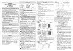
■ SDC45A (with 14-digit model No.)
All units have 2 digital inputs.
Basic Input Power Output Output Output Output Option Addition Addition
model model supply
1, 2
3, 4
5
6, 7
1
2
No.
C45A
Specifications
Standard model
1
1 full multiple input
2
2 full multiple inputs
A
100 to 240 Vac
1
1 form 1a1b relay
2
2 form 1a relays
C0
Current (output 3)
D0
Continuous voltage output (output 3)
V0
Voltage pulse (output 3)
RR
2 form 1a relays
CC
2 current outputs
VV
2 voltage pulse outputs
CV
Current (output 3) + voltage pulse
(output 4)
0
None
R
Form 1a relay
C
Current
D
Continuous voltage output
P
Transmitter power supply
0
None
0
None
1
8 digital inputs
2
8 digital outputs
3
8 digital outputs + RS-485 communication
0
None
T
Tropicalization treatment
K
Anti-sulfide treatment
D
Inspection certificate
B
Tropicalization treatment + inspection
certificate
L
Anti-sulfide treatment + inspection
certificate
Y
Complying with the traceability certification
0
None
1
LEDs: all orange
1-3
Chapter 1. OVERVIEW
■ SDC46A (with 14-digit model No.)
All units have 2 digital inputs.
Basic Input Power Output Output Output Output Option Addition Addition
model model supply
1, 2
3, 4
5
6, 7
1
2
No.
C46A
Standard model
1
1 full multiple input
2
2 full multiple inputs
A
100 to 240 Vac
1
1 form 1a1b relay
2
2 form 1a relays
C0
Current (output 3)
D0
Continuous voltage output (output 3)
V0
Voltage pulse (output 3)
RR
2 form 1a relays
CC
2 current outputs*
VV
2 voltage pulse outputs
CV
Current (output 3) + voltage pulse
(output 4)
0
None
R
Form 1a relay
C
Current*
D
Continuous voltage output
P
Transmitter power supply
0
None
1
Current (output 6)
2
Transmitter power supply (output 7)
3
2 current outputs*
4
Current (output 6) + transmitter power
supply (output 7)
* Cannot be selected when both "CC"
is selected for outputs 3 and 4 and
"C" is selected for output 5.
1-4
Specifications
0
None
1
12 digital inputs
2
12 digital inputs + 8 digital outputs
3
12 digital inputs + 8 digital outputs +
RS-485 communication
0
None
T
Tropicalization treatment
K
Anti-sulfide treatment
D
Inspection certificate
B
Tropicalization treatment + inspection
certificate
L
Anti-sulfide treatment + inspection
certificate
Y
Complying with the traceability certification
0
None
1
LEDs: All orange
Chapter 1. OVERVIEW
■ SDC45A/C46A (with 7-digit model No.)
Displays have all-orange LEDs.
Basic
model No.
Set No.
Option 1
Option 2
C45A
Standard model: Basic model, 2 alarm outputs
0
Basic
model No.
Specifications
Set No.
None
0
Regular type 1: 1 current + 2 relay outputs + 2 digital inputs
1
Regular type 2: 1 current + 1 voltage pulse + 1 relay output +
2 digital inputs
3
Regular type 3: 2 current outputs + transmitter power supply (24V)
+ 2 digital inputs
Option 1
0
None
1
Communications (RS-485) + PV input 2 + 8 digital outputs
2
PV input 2 + 8 digital outputs
3
8 digital outputs
4
PV input 2
Option 2
C46A
Specifications
Standard model: Basic model, 1 current output + 2 alarm outputs
0
None
0
Regular type 1: 1 current + 2 relay outputs + 2 digital inputs
1
Regular type 2: 1 current + 1 voltage pulse + 1 relay output +
2 digital inputs
3
Regular type 3 : 1 current + 2 relay outputs + transmitter power
supply (24V) + 2 digital inputs
0
None
1
Communications (RS-485) + PV input 2 + 12 digital inputs +
8 digital outputs
2
PV input 2 + 12 digital inputs + 8 digital outputs
3
12 digital inputs + 8 digital outputs
4
PV input 2
■ Accessories and optional parts
● Accessories
Name
Model No.
Mounting bracket
81405411-004
Gasket
(for SDC45A)
81421863-001
(for SDC46A)
81421864-001
● Optional parts
Name
Model No.
Mounting brackets (2)
81405411-003
Terminal cover*
81441420-001
* The SDC45A needs 1 terminal cover while
the SDC46A needs 2.
1-5
Chapter 1. OVERVIEW
1 - 3
Names and Functions of Parts
■ Front panel
● SDC45A
Mode indicator
● SDC46A
Loop number indicator
Mode indicator
Upper display
Auxiliary display
User function indicator
Mode indicator
Lower display
Auxiliary display
Lower display
[
], [
],[ ], [ ] key
[auto/man] key
User function indicator
Mode indicator
Multi-status indicator
Multi-status indicator
[display] key
Loop number indicator
Upper display
[auto/man] key
[display] key
[sp/ev] key
[enter] key
[sp/ev] key
[enter] key
[para] key
Loader jack
[para] key
Loader jack
[rsp/lsp] key
[at] key
[rsp/lsp] key
[at] key
[
], [
],[
], [
] key
[f1], [f2] key
● Description
Upper display:
Lower display:
Auxiliary display:
Displays PV (present temperature etc.) or setup items.
Displays SP (set temperature, etc.) and other parameters.
Displays group No., loop No., and channel No. of setup
item.
Multi-status indicator: Indicates MV or DI/DO status.
Mode indicators:
rdy:
Lights up in READY mode.
rsp:
Lights up in RSP (remote setting input) mode.
man:
Lights up in MANUAL mode.
out1-7:
Light up when the output is ON (SDC45A: out1-5).
Always lit when the output is current or continuous voltage.
User function indicators:
uf1-4:
Light under user-assigned conditions (SDC45A: uf1, uf2).
Loop number indicators:
pv1, pv2:
Light up to indicate which loop has the displayed PV
value.
[ ], [ ],[<], [>] keys: Used to increment/decrement numeric values and shift
between digits or settable items.
[auto/man] key:
Used to change AUTO/MANUAL mode.
[sp/ev] key:
Used to set the SP/EV bank.
[display] key:
Used to change the display contents in the operation display mode.
[para] key:
Used to set the PARA bank.
[enter] key:
Used in initiating setup and to confirm changed values.
[f1], [f2] key:
Used for user-assigned functions. (SDC46A only).
[at] key:
Used to execute/cancel auto-tuning, or for user-assigned
functions.
[rsp/lsp] key:
Used to change between remote and local set point, or for
user-assigned functions.
Loader jack:
Jack for connection of PC loader cable (with cap).
1-6
Chapter 1. OVERVIEW
■ Rear panel
The rear panel of this unit contains terminals used to connect the power supply,
inputs, and/or outputs.
For connections, always use crimp terminals suitable for M3 screws.
Terminal screws: M3
Tightening torque of terminal screws: 0.4 to 0.6 N·m or less
● SDC45A
Terminals
● SDC46A
Terminals
1-7
Chapter 1. OVERVIEW
1 - 4
Operation Modes
The following shows the transition of operation modes:
RUN + AUTO mode
READY + AUTO mode
LSP mode
RSP mode
AT stop
AT running
LSP mode
RUN/READY
AT stop
AUTO/MANUAL
AUTO/MANUAL
RUN + MANUAL mode
LSP mode
RSP mode
READY + MANUAL mode
RSP mode
RUN/READY
AT stop
LSP mode
RSP mode
AT stop
RUN:
Control status
READY:
Control stop status
AUTO:
Automatic operation (This unit automatically determines the MV
values.)
MANUAL:
Manual operation (The MV values are operated manually.)
LSP:
Local SP (The control is performed using the SP stored in the measuring instrument.)
RSP:
Remote SP (The analog input from the external device is used as SP.)
AT:
Auto tuning (The PID constants are set automatically using the limit
cycle.)
When performing the 2-loop control with a 2-input model, the operation mode can
be changed independently in each loop.
1-8
Chapter 2.
INSTALLATION
CAUTION
Use the SDC45A/46A within the operating ranges recommended in the
specifications (temperature, humidity, voltage, vibration, shock, mounting
direction, atmosphere, etc.).
Failure to do so might cause fire or faulty operation.
Do not block ventilation holes.
Doing so might cause fire or faulty operation.
■ Location
Install the controller in a location that meets the following criteria:
• Voltage to ground of 33 Vr.m.s. max., 46.7 V peak max., and 70 Vdc max.
• No high/low temperature/humidity.
• Free from sulfide gas or corrosive gas.
• Not dusty or sooty.
• Protected from direct sunlight, wind, and rain.
• Little mechanical vibration or shock.
• Not close to high voltage line, welding machine or other electrical noise generating source.
• At least 15 meters away from the high voltage ignition device for a boiler.
• No strong magnetic fields.
• No flammable liquid or gas.
■ External dimensions
● SDC45A
Unit: mm
11
48
43.8
130
Gasket
(accessory)
Mounting bracket
(accessory)
110
96
91.4
2
M3 terminal
screws
● SDC45A
Unit: mm
96
130
91.4
96
91.4
2
Gasket
(accessory)
Mounting bracket
(accessory)
110
11
M3 terminal
screws
2-1
Chapter 2. INSTALLATION
■ Panel cutout dimensions
Make the mounting holes according to the panel hole marking dimensions.
● SDC45A
Unit: mm
Stand-alone mounting
Gang-mounting
44+0.5
0
50 min.
92 +0.5
0
(48xN−4) +0.5
0
92 +0.5
0
50 min.
● SDC46A
Unit: mm
Gang-mounting
Stand-alone mounting
92 +0.5
0
+0.5
0
+0.5
0
92
92
(96xN−4) +0.5
0
50 min.
50 min.
Handling Precautions
• When used as a waterproof unit, be sure to install a gasket.
• When three or more units are gang-mounted horizontally, the maximum
allowable ambient temperature is 40 °C.
• Provide a space of at least 50 mm or more above and below the controller.
2-2
Chapter 2. INSTALLATION
■ Mounting procedure
• The mounting must be horizontal with the back not tilted more than 10° up or
down.
• The mounting panel should be rigid and no more than 7 mm thick (5 mm max.
when a gasket is used).
Handling Precautions
• When used as a waterproof unit, be sure to install a gasket.
● Ordinal mounting
Tools: Phillips-head screwdriver
(1) Insert this unit from the front of the panel.
(2) Fix the top and bottom of this unit firmly with the mounting brackets (accessory). When mounting this unit, mount the lower mounting bracket (a) first.
Panel
(b)
Mounting bracket
(accessory)
(a)
(3) To fasten this controller onto the panel, tighten the mounting bracket screws,
and turn one more turn when there is no play between the bracket and panel.
Handling Precautions
• Excessive tightening of the screws may deform the controller case.
2-3
Chapter 2. INSTALLATION
● Waterproof mounting
Tools: Phillips-head screwdriver
Screws for mounting bracket
Panel
(b)
Panel hole
Mounting bracket
(accessory)
Mounting bracket
mounting hole
Main body
(a)
Gasket (accessory)
Jack cover
(1) Mount the gasket on the flange part of this unit.
(2) Make sure that the jack cover is inserted to the front panel of this unit firmly.
(3) From the front of the panel, insert this unit with the gasket mounted.
(4) Fix the top and bottom of the main body firmly from the rear of the panel with
the mounting brackets (accessory).
When mounting this unit, mount the lower mounting bracket (a) first.
(5) To fasten this controller onto the panel, tighten a mounting bracket screws, and
turn one more turn when there is no play between the bracket and panel.
Handling Precautions
• Excessive tightening of the screws may deform the controller case.
• If gang-mounted, dustproof and waterproof protection may not be maintained.
2-4
Chapter 3.
3 - 1
WIRING
Wiring Precautions
WARNING
Before connecting the SDC45A/46A to the measurement target or to external
control circuits, make sure that the frame ground (FG) terminal is properly
grounded with an earth ground of less than 100 Ω. Failure to so might cause
an electric shock or fire.
Before wiring, removing or mounting the SDC45A/46A, be sure to turn the
power OFF. Failure to do so might cause electric shock or device failure.
Incorrect wiring of the SDC45A/46A can damage the SDC45A/46A and lead
to other hazards. Check that the SDC45A/46A has been correctly wired
before turning the power ON.
Do not touch electrically charged parts such as the power terminals. Doing
so might cause electric shock.
Do not disassemble the SDC45A/46A. Doing so might cause electric shock
or device failure.
CAUTION
Wire the SDC45A/46A properly using the specified types of wire and
following recognized installation methods. Failure to do so might cause
electric shock, fire or device failure.
Do not allow wire clippings, chips or water to enter the controller case. They
might cause fire or device failure.
Firmly tighten the terminal screws to the torque listed in the specifications.
Insufficient tightening of terminal screws might cause electric shock or fire.
Do not use unused terminals on the SDC45A/46A as relay terminals. Doing
so might cause electric shock, fire or device failure.
We recommend attaching the terminal cover (sold separately) after wiring the
SDC45A/46A. Failure to do so might cause electric shock.
Use the relays within the recommended service life. Failure to do so might
cause fire or device failure.
Use Yamatake Corporation's SURGENON if there is a risk of power surges
caused by lightning.
Otherwise, fire or device failure could result.
3-1
Chapter 3. WIRING
■ Wiring precautions
• Be sure to provide a switch within operator reach for shutting off the main
power supply to the controller in the main supply wiring. Also, the main supply
wiring also requires a time-lagged (T) fuse rated at 1.0 A, 250 V. (IEC127)
• Symbols in the terminal wiring label on the controller side:
Symbols
Meaning
AC power supply
DC power supply
Caution, danger of electric shock
Caution
• Before wiring the SDC45A/46A, verify the controller's model No. and terminal
Nos. written on the label on the side. Inspect all wiring once wiring work has
been completed.
• Use M3 crimp-type terminal lugs for wiring to terminals.
The tightening torque of the terminal screw must be 0.4 to 0.6 N·m or less.
• Leave a distance of at least 50 cm between I/O lead wires or communications
lead wires and power lead wires. Also, do not pass these lead wires through the
same conduit or wiring duct.
• Be careful not to allow any crimp-type terminal lugs to touch adjacent terminals.
• Be sure that any device or equipment which is connected to this controller has
adequate insulation for the controller's power supply voltage and maximum I/O
voltages.
• The controller requires 2 to 60 seconds according to the settings to start up once
the power is turned ON. A warm-up time of at least 30 minutes is recommended
to allow the controller to attain the specified accuracy.
3-2
Chapter 3. WIRING
3 - 2
Recommended Cables
• Contact the thermocouple wires to the terminals in case of a thermocouple input.
When a thermocouple is connected to terminals, or wiring distance is long, connect the wire via a shielded compensating lead wire.
• For input/output other than thermocouples, use a JCS 4364 instrument cable or
equivalent (generally called twisted shielded cable for instrumentation use).
Recommended twisted shielded cables are:
Fujikura Ltd.
Hitachi Cable, Ltd.
2 conductors
IPEV-S-0.9 mm2 × 1P
3 conductors
ITEV-S-0.9 mm2 × 1T
2 conductors
KPEV-S-0.9 mm2 × 1P
3 conductors
KTEV-S-0.9 mm2 × 1T
• A shielded multiconductor microphone cord (MVVS) may be used, if electromagnetic induction noise is comparatively low.
3-3
Chapter 3. WIRING
3 - 3
Terminal Connections
CAUTION
Firmly tighten the terminal screws to the torque listed in the specifications.
Insufficient tightening of terminal screws might cause electric shock or fire.
Do not use unused terminals on the SDC45A/46A as relay terminals. Doing
so might cause electric shock, fire or device failure.
We recommend attaching the terminal cover (sold separately) after wiring the
SDC45A/46A. Failure to do so might cause electric shock.
B or less
A
Applicable
screw size
M3
C or less
For wiring of SDC45A/46A, use an appropriate crimp type terminal lug suitable
for the M3 screw.
Terminal dimensions (mm)
A
B
C
6.1
5.8
5.8
Recommended
crimp terminal
JIS indication
RAV1.25-3
Applicable
electrical wire
size
0.3 to 1.3 mm2
AWG22 to 16
JST Mfg. Co.
Model No.
(Reference)
V1.25-3
V1.25 B3A
Handling Precautions
• When installing this unit in a place where the vibration or impact is large,
always use an appropriate round crimp type terminal lug to avoid loose
terminal connections.
• Pay special attention so that no crimp type terminal lugs are in touch with
adjacent terminals.
• The tightening torque of the terminal screw must be 0.4 to 0.6 N•m or
less.
3-4
Chapter 3. WIRING
3 - 4
Terminal Wiring Diagram
■ SDC45A terminals
A
C F
F
C
A
Description
Description
(1)
Power supply
(1) AC power
supply
100 to 240 Vac
(1)
(2)
1
1
Output 1, Output 2
(OUT1/OUT2)
(1)
(2)
COM(
C1
C1
C2
C2
C3
C3
C4
C4
C5
C5
C6
C6
C7
C7
C8
C8
)
Description
Digital
input/output
(DI/DO)
(1)DI
Other input
(1) Digital input
(DI)
F1
(2)DO
F2
Unused
(1) Relay (1a1b)
(2) Relay 2 (1a)
(1)
2
2
(1)
(2)
A
(3)
V/mA
(1)
(2)
Output 3 (OUT3)
(1) Relay
(2) Current,
voltage pulse,
continuous
voltage
B
mV
C
(1)
(1)
(2)
Output 4 (OUT4)
(2)
A
(3)
(1) Relay
(2) Current,
voltage pulse
DA
(1)
(2)
Output 5 (OUT5)
(1) Relay
(2) Current,
continuous
voltage,
transmitter
power supply
PV input 2 (PV2)
(1) Thermocouple
(2) Resistance
temperature
detector
(3) DC voltage/
current
RS-485
V/mA
PV input 1 (PV1)
(1) Thermocouple
(2) Resistance
temperature
detector
(3) DC voltage/
current
B
mV
DB
C
SG
3-5
Chapter 3. WIRING
■ SDC46A terminals
A
C
D
E F
D
C
A
(1)
Description
Description
Description
C1
D1
C2
(1)
(2)
1
1
Output 1,
Output 2
(OUT1/OUT2)
(1) Relay (1a1b)
D2
C3
D3
C4
(2) Relay 2 (1a)
D4
Output 6 (OUT 6)
2
2
Current
(1)
(2)
Output 3 (OUT3)
(1) Relay
(2)
D5
D6
(2) Current,
voltage pulse,
continuous
voltage
(1)
Digital input
(DI)
Digital input (DI)
Power supply
(1) AC power
supply
100 to
240Vac
Output 7 (OUT 7)
Current
Transmitter power
supply
Output 4 (OUT4)
(1) Relay
D7
D8
(2) Current,
voltage pulse
RS-485
DA
(1)
(2)
Unused
Output 5 (OUT5)
(1) Relay
(2) Current,
continuous
voltage,
transmitter
power supply
E
DB
SG
F
Description
COM( )
Description
Digital output
(DO)
(1)
Other input
(1) Digital input
(DI)
E1
F1
E2
F2
Unused
E3
E4
(1)
(2)
A
(3)
E5
V/mA
E6
PV input 2 (PV2)
(1) Thermocouple
(2) Resistance
temperature
detector
(3) DC voltage/
current
B
mV
E7
C
(1)
E8
(2)
A
(3)
Unused
V/mA
B
mV
C
3-6
PV input 1 (PV1)
(1) Thermocouple
(2) Resistance
temperature
detector
(3) DC voltage/
current
Chapter 3. WIRING
3 - 5
Power Supply Connections and Grounding
■ Power supply connections
WARNING
Before wiring, removing or mounting the SDC45A/46A, be sure to turn the
power OFF. Failure to do so might cause electric shock or device failure.
Instrument
power supply
200/200 V
100/100 V
Insulation
transformer
85 to 264 Vac
50/60Hz
Recommended
product
81446364-001
Line filter
This unit
1
E
3
1
2
2
4
3
Grounding
Grounding
Other circuits
Handling Precautions
• Obtain the SDC45A/46A power source from a single-phase instrumentation power source not subject to excess noise for AC model.
• If the power source generates noise, add an insulation transformer, and
use a line filter.
Line filter Yamatake Corporation Model No. 81446364-001
• Be careful not to bundle the primary and secondary coils of the power
cable together. Do not put them into the same conduit or duct after introducing noise-reduction measures.
■ Grounding
Connect the instrument by one-point grounding to FG terminal (terminal A-(3)).
Do not perform any jumper wiring. Mounting a grounding terminal board separately, and connect shielded cables, etc. to the ground, if grounding work is difficult.
Grounding resistance:
Less than 100 Ω
Grounding conductor:
Annealed copper wire more than 2 mm2 (AWG14)
Grounding conductor length: 20 m max.
A-column
3
FG terminal
Grounding terminal board
Grounding
(earth of less than 100
)
Shield
Handling Precautions
• Connect the instrument by one-point grounding to the FG terminal (terminals A-(3)). Do not perform any jumper wiring.
3-7
Chapter 3. WIRING
3 - 6
PV Input (PV) Connections
Handling Precautions
• Do not apply a voltage exceeding the allowable input voltage described
in the specifications to each input. Doing so might cause the unit to malfunction.
• Make the connections properly while carefully checking the input polarities.
• Always use shielded wires for input wiring.
• When using a thermocouple for the input, take appropriate measures so
that the terminal is not exposed to the wind. Failure to do so might cause
an error to occur.
■ PV input 1 (PV1) connection
•
Thermocouple sensor
• RTD sensor
F-column
• Linear voltage/linear current sensor
F-column
F-column
⑨
⑨
⑨
⑩
⑩
F-column
A
⑨
⑩
B
⑪
C
⑫
⑪
V/mA
⑩
⑪
⑪
⑫
⑫
mV
⑫
• When the range type is 43 to 46 (0 to 10 mV, -10 to +10 mV, 0 to 100 mV, -100
to +100 mV), terminal Nos. (11) and (12) are used.
• When the range type is 47 to 51 (0 to 1 V, -1 to +1 V, 1 to 5 V, 0 to 5 V, 0 to
10 V), terminal Nos. (10) and (11) are used.
■ PV input 2 (PV2) connection
•
Thermocouple sensor
F-column
• RTD sensor
• Linear voltage/linear current sensor
F-column
F-column
F-column
A
V/mA
B
C
mV
• When the range type is 43 to 46 (0 to 10 mV, -10 to +10 mV, 0 to 100 mV, -100
to +100 mV), terminal Nos. (7) and (8) are used.
• When the range type is 47 to 51 (0 to 1 V, -1 to +1 V, 1 to 5 V, 0 to 5 V, 0 to
10 V), terminal Nos. (6) and (7) are used.
3-8
Chapter 3. WIRING
3 - 7
Output (OUT) Connections
The terminal assignment may vary depending on the model No. Make the connections properly while carefully
checking the model No. and terminal No.
For details about terminal No. assignment, refer to:
3-4 Terminal Wiring Diagram (on page 3-5).
■ Relay output
Outputs 1 and 2
Relay (1a, 1b)
Relay (1a)
A-column
A-column
Load
1
Load
1
2
2
Load
Load
Output 3
Output 4
Output 5
A-column
A-column
A-column
Load
Load
Load
■ Current output, continuous voltage output, voltage pulse output, and power
supply for transmitter
Output 3
Output 4
Output 5
A-column
A-column
A-column
Load
Load
Output 6 (SDC46A only)
Output 7 (SDC46A only)
C-column
Load
Load
C-column
Load
Handling Precautions
• When opening or closing a micro current, use a bleeder resistance corresponding to the minimum open/close capacity of the relay to adjust it to a
sufficient current level.
• Do not connect or disconnect a load with the power to this unit turned
ON. Doing so might cause this unit or load to be faulty.
• Always use shielded wires to connect the current output or continuous
voltage output.
3-9
Chapter 3. WIRING
■ Connection with solid state relay (SSR)
To drive the SSR, a model having voltage pulse outputs must be used.
A constant current type SSR must be used. The following describes how to connect
the SSR.
The two conditions listed below must be satisfied.
• Input current (maximum): When the load current of the voltage pulse output is
satisfied, parallel connection can be made.
• Operating voltage range (input): Check that the voltage between the terminals
of the voltage pulse output is within the specified range.
● Yamatake's PGM10N/PGM10F series
This example shows the calculation for the connection of this unit and the
PGM10N015.
Note: For connection with other model number, check the specifications of each
model.
• Input current: Since the input current is 10 mA or less, up to three units (10 mA
× 3 = 30 mA ≤ 30 mA [maximum load current]) can be connected
in parallel.
• Operating voltage range (input): The rated voltage is 3.5 to 30 Vdc. Therefore,
the output voltage is within the range.
+15%
Output voltage = 12 Vdc −10%
Connection diagram
This unit
PGM10N/PGM10F
PGM10N/PGM10F
PGM10N/PGM10F
Number of connectable units
SSR
Connection
Number of connected units per output
PGM10N
Parallel connection
Up to 3 units
PGM10F
Parallel connection
Up to 2 units
● Omron's G3PA, G3PB, G3NA
• Input current: Since the input current is 7 mA or less, up to four units (7 mA × 4
= 28 mA ≤ 30 mA [maximum allowable current]) can be connected in parallel.
• Operating voltage range (input):
The operating voltage is 4 to 30 (32) Vdc or
9.6 to 30Vdc. Therefore, the output voltage is within the range.
+15%
Output voltage = 12 Vdc −10%
Connection diagram
This unit
G3PA
3-10
G3PA
G3PA
G3PA
Chapter 3. WIRING
Number of connectable units
SSR
Connection
Number of connected units per output
Omron G3PA
Parallel connection
Up to 4 units
Omron G3PB
Parallel connection
Up to 4 units
Omron G3NA
Parallel connection
Up to 4 units
■ Connection with transmitter (4 to 20 mAdc output)
When this unit is used for the power supply of the transmitter (4 to 20 mAdc output), use a model, the output of which has the power supply for the transmitter.
● Current input
24 Vdc
Transmitter
PV input (4 to 20 mA)
● Voltage input
24 Vdc
Transmitter
PV input (1 to 5 Vdc)
250 Ω precision resistor
Handling Precautions
• The power supply for the transmitter always outputs the voltage at the
same time when the power to this unit is turned ON.
Therefore, carefully check the connections before turning ON the power
to this unit.
Additionally, do not connect or disconnect the transmitter with the power
to this unit turned ON. Doing so might cause the transmitter to malfunction.
• Always use shielded wires for wiring.
3-11
Chapter 3. WIRING
3 - 8
Digital Input (DI) Connections
The terminal assignment may vary depending on the model No. Make the connections properly while carefully
checking the model No. and terminal No.
For details about terminal No. assignment, refer to:
3-4 Terminal Wiring Diagram (on page 3-5).
C-column
(SDC45A)
C-column
(SDC46A)
D-column
(SDC46A)
1
1
1
1
2
2
2
2
3
3
3
4
4
4
5
5
6
6
7
7
8
8
F-column
(common to SDC45A/46A)
Handling Precautions
• The digital input of this unit is a type of built-in power supply. Always use
dry contacts for external contacts.
• For dry contacts, always use a gold contact or other contact that can turn
ON or OFF the micro current. When using other relay contacts, the relay
contact may not be turned ON or OFF. Always use a contact having a
sufficient allowance of the minimum open/close capacity to the short-circuit terminal current and open-terminal voltage of this unit.
• If a semiconductor (open collector, etc.) is used for dry contact, use an
appropriate semiconductor that the voltage across the contact at both
ends when the contact is turned ON satisfies the allowable ON drop voltage. Additionally, use an appropriate semiconductor that the leak current
when the contact is turned OFF satisfies the allowable OFF leak current.
Internal circuit diagram of this unit to be connected to external switch input
Column other than F-column
F-column
7 Vdc
7 Vdc
1
1
2
2
Digital
input
7 Vdc
9
Internal circuit
3-12
Digital
input
3
Internal circuit
Chapter 3. WIRING
3 - 9
Digital Output (DO) Connections
C-column (SDC45A)
4.5 to 28 Vdc
Load
Load
Load
Load
Load
Load
Load
Load
1
2
3
4
5
6
7
8
E-column (SDC46A)
4.5 to 28 Vdc
Load
Load
Load
Load
Load
Load
Load
Load
1
2
3
4
5
6
7
8
Handling Precautions
• Do not make the positive (+) terminal of the external power supply shortcircuited with terminals (2) to (9) of C-column (SDC45A) or E-column
(SDC46A). If the positive (+) terminal is short-circuited with above terminals, this might cause the digital output to malfunction. (A short-circuit
protection circuit is not incorporated.)
• When connecting a semiconductor load, such as program controller
(sequencer), always select an appropriate module having the same current direction.
Additionally, do not use any semiconductor load, which is not operated
by the leak current when the digital output of this unit is turned OFF.
3-13
Chapter 3. WIRING
3 - 10
RS-485 Communication Connections
C-column
DA
DB
SG
Handling Precautions
• Be sure to connect the SG terminals each other. Failure to do so might
cause unstable communications.
• Attach 0.5 W or greater terminating resistor of 150 Ω ± 5 % at each end
of the communications lines.
• If units for which the connection of a terminating resistor is prohibited
(Yamatake SDC15/25/26/35/36 or DMC10) are on the same transmission line, do not connect a terminating resistor.
• Ground the shield FGs at one end in one location, not at both ends.
3-14
Chapter 3. WIRING
● Multiple 5-wire system units together
This unit or
3-wire system unit
(slave station)
DA
Terminating
resistor
DB
SG
FG
Master station
Shield
RDA
RDB
SDA
SDB
SG
FG
Shield
5-wire system unit
(slave station)
SDA
SDB
RDA
RDB
SG
FG
Shield
5-wire system unit
(slave station)
SDA
Terminating
resistor
SDB
RDA
RDB
SG
FG
Handling Precautions
• If units for which the connection of a terminating resistor is prohibited
(Yamatake SDC15/25/26/35/36 or DMC10) are on the same transmission line, do not connect a terminating resistor.
3-15
Chapter 3. WIRING
● 3-wire system
This unit or 3-wire system unit
(slave station)
DA
Terminating
resistor
DB
SG
FG
Master station
DA
Shield
DB
SG
Shield
This unit or 3-wire system unit
(slave station)
DA
DB
SG
FG
Shield
This unit or 3-wire system unit
(slave station)
DA
Terminating
resistor
DB
SG
FG
Handling Precautions
• If units for which the connection of a terminating resistor is prohibited
(Yamatake SDC15/25/26/35/36 or DMC10) are on the same transmission line, do not connect a terminating resistor.
3-16
Chapter 3. WIRING
3 - 11
Noise Generation Sources and Noise Suppression
Generally, it is thought that the following may be noise generation sources:
1. Relay and contacts
2. Solenoid coils and solenoid valves
3. Power line (higher than 90 Vac, in particular)
4. Inductive load
5. Motor commutator
6. Phase angle control SCR
7. Radio communication equipment
8. Welding machine
9. High-voltage ignition devices
The following shows effective measures for noise suppression:
1. A CR filter is effective for quick-rising noises such as impulse noise.
Recommended CR filter: Yamatake Corporation Model No. 81446365-001
2. A varistor is effective for noises with high crest values.
Be careful since the varistor is shorted if it malfunctions.
Recommended varistor
Yamatake Corporation Model No. : 81446366-001 (for 100 V)
81446367-001 (for 200 V)
Handling Precautions
• Take great care when using a varistor since the varistor becomes shortcircuited if it is faulty.
3-17
Chapter 3. WIRING
3 - 12
I/O Isolation
The following figure shows the mutual isolation between the input and output. In the following figure, sections
bounded by a solid line are isolated from the rest of the circuit. Sections bounded by a dotted line are not isolated
from the rest of the circuit.
OUT1
PV1
OUT2
OUT3
OUT4
PV2
DI-C1 to DI-C8
DI-D1 to DI-D8
DI-F1 to DI-F2
Internal
circuits
OUT5
OUT6
OUT7
DO-C1 to DO-C8
DO-E1 to DO-E8
RS-485 communication
Loader communication
The power circuit is isolated from all inputs/outputs, communications and internal circuits.
Handling Precautions
• The loader jack is not isolated from the internal circuits. Always put the
cap on the loader jack when the loader is not used.
3-18
Flowcharts for Major Settings
Chapters 4 to 7 describe the data settings of this unit.
To properly operate this unit, be sure to set each setting data
correctly so that it meets the operation of this unit.
When operating this unit for the first time, configure the settings in
the order shown below.
1.
2.
Setting of PARA bank
Setting of SP/EV bank
For details about data setting order in each setup, see the setting
fowcharts on the following pages:
A-1
1. Setting of PARA bank
● Key operations when setting or changing PARA bank
(1) Press the [display] key to return to the operation display.
(2) To select a bank, keep the [para] key pressed for 2 s.
(3) To display a bank to be set, press the [para] key, [ ] key, or [ ] key.
(4) When a desired bank is displayed, press the [enter] key.
(5) To display an item to be set, press the [para] key, [ ] key, [ ] key, [<] key, or [>] key.
(6) When a desired item is displayed, press the [enter] key.
(7) Change the set value with the [ ] key, [ ] key, [<] key, or [>] key.
(8) To set the set value you have changed, press the [enter] key.
(9) To set other items in the same bank, repeat the operation from step (5).
To set desired set data in other bank, continue the operation from step (2).
(10) To exit the setting, press the [display] key.
● Setting and operation flow
Start of key operation
[display] key → Keep the [para] key pressed for 2s. → Select a bank with [para] key, [ ] key, or [ ] key.
Initial setup
Setup bank (SETUP)
C-00 1
C-0 10
C-0 1 1
C-0 12
Loop type
Recipe enabled.
SP system group
Sampling cycle time
Page 4-1
Pages 6-15, 6-17
Pages 6-15, 6-17
Computer backup function is used.
Setup bank (SETUP)
PV1 input setup
PV bank (PV)
(Auxiliary display 1.)
PV2 input setup
PV bank (PV)
(Auxiliary display 2.)
C-002
Computer backup type
PV-0 1
Range type
PV-02
Decimal point position
PV-03 to PV-20 Linear scaling high/low limit,
filter, ratio, bias, etc.
Page 4-2
PV-0 1
Range type
PV-02
Decimal point position
PV-03 to PV-20 Linear scaling high/low limit,
Filter, ratio, bias, etc.
Page 4-2
Page 7-4
Page 4-4
Page 4-4
Approximation by linearization table is used.
Linearization table bank (TBL)
RSP multi-ratio is used.
SP configuration bank (SPCNF)
Internal contact input bank ( IC)
Control setup
Control bank (CTRL)
CNT.0 1
CNT.03
CNT.04
CNT.05 to CNT.06
TB.DP
Linearization decimal point
TB.A.0 1 to TB.B.20 Breakpoint
Page 7-8
RRA.0 1 to RRA.08 RSP ratio 1 to 8
I C0 1 to I C04
Operation type, input type, etc.
Page 7-6
Loop PV/SP /Decimal point position
Control action
Control algorithm
Control range high/low limit
Page 4-9
Page 4-4
Output at READY is changed.
MV bank (MV)
MV-0 1 to MV-03
Output at READY
Output at PV alarm is used.
MV bank (MV)
MV-04 to MV-05
Output at PV alarm
Fixed output value is used.
MV bank (MV)
MV-06 to MV-13 Fixed output value
Internal contact input bank ( I C) I C0 1 to I C04
Operation type, input type, etc.
SP configuration setup
SP configuration bank (SPCNF)
Continued on next page.
A-2
LMT.0 1 to LMT.02 SP high/low limit
Page 7-11
Continued from the previous page.
SP ramp is used.
SP configuration bank (SPCNF) CSP.0 1 to CSP.04 LSP ramp-up, ramp-down, etc.
Event configuration setup
Event configuration bank (EVCNF)
Output setup
Output bank (EVCNF)
EP-0 1 to EP-09
Operation type, Loop/Channel definition,
Polarity, Standby, Hysteresis, Delay, etc.
Page 5-14
Page 6-3
CO-0 1 to CO-07 Continuous output (current output, continuous voltage output)
TPO.0 1 to TPO.06 ON/OFF output, Time proportional output
Page 4-11
Approximation by linearization table is used.
Linearization table bank (TBL)
Digital output setup
Digital output bank (DO)
TB.DP
Linearization decimal point
TB.A.0 1 to TB.B.20 Breakpoint
Page 7-8
DO.C.0 1 to DO.C.02 Output type, Latch
DO.E.0 1 to DO.E.02 Output type, Latch
Digital input is used.
LPR.0 1 to LPR.06 SP group selection, RUN/READY,
AUTO/MANUAL, LSP/RSP, etc.
PR-0 1 to PR-02 Release all latches, OUT broken
line table use group
Internal contact input bank ( I C) I C0 1 to I C04
Operation type, Input type, etc.
Priority bank (PRIOR)
PID constant setup
Loop 1 PID bank (L 1.PI D)
Loop 2 PID bank (L2.PI D)
P-XX, I -XX, D-XX
OL-XX, OH -XX, RE-XX
P.XXC, I .XXC, D.XXC
(XX shows the PID group No.) OL.XXC, OH.XXC
Proportional band, Integration time, Derivative time
MV high/low limit, Manual reset
Proportional band (cool), Integration time (cool),
Derivative time (cool)
MV high/low limit (cool)
Zone PID is used.
Priority bank (PRIOR)
Control bank (CTRL)
LPR.02
ETD. 12 to ETD.20
PID group selection
Zone PID
Page 6-1
Page 6-9
Page 5-7
Page 6-1
Page 7-13
Event setup (For multi-SP)
Event setup bank (EV)
E0 1 to E 16.SB
Event 1 to 16, Main setting, Sub setting
Display or key is changed.
Display/key bank (HMI )
MS-0 1 to MS-05
FK-0 1 to FK-09
UFL.0 1 to UFL.02
RS-485 communication is used.
RS-485 communication bank (RS485)
Lock function is used.
Lock bank (LOCK)
MS display
[rsp/lsp] key, [at] key, [f1] key, [f2] key
"uf1 to uf4" lamp
COM.02 to COM.07
K.LOC 1 to K.LOC2
C.LOC 1 to C.LOC2
L.LOC 1 to L.LOC2
Page 6-3
to Station address,
Transmission speed, etc.
Page 7-15
Page 9-1
Key lock
RS-485 communication lock
Loader communication lock
Completion of key operation
[display] key
A-3
2. Setting of SP/EV bank
● Key operations when setting or changing SP/EV bank
(1) Press the [display] key to return to the operation display.
(2) To select a bank, keep the [sp/ev] key pressed for 2 s.
(3) To display a bank to be set, press the [sp/ev] key, [ ] key, or [ ] key.
(4) When a desired bank is displayed, press the [enter] key.
(5) To display an item to be set, press the [sp/ev] key, [ ] key, [ ] key, [<] key, or [>] key.
(6) When a desired item is displayed, press the [enter] key.
(7) Change the set value with the [ ] key, [ ] key, [<] key, or [>] key.
(8) To set the set value you have changed, press the [enter] key.
(9) To set other items in the same bank, repeat the operation from step (5).
To set desired set data in other bank, continue the operation from step (2).
(10) To exit the setting, press the [display] key.
● Setting and operation flow
Start of key operation
[display] key → Keep the [sp/ev] key pressed for 2s. → Select a bank with [sp/ev] key, [∨] key, or [∧] key.
SP group selection
SP group selection bank
SPNO
SP group
Page 5-8
Multi-SP setup (For multi-SP)
Multi-SP setup (For multi-SP)
(Auxiliary display L. 1.)
LSP.0 1∼LSP. 16
PI D.0 1 to PI D. 16
LSP of SP groups 1 to 16
PID group definition of SP groups 1 to 16
Page 6-15
LSP of SP groups 1 to 16
PID group definition of SP groups 1 to 16
Page 6-15
Multi-SP setup (2-loop and multi-SP are used.)
LSP.0 1∼LSP. 16
PI D.0 1 to PI D. 16
Loop 2 multi-SP bank
(Auxiliary display L.2.)
Completion of key operation
[display] key
Recipe setup (Recipe is used.)
Loop 1 recipe bank(L 1.REC)
(Auxiliary display 1.XX)
(XX shows the SP group No.)
SP
E0 1∼E08.SB
P, I, D
OL, OH, RE
P-C, I -C, D-C
OL.C, OH.C
OI
LSP
Event 1 to 8, main setting and sub setting
Proportional band, Integration time, Derivative time
MV high/low limit, Manual reset
Proportional band (cool), Integration time (cool), Derivative time (cool)
MV high/low limit (cool)
Initial output of PID control
Pages 5-1, 5-6
Recipe setup (2-loop and recipe are used.)
Loop 2 recipe bank(L2.REC)
(Auxiliary display 2.XX)
(XX shows SP group No.)
Completion of key operation
[display] key
A-4
SP
E09∼E 16.SB
P, I, D
OL, OH, RE
P-C, I -C, D-C
OL.C, OH.C
OI
LSP
Event 9 to 16, main setting and sub setting
Proportional band, Integration time, Derivative time
MV high/low limit, Manual reset
Proportional band (cool), Integration time (cool), Derivative time (cool)
MV high/low limit (cool)
Initial output of PID control
Pages 5-1, 5-6
Chapter 4.
4 - 1
FUNCTIONS NECESSARY FOR CONTROL
How to Set the Loop Type (2-input Model)
In the 2-input model, a desired loop type (control method) is selected by the settings.
■ Bank and settings
Bank
Item display
Item name
SETUP
C-00 1
Loop type
Settings
0: 1-loop, 1: 2-loop independent, 2: 1-loop with RSP,
3: Computer backup, 4: Internal cascade
0: 1-loop
1: 2-loop independent
2: 1-loop with RSP
PV1
PV1
PV2
PV1
P
I
D
P
I
D
P
I
D
P
I
D
PV2
(RSP)
3: Computer backup
PV1
PV2
(Host MV)
P
I
D
4: Internal cascade
PV1
(Master)
PV2
(Slave)
P
I
D
P
I
D
■ Setting procedures
(1) Keep the [para] key pressed for 2 s in the operation display status.
>> MOde is flashing on the upper display.
MODE
(2) Press the [ ] key or [para] key several times until SEtup is shown on the upper
display.
>> SEtup is flashing on the upper display.
SETUP
(3) Press the [enter] key.
>> C-00 1 is shown on the upper display.
C-00 1
0
(4) Press the [enter] key.
>> The value on the lower display starts flashing.
C-00 1
0
(5) Set a desired value with the [ ] key or [ ] key.
(6) Press the [enter] key to set the value.
(7) When the setting has been completed, press the [display] key.
>> The operation is then returned to the operation display status.
4-1
Chapter 4. FUNCTIONS NECESSARY FOR CONTROL
4 - 2
How to Set the Input Type
The input of this unit is a full-multi input method. The setting data is set properly according to the type of the signal
to be connected.
■ Bank and settings
Bank
Item display
Item name
Settings
pv
pv-0 1
Range type
See the list of input types shown on the next page.
■ Description of display
Bank name and item name
PV-0 1
Input No.
1.
51
Set value
The input No. can be changed with the [<] key or [>] key. (For 2-input model)
PV bank of input 1
PV-0 1
PV-02
•
•
•
[>] key
[<] key
PV bank of input 2
PV-0 1
PV-02
•
•
•
■ Setting procedures
● PV input bank
(1) Keep the [para] key pressed for 2s in the operation display status.
>> MOde is flashing on the upper display.
MODE
(2) Press the [ ] key or [para] key several times until Pv is shown on the upper display.
>> Pv is flashing on the upper display.
PV
(3) Press the [enter] key.
>> Pv-0 1 is shown on the upper display. At this time, check that 1. is shown
on the auxiliary display.
(To set input 2, change the value with the [>] key or [<] key.)
PV-0 1
1.
4-2
51
Chapter 4. FUNCTIONS NECESSARY FOR CONTROL
(4) Press the [enter] key.
>> The value on the lower display starts flashing.
(5) Set a desired value with the [ ] key or [ ] key.
(6) Press the [enter] key to set the value.
(7) When the setting has been completed, press the [display] key.
>> The operation is then returned to the operation display status.
■ Input types
The input indication accuracy may vary depending on the type of sensor.
For details, refer to:
Chapter 13, Specifications.
● Thermocouple
PV-0 1
set value
1
2
3
4
5
6
7
8
9
10
11
12
13
14
15
Sensor type
K
E
J
T
B
R
S
WRe5-26
PR40-20
Ni-Ni•Mo
N
PL II
DIN U
DIN L
Gold-iron/chromel
Range
-270.0
-270.0
-200.0
-270.0
0.0
-50.0
-50.0
0.0
0.0
0.0
-200.0
0.0
-200.0
-200.0
-273.0
to
to
to
to
to
to
to
to
to
to
to
to
to
to
to
+1372.0 °C
+1000.0 °C
+1200.0 °C
+400.0 °C
1800.0 °C
+1768.0 °C
+1768.0 °C
2300.0 °C
1900.0 °C
1300.0 °C
+1300.0 °C
1390.0 °C
+600.0 °C
+900.0 °C
+27.0 °C
-454
-454
-328
-454
32
-58
-58
32
32
32
-328
32
-328
-328
-459
to
to
to
to
to
to
to
to
to
to
to
to
to
to
to
+2502 °F
+1832 °F
+2192 °F
+752 °F
3272 °F
+3214 °F
+3214 °F
4172 °F
3452 °F
2372 °F
+2372 °F
2534 °F
+1112 °F
+1652 °F
+80 °F
● Resistance temperature detector (RTD)
PV-0 1
set value
21
22
31
32
Sensor type
PV-0 1
set value
41
42
43
44
45
46
47
48
49
50
51
Sensor type
Pt100
JPt100
Range
-200.0
-200.00
-200.0
-200.00
to
to
to
to
+850.0 °C
+300.00 °C
+640.0 °C
+300.00 °C
-328.0
-328.00
-328.0
-328.00
to +1562.0 °F
to +572.00 °F
to +1184.0 °F
to +572.00 °F
● DC voltage/DC current
Current
Voltage
Range
4
0
0
-10
0
-100
0
-1
1
0
0
to
to
to
to
to
to
to
to
to
to
to
20 mA
20 mA
10 mV
+10 mV
100 mV
+100 mV
1V
+1 V
5V
5V
10 V
4-3
Chapter 4. FUNCTIONS NECESSARY FOR CONTROL
4 - 3
How to Set Range-Related Items
Each range is set corresponding to the input type set in section 4-2, How to set an input type (on page 4-2).
■ Bank and settings
Bank
Item display
Item name
CTRL
CNT.05
Range low limit for control
Low limit of range used for PID control * This item must be set.
CNT.06
Range high limit for control
High limit of range used for PID control * This item must be set.
PV-04
Range low limit
Under-range is detected by the PV below this value.
PV-05
Range high limit
Over-range is detected by the PV exceeding this value.
PV-09
Linear scaling low limit
Value when the low limit of the linear signal is input.
* This item must be set when the linear input is selected.
PV-10
Linear scaling high limit
Value when the high limit of the linear signal is input.
* This item must be set when the linear input is selected.
PV
Settings
■ Range setup
This unit has one range for each input signal type.
Example: K thermocouple input: -270 to +1372 °C
Each range is set at the maximum range value, which can be input.
Therefore, to operate this unit at its optimal operating level, it is recommended to properly set each range after the input type has been selected.
Assuming that the range K of the selected input uses 0 to 800 °C and the range of
the input alarm uses -10 to +110 %,
-270 °C
+1372 °C
AL02 occurs.
AL0 1 occurs.
Range to be used actually
0 °C
Range low limit
for control
(CNT.05)
800 °C
Range high limit
for control
(CNT.06)
+880 °C
Range high limit
(PV-05)
-80 °C
Range low limit
(PV-04)
■ Setting procedures
Ctrl) (Range width for control)
● Control bank (C
Handling Precautions
• The range for control is a setting data related to the PID control. This
range affects the results of the auto tuning. Therefore, this range must
be set.
Set the full scale of the input range width to be used for actual operation as high
and low limit values.
Example: The K thermocouple uses a range of 0.0 to 800.0 °C
4-4
Bank
Item display
CTRL
CNT.05
Range low limit for control
Item name
CNT.06
Range high limit for control
Settings
0.0
800.0
Chapter 4. FUNCTIONS NECESSARY FOR CONTROL
(1) Keep the [para] key pressed for 2 s in the operation display status.
>> MOde is flashing on the upper display.
MODE
(2) Press the [ ] key or [para] key several times until CtrL is shown on the upper
display.
>> CtrL is flashing on the upper display.
CTRL
(3) Press the [enter] key.
>> Cnt.0 1 is shown on the upper display.
cnt.0 1
L. 1.
1
(4) Press the the [ ] key key several times until Cnt.05 is shown on the upper display.
>> Cnt.05 is shown on the upper display.
cnt.05
L. 1.
0.0
(5) Press the [enter] key.
>> The value on the lower display starts flashing.
cnt.05
L. 1.
0.0
(6) Set at 0.0 with the [ ] key or [ ] key.
(7) Press the [enter] key to set the value.
(8) In the same manner, return with the the [ ] key or [ ] key. Repeat the steps (4)
to (7) to configure the settings for Cnt.06.
(9) When all settings have been completed, press the [display] key.
>> The operation is returned to the operation display status.
● Features of this setting
As the range width for control is set, it is not necessary to readjust the
PID even when the setting is changed as described below.
• The input type is changed (K thermocouple → R thermocouple).
• The linear range (engineering range) is changed (0.0 to 5.0 kPa →
0.0 to 0.75 kPa).
4-5
Chapter 4. FUNCTIONS NECESSARY FOR CONTROL
● PV bank (high and low limits of linear range)
The high and low limits of the linear range need to be set when the DC voltage or
DC current is selected for the input type. Input high and low limit values corresponding to the output range (engineering range) of the connected unit.
Example: Setting when the pressure transmitter is connected (Pv-0 1 41: 4
to 20 mA is selected)
Specifications of transmitter
Output signal
Output range
Setting of this unit
Item display
Item name
Settings
4 mA DC
0.0 kPa
Pv-09
Linear scaling low limit
0.0
20 mA DC
10.0 kPa
Pv- 10
Linear scaling high limit
10.0
(1) Keep the [para] key pressed for 2 s in the operation display status.
>> MOde is flashing on the upper display.
MODE
(2) Press the [ ] key or [para] key several times until Pv is shown on the upper display.
>> Pv is flashing on the upper display.
PV
(3) Press the [enter] key.
>> Pv-0 1 is shown on the upper display. At this time, check that 1. is shown
on the auxiliary display.
(To set input 2, change the value with the [>] key or [<] key.)
PV-0 1
1.
51
(4) Press the [ ] key several times until Pv-09 is shown on the upper display.
>> Pv-09 is shown on the upper display.
PV-09
1.
0.0
(5) Press the [enter] key.
>> The value on the lower display starts flashing.
PV-09
1.
0.0
(6) Set at 0.0 with the [ ] key or [ ] key.
(7) Press the [enter] key to set the value.
4-6
Chapter 4. FUNCTIONS NECESSARY FOR CONTROL
(8) In the same manner, return with the [ ] key or [ ] key. Repeat the steps (4) to
(7) to configure the settings for Pv- 10.
(9) When the setting has been completed, press the [display] key.
>> The operation is returned to the operation display status.
● PV bank (Pv) (High and low limits of PV range)
PV range is set when a desired under range or over range to the selected input type
needs to be detected.
This unit detects an input error even in the initial setting status. However, it is recommended to set a PV range corresponding to the range area to be used actually.
Example: Setting to detect a level which is 10 % or less of the low limit and
a level which is +10 % or more of the high limit as an input error.
(Pv-0 1 1:K (-270.0 to +1372.0 °C) is selected.)
Range to be used
Setting of this unit
Item display
Item name
Low limit
0.0 °C
Pv-04
Range low limit
High limit
800.0 °C
Pv-05
Range high limit
Settings
-80.0
+880.0
(1) Keep the [para] key pressed for 2 s in the operation display status.
>> MOde is flashing on the upper display.
MODE
(2) Press the [ ] key or [para] key several times until Pv is shown on the upper display.
>> Pv is flashing on the upper display.
PV
(3) Press the [enter] key.
>> Pv-0 1 is shown on the upper display. At this time, check that 1. is shown
on the auxiliary display.
(To set input 2, change the value with the [>] key or [<] key.)
PV-0 1
1.
51
(4) Press the [ ] key several times until Pv-04 is shown on the upper display.
>> Pv-04 is shown on the upper display.
PV-04
1.
X999.9
4-7
Chapter 4. FUNCTIONS NECESSARY FOR CONTROL
(5) Press the [enter] key.
>> The value on the lower display starts flashing.
PV-04
1.
X999.9
(6) Set to (80.0 with the the [ ] key or [ ] key.
(7) Press the [enter] key to set the value.
(8) In the same manner, return with the [ ] key or [ ] key. Repeat the steps (4) to
(7) to configure the settings for Pv-05.
(9) When the setting has been completed, press the [display] key.
>> The operation is returned to the operation display status.
4-8
Chapter 4. FUNCTIONS NECESSARY FOR CONTROL
4 - 4
How to Set the Loop Control Action
The basic operation of the PID control is set.
Heat action:
Reverse action.
Control output decreases as the process value increases. Generally, this action is used for heating control.
Control output
Set value
100 %
0%
Proportional band
Process value
Cool action:
Direct action.
Control output increases as the process value increases. Generally, this action is used for cooling control.
Control output
Set value
100 %
0%
Proportional band
Process value
Heat/Cool action
Control output
Set value
Output (Heat)
Output (Cool)
100 %
0%
Proportional band
Process value
4-9
Chapter 4. FUNCTIONS NECESSARY FOR CONTROL
■ Bank and settings
Bank
Item display
Item name
Ctrl
Cnt.03
Control action
Settings
0: Reverse action (heat), 1: Direct action (cool),
2: Heat/Cool
■ Setting procedures
(1) Keep the [para] key pressed for 2 s in the operation display status.
>> MODE is flashing on the upper display.
MODE
(2) Press the [ ] key or [para] key several times until Ctrl is shown on the upper
display.
>> Ctrl is flashing on the upper display.
CTRL
(3) Press the [enter] key.
>> Cnt.0 1 is shown on the upper display.
cnt.0 1
L. 1.
1
(4) Press the [ ] key several times until Cnt.03 is shown on the upper display.
>> Cnt.03 is shown on the upper display.
cnt.03
L. 1.
0
(5) Press the [enter] key.
>> The value on the lower display starts flashing.
cnt.03
L. 1.
0
(6) Set a desired value with the [ ] key or [ ] key.
(7) Press the [enter] key to set the value.
(8) Press the [display] key.
>> The operation is returned to the operation display status.
4-10
Chapter 4. FUNCTIONS NECESSARY FOR CONTROL
4 - 5
How to Set Outputs (continuous output and time proportional output)
Up to seven output points can be mounted on the SDC46A while up to five points can be mounted on the SDC45A.
Setup items of each setting may vary depending on the type of output and operation method.
■ Output types, applications, and settings
Output No.
Output type
(Set by model No.)
Application
1 to 2
Relay
Time proportional output (MV)
Alarm output (EV)
3 to 7
Relay
Voltage pulse
Time proportional output (MV)
Alarm output (EV)
Current
Continuous voltage
Continuous output (MV)
Transmission output (PV, SP, etc.)
Power supply for transmitter
24 Vdc power supply
Bank
Item display
Out
tPo01 to 06
CO-01 to 07
None
-
■ Bank and settings
Bank
Item display
OUT
(Continuous
output)
OUT
(ON/OFF
output)
Item name
Settings
CO-0 1
Output range
Current output, 0: 4 to 20 mA, 1: 0 to 20 mA
Continuous voltage output, 0: 1 to 5 V, 1: 0 to 5 V, 2: 0 to 10 V
CO-02
Output type
0: Fixed at 0%, 1: MV, 2: Heat MV (for heat/cool control),
3: Cool MV (for heat/cool control), 4: PV (Loop), 5: SP,
6: Deviation (PV-SP), 7: PV (input channel)
For others, see the list of standard numeric values (on page
App.-15).
CO-03
Loop/channel definition
0: Invalid, 1: Loop 1/Channel 1, 2: Loop 2/Channel 2
CO-04
Output decimal position
0: No decimal point, 1: One digit below the decimal point, 2: Two
digits below the decimal point, 3: Three digits below the decimal
point, 4: Four digits below the decimal point
CO-05
Low limit of output scaling
-19999 to +32000 U (Value assigned to the low limit of the output)
CO-06
High limit of output scaling
-19999 to +32000 U (Value assigned to the high limit of the output)
CO-07
Linearization table group
definition
0: Not used., 1: 1 group, 2: 2 groups, 3: 3 groups, 4: 4 groups,
5: 5 groups, 6: 6 groups, 7: 7 groups, 8: 8 groups
tpO.0 1
Output type
0: OFF, 1: MV of loop 1,
2: Heat MV of loop 1 (for heat/cool control),
3: Cool MV of loop 1 (for heat/cool control), 4: MV of loop 2
5: Heat MV of loop 2 (for heat/cool control),
6: Cool MV of loop 2 (for heat/cool control)
For others, see the list of standard bit Nos. (on page App.-14).
tpO.02
Latch
0: Not latched., 1: Latched when turned ON., 2: Latched when
turned OFF. (Except for OFF when power is turned ON.)
tpO.03
Time proportional operation
type
0: Priority on controllability, 1: Priority on device life
tpO.04
Min. ON/OFF time
0 to 300 ms
tpO.05
Time proportional cycle
Relay output, 5.0 to 120.0 s
Voltage pulse output, 0.1 to 120.0 s
tpO.06
Linearization table group
definition
0: Not used., 1: group 1, 2: group 2, 3: group 3, 4: group 4,
5: group 5, 6: group 6, 7: group 7, 8: group 8
Handling Precautions
• Note that some items cannot be set depending on the output type.
CO-0 1 to CO-07: Valid when the current or continuous voltage output is
used.
TPO.0 1 to TPO.06: Valid when the relay or voltage pulse output is used.
4-11
Chapter 4. FUNCTIONS NECESSARY FOR CONTROL
■ Description of display
Bank name and item name
CO-0 1
Output No.
1.
0
Set value
The output No. can be changed with the [<] key or [>] key.
Output bank
of output 1
CO-0 1
CO-02
•
•
•
[>] key
[<] key
Output bank
of output 2
CO-0 1
CO-02
•
•
•
[>] key
[<] key
Output bank
of output 7
CO-0 1
CO-02
•
•
•
■ Setting procedures
(1) Keep the [para] key pressed for 2 s in the operation display status.
>> MODE is flashing on the upper display.
MODE
(2) Press the [ ] key or [para] key several times until Out is shown on the upper
display.
>> Out is flashing on the upper display.
OUT
(3) Press the [enter] key.
>> cO-0 1 is shown on the upper display.
(To set input 2, change the value with the [>] key or [<] key.)
cO-0 1
1.
0
(4) Press the [enter] key.
>> The value on the lower display starts flashing.
cO-0 1
1.
0
(5) Set a desired value with the [ ] key or [ ] key.
(6) Press the [enter] key to set the value.
(7) In the same manner, return with the [ ] key or [ ] key. Repeat the steps (3) to
(6) to configure the settings for cO-02 to cO-07 and tpO.0 1 to tpO.06.
(8) When all settings have been completed, press the [display] key.
>> The operation is returned to the operation display status.
4-12
Chapter 4. FUNCTIONS NECESSARY FOR CONTROL
■ Continuous output setup
In the output range (cO-0 1), a scaling-calculated current of 0 to
100 % or a continuous voltage range is set.
In the output type (cO-02) and loop/channel definition (cO-03), data is set which
becomes the input for scaling calculation.
In the output decimal point position (cO-04), the decimal point position is set for
the low limit of the output scaling (cO-05) and the high limit of the output scaling
(cO-06).
The output of the scaling calculation using the low limit of the output scaling (cO05) and the high limit of the output scaling (cO-06) becomes as shown in the
Figure below.
Output (%)
Output (%)
110
100
110
100
0
-10
Input
Low limit
High limit
Low limit < High limit
0
-10
Input
High limit
Low limit
Low limit > High limit
However, when the output range is 0 to 20 mA, 0 to 5 V, or 0 to 10 V, the output
becomes 0 to 110 %.
In the linearization table group definition (cO-07), you can set so that the scaling
calculation to the linearization approximation value is performed.
Additionally, by setting the linearization table group (Pr1Or) of the priority bank
(Pr-02), you can change to the internal contact input definition.
4-13
Chapter 4. FUNCTIONS NECESSARY FOR CONTROL
■ Time proportional output setup
When the output type (tpO.0 1) is set to 1 to 6, the time proportional value is output
according to the settings of the time proportional cycle (tpO.05).
According to the time proportional operation type (tpO.03), the time proportional
output becomes as follows.
When "0: Priority on controllability" is set, the output may be turned ON twice or
more within the time proportional cycle. On the contrary, when "1: Priority on
device life" is set, the output is turned ON zero time to once within the time proportional cycle.
"0" is set.
Time proportional cycle
Time proportional cycle
ON
OFF
PID control result
"1" is set.
25 %
65 %
Time proportional cycle
45 %
Time proportional cycle
ON
OFF
PID control result
25 %
65 %
45 %
The min. ON/OFF time (tpO.04) is valid. However, even though "0" is set, the
min. ON/OFF time becomes 1 ms. In the relay output, even though a value less
than "50" is set, the min. ON/OFF time on the operation is 50 ms.
The linearization table group definition (tpO.06), can be set so that the time proportional output corresponding to the linearization approximation value is made.
Additionally, by setting the linearization table use group (Pr1Or) for OUT of the
priority bank (Pr-02), you can change to the internal contact input definition. The
latch (tpO.02) becomes invalid.
■ ON/OFF output setup
When the output type (tpO.0 1) is set at "0", the output becomes the OFF output.
When any of the standard bit Nos. 1024 to 2047 is set in the output type (tpO.0 1),
the ON/OFF status of this standard bit is output.
The latch (tpO.02) and the min. ON/OFF time (tpO.04) are valid.
Additionally, even though a value less than "50" is set in the relay output, the min.
ON/OFF time on the operation is 50 ms.
The time proportional operation type (tpO.03), time proportional cycle (tpO.05),
and linearization table group definition (tpO.06) are invalid.
4-14
Chapter 5.
5 - 1
OPERATION AND GENERAL FUNCTIONS
Operation Displays
Every time the [display] key is pressed, the display is changed as follows.
The display change does not affect the control. Therefore, this unit can be operated with a desired display selected.
■ 1-loop
■ 2-loop independent
Upper display: PV value
Upper display: PV1 value
Lower display: SP value
Lower display: PV1 value
Upper display: PV value
Upper display: PV1 value
Lower display: MV value
Lower display: SP1 value
Upper display: PV value
Upper display: PV1 value
Lower display: Output (Heat)
Lower display: MV1 value
Upper display: PV value
Upper display: PV1 value
Lower display: Output (Cool)
Lower display: Output 1 (Heat)
Upper display: PV1 value
Lower display: Output 1 (Cool)
Displayed only when heat/cool control is selected.
Upper display: PV2 value
Lower display: SP2 value
Upper display: PV2 value
Lower display: MV2 value
Upper display: PV2 value
Lower display: Output 2 (Heat)
Upper display: PV2 value
Lower display: Output 2 (Cool)
5-1
Chapter 5. OPERATION AND GENERAL FUNCTIONS
■ 1-loop with RSP
■ Computer backup
Upper display: PV value
Upper display: PV value
Upper display: PV value
Lower display: LSP value
Lower display: RSP value
Lower display: SP value
Upper display: PV value
Upper display: PV value
Upper display: PV value
Lower display: MV value
Lower display: LMV
Lower display: RMV
Upper display: PV value
Lower display: Output (heat)
Upper display: PV value
Lower display: Output (cool)
Upper display: PV value
Lower display: Output (heat)
Upper display: PV value
Lower display: Output (cool)
Displayed only when heat/cool control is selected.
LMV: Local MV (PID control output of this unit)
RMV: Remote MV (MV output from host station)
5-2
Chapter 5. OPERATION AND GENERAL FUNCTIONS
■ Internal cascade
Upper display: PV1 value
Lower display: PV2 value
Upper display: PV1 value
Lower display: SP1 value
Upper display: PV1 value
Lower display: MV1 value
Upper display: PV2 value
Upper display: PV2 value
Lower display: LSP value
Lower display: RSP value
Upper display: PV2 value
Lower display: MV2 value
Upper display: PV2 value
Lower display: Output 2 (heat)
Upper display: PV2 value
Lower display: Output 2 (cool)
Upper display: PV1 value
Lower display: SMV value
Displayed only when the slave selects heat/cool control.
SMV: MV output on slave side
PV1: PV on master side
PV2: PV on slave side
5-3
Chapter 5. OPERATION AND GENERAL FUNCTIONS
■ Display status of mode indicator lamps
When two loops are operated independently, two PID controls are executed in the
internal cascade control. Therefore, according to the displayed PV input No., each
mode indication LED is lit, flashing, or off with the patterns shown in the tables
below.
Meaning of display
❍ : Lit.
: Flashing
: Off
• "rdy" LED
Mode
Display
PV1
PV2
PV1, PV2
Other
Loop 1: RUN
Loop 2: RUN
×
×
×
×
Loop 1: READY
Loop 2: RUN
❍
❍
❍
Loop 1: RUN
Loop 2: READY
Loop 1: READY
Loop 2: READY
❍
❍
❍
PV1
PV2
PV1, PV2
Other
Loop 1: AUTO
Loop 2: AUTO
×
×
×
×
Loop 1: MANUAL
Loop 2: AUTO
❍
❍
❍
• "man" LED
Mode
Display
Loop 1: AUTO
Loop 2: MANUAL
Loop 1: MANUAL
Loop 2: MANUAL
❍
❍
❍
• "rsp" LED
Mode
Loop 1: LSP
Loop 2: LSP
Loop 1: LSP
Loop 2: RSP
5-4
Display
PV1
PV2
PV1, PV2
Other
×
×
×
×
❍
Chapter 5. OPERATION AND GENERAL FUNCTIONS
5 - 2
How to Change the SP
■ Setting procedures
The following describes an example that the LSP1 is changed when using the
multi-SP:
(1) Keep the [sp/ev] key pressed for 2s in the operation display status.
>> SPNO is flashing on the upper display.
SPNO
(2) Press the [ ] key or [sp/ev] key several times until L 1.LSP is shown on the
upper display.
>> L 1.LSP is flashing on the upper display.
L 1.LSP
(3) Press the [enter] key.
>> LSP.0 1 is shown on the upper display. At this time, check that the auxiliary display shows L.1. This shows that the loop 1 is currently active.
LSP.0 1
L. 1.
0. 1
(4) Press the [enter] key.
>> The value on the lower display starts flashing.
LSP.0 1
L. 1.
0. 1
(5) Set a desired value with the [
] key or [
] key.
(6) Press the [enter] key to set the value.
(7) When the setting has been completed, press the [display] key.
>> The operation is then returned to the operation display status.
Note
• When changing LSP1 of loop 2, select L2.LSP in step (2).
• When using the recipe, change the LSP1 from the loop 2 recipe bank (bank display: L2.REC) of the SP/EV bank.
5-5
Chapter 5. OPERATION AND GENERAL FUNCTIONS
5 - 3
How to Change the SP Group/Recipe Group
When multi-SP group and multiple recipe groups are set, the SP group and recipe group used for control can be
changed.
The multi-SP/recipe is set using the setup bank.
For details, refer to:
6-5 How to Use the Multi-SP (on page 6-15 )
6-6 How to Use Recipes (on page 6-17)
■ Setting procedures
(1) Keep the [sp/ev] key pressed for 2s in the operation display status.
>> SPNO is flashing on the upper display.
SPNO
(2) Press the [enter] key.
>> Check that the auxiliary display shows L.1.. This shows that the loop 1 is
currently active. If you want to change it to loop 2, change the value with
the [ ] key, [ ] key, [>] key or [<] key.
SPNO
L. 1.
1
(3) Press the [enter] key.
>> The value on the lower display starts flashing.
SPNO
L. 1.
1
(4) Set a desired value with the [
] key or [
] key.
(5) Press the [enter] key to set the value.
(6) When the setting has been completed, press the [display] key.
>> The operation is then returned to the operation display status.
Handling Precautions
• When "SP group selection/recipe group selection" of the function priority
(loop) is set with the internal given high priority, the group cannot be
changed using the key operation.
For details, refer to:
6-1 How to Set the Priority (on page 6-1).
5-6
Chapter 5. OPERATION AND GENERAL FUNCTIONS
5 - 4
How to Change the PID (auto tuning)
■ Starting procedures
(1) Check that the PV inputs and final control elements (heater power supply, etc.)
are connected correctly and that the unit is ready for control.
(2) Press the [display] key to display the loop, in which the AT (auto tuning) is
executed. (PV1 or PV2: For 2-input model)
(3) Check that the displayed loop is in the RUN and AUTO modes.
(4) Keep the [at] key pressed for 2s. (The function key registration is set in the initial settings.)
>> The display status of AT.ON on the lower display changes from flashing to
lit. The AT is then started.
■ Stopping procedures
Normally, the AT completes automatically. To stop the AT while it is running,
keep the [at] key again pressed for 2s.
>> The display status of AT.OF on the lower display is then changed from flashing
to lit. The AT is then stopped.
Additionally, the AT is also stopped when the operation mode is changed to
the READY mode or MANUAL mode.
■ Display while AT is running
The "uf1" LED is flashing while the AT of the loop 1 is running.
(The user function indicator lamp setting is set at the initial value.)
When the AT has been completed and the PID has been obtained, the "uf1" LED is
turned off.
The new PID value is written into the PID group currently being used.
Since no display is given while the AT of the loop 2 is running, set the user function indicator lamp when necessary.
PV-0 1
1.
PV-0 1
51
1.
Flashing while
AT is running
51
Goes off when AT is
stopped and PID is
obtained
Handling Precautions
• Before starting the AT, check the PV inputs or final control elements are
connected correctly. Make the control operation ready to start.
• To start the AT, it is preconditioned that the PV input error does not occur
in the RUN mode and AUTO mode.
• For 2-input models, the AT cannot be started when both the PV1 and
PV2 are displayed.
With the [display] key, change the display to a loop you want to run the
AT.
• If the READY mode or MANUAL mode is changed, or PV input error or
power failure occurs while the AT is running, the AT is completed without
changing of the PID constants.
5-7
Chapter 5. OPERATION AND GENERAL FUNCTIONS
5 - 5
How to Change the PID (manual)
■ Setting procedures
The following describes an example that the PID is changed when using the multiSP:
(1) Keep the [para] key pressed for 2s in the operation display status.
>> MODE is flashing on the upper display.
MODE
(2) Press the [ ] key or [para] key several times until L 1.PI D is shown on the
upper display.
>> L 1.PI D is flashing on the upper display.
L 1.PI D
(3) Press the [enter] key.
>> P-0 1 is shown on the upper display. This shows the proportional band of
the 1st group. To change the PID group, change it with the [<] key or [>]
key.
P-0 1
L. 1.
5.0
(4) Select an item you want to set with the [ ] key or [ ] key.
>> The selected item is shown on the upper display.
(5) Press the [enter] key.
>> The value on the lower display starts flashing.
(6) Set a desired value with the [
] key or [
] key.
(7) Press the [enter] key to set the value.
(8) When the setting has been completed, press the [display] key.
>> The operation is then returned to the operation display status.
Note
• To change the PID group of the loop 2, select L2.PID in step (2). When using the
recipe, change the PID from the recipe bank (L2.REC) of the loop 2 of the
SP/EV bank.
5-8
Chapter 5. OPERATION AND GENERAL FUNCTIONS
5 - 6
How to Change the Event Action Point
The event action point setting procedures may vary depending on the setting of the recipe enabled setup of the setup
bank (item display: C-0 10), that is, multi-SP and recipe.
• If multi-SP use is set.
The event action point is set using the event setup bank.
The event action point setting consists of one set of main setting and sub
setting for each event No.
• If recipe use is set.
The action points of events 1 to 8 are set using the loop 1 recipe bank
while the action points of events 9 to 16 are set using the loop 2 recipe
bank.
The event action point setting consists of main settings and sub settings
equivalent to the number of SP groups for each event No.
■ Setting procedures (for multi-SP)
(1) Keep the [sp/ev] key pressed for 2s in the operation display status.
>> SPNO is flashing on the upper display.
SPNO
(2) Press the [ ] key or [sp/ev] key several times until EV is shown on the upper
display.
>> EV is flashing on the upper display.
EV
(3) Press the [enter] key.
>> The main setting of the action point 1 group is shown on the upper display.
E0 1
0
(4) Select an item you want to set with the [ ] key or [ ] key.
>> The selected item is shown on the upper display.
(5) Press the [enter] key.
>> The value on the lower display starts flashing.
(6) Set a desired value with the [
] key or [
] key.
(7) Press the [enter] key to set the value.
(8) When the setting has been completed, press the [display] key.
>> The operation is then returned to the operation display status.
5-9
Chapter 5. OPERATION AND GENERAL FUNCTIONS
■ Setting procedures (for recipe)
(1) Keep the [sp/ev] key pressed for 2s in the operation display status.
>> SPNO is flashing on the upper display.
SPNO
(2) Press the [ ] key or [sp/ev] key several times until L1.REC is shown on the
upper display. (L2.REC for loop 2 recipe)
>> L1.REC is flashing on the upper display.
L1.REC
(3) Press the [enter] key.
>> The SP of the recipe group 1 of the loop 1 is shown on the upper display.
SP
1.0 1.
0.0
(4) Select an item you want to set with the [ ] key.
>> The main setting of the event 1 group is shown.
E0 1
1.0 1.
0.0
(5) Every time the [ ] key is pressed, the display changes until the sub setting of
the event 8 group is shown.
>> The selected item is shown on the upper display.
(6) Press the [enter] key.
>> The value on the lower display starts flashing.
(7) Set a desired value with the [
] key or [
] key.
(8) Press the [enter] key to set the value.
(9) When the setting has been completed, press the [display] key.
>> The operation is then returned to the operation display status.
Handling Precautions
• If the operation type of the event is not set, "-----" is shown on the
lower display and the setting cannot be configured.
5-10
Chapter 5. OPERATION AND GENERAL FUNCTIONS
5 - 7
How to Start and Stop the Control Operation (RUN/READY)
■ Setting procedures
(1) Keep the [para] key pressed for 2s in the operation display status.
>> MODE is flashing on the upper display.
MODE
(2) Press the [enter] key.
>> R---R is shown on the upper display. At this time, check that the auxiliary display shows L.1. This shows that the loop 1 is currently active. If you
want to change it to loop 2, change the value with the [ ] key, [ ] key,
[>] key or [<] key.)
R---R
L. 1.
RUN
(3) Press the [enter] key.
>> The value on the lower display starts flashing.
R---R
L. 1.
RUN
(4) Set a desired mode with the [
RUN: RUN mode
RDY: READY mode
] key or [
] key.
(5) Press the [enter] key to set the value.
(6) Press the [display] key.
>> The operation is then returned to the operation display status.
5-11
Chapter 5. OPERATION AND GENERAL FUNCTIONS
5 - 8
How to Manually Output the MV (AUTO/MANUAL)
This function is intended to change the MV using the key operation regardless of the operation status of the instrument.
■ Setting procedures
(1) In the operation display status, press the [display] key to display a loop you
want to put it in the manual mode. (This operation is valid only for 2-loop models.)
(2) In the operation display status, keep the [auto/man] key pressed for 2s.
>> The display status of MAN on the lower display changes from flashing to lit
(operation mode changes to the manual operation mode) and the numeric
value starts flashing. (The "man" LED is lit.)
(3) Change the output value to a desired level with the [ ] key, [ ] key, [<] key,
or [>] key.
>> The MV changes in synchronization with the key operation. (It is not necessary to press the [enter] key.)
(4) To return to the auto mode, keep the [auto/man] key again pressed for 2s.
>> The display status of AUTO on the lower display changes from flashing to
lit and the operation mode changes to the auto mode. (The "man" LED is
off.)
Handling Precautions
• For 2-input models, when PV1 and PV2 are displayed at the same time,
the mode cannot be changed. With the [display] key, change the display
to a loop you want to run.
Note
• Bumpless (MV before change continues) or preset value can be selected for the
MV when changing the manual mode.
For details about settings, refer to:
"Output operation at changing Auto/Manual" (ETD.03) of the control
bank.
5-12
Chapter 5. OPERATION AND GENERAL FUNCTIONS
5 - 9
How to Change to the Remote SP (RSP/LSP)
When the loop with the RSP or internal cascade is selected in the 2-input model, a set value to be used can be selected from the remote or local.
■ How to change to the remote SP (RSP)
(1) In the operation display status, keep the [rsp/lsp] key pressed for 2s.
(The function key registration is set at the initial setting.)
When using the internal cascade control, perform the operation with PV2 displayed.
>> The display status of rSP on the upper display changes from flashing to lit
and the mode changes to the remote SP mode. (The "rsp" LED is lit.)
■ How to change to the local (LSP)
(1) In the operation display status, keep the [rsp/lsp] key pressed for 2s.
When using the internal cascade control, perform the operation with PV2 displayed.
>> The display status of LSP on the upper display changes from flashing to lit
and the mode is changed to the local SP mode. (The "rsp" LED is turned
off.)
Handling Precautions
• For 2-input models, when PV1 and PV2 are displayed at the same time,
the mode cannot be changed. With the [display] key, change the display
to a loop you want to run.
Note
• When changing the remote SP to the local SP, the remote SP immediately before
changing is written to the local SP, enabling the continuous control. (RSP tracking function)
For details about setting, refer to:
RSP tracking (CSP.04) of SP configuration bank.
5-13
Chapter 5. OPERATION AND GENERAL FUNCTIONS
5 - 10
How to Change the SP with Constant Ramp
When changing the set value of the LSP or the SP group selection, it is possible to change the SP with a constant SP
ramp.
LSP is changed
New SP
LSP ramp-up
Previous SP
Time
SP is changed
Previous SP
LSP ramp-down
LSP is changed
New SP
Time
SP is changed
■ Bank and settings
Bank
SPCNF
Item display
CSP.0 1
Item name
SP ramp unit
Settings
0: No decimal point/s, 1: No decimal point/min,
2: No decimal point/h, 3: 0.1/s, 4: 0.1/min, 5: 0.1/h,
6: 0.01/s, 7: 0.01/min, 8: 0.01/h, 9: 0.001/s, 10: 0.001/min,
11: 0.001/h
CSP.02
SP ramp-up for LSP
0 U (No ramp)
1 to 32000 U (Decimal point position may vary depending on
the SP ramp unit.)
CSP.03
SP ramp-down for LSP
0 U (No ramp)
1 to 32000 U (Decimal point position may vary depending on
the SP ramp unit.)
■ Setting procedures
(1) Keep the [para] key pressed for 2s in the operation display status.
>> MODE is flashing on the upper display.
MODE
(2) Press the [ ] key or [para] key several times until SPCNF is shown on the
upper display.
>> SPCNF is flashing on the upper display.
SPCNF
5-14
Chapter 5. OPERATION AND GENERAL FUNCTIONS
(3) Press the [enter] key.
>> LMT.0 1 is shown on the upper display. At this time, check that the auxiliary
display shows L.1. This shows that the loop 1 is currently active.
LMT.0 1
L. 1. X999.9
(4) Press the [ ] key several times until CSP.0 1 is shown on the upper display.
>> CSP.0 1 is flashing on the upper display.
CSP.0 1
L. 1.
0
(5) Press the [enter] key.
>> CSP.0 1 is shown on the lower display.
CSP.0 1
L. 1.
0
(6) Set a desired value with the [
] key or [
] key.
(7) Press the [enter] key to set the value.
(8) In the same manner, return with the [ ] key or [ ] key. Repeat the steps (4) to
(7) to configure the settings for CSP.02 to CSP.03.
(9) When settings have been completed, press the [display] key.
>> The operation is returned to the operation display status.
■ Conditions for ramp start
• LSP value is changed.
• SP group (multi-SP group/recipe group) is changed.
• Mode is changed from RSP to LSP.
■ Conditions for ramp start with PV used as start point
If any of the following arises, the ramp is started with PV used as start point instead
of the previous SP:
• The power is turned ON.
• The MANUAL mode is changed to the AUTO mode.
• The READY mode is changed to the RUN mode.
• The through output is changed to the backup mode.
• The fixed value output is released.
• The "Loop type" item of the setup bank is changed.
Handling Precautions
• The ramp setting for the RSP is invalid.
5-15
Chapter 6.
6 - 1
FUNCTIONS OFTEN USED FOR
OPERATIONS OTHER THAN CONTROL
How to Set the Priority
In the functions, one of set value, internal contact input (digital input), and other conditions can be used as conditions for operation change. What condition is used is set by the priority.
■ Setting bank
Priority bank (PRI OR)
■ Example: Selection of SP group
The following describes an example that the SP group selection function is used for
four SP groups.
Set value (SP group selection) or internal contact input (digital input) is used for
conditions for SP group selection is determined by the priority.
● SP group of control loop 1 is selected by the set value (SP group selection).
Configure the settings as shown below in the priority bank (PRI OR) setup.
Display item
LPR.0 1
(Valid)
Auxiliary display
1.
Item name
Setting
(Loop 1) SP group selection
Set value
(SP group
selection: SPNO)
0: Set value priority
Internal contact input (Invalid)
Digital input Logical operation Event Other
Priority setup: Set value priority
SP 1 group
SP 2 group
SP 3 group
SP group selection
function
Selected SP group
SP 4 group
When the priority setup is set at "Set value priority," the SP group selection function operates according to the set value of the SP group selection.
The SP group selection with the digital input is set for the internal contact input as
shown in the Figure above. However, since the priority setup is set at "Set value
priority," the SP group selection does not operate even though the digital input is
operated.
6-1
Chapter 6. FUNCTIONS OFTEN USED FOR OPERATIONS OTHER THAN CONTROL
● SP group of control loop 1 is selected by the internal contact input (digital input).
Configure the settings as shown below in the priority bank (PRI OR) setup.
Display item
LPR.0 1
(Invalid)
Auxiliary display
1.
Set value
(SP group
selection: SPNO)
Item name
SP group selection
Setting
1: Internal contact input priority
Internal contact input (Invalid)
Digital input Logical operation Event Other
Priority setup: Internal contact
input priority
SP 1 group
SP 2 group
SP group selection
function
SP 3 group
Selected SP group
SP 4 group
Since the priority setup is set at "Internal contact input priority," the SP group
selection operates by the internal contact input.
When the SP group selection with the digital input is set for the internal contact
input as shown in the Figure above, the SP group selection function operates by the
digital input.
Since the priority setup is set at "Internal contact input priority," the SP group
selection does not operate even though the set value of the SP group selection is
changed.
If the SP group selection is not set for the internal contact input when the priority
setup is set at "Internal contact input priority," this status is the same as that the
input is OFF. One SP group is always selected.
■ Functions whose priority can be set for each control loop
•
•
•
•
•
•
SP group selection
PID group selection
RUN/READY mode selection
AUTO/MANUAL mode selection
LSP/RSP mode selection
Backup/through output selection
In functions other than the PID group selection, two kinds of settings, "0: Set value
priority" and "1: Internal contact input priority", can be set.
In the PID group selection, three kinds of settings, "0: Set value priority", "1:
Internal contact input priority," and "2: Zone PID function priority," can be set.
■ Functions whose priority can be set regardless of control loop
• Release all latches
• Linearization table group definition for output
Two kinds of settings, "0: Set value priority" and "1: Internal contact input priority," can be set.
6-2
Chapter 6. FUNCTIONS OFTEN USED FOR OPERATIONS OTHER THAN CONTROL
6 - 2
How to Use Events
The ON/OFF status of the event is determined according to the conditions for each operation type.
The ON/OFF of the event can be output to the ON/OFF output terminal or digital output terminal.
Additionally, the ON/OFF status of the event can be used as input of the internal contact input function.
■ Setting banks
Event configuration bank (EVCNF)
Event setup bank (EV)
Output bank (OUT)
■ Example: PV high limit alarm (on if an error occurs.)
The following describes an example that the relay of the output 1 is turned ON if
the PV of loop 1 exceeds 800 °C. In this example, the event function and output
function are used.
Event configuration setup
(Event 1)
Output setup
(Output 1)
Event setup
(Event 1)
Output function
(Output 1)
Event function
(Event 1)
ON-OFF output
(Output 1)
Status data such as PV
Other function
(1) Set the event configuration of event 1.
Configure the settings as shown below in the event configuration bank
(EVCNF) setup.
Display item
Auxiliary display
Item name
Settings
EP-0 1
0 1.
Operation type
1: PV high limit
EP-02
0 1.
Loop/Channel definition
1
EP-03
0 1.
Polarity
0: Direct
EP-04
0 1.
Standby
0: No standby
EP-05
0 1.
Operation at READY
0: Continue
EP-06
0 1.
Decimal point position
0: No decimal point
EP-07
0 1.
Hysteresis
5
EP-08
0 1.
ON delay
0.0 (Unit: s)
EP-09
0 1.
OFF delay
0.0 (Unit: s)
(2) Set the event action point of event 1.
Configure the settings as shown below in the event setup bank (EV) setup.
Display item
Auxiliary display
Item name
Settings
E0 1
No display
Event 1 main setting
800
E01.SB
No display
Event 1 sub-setting
(setting is disabled.)
6-3
Chapter 6. FUNCTIONS OFTEN USED FOR OPERATIONS OTHER THAN CONTROL
(3) Configure the settings so that the ON/OFF status of event 1 is output from output 1.
Configure the settings as shown below in the output bank (OUT) setup.
Display item
6-4
Auxiliary display
Item name
Settings
TPO.0 1
0 1.
Output type
1088: Event 1
TPO.02
0 1.
Latch
0: No latch
TPO.03
0 1.
Time proportional operation type (setting is disabled.)
TPO.04
0 1.
Min. ON/OFF time
TPO.05
0 1.
Time proportioning cycle time (setting is disabled.)
TPO.06
0 1.
Linearization table group definition (setting is disabled.)
250 (ms)
Chapter 6. FUNCTIONS OFTEN USED FOR OPERATIONS OTHER THAN CONTROL
■ Event operation type, polarity, hysteresis, main setting, and sub-setting
According to the operation type, polarity, main setting, sub-setting, hysteresis, and
other settings, the operation of the event becomes as follows:
Operation type
Set value
of operation
type
Direct action
Reverse action
● shows that the ON/OFF is changed at this value.
o shows that the ON/OFF is changed at a point that
"1U" is added to this value.
● shows that the ON/OFF is changed at this value.
o shows that the ON/OFF is changed at a point that
"1U" is added to this value.
No event
0
Always OFF
Always OFF
PV high limit
1
HYS
ON
ON
HYS
Main setting
Main setting
PV
PV low limit
PV
2
ON
HYS
HYS
Main setting
ON
Main setting
PV
PV high/low limit
PV
3
ON
HYS
HYS
Main setting
ON
Sub-setting
HYS
HYS
ON
Main setting
Sub-setting
PV
PV
Deviation high
limit
4
HYS
ON
ON
SP + Main setting
HYS
SP + Main setting
PV
Deviation low limit
PV
5
ON
HYS
HYS
SP + Main setting
SP + Main setting
PV
Deviation high/
low limit
ON
PV
6
ON
HYS
HYS
ON
Main setting Sub-setting
PV
SP
HYS
ON
HYS
Main setting Sub-setting
PV
SP
Deviation high limit
(Final SP reference)
7
Same as the direct action of the deviation high
limit when the SP ramp is not used. The
difference is that the SP ramp does not use the
current SP, but it uses the final SP.
Same as the reverse action of the deviation
high limit when the SP ramp is not used. The
difference is that the SP ramp does not use the
current SP, but it uses the final SP.
Deviation low limit
(Final SP reference)
8
Same as the direct action of the deviation low
limit when the SP ramp is not used. The
difference is that the SP ramp does not use the
current SP, but it uses the final SP.
Same as the reverse action of the deviation
low limit when the SP ramp is not used. The
difference is that the SP ramp does not use the
current SP, but it uses the final SP.
Deviation high/
low limit
(Final SP reference)
9
Same as the direct action of the deviation
high/low limit when the SP ramp is not used.
The difference is that the SP ramp does not
use the current SP, but it uses the final SP.
Same as the reverse action of the deviation
high/low limit when the SP ramp is not used.
The difference is that the SP ramp does not
use the current SP, but it uses the final SP.
6-5
Chapter 6. FUNCTIONS OFTEN USED FOR OPERATIONS OTHER THAN CONTROL
Operation type
SP high limit
Set value
of operation
type
Direct action
Reverse action
● shows that the ON/OFF is changed at this value.
o shows that the ON/OFF is changed at a point that
"1U" is added to this value.
● shows that the ON/OFF is changed at this value.
o shows that the ON/OFF is changed at a point that
"1U" is added to this value.
10
HYS
ON
ON
HYS
Main setting
Main setting
SP
SP low limit
SP
11
ON
HYS
HYS
Main setting
ON
Main setting
SP
SP high/low limit
SP
12
ON
HYS
HYS
Main setting
ON
Sub-setting
HYS
HYS
ON
Main setting
Sub-setting
SP
SP
MV high limit
13
HYS
ON
ON
HYS
Main setting
Main setting
MV
MV low limit
MV
14
ON
HYS
HYS
Main setting
MV
MV high/low limit
ON
Main setting
MV
15
ON
HYS
Main setting
HYS
ON
Sub-setting
HYS
ON
Main setting
HYS
Sub-setting
MV
MV
Alarm
(status)
61
ON if alarm occurs (alarm code AL01 to 99).
OFF in other cases.
OFF if alarm occurs (alarm code AL01 to 99).
ON in other cases.
READY
(status)
62
ON in the READY mode.
OFF in the RUN mode.
OFF in the READY mode.
ON in the RUN mode.
MANUAL
(status)
63
ON in the MANUAL mode.
OFF in the AUTO mode.
OFF in the MANUAL mode.
ON in the AUTO mode.
RSP
(status)
64
ON in the RSP mode.
OFF in the LSP mode.
OFF in the RSP mode.
ON in the LSP mode.
During AT
(Status)
65
ON when AT is executed.
OFF when AT is stopped.
OFF when AT is executed.
ON when AT is stopped.
During SP ramp
66
ON during SP ramp.
OFF during SP ramp.
OFF when SP ramp is not performed or is completed. ON when SP ramp is not performed or is completed.
Control action
(status)
67
ON during direct action (cooling).
OFF during reverse action (heating).
OFF during direct action (cooling).
ON during reverse action (heating).
Through output
(status)
68
ON in the through output mode of the computer
backup.
OFF in the backup mode.
OFF in the through output mode of the computer
backup.
ON in the backup mode.
6-6
Chapter 6. FUNCTIONS OFTEN USED FOR OPERATIONS OTHER THAN CONTROL
Operation type
Set value
of operation
type
Timer
(status)
70
Direct action
Reverse action
The direct and reverse action settings are disabled for the timer event.
To use the timer event, it is necessary to set the operation type of the internal contact input to
"Timer Stop/Start".
Additionally, multiple timer events can be controlled from individual internal contact input by setting an event No. in the loop/channel definition of the internal contact input.
● Setting items
• ON delay time: A period of time necessary for the event change from OFF to ON after the
internal contact input has been changed from OFF to ON.
• OFF delay time: A period of time necessary for the event change from ON to OFF after the
internal contact input has been changed from ON to OFF.
● Operation specifications
• The event is turned ON when the internal contact input ON continues for ON delay time or
longer.
• The event is turned OFF when the internal contact input OFF continues for OFF delay time.
• In other cases, the current status is continued.
Internal contact input
ON
ON delay
Event
OFF delay
ON
Time
● CAUTION
The default settings of the ON delay and OFF delay before shipment are 0.0s.
The default setting of the loop/channel definition of the internal contact input is "0". In this
case, all timer events can be stopped or started through one internal contact input.
Additionally, when a value exceeding "1" is set for the loop/channel definition, one specified
timer event can be stopped or started through one internal contact input.
6-7
Chapter 6. FUNCTIONS OFTEN USED FOR OPERATIONS OTHER THAN CONTROL
■ Event standby and operation at READY
"Standby" is a function that does not turn ON the event even though the event currently used satisfies the ON conditions when this unit is turned ON or when the
READY mode is changed to the RUN mode.
The event is turned ON when the ON conditions are satisfied again once the OFF
conditions have been satisfied.
"Standby + Standby at SP change" means that the standby is set again when the SP
is changed (SP value and SP group number) in addition to the standby functions.
However, when the same SP value is written or when the SP value is not changed
even though the SP group number is changed, the unit does not enter the standby
mode.
READY
EVENT state at 0: Continued
READY setup
1: Forced OFF
READY
RUN change
0: Continued
1: Forced OFF
Standby setup
0: None
Usual operation OFF
Usual operation
Usual operation
1: Standby
OFF
OFF
OFF (standby state)
OFF (standby state)
2: Standby + Standby at
SP change
OFF
OFF
OFF (standby state)
OFF (standby state)
■ Event decimal point
The decimal point position of the main setting and sub-setting of the event setup
bank (action point) and the hysteresis setting of the event configuration bank can be
changed.
■ ON delay and OFF delay
ON delay is a function that delays the timing, at which the event status is changed
from OFF to ON. OFF delay is a function that delays the timing, at which the event
status is changed from ON to OFF. However, the operation with the operation type
set at timer event is performed as described on the previous page.
6-8
Chapter 6. FUNCTIONS OFTEN USED FOR OPERATIONS OTHER THAN CONTROL
6 - 3
How to Use Internal Contact Input
The internal contact input (digital input) can take in the ON/OFF data, which is specified in the input type, as internal contact input inside the instrument.
The change-over operation specified in the operation type can be performed with the ON/OFF data in the specified
input type.
■ Setting banks
Priority bank (PRI OR)
Internal contact input bank (I C)
■ Example 1: RUN/READY change-over by internal contact input
The following describes an example that the RUN/READY of the loop 1 is
changed to READY when the DI-C1 terminal status is ON and it is changed to
RUN when the DI-C1 terminal status is OFF.
DI-C1 terminal status
Input type setup
Internal contact input
RUN
READY
OFF
RUN/READY selection
of loop 1
ON
Operation type setup
Loop/channel definition setup
(1) Set the priority to the internal contact input priority.
Configure the settings as shown below in the priority bank (PRI OR) setup.
Display item
LPR.03
Auxiliary display
1.
Item name
Setting
RUN/READY mode selection 1: Internal contact input priority
(2) Set RUN/READY to the internal contact 1.
Configure the settings as shown below in the internal contact input bank (I C)
setup.
Display item
Auxiliary display
Item name
Settings
IC-0 1
0 1.
Operation type
21: RUN/READY
IC-02
0 1.
Input type
1152: DI-C1 terminal status
IC-03
0 1.
Loop/channel definition
1: Loop 1
IC-04
0 1.
Weighting
(setting is invalid.)
6-9
Chapter 6. FUNCTIONS OFTEN USED FOR OPERATIONS OTHER THAN CONTROL
■ Example 2: SP group selection by internal contact input
The following describes an example that the selection of multi-SP1 group to multiSP 16 group in the loop 1 is made enabled using the DI-C1 to DI-C4 terminals.
DI-C1 terminal
Weighting = 1
DI-C2 terminal
Weighting = 2
DI-C3 terminal
Weighting = 4
DI-C4 terminal
Weighting = 8
Multi-SP 1 group
Multi-SP 2 group
Multi-SP 3 group
Multi-SP 4 group
Multi-SP 5 group
Internal contact input
Multi-SP 6 group
Multi-SP 7 group
Multi-SP 8 group
Selected SP group
Multi-SP 9 group
Multi-SP 10 group
Multi-SP 11 group
Multi-SP 12 group
Multi-SP 13 group
Multi-SP 14 group
Multi-SP 15 group
Multi-SP 16 group
DI-C1
OFF
ON
OFF
ON
• • • •
OFF
ON
OFF
ON
DI-C2
OFF
OFF
DI-C3
OFF
OFF
ON
ON
• • • •
OFF
OFF
ON
ON
OFF
OFF
• • • •
ON
ON
ON
ON
DI-C2
OFF
OFF
OFF
OFF
• • • •
ON
ON
ON
ON
Selected SP group
SP1
SP2
SP3
SP4
• • • •
SP13
SP14
SP15
SP16
(1) Set the priority to the internal contact input priority.
Configure the settings as shown below in the priority bank (PRI OR) setup.
Display item
LPR.0 1
Auxiliary display
No display
Item name
SP group selection
Settings
1: Internal contact input priority
(2) Set the SP system group.
Configure the settings as shown below in the setup bank (SETUP) setup.
Display item
C-0 1 1
6-10
Auxiliary display
1.
Item name
SP system group
Settings
16
Chapter 6. FUNCTIONS OFTEN USED FOR OPERATIONS OTHER THAN CONTROL
(3) Set the SP group selection for four groups of internal contact inputs.
In the internal contact input bank (I C), set four groups of internal contact inputs
as described below.
Display item
Auxiliary display
Item name
Settings
I C-0 1
0 1.
Operation type
I C-02
0 1.
Input type
1152: DI-C1 terminal status
I C-03
0 1.
Loop/channel definition
1
I C-04
0 1.
Weighting
1
I C-0 1
02.
Operation type
1: SP group selection
I C-02
02.
Input type
1153: DI-C2 terminal status
I C-03
02.
Loop/channel definition
1
I C-04
02.
Weighting
2
I C-0 1
03.
Operation type
1: SP group selection
I C-02
03.
Input type
1154: DI-C3 terminal status
I C-03
03.
Loop/channel definition
1
I C-04
03.
Weighting
4
I C-0 1
04.
Operation type
1: SP group selection
I C-02
04.
Input type
1155: DI-C4 terminal status
I C-03
04.
Loop/channel definition
1
I C-04
04.
Weighting
8
1: SP group selection
■ Operation type (I C-0 1)
Select operations, which are to be changed over by internal contact input, from the
following table, "Operation Type Settings" and then set them properly.
Set value and meaning of operation type
Set value and meaning of loop/channel definition
0: No function
0 to 127: Invalid
1: SP group selection
0: All loops, 1: Loop 1, 2: Loop 2, 3 to 127: Invalid
2: PID group selection
0: All loops, 1: Loop 1, 2: Loop 2, 3 to 127: Invalid
3: Fixed value output selection
0: All loops, 1: Loop 1, 2: Loop 2, 3 to 127: Invalid
4: Multi-ratio selection
0: All loops, 1: Loop 1, 2: Loop 2, 3 to 127: Invalid
5: Linearization use group selection
(For output)
0: Invalid, 1 to 7: Output No., 8 to 127: Invalid
21: RUN/READY mode selection
0: All loops, 1: Loop 1, 2: Loop 2, 3 to 127: Invalid
22: AUTO/MANUAL mode selection 0: All loops, 1: Loop 1, 2: Loop 2, 3 to 127: Invalid
23: LSP/RSP mode selection
0: All loops, 1: Loop 1, 2: Loop 2 (slave side of internal
cascade function), 3 to 127: Invalid
24: AT start/stop selection
0: All loops, 1: Loop 1, 2: Loop 2, 3 to 127: Invalid
25: Backup/through output selection 0: All loops, 1: Invalid, 2: Loop 2, 3 to 127: Invalid
41: Control operation polarity selection 0: All loops, 1: Loop 1, 2: Loop 2, 3 to 127: Invalid
42: SP RAMP enabled/disabled
0: All loops, 1: Loop 1, 2: Loop 2, 3 to 127: Invalid
46: Timer stop/start selection
0: All timer events, 1 to 16: Event No. of timer event,
17 to 127: Invalid
47: Release all latches
0 to 127: Invalid
6-11
Chapter 6. FUNCTIONS OFTEN USED FOR OPERATIONS OTHER THAN CONTROL
■ Input type (I C-02)
Use to specify the ON/OFF data that the data internal contact input uses as input.
This ON/OFF data shows various kinds of instrument statuses and it is called "standard bit".
For details about standard bit numeric values, refer to:
Standard bit codes. (on p. App.-14)
■ Loop/channel definition (I C-03)
Use to specify a loop or channel is specified that becomes a target operated by the
internal contact input. The meaning of the loop/channel definition may vary
depending on the operation type.
For details, refer to:
Operation Type Sttings on the previous page.
■ Weighting (I C-04)
Use to select a group or number in a specific operation type, such as SP group
selection, PID group selection, fixed value output selection, multi-ratio selection,
or selection of Linearization table use group (for OUT).
When the input is OFF, the value becomes "0". When the input is ON, the value
becomes the set value.
When the operation type and loop/channel definition use the same internal contact
input, a selection is determined by the sum of weighting values as shown in the
table below.
Sum of weights
0
1 or more
Operation type
SP group selection
1 group
Group with "1" added to the sum of weighting values
is selected.
PID group selection
1 group
Group with "1" added to the sum of weighting values
is selected.
Fixed value output selection
Fixed value output is not used. Fixed value output with a number equivalent to the
(This value becomes the MV sum of weighting values.
of the PID control.)
Multi-ratio selection
Multi-ratio is not used.
(Ratio = 1.000)
Multi-ratio with a number equivalent to the sum of
weighting values.
Linearization use group selection Approximation by linearization Linearization group with the sum of weighting values
table is not used.
6-12
Chapter 6. FUNCTIONS OFTEN USED FOR OPERATIONS OTHER THAN CONTROL
6 - 4
How to Use Digital Output
The digital output (DO) can output the ON/OFF data specified by the output type.
Additionally, the ON or OFF status of the digital output can be latched.
■ Setting banks
PV bank (PV)
Digital output bank (DO)
■ Example: DO turns ON if PV1 high limit error occurs
The following describes an example that the high limit error is given if the PV1
exceeds 1000.0(C or more, the PV1 high limit error alarm is output from the terminal DO-C1, and this ON status is latched.
Output type setup
OFF
PV1 high limit error presence
Digital output
Output is latched.
ON
DO-C1
terminal status
Latch setup
(1) Set the high limit error of the PV1 input.
Configure the settings as shown below in the PV bank (PV) setup.
Set the high limit of the PV1 using PV-05.
Display item
Auxiliary display
Item name
Settings
PV-0 1
1.
Range type
1: K thermocouple
PV-02
1.
Decimal point position
1: One digit affer the decimal point
PV-03
1.
Temperature unit
0: Centigrade (°C)
PV-04
1.
Range low limit
0.0
PV-05
1.
Range high limit
1000.0
PV-06
1.
Cold junction compensation
0: Compensated inside instrument.
PV-09
1.
Linear scaling low limit
(setting is disabled.)
PV-10
1.
Linear scaling high limit
(setting is disabled.)
PV-1 1
1.
PV square root extraction dropout (setting is disabled.)
PV-12
1.
Filter
0.00
PV-13
1.
Bias
0.0
PV-14
1.
Ratio
1.000
PV-16
1.
Thermocouple/mV-input burnout 0: Upscale at burnout
PV-20
1.
Linearization table group definition 0: Not used.
(2) Set the operation of the DO-C1 terminal.
Configure the settings as shown below using the C-column terminal in the digital output bank (DO).
Display item
Auxiliary display
Item name
Settings
DO.C.0 1
1.
Output type
1824: PV input high limit error (PV1)
DO.C.02
1.
Latch
1: Latched at ON.
6-13
Chapter 6. FUNCTIONS OFTEN USED FOR OPERATIONS OTHER THAN CONTROL
■ Output type (DO.C.0 1)
Use to specify the ON/OFF data to be output from the digital output. This ON/OFF
data shows various kinds of instrument statuses and it is called "standard bit".
The standard bit Nos. are set as output type.
Note
• For details about standard bit Nos., refer to:
Standard bit codes. (on p. App.-14)
■ Latch (DO.C.02)
Use to specify the latch operation of the digital output from the following selections:
0: Not latched.
1: Latched at ON.
2: Latched at OFF. (Except for OFF when the power is turned ON.)
To release the latch, the following methods are provided.
• Set the setup item "Release all latches" in the setup bank (C-003) to " 1 "
(release latch).
• Change the latch setting (DO.C.02) in the digital output bank to " 0 " (not
latched).
• Turn OFF the power to this unit, and then turn it ON again.
6-14
Chapter 6. FUNCTIONS OFTEN USED FOR OPERATIONS OTHER THAN CONTROL
6 - 5
How to Use the Multi-SP
The multi-SP can be set by combining LSP value and PID group definition on an SP group basis.
Up to 16 SP groups per loop are provided. You can select one group from these groups and use it for control.
Loop 1
Loop 2
Multi-SP 16th group
Multi-SP 16th group
SP value
PID group No.
Multi-SP 2nd group
SP value
PID group No.
Multi-SP 2nd group
Multi-SP 1st group
Multi-SP 1st group
SP value
PID group No.
SP value
PID group No.
■ Setting banks
Setup bank (SETUP)
Loop 1 multi-SP bank (L 1.LSP)
Loop 2 multi-SP bank (L2.LSP)
Loop 1 PID bank (L 1.PID)
Loop 2 PID bank (L2.PID)
Priority bank (PRI OR)
SP group selection bank (SPNO)
■ Features
PID constant group separated from the SP group is provided. When selecting an SP
group, the constants of the PID group corresponding to the PID group definition set
in the SP group are used for the control. When using PID constants common to
multiple SP groups, you can configure the settings so that the same PID group can
be specified.
Additionally, even though the selection of the SP group is changed, the action point
set value of the event does not change.
■ Example: Multi-SP is used with two LSP groups.
The following describes an example that two LSP groups and PID constants of two
groups are used with two SP groups in the loop 1:
(1) Set the SP to two groups using the multi-SP.
Configure the settings as shown below in the setup bank (SETUP) setup.
Display item
Auxiliary display
Item name
Settings
C-0 10
No display
Recipe enabled
0: Multi-SP
C-0 1 1
No display
SP system group
2
(2) Set data for the SP group.
Configure the settings as shown below in the loop 1 multi-SP bank (L 1.LSP)
setup.
Display item
Auxiliary display
Item name
Settings
LSP.0 1
L. 1.
(SP 1 group) LSP
PI D.0 1
L. 1.
(SP 1 group) PID group definition (For LSP) 1
LSP.02
L. 1.
(SP 2 group) LSP
PI D.02
L. 1.
(SP 2 group) PID group definition (For LSP) 2
100.0
200.0
6-15
Chapter 6. FUNCTIONS OFTEN USED FOR OPERATIONS OTHER THAN CONTROL
(3) Set data for the PID group.
Configure the settings as shown below in the loop 1 PID bank (L 1.PI D) setup.
Display item
Auxiliary display
Item name
Settings
P-0 1
L. 1.
(Loop 1 PID 1 group) Proportional band
5.0
I -0 1
L. 1.
(Loop 1 PID 1 group) Integration time
120
D-0 1
L. 1.
(Loop 1 PID 1 group) Derivative time
30
OL-0 1
L. 1.
(Loop 1 PID 1 group) MV low limit
0.0
OH-0 1
L. 1.
(Loop 1 PID 1 group) MV high limit
100.0
P-02
L. 1.
(Loop 1 PID 2 group) Proportional band
5.0
I -02
L. 1.
(Loop 1 PID 2 group) Integration time
100
D-02
L. 1.
(Loop 1 PID 2 group) Derivative time
25
OL-02
L. 1.
(Loop 1 PID 2 group) MV low limit
0.0
OH-02
L. 1.
(Loop 1 PID 2 group) MV high limit
100.0
(Omission)
(Others omitted.)
(4) Set the priority of the SP group selection.
Configure the settings as shown below in the priority bank (PRI OR) setup.
Display item
LPR.0 1
Auxiliary display
L. 1.
Item name
(Loop 1) SP group selection
Settings
0: Set value priority
(5) Select an SP group.
Select an SP group in the SP group selection bank (SPNO).
To select the SP 2 group, configure the setting as described in the table below.
Display item
SPNO
6-16
Auxiliary display
L. 1.
Item name
(Loop 1) SP group selection
Settings
2: Select the SP 2 group.
Chapter 6. FUNCTIONS OFTEN USED FOR OPERATIONS OTHER THAN CONTROL
6 - 6
How to Use Recipes
The recipe can be set by combining LSP value and event action point set value on an SP group basis. Up to 16 SP
groups per loop are provided. You can select one group from these groups and use it for control.
Loop 1
Loop 2
Recipe 16th group
Recipe 16th group
SP value
Event setup 1st to 8th groups
Recipe 2nd group
PID constant
Recipe 1st group
SP value
Event setup 9th to 16th groups
Recipe 2nd group
PID constant
Recipe 1st group
SP value
Event setup 1st to 8th groups
PID constant
SP value
Event setup 9th to 16th groups
PID constant
■ Setting banks
Setup bank (SETUP)
Event configuration bank (EVCNF)
Loop 1 recipe bank (L 1.REC)
Loop 2 recipe bank (L2.REC)
Priority bank (PRL OR)
SP group selection bank (SPNO)
■ Features
When selecting an SP group, the operation is performed using the event action
point set values and PID constants set in this SP group. Even though the event
action point set values or PID constants of a certain SP group are changed, this does
not affect other SP groups.
In the SP group of the loop 1, there are action point set values of event 1 to event 8.
In the SP group of the loop 2, there are action point set values of event 9 to event
16.
■ Example: Recipe of the LSP 2 group is used.
The following describes an example that two LSP groups, the event action point set
values of two groups, and PID constants of two groups are used with two SP groups
in the loop 1.
Event 1 is set to the PV high/low limit event of the loop 1, and event 2 to event 8
are set to "no event."
(1) Set the SP to two groups using the recipe.
Configure the settings as shown below in the setup bank (SETUP) setup.
Display item
Auxiliary display
Item name
Settings
C-0 10
No display
Recipe enabled
1: Recipe
C-0 1 1
No display
SP system group
2
6-17
Chapter 6. FUNCTIONS OFTEN USED FOR OPERATIONS OTHER THAN CONTROL
(2) Set the event 1 to the PV high/low limit event.
Configure the settings as shown below in the event configuration bank
(EVCNF) setup.
Display item
Auxiliary display
Item name
Settings
EP-0 1
0 1.
(Event 1) Operation type
EP-02
0 1.
(Event 1) Loop/Channel definition 1
EP-03
0 1.
(Event 1) Polarity
0: Direct
EP-04
0 1.
(Event 1) Standby
0: No standby
EP-05
0 1.
(Event 1) Operation at READY 0: Continue
EP-06
0 1.
(Event 1) Decimal point position 1: One digit below the decimal point
EP-07
0 1.
(Event 1) Hysteresis
5.0
EP-08
0 1.
(Event 1) ON delay
0.0
EP-09
0 1.
(Event 1) OFF delay
0.0
EP-0 1
02.
(Event 2) Operation type
0: No event
03.
(Event 3) Operation type
0: No event
04.
(Event 4) Operation type
0: No event
05.
(Event 5) Operation type
0: No event
06.
(Event 6) Operation type
0: No event
07.
(Event 7) Operation type
0: No event
08.
(Event 8) Operation type
0: No event
3: PV high/low limit
(Omission)
EP-0 1
(Omission)
EP-0 1
(Omission)
EP-0 1
(Omission)
EP-0 1
(Omission)
EP-0 1
(Omission)
EP-0 1
(Followings are omitted.)
(3) Set data for the SP group.
Configure the settings as shown below in the loop 1 recipe bank (L 1.REC)
setup.
Display item Auxiliary display
SP
6-18
Item name
Settings
1.0 1.
(Loop 1 SP 1 group) LSP
E0 1
1.0 1.
(Loop 1 SP 1 group) Event 1 main setting
120.0
E0 1.SB
1.0 1.
(Loop 1 SP 1 group) Event 1 sub-setting
80.0
E02
1.0 1.
(Loop 1 SP 1 group) Event 2 main setting
(setting is disabled.)
E02.SB
1.0 1.
(Loop 1 SP 1 group) Event 2 sub-setting
(setting is disabled.)
E03
1.0 1.
(Loop 1 SP 1 group) Event 3 main setting
(setting is disabled.)
E03.SB
1.0 1.
(Loop 1 SP 1 group) Event 3 sub-setting
(setting is disabled.)
E04
1.0 1.
(Loop 1 SP 1 group) Event 4 main setting
(setting is disabled.)
E04.SB
1.0 1.
(Loop 1 SP 1 group) Event 4 sub-setting
(setting is disabled.)
E05
1.0 1.
(Loop 1 SP 1 group) Event 5 main setting
(setting is disabled.)
E05.SB
1.0 1.
(Loop 1 SP 1 group) Event 5 sub-setting
(setting is disabled.)
E06
1.0 1.
(Loop 1 SP 1 group) Event 6 main setting
(setting is disabled.)
E06.SB
1.0 1.
(Loop 1 SP 1 group) Event 6 sub-setting
(setting is disabled.)
100.0
Chapter 6. FUNCTIONS OFTEN USED FOR OPERATIONS OTHER THAN CONTROL
Display item Auxiliary display
Item name
Settings
E07
1.0 1.
(Loop 1 SP 1 group) Event 7 main setting
(setting is disabled.)
E07.SB
1.0 1.
(Loop 1 SP 1 group) Event 7 sub-setting
(setting is disabled.)
E08
1.0 1.
(Loop 1 SP 1 group) Event 8 main setting
(setting is disabled.)
E08.SB
1.0 1.
(Loop 1 SP 1 group) Event 8 sub-setting
(setting is disabled.)
P
1.0 1.
(Loop 1 SP 1 group) Proportional band
5.0
I
1.0 1.
(Loop 1 SP 1 group) Integration time
120
D
1.0 1.
(Loop 1 SP 1 group) Derivative time
30
OL
1.0 1.
(Loop 1 SP 1 group) MV low limit
0.0
OH
1.0 1.
(Loop 1 SP 1 group) MV high limit
100.0
RE
1.0 1.
(Loop 1 SP 1 group) Manual reset
50.0
P-C
1.0 1.
(Loop 1 SP 1 group) Proportional band (cool) 5.0
I-C
1.0 1.
(Loop 1 SP 1 group) Integration time (cool)
120
D-C
1.0 1.
(Loop 1 SP 1 group) Derivative time (cool)
30
OL.C
1.0 1.
(Loop 1 SP 1 group) MV low limit (cool)
0.0
OH.C
1.0 1.
(Loop 1 SP 1 group) MV high limit (cool)
100.0
OI
1.0 1.
(Loop 1 SP 1 group) Initial output of PID control 0.0
SP
1.02.
(Loop 1 SP 2 group) LSP
200.0
E01
1.02.
(Loop 1 SP 2 group) Event 1 main setting
220.0
E01.SB
1.02.
(Loop 1 SP 2 group) Event 1 sub-setting
180.0
P
1.02.
(Loop 1 SP 2 group) Proportional band
5.0
I
1.02.
(Loop 1 SP 2 group) Integration time
120
D
1.02.
(Loop 1 SP 2 group) Derivative time
30
OL
1.02.
(Loop 1 SP 2 group) MV low limit
0.0
OH
1.02.
(Loop 1 SP 2 group) MV high limit
100.0
RE
1.02.
(Loop 1 SP 2 group) Manual reset
50.0
P-C
1.02.
(Loop 1 SP 2 group) Proportional band (cool) 5.0
I-C
1.02.
(Loop 1 SP 2 group) Integration time (cool)
100
D-C
1.02.
(Loop 1 SP 2 group) Derivative time (cool)
25
OL.C
1.02.
(Loop 1 SP 2 group) MV low limit (cool)
0.0
OH.C
1.02.
(Loop 1 SP 2 group) MV high limit (cool)
100.0
OI
1.02.
(Loop 1 SP 2 group) Initial output of PID control 0.0
(Omission)
The PID constants (cool) are valid only when the heat/cool control action is
used. However, the display or setting can be configured regardless of
valid/invalid setting.
The initial output of the PID control is used when the mode is changed from
READY to RUN or it is used for the PID control when the power is turned ON.
When the multi-SP is used (recipe is not used), the initial output of the PID control (CNT.09) in the control bank is used.
6-19
Chapter 6. FUNCTIONS OFTEN USED FOR OPERATIONS OTHER THAN CONTROL
(4) Set the priority of the SP group selection.
Configure the settings as shown below in the priority bank (PRI OR) setup.
Display item
LPR.0 1
Auxiliary display
L. 1.
Item name
(Loop 1) SP group selection
Setting
0: Set value priority
(5) Select an SP group.
Select an SP group in the SP group selection bank (SPNO).
To select the SP 2 group, configure the setting as described in the table below.
Display item
SPNO
Auxiliary display
L. 1.
Item name
(Loop 1) SP group selection
Setting
2: Select the SP 2 group
When the SP group selection is changed, the SP value, event action point set
value, and PID constant used for the control changes according to the SP group
setup.
6-20
Chapter 7.
7 - 1
FUNCTIONS USED AS REQUIRED
Internal Cascade Function
When this unit is a 2-input model, both the master and slave sides of the cascade control can be controlled only with
one this unit.
The control on the master side operates as loop 1 control. The PV1 becomes PV on the master side.
The control on the slave side operates as loop 2 control. The PV2 becomes PV on the slave side.
The MV on the master side is converted into the RSP on the slave side through the SP output scaling.
Control target
on master side
Control target
on slave side
PV1
PV2
This unit
PV on master side
SP set value
Control on master side
(Loop 1)
PV on slave side
PID set value
MV on master side
SP output scaling
RSP on slave side
Control on slave side
(Loop 2)
SP set value (LSP)
PID set value
MV on slave side
Output
Handling Precautions
• The internal cascade function can be used only when this unit is a 2-input
model. The 1-input model cannot use this function.
■ Setting banks
Setup bank (SEtup)
MV bank (Mv)
Output bank (Out)
■ Example: The MV on the slave side is output from output 3 by internal
cascade control.
The following describes an example that the MV on the master side is converted
into RSP ranging from 0 °C to 200 °C in order to control the slave side, and the MV
on the slave side is output from output 3:
(1) Configure the settings so that the internal cascade function can be used.
Configure the settings as shown below in the setup bank (SEtup) setup.
Display item
Auxiliary display
C-00 1
No display
Item name
Loop type
Setting
4: Internal cascade
7-1
Chapter 7. FUNCTIONS USED AS REQUIRED
(2) Configure the settings so that the MV on the master side is converted into the
RSP on the slave side.
Configure the settings as shown below in the MV bank (MV) setup.
Display item
Auxiliary display
CAS.0 1
L. 1.
Item name
Settings
(Loop 1) Scaling method
0: Fixed
CAS.02
L. 1.
(Loop 1) Scaling low limit
0.0
CAS.03
L. 1.
(Loop 1) Scaling high limit
200.0
CAS.04
L. 1.
(Loop 1) Tracking mode
(Setting is invalid.)
CAS.05
L. 1.
(Loop 1) SP output filter
0.00 (unit: s)
The RSP conversion calculation formula may vary depending on the scaling
method (CAS.0 1).
• Fixed (CAS.0 1 = 0)
RSP = (MVm ÷ 100) × (SH - SL) + SL
• SP reference (CAS.0 1 = 1)
RSP = (MVm ÷ 100) × (SH - SL) + SL + SPm
• PV reference (CAS.0 1 = 2)
RSP = (MVm ÷ 100) × (SH - SL) + SL + PVm
The following shows the meanings of variables used in the calculation formulas:
SL: Scaling low limit
SH: Scaling high limit
MVm: MV on master side
SPm:
SP on master side
PVm: PV on master side
(3) The MV on the slave side is output from the output 3.
The setup items may vary depending on whether the output 3 is the continuous
output or the ON/OFF output.
When the output 3 is the continuous output, configure the settings as shown
below in the output bank (Out) setup.
In this example, an MV of 0 to 100 % on the slave side is output as 4 to 20 mA.
Display item
7-2
Auxiliary display
Item name
Settings
CO-0 1
3.
(Output 3) Output range
0:4 to 20mA
CO-02
3.
(Output 3) Output type
1:MV
CO-03
3.
(Output 3) Loop/channel definition
2
CO-04
3.
(Output 3) Decimal point position
1: One digit after the decimal point
CO-05
3.
(Output 3) Low limit of output scaling
0.0
CO-06
3.
(Output 3) High limit of output scaling
100.0
CO-07
3.
(Output 3) Linearization table group definition
0: Not used.
Chapter 7. FUNCTIONS USED AS REQUIRED
When the output 3 is the ON/OFF output, configure the settings as shown below in
the output bank (Out) setup.
In this example, the setting with the controllability priority is made assuming that
the time proportional cycle time is 10 s.
Display item
Auxiliary display
Item name
Settings
TPO.0 1
3.
(Output 3) Output type
4: MV of loop 2
TPO.02
3.
(Output 3) Latch
(setting is disabled.)
TPO.03
3.
(Output 3) Time proportional operation type
0: Priority on controllability
TPO.04
3.
(Output 3) Min. ON/OFF time
250 (unit: ms)
TPO.05
3.
(Output 3) Time proportional cycle
10.0 (unit: s)
TPO.06
3.
(Output 3) Linearization table group definition
0: Not used.
7-3
Chapter 7. FUNCTIONS USED AS REQUIRED
7 - 2
Computer Backup
When this unit is a 2-input model, the computer backup function can be used.
The computer backup function provides two modes as described below.
• Through output mode
The host computer performs the control operation. The MV of the host computer is received by the PV2
input of this unit and it is output as MV of this unit.
• Backup mode
This unit performs the control operation instead of the host computer. The PV1 input is used as PV of the
loop 1.
Control target
PV
Host computer
MV of host computer
PV
PV2
PV1
SP set value
Loop 1 control
RMV
(Remote MV)
This unit
PID set value
LMV (Local MV)
Backup
Through output
Output
Handling Precautions
• The computer backup function can be used only when this unit is
a 2-input model. The 1-input model cannot use this function.
■ Setting banks
Setup bank (SETUP)
Priority bank (PRLOR)
Internal contact input bank (I C)
Output bank (OUT)
■ Example
The following describes an example that the terminal status of the DI-F1 (F1 of
digital input) is used to change to the computer backup and the MV is output to the
output 3:
(1) Configure the settings so that the computer backup function can be used.
Configure the settings as shown below in the setup bank (SETUP) setup.
Display item
C-00 1
C-002
7-4
Auxiliary display
No display
No display
Item name
Loop type
Computer backup type
Settings
3: Computer backup
0: Computer backup method 1
Chapter 7. FUNCTIONS USED AS REQUIRED
The operation when the through output is changed to the backup may vary depending on the type of computer backup as described below.
Method 1: The LSP becomes the same value as the PV. A change in MV is small.
Method 2: The LSP does not change. A change in MV is large.
Method 3: The LSP does not change. A change in MV is small.
(2) Using the priority setup, configure the settings so that the mode of the computer
backup is changed by the internal contact input.
Configure the settings as shown below in the priority bank (PrIOr) setup.
Display item
Auxiliary display
LPR.06
1.
Item name
Setting
(Loop 1) Backup/through output
1: Internal contact input priority
(3) Configure the settings as shown below in the internal contact input bank (I c) so
that the mode of the computer backup is changed by the terminal status of DI-F1
(F1 of digital input).
Display item
Auxiliary display
Item name
Settings
I C-0 1
0 1.
(Internal contact 1 group) Operation type
I C-02
0 1.
(Internal contact 1 group) Input type
1176:DI-F1
I C-03
0 1.
(Internal contact 1 group) Loop/channel definition
1
I C-04
0 1.
(Internal contact 1 group) Weighting
(setting is invalid.)
25: Backup/through output selection
(4) The MV of loop 1 is output from the output 3. The setup items may vary depending on whether the output 3 is the continuous output or the ON/OFF output.
When the output 3 is the continuous output, configure the settings as shown
below in the output bank (OUT) setup. In this example, an MV of 0 to 100 % on
the slave side is output as 4 to 20 mA.
Display item
Auxiliary display
CO-0 1
3.
(Output 3) Output range
Item name
Settings
CO-02
3.
(Output 3) Output type
1:MV
CO-03
3.
(Output 3) Loop/channel definition
1
0:4 to 20 mA
CO-04
3.
(Output 3) Decimal point position
1: One digit after the decimal point
CO-05
3.
(Output 3) Low limit of output scaling
0.0
CO-06
3.
(Output 3) High limit of output scaling
100.0
CO-07
3.
(Output 3) Linearization table group definition
0: Not used.
When the output 3 is the ON/OFF output, configure the settings as shown below
in the output bank (OUT) setup. In this example, the setting with the controllability priority is made assuming that the time proportional cycle time is 10 s.
Display item
Auxiliary display
Item name
Settings
TPO.0 1
3.
(Output 3) Output type
1: MV of loop 1
TPO.02
3.
(Output 3) Latch
(setting is disabled.)
TPO.03
3.
(Output 3) Time proportional operation type
0: Priority on controllability
TPO.04
3.
(Output 3) Min. ON/OFF time
250 (unit: ms)
TPO.05
3.
(Output 3) Time proportional cycle
10.0 (unit: s)
TPO.06
3.
(Output 3) Linearization table group definition
0: Not used.
7-5
Chapter 7. FUNCTIONS USED AS REQUIRED
7 - 3
RSP Multi-Ratio
When this unit is a 2-input model and the 1-loop control with RSP is performed, the RSP multi-ratio function can be
used.
The RSP multi-ratio function uses a ratio selected from multiple RSP ratio settings by the internal contact input. The
RSP is calculated using the following calculation formula:
RSP = PV2 × RA
The RA is a value of the selected RSP ratio.
However, when the sum of weighting values of the internal contact input is "0" or when the multi-ratio selection setting does not exist in the internal contact input, the RA becomes "1.000" (RA = 1.000).
Additionally, since the number of RSP ratio settings is "8", RSP ratio 8 is selected if the sum of weighting values of
the internal contact input is "9" or more.
PV2 input
Range type, Decimal point position,
Temperature unit, Cold junction compensation,
Linear scaling low limit/high limit,
PV square root extraction dropout
Ratio, Bias
Broken line approximation
Sum of weighting values
of internal contact input set
for RSP multi-ratio
Range low limit/high limit
Filter
PV2
0
1.000
1
RSP ratio 1
RSP ratio 2
RSP multi-ratio selection
2
RSP ratio 8
8
RSP ratio
RSP
Handling Precautions
• The RSP multi-ratio function can be used only when this unit is a 2-input
model. The 1-input model cannot use the RSP multi-ratio function.
■ Setting banks
SP configuration bank (SPCnF)
Internal contact input bank (I C)
7-6
Chapter 7. FUNCTIONS USED AS REQUIRED
■ Example
The following describes an example that the ratio selection is used from "0.100" to
"0.700" in steps of "0.100" using three digital inputs, C-column 1 to C-column 3:
(1) Set the multi-ratio.
Configure the settings as shown below in the SP configuration bank (SPCNF)
setup. (In this example, the RSP ratio 8 is not used.)
Display item
Auxiliary display
Item name
Settings
RRA.0 1
L. 1.
(Loop 1) RSP ratio 1
0.100
RRA.02
L. 1.
(Loop 1) RSP ratio 2
0.200
RRA.03
L. 1.
(Loop 1) RSP ratio 3
0.300
RRA.04
L. 1.
(Loop 1) RSP ratio 4
0.400
RRA.05
L. 1.
(Loop 1) RSP ratio 5
0.500
RRA.06
L. 1.
(Loop 1) RSP ratio 6
0.600
RRA.07
L. 1.
(Loop 1) RSP ratio 7
0.700
RRA.08
L. 1.
(Loop 1) RSP ratio 8
1.000
(2) In the internal contact input setup bank (I C), configure the settings so that the
multi-ratio selection uses the digital inputs C-column 1 to C-column 3.
Display item
Auxiliary display
I C-0 1
0 1.
(Internal contact 1 group) Operation type
Item name
Settings
I C-02
0 1.
(Internal contact 1 group) Input type
1152:DI-C1
I C-03
0 1.
(Internal contact 1 group) Loop/channel definition
1
4: Multi-ratio selection
I C-04
0 1.
(Internal contact 1 group) Weighting
1
I C-0 1
02.
(Internal contact 2 group) Operation type
4: Multi-ratio selection
I C-02
02.
(Internal contact 2 group) Input type
1153:DI-C2
I C-03
02.
(Internal contact 2 group) Loop/channel definition
1
I C-04
02.
(Internal contact 2 group) Weighting
2
I C-0 1
03.
(Internal contact 3 group) Operation type
4: Multi-ratio selection
I C-02
03.
(Internal contact 3 group) Input type
1154:DI-C3
I C-03
03.
(Internal contact 3 group) Loop/channel definition
1
I C-04
03.
(Internal contact 3 group) Weighting
4
7-7
Chapter 7. FUNCTIONS USED AS REQUIRED
7 - 4
Approximation by Linearization Table
This unit can use an approximation by linearization table for the PV input or continuous output.
There are eight groups of linearizations. One linearization group has 20-point settings.
Settings A1 to A20 are input values for the approximation by linearization table while settings B1 to B20 are output
values for the approximation by linearization table. They are shown as a graph in the figure below.
When the input is A1 or less, the output becomes B1.
When the input is A20 or more, the output becomes B20.
B-axis
(Output)
9
12
11
10
13
15
14
16
17 18
19
8
(A20, B20)
A-axis
(Input)
7
6
5
4
3
2
(A1, B1)
■ Approximation by linearization table of output
To use the approximation by linearization table for the continuous output, configure the settings in the linearization table use group for OUT of the priority bank
(PR-02) so that the linearization group is selected by the set value or the internal
contact input.
■ Setting banks
PV bank (PV)
Linearization table bank (tBL)
■ Example
The following describes an example that the approximation by linearization table
of the linearization table 1 group is used for the PV1 input:
An input ranging from "0.0" to "100.0" is converted into other characteristic of
"0.0" to "100.0".
(1) Specify a group of the linearization table using the PV input.
Configure the settings as shown below in the PV bank (PV) setup.
7-8
Display item
Auxiliary display
PV-20
1.
Item name
(PV1 input) Linearization table group definition
Setting
1: 1 group
Chapter 7. FUNCTIONS USED AS REQUIRED
(2) Set the linearization table.
Configure the settings as shown below in the linearization table bank (TBL)
setup.
Display item
Auxiliary display
Item name
TB.DP
1.
(Linearization table 1 group) Breakpoint decimal point
point
1: One digit below the decimal
position
Settings
TB.A.0 1
1.
(Linearization table 1 group) Breakpoint A1
0.0
TB.A.02
1.
(Linearization table 1 group) Breakpoint A2
17.4
TB.A.03
1.
(Linearization table 1 group) Breakpoint A3
25.0
TB.A. 18
1.
(Linearization table 1 group) Breakpoint A18
75.0
(Omission)
TB.A. 19
1.
(Linearization table 1 group) Breakpoint A19
82.6
TB.A.20
1.
(Linearization table 1 group) Breakpoint A20
100.0
TB.B.0 1
1.
(Linearization table 1 group) Breakpoint B1
0.0
TB.B.02
1.
(Linearization table 1 group) Breakpoint B2
10.0
TB.B.03
1.
(Linearization table 1 group) Breakpoint B3
15.0
(Omission)
TB.B. 18
1.
(Linearization table 1 group) Breakpoint B18
85.0
TB.B. 19
1.
(Linearization table 1 group) Breakpoint B19
90.0
TB.B.20
1.
(Linearization table 1 group) Breakpoint B20
100.0
The decimal point position used to set breakpoints A1 to 20 and breakpoints B1 to
20 is specified using the breakpoint decimal point position (tB.dp).
■ Magnitude correlation of breakpoint A setting is not the numerical order.
Linearization is written except for deviation points.
It is possible not to use the breakpoint located halfway. (breakpoint 3 shown in the
figure below.)
It is possible not to use the excess breakpoints. (breakpoints 7 to 20 shown in the
figure below.)
B-axis
(Output)
Since A7 to A20 are smaller than A6,
they are excluded
Breakpoint 7 (A7, B7) to
breakpoint 20 (A20, B20)
Breakpoint 6 (A6, B6)
Breakpoint 5 (A5, B5)
Breakpoint 3 (A3, B3)
Since A3 is smaller
than A2,
it is excluded
Breakpoint 4 (A4, B4)
Breakpoint 2 (A2, B2)
Breakpoint 1 (A1, B1)
A-axis
(Input)
7-9
Chapter 7. FUNCTIONS USED AS REQUIRED
■ A options of the adjacent breakpoints are the same.
A breakpoint having a smaller No. becomes valid. Additionally, the two points are
not connected by a linearization.
B-axis
(Output)
Breakpoint 4 (A4, B4)
Breakpoint 3
(A3, B3)
When A2 equals A3, the breakpoint 2
becomes valid
Breakpoint 2 (A2, B2)
Breakpoint 1 (A1, B1)
7-10
A-axis
(Input)
Chapter 7. FUNCTIONS USED AS REQUIRED
7 - 5
Fixed Value Output
This unit can use a fixed value selected by the internal contact input instead of the MV (manipulated variable) of the
PID control. Eight fixed value outputs are set for each loop.
However, when the sum of weighting values of the internal contact inputs is "0" or when the fixed value group
selection setting is not provided on the internal contact input, the fixed value output cannot be used.
Additionally, since the number of fixed value output settings is "8", the fixed value output 8 is selected if the sum of
weighting values of the internal contact inputs is "9" or more.
The priority of the fixed value output is higher than the MV of the PID control, Output at PV alarm, Output at
READY, Output at READY (heat), Output at READY (cool), and through output of computer backup, but it is
lower than the MV in the MANUAL mode.
MV (manipulated variable)
of PID control
Sum of weighting values of
internal contact input set for
fixed value output selection
Output at PV alarm
Output at READY
0
1
Fixed value output 1
Fixed value output 2
Fixed value output 8
Fixed value
output selection
2
8
MV (manipulated variable)
in MANUAL mode
MV (manipulated variable)
■ Setting banks
MV bank (MV)
Internal contact input bank (I C)
■ Example
The following describes an example that the fixed value output selection is used
from "10.0 %" to "70.0 %" in steps of "10.0" using three digital inputs, C-column 1
to C-column 3:
(1) Set the fixed value output.
Configure the settings as shown below in the MV bank setup (in this example,
the fixed value output 8 is not used).
Display item
Auxiliary display
MV-06
L. 1.
(Loop 1) Fixed value output 1
Item name
10.0
Settings
MV-07
L. 1.
(Loop 1) Fixed value output 2
20.0
MV-08
L. 1.
(Loop 1) Fixed value output 3
30.0
MV-09
L. 1.
(Loop 1) Fixed value output 4
40.0
MV- 10
L. 1.
(Loop 1) Fixed value output 5
50.0
MV- 1 1
L. 1.
(Loop 1) Fixed value output 6
60.0
MV- 12
L. 1.
(Loop 1) Fixed value output 7
70.0
MV- 13
L. 1.
(Loop 1) Fixed value output 8
0.0
7-11
Chapter 7. FUNCTIONS USED AS REQUIRED
(2) In the internal contact input bank (I C), configure the settings so that the fixed
values are selected using the digital inputs, C-column 1 to C-column 3.
7-12
Display item
Auxiliary display
Item name
Settings
I C-0 1
0 1.
(Internal contact 1 group) Operation type
3: Fixed value output selection
I C-02
0 1.
(Internal contact 1 group) Input type
1152:DI-C1
I C-03
0 1.
(Internal contact 1 group) Loop/channel definition
1
I C-04
0 1.
(Internal contact 1 group) Weighting
1
I C-0 1
02.
(Internal contact 2 group) Operation type
3: Fixed value output selection
I C-02
02.
(Internal contact 2 group) Input type
1153:DI-C2
I C-03
02.
(Internal contact 2 group) Loop/channel definition
1
I C-04
02.
(Internal contact 2 group) Weighting
2
3: Fixed value output selection
I C-0 1
03.
(Internal contact 3 group) Operation type
I C-02
03.
(Internal contact 3 group) Input type
1154:DI-C3
I C-03
03.
(Internal contact 3 group) Loop/channel definition
1
I C-04
03.
(Internal contact 3 group) Weighting
4
Chapter 7. FUNCTIONS USED AS REQUIRED
7 - 6
Zone PID
This unit can perform the PID control using the zone PID function. The zone PID is a function that selects a PID
constant group from group 1 to 8 according to the SP value or PV value.
SP
(or PV)
PID 8 group
Zone 7
PID 7 group
Zone 6
PID 6 group
Zone 5
PID 5 group
Zone 4
PID 4 group
Zone 3
PID 3 group
Zone 2
PID 2 group
Zone 1
PID 1 group
The following shows the operation at the change-over point between zones. The change-over between the PID1 and
PID2 is described as an example:
PID1
Hysteresis for zone
PID2
Zone 1 setting point
means that the PID group is changed by this value.
means that the PID group is changed at a point where 1U elapses from this value.
Handling Precautions
• The zone PID function can be used only when the recipe enabled (C-0 10)
setup is "0" (multi-SP). When the setting is "1" (recipe), this function cannot be used.
Additionally, 16 PID constant groups are provided for each loop.
However, when using the zone PID, only groups 1 to 8 can be used.
■ Setting banks
Setup bank (SETUP)
Priority bank (PRLOR)
Control bank (CTRL)
■ Example
The following describes an example that the zone PID function is used with PV
from 100 °C in steps of 100 °C in the loop 1:
(1) Set the multi-SP.
Configure the settings as shown below in the setup bank (SETUP) setup.
Display item
Auxiliary display
C-0 10
No display
Item name
Recipe enabled
Setting
0: Multi-SP
7-13
Chapter 7. FUNCTIONS USED AS REQUIRED
(2) Set the priority of the PID group selection.
Configure the settings as shown below in the priority bank (PRI OR) setup.
Display item
Auxiliary display
LPR.02
1.
Item name
(Loop 1) PID group selection
Setting
0: Zone PID function priority
(3) Set a zone.
Configure the settings as shown below in the control bank (CTRL) setup.
Set the zones 1 to 7 so that they become larger sequentially.
The hysteresis for the zone is used when the zone is moved to that having a
number, which is 1 smaller than the current number. Set a value, which is sufficiently smaller than the width of each zone.
7-14
Display item
Auxiliary display
Item name
Settings
ETD. 12
L. 1.
(Loop 1) Zone operation selection
1: Selection with PV value.
ETD. 13
L. 1.
(Loop 1) Zone 1
100.0
ETD. 14
L. 1.
(Loop 1) Zone 2
200.0
ETD. 15
L. 1.
(Loop 1) Zone 3
300.0
ETD. 16
L. 1.
(Loop 1) Zone 4
400.0
ETD. 17
L. 1.
(Loop 1) Zone 5
500.0
ETD. 18
L. 1.
(Loop 1) Zone 6
600.0
ETD. 19
L. 1.
(Loop 1) Zone 7
700.0
ETD.20
L. 1.
(Loop 1) Hysteresis for zone
5.0
Chapter 7. FUNCTIONS USED AS REQUIRED
7 - 7
Function Keys
This unit can set the mode change-over for keys shown in the Table below. Up to eight data settings can be assigned.
This function is called "function key (F key) function".
Key
Applicable model No.
SDC45A
SDC46A
Initial value of F key
basic registration setting
(FK-0 1)
Setting range of F key basic registration setting
(FK-0 1)
rsp/lsp
O
O
5: RSP/LSP selection
0: No registration, 1: Item setting, 2: RUN/READY selection,
at
O
O
4: AT start/stop selection
3: Undefined., 4: AT start/stop selection, 5: RSP/LSP selection,
f1
×
O
0: No registration
6: Backup/through output selection,
f2
×
O
0: No registration
7 to 14: User defined bits 1 to 8 selection
■ Setting banks
Priority bank (PrI OR)
Display/key bank (HMI )
■ Example 1
The following describes an example that the RUN/READY mode selection is set
for the [rsp/lsp] key:
(1) Set the priority of the RUN/READY selection.
Configure the settings as shown below in the priority bank (PrI OR) setup.
Display item
Auxiliary display
Item name
Settings
LPR.03
1.
(Loop 1) RUN/READY selection
0: Set value priority
LPR.03
2.
(Loop 2) RUN/READY selection
0: Set value priority
When the loop type is 1-loop, "Loop 2 RUN/READY selection" cannot be set.
(2) Set "RUN/READY selection" for the [rsp/lsp] key.
Configure the settings as shown below in the display/key bank (HMI ) setup.
Display item
Auxiliary display
FK-0 1
1.
([rsp/lsp] key) F key basic registration
Item name
2: RUN/READY selection
Settings
FK-02
1.
([rsp/lsp] key) F key assignment item 1
(setting is invalid.)
FK-03
1.
([rsp/lsp] key) F key assignment item 2
(setting is invalid.)
FK-04
1.
([rsp/lsp] key) F key assignment item 3
(setting is invalid.)
FK-05
1.
([rsp/lsp] key) F key assignment item 4
(setting is invalid.)
FK-06
1.
([rsp/lsp] key) F key assignment item 5
(setting is invalid.)
FK-07
1.
([rsp/lsp] key) F key assignment item 6
(setting is invalid.)
FK-08
1.
([rsp/lsp] key) F key assignment item 7
(setting is invalid.)
FK-09
1.
([rsp/lsp] key) F key assignment item 8
(setting is invalid.)
The following shows the relationship between the auxiliary display and key:
Auxiliary display: " 1.", [rsp/lsp] key
Auxiliary display: "2.", [at] key
Auxiliary display: "3.", [f1] key
Auxiliary display: "4.", [f2] key
7-15
Chapter 7. FUNCTIONS USED AS REQUIRED
(3) When the settings have been completed, check the operation.
First, press the [display] key to show the operation display screen.
Next, press the [rsp/lsp] key and check that "rUN" or "rdy" on the lower display starts flashing.
Subsequently, when the [rsp/lsp] key is kept pressed, the flashing of "rUn" or
"rdy" on the lower display is stopped and the READY/RUN mode is then
changed.
■ Example 2
The following describes an example that the setup items, "SP low limit of loop 1"
and "SP high limit of loop 1", are assigned to the [at] key:
(1) Assign the setup items to the [at] key.
Configure the settings as shown below in the display/key bank (HMI ) setup.
Values to be set for the F key assignment items 1 to 8 are communication data
Display item
Auxiliary display
Item name
Settings
FK-0 1
2.
([at] key) F key basic registration
1: Item setting
FK-02
2.
([at] key) F key assignment item 1
010A0
(SP low limit of loop 1)
FK-03
2.
([at] key) F key assignment item 2
010A1
(SP high limit of loop 1)
FK-04
2.
([at] key) F key assignment item 3
00000 (invalid)
FK-05
2.
([at] key) F key assignment item 4
00000 (invalid)
FK-06
2.
([at] key) F key assignment item 5
00000 (invalid)
FK-07
2.
([at] key) F key assignment item 6
00000 (invalid)
FK-08
2.
([at] key) F key assignment item 7
00000 (invalid)
FK-09
2.
([at] key) F key assignment item 8
00000 (invalid)
address of the data to be assigned (for RAM).
Since the communication data address is hexadecimal data, alphabetic characters A to F are also used in addition to numeric values. When the setting is
changed with the F key, the data in both the RAM and EEPROM is changed
accordingly.
The following shows the relationship between the auxiliary display and key:
Auxiliary display: " 1.", [rsp/lsp] key
Auxiliary display: "2.", [at] key
Auxiliary display: "3.", [f1] key
Auxiliary display: "4.", [f2] key
(2) When the settings have been completed, check the operation.
First, press the [display] key to show the operation display screen.
Next, check that the display changes to the "SP low limit of loop 1" setting
when the [at] key is kept pressed for 2 s.
Check that the display changes to the "SP high limit of loop 1" setting when the
[at] key is pressed again.
7-16
Chapter 7. FUNCTIONS USED AS REQUIRED
7 - 8
Logical Operations
This unit can perform the logical operation (Boolean operation consisting of "0" and "1") corresponding to various
instrument statuses and can use the logical operation results as ON/OFF outputs or internal contact inputs.
16 groups of logical operations are provided. One operation group consists of four inputs and one output.
Four kinds of logical operations are provided. Furthermore, the input or output logic can be inverted.
Input assign A
Input assign B
Input assign C
Input assign D
Polarity of input bit
Polarity of input bit
Polarity of input bit
Polarity of input bit
Logical operations, 4 kinds
1. (A and B) or (C and D)
2. (A or B) and (C or D)
3. A or B or C or D
4. A and B and C and D
Polarity
ON delay
OFF delay
Latch
Logical operation results
■ Processing sequence for logical operations
Certain logical operation results can be used as inputs of the logical operation in the
same group or different group. The operating process of the logical operation is
performed at intervals of sampling cycles in the group No. order.
Therefore, the logical operation results of a smaller group No. can be used in the
same sampling cycle. The logical operation results of the same group No. or a lager
group No. are used in the next sampling cycle.
■ Setting banks
Logical operation bank (bf)
Output bank (Out
7-17
Chapter 7. FUNCTIONS USED AS REQUIRED
■ Example
The following describes an example that output 1 is turned ON when any of the
event 1, event 2, and alarm indication is turned ON using the logical operation 1
group:
(1) Set the logical operation.
Configure the settings as shown below in the logical operation bank (bf) setup
in the status that the auxiliary display shows 0 1. (group 1).
Display item
Auxiliary display
Item name
Settings
BF-0 1
0 1.
(Logical operation group 1) Operation type
3: Operation 3 (A or B or C or D)
BF-02
0 1.
(Logical operation group 1) Input assign A
1088: Event 1
BF-03
0 1.
(Logical operation group 1) Input assign B
1089: Event 2
BF-04
0 1..
(Logical operation group 1) Input assign C
1792: Representative of all
alarms
BF-05
0 1.
(Logical operation group 1) Input assign D
1024:OFF
BF-06
0 1.
(Logical operation group 1) Input bit polarity A
0: Direct
BF-07
0 1.
(Logical operation group 1) Input bit polarity B
0: Direct
BF-08
0 1.
(Logical operation group 1) Input bit polarity C
0: Direct
BF-09
0 1.
(Logical operation group 1) Input bit polarity D
0: Direct
BF-10
0 1.
(Logical operation group 1) ON delay time
0.0 (unit: s)
BF-1 1
0 1.
(Logical operation group 1) OFF delay time
0.0 (unit: s)
BF-12
0 1.
(Logical operation group 1) Reverse
0: Direct
BF-13
0 1.
(Logical operation group 1) Latch
0: Not latched.
(2) Set the results of the logical operation 1 for the output 1.
Configure the settings as shown below in the output bank (OUT) setup.
7-18
Display item
Auxiliary display
Item name
Settings
TPO.0 1
1.
(Output 1) Output type
TPO.02
1.
(Output 1) Latch
0: Not latched.
TPO.03
1.
(Output 1) Time proportional operation type
(setting is disabled.)
1440: Results of logical
operation 1
TPO.04
1.
(Output 1) Min. ON/OFF time
250 (unit: ms)
TPO.05
1.
(Output 1) Time proportional cycle
(setting is disabled.)
TPO.06
1.
(Output 1) Linearization table group definition
(setting is disabled.)
Chapter 8.
8 - 1
LIST OF SETTINGS
PARA Banks
SDC45A/46A Digital Indicating Controller Displays and Settings (CP-SP-1265E).
8-1
Chapter 8. LIST OF SETTINGS
8 - 2
SP/EV Banks
SDC45A/46A Digital Indicating Controller Displays and Settings (CP-SP-1265E).
8-2
Chapter 9.
9 - 1
CPL COMMUNICATION FUNCTION
Outline of Communication
If the optional model is provided with the RS-485 communication function, communication with a PC, PLC or
other host devices are available using a user-configured program.
The communication protocol of this unit is the Controller Peripheral Link (CPL) communication. This chapter
describes the CPL communications.
■ Features
The features of the SDC45/46's communication function are as follows:
• Up to 31 units can be connected to a single master station as a host device.
• When the communication specifications of the host device conform to the RS232C interface, the communication converter CMC10L (sold separately) is
required. The CMC10L allows the conversion between RS-232C and RS-485.
• Almost all of the device parameters can be communicated.
For details on communication parameters, refer to:
Chapter 10, LIST OF COMMUNICATION DATA.
• Random access commands are available.
Two or more number of parameters at separated addresses can be read or
written by a single command.
■ Setup
The following setups are required for performing the CPL communications.
The items on the table below can be displayed and set up only when the optional
model number is provided with the RS-485 communication function.
Item name
Item
(RS-485 communication bank) display
Contents of setup
Initial
value
Station address
cOM.02
0: Does not communicate
1 to 127
0
Transmission speed
cOM.03
0: 4800bps
1: 9600bps
2: 19200bps
3: 38400bps
2
Data format (Data length)
cOM.04
0: 7 bits
1: 8 bits
1
Data format (Parity)
cOM.05
0: Even parity
1: Odd parity
2: No parity
0
Data format
(Stop bit)
cOM.06
0: 1 stop bit
1: 2 stop bits
0
Response time-out
cOM.07
1 to 250ms
3
Handling Precautions
• Setups can be performed through key operation on this unit or the
SLP-C45 Smart Loader Package. However, they cannot be
performed via RS-485 communications.
• If you use the Yamatake CMC10L as an RS-232C/RS-485 converter,
set the response time-out (cOM.07) to 3 ms or longer.
9-1
Chapter 9. CPL COMMUNICATIONS FUNCTION
■ Communication procedures
The communication procedure is as follows:
(1) The instruction message is sent from the host device (master station) to one
unit (slave station) to communicate with.
(2) The slave station receives the instruction message, and performs read or write
processing according to the content of the message.
(3) The slave station sends a message corresponding to the processing content as a
response message.
(4) The master station receives the response message.
Handling Precautions
It is not allowed to use two or more number of protocols together on a
single RS-485 transmission line (such as CPL, MODBUS ASCII format,
and MODBUS RTU format).
9-2
Chapter 9. CPL COMMUNICATIONS FUNCTION
9 - 2
Message Structure
■ Message structure
The following shows the message structure.
Messages are broadly classified into two layers: the data link layer and the
application layer.
• Data link layer
This layer contains the basic information required for the communication
such as the destination of the communication message and the check
information of the message.
• Application layer
Data is read and written in this layer. The content of the layer varies
according to the purpose of the message.
Messages comprise parts (1) to (9) as shown in the figure below.
The command (details sent from the master station) and the response (details
returned from the slave station) are stored in the application layer.
02H
58H
03H
0DH 0AH
STX
X
ETX
CR LF
(1)
(2)
(3)
(4)
Data link layer
(5)
(6)
Application layer
(7)
(8)
(9)
Data link layer
1 frame
(1)
(2)
(3)
(4)
(5)
STX (start of message)
Station address
Sub-address
Device code
Send message = command,
response message = response
(6)
(7)
(8)
(9)
ETX (end of command/response)
Checksum
CR (delimiter)
LF (delimiter)
■ Data link layer
● Outline
The data link layer is of a fixed length. The position of each data item and the
number of its characters are already decided. Note, however, that the data
positions of the data link layer from ETX onwards shift according to the number
of characters in the application layer.
● Response start conditions
• The device sends the response message only when message structure in the data
link layer is all correct. If even one of these is incorrect, no response messages
are sent, and the device waits for new message.
9-3
Chapter 9. CPL COMMUNICATIONS FUNCTION
● List of data link layer data definitions
The following list shows the definitions for data in the data link layer:
Data name
STX
Station address
Character code
Number of
characters
02H
1
Start of message
2
Identification of device
to communicate with
0 to 7FH are expressed as
hexadecimal character codes.
Meaning of data
Sub-address
"00" (30H, 30H)
2
No function
Device code
"X" (58H) or "x" (78H)
1
Device type
ETX
03H
1
End position of the
application layer
Checksum
00H to FFH are expressed as twodigit hexadecimal character codes.
2
Checksum of message
CR
0DH
1
End of message (1)
LF
0AH
1
End of message (2)
● Description of data items
• STX (02H)
When STX is received, the device judges this to be the start of the send
message. For this reason, the device returns to the initial state whatever
reception state it was in, and processing is started on the assumption that the
STX, the first character, has been received. The purpose of this is to enable
recovery of the device's response at the next correct message (e.g. RETRY
message) from the master station in the event that noise, for example, causes an
error in the sent message.
• Station address
Of the messages sent by the master station, the device creates response
messages only when station addresses are the same. Station addresses in the
messages are expressed as two-digit hexadecimal characters.
The station address is set up by the station address of the RS-485
communication bank (item display: cOM.02). However, when the station
address is set to 0 (30H 30H), the device creates no response even if station
addresses match.
The device returns the same station address as that of the received message.
• Sub-address
The C35/36 does not use the sub-address. For this reason, set "00" (30H 30H).
The device returns the same sub-address as that of the received message.
• Device code
The device sets X (58H) or x (78H) as the device code. This code is determined
for each device series, and other codes cannot be selected. The device returns
the same device code as that of the received message. X (58H) is used as the
default, and x (78H) is used for judging the message as the resend message.
• ETX
ETX indicates the end of the application layer.
• Checksum
This value is for checking whether or not some abnormality (e.g. noise) causes
the message content to change during communications.
The checksum is expressed as two hexadecimal characters.
• How to calculate a checksum
(1) Add the character codes in the message from STX through ETX in single
byte units.
(2) Take two's complement of the low-order one byte of the addition result.
9-4
Chapter 9. CPL COMMUNICATIONS FUNCTION
(2) Take two's complement of the low-order one byte of the addition result.
(3) Convert the obtained two's complement to a two-byte ASCII code.
The following is a sample checksum calculation for a sample message:
STX:
02H
'0':
30H (first byte of the station address)
'1':
31H (second byte of the station address)
'0':
30H (first byte of the sub-address)
'0':
30H (second byte of the sub-address)
'X':
58H (device code)
'R':
52H (first byte of the command)
'D':
44H (second byte of the command)
(omitted)
ETX:
03H
(1) Add the character codes in the message from STX through ETX in single
byte units.
The addition operation in single byte units is as follows:
02H + 30H + 31H + 30H + 30H + 58H + 52H + 53H + • • • + 03H.
Assume that the result is 376H.
(2) The low-order one byte of the addition result 376H is 76H. The two's
complement of 76H is 8AH.
(3) Convert the obtained 8AH to a two-byte ASCII code.
The result is:
'8': 38H
'A': 41H,
and the two bytes, '8'(38H) and 'A'(41H), are the checksum.
• CR/LF
This indicates the end of the message. Immediately after LF is received, the
device enters a state allowed to process the received message.
■ Application layer
The table below shows the configuration of the application layer.
Item
Command
Description
"RD" (hex format continuous address data read command)
"WD" (hex format continuous address data write command)
"RU" (hex format random address data read command)
"WU" (hex format random address data write command)
Data delimiter
None
Word address
Numeric value in hex notation, such as "01F5".
Read count
Numeric value in hex notation, such as "0001".
Numerical value Numeric value in hex notation, such as "0001".
to be written
• Number of data accessible by a single frame.
Type
Description of command
RAM area
EEPROM
RD
Hex format read command
16
16
WD
Hex format write command
16
16
RU
Hex format random read command
16
16
WU
Hex format random write command
16
16
9-5
Chapter 9. CPL COMMUNICATIONS FUNCTION
9 - 3
Description of Commands
■ Fixed length continuous data read command (RD command)
This command reads continuous data in two-byte units. This command is suitable
for handling data in ladder programs sent by PLC communications as the data is of
a fixed length.
The start data address is expressed as four hexadecimal digits. The number of read
data is expressed as four digits, and data is expressed as four X n (n is a positive
integer) hexadecimal digits.
● Send message
The read start data address (four hexadecimal digits) and the number of read data
(four hexadecimal digits) are sent.
R D
(1)
(2)
(3)
(1) Fixed length continuous data read command
(2) Start data address
(3) Number of read data
● Response message
If the message is sent successfully, the termination code is taken to be normal (two
decimal digits) and returned appended with the number of read data (four
hexadecimal digits X number of read data) specified by the command. If message
transmission ends in error, the termination code is taken to be in error (two
decimal digits) and returned without the read data.
• Normal termination (reading of single data item)
0 0
(1)
(2)
• Normal termination (reading of multiple data items)
0 0
(1)
(2)
(3)
(4)
• Abnormal termination
X X
(1)
The abnormal termination code is entered at XX.
For details of codes, refer to:
9-6, List of Termination Codes (on page 9-12).
(1) Termination code
(2) Data
(3) Data 2 to data (n-1)
(4) Data n
● Maximum number of read data per message
Up to 16 items for both RAM and EEPROM area
9-6
Chapter 9. CPL COMMUNICATIONS FUNCTION
■ Fixed length continuous data write command (WD command)
This command writes continuous data in two-byte units. This command is suitable
for handling data in ladder programs sent by PLC communications as the data is of
a fixed length.
The start data address is expressed as four hexadecimal digits. Data is expressed
as four X n (n is a positive integer) hexadecimal digits.
● Send message
The write start data address (four hexadecimal digits) and the number of write data
(four X n hexadecimal digits) are sent.
• Writing of single data item
W D
(1)
(2)
(3)
• Writing of multiple data items
W D
(1)
(2)
(3)
(4)
(5)
(1) Fixed length continuous data write command
(2) Start data address
(3) Data 1
(4) Data 2 to data (n-1)
(5) Data n
● Response message
If writing is successful, the normal termination code (two decimal digits) is
returned. If only part of the data is written, and the remaining data is not written,
the warning termination code (two decimal digits) is returned. If none of the data
is written, the abnormal termination code (two decimal digits) is returned.
• Normal termination
0 0
(1)
• Abnormal termination or warning
X X
(1)
The abnormal termination code is entered at XX.
For details of codes, refer to:
9-6, List of Termination Codes (on page 9-12).
(1) Termination code
● Maximum number of write data per message
Up to 16 items for both RAM and EEPROM area
9-7
Chapter 9. CPL COMMUNICATIONS FUNCTION
■ Fixed length random data read command (RU command)
This command reads random data in two-byte units.
● Send message
The data address (four hexadecimal digits) of the data to be read is sent in the
specified order.
R U 0 0
(1)
(2)
(3)
(4)
(5)
(1) Fixed length random data write command
(2) Sub-command: fixed to "00".
(3) Data address 1
(4) Data address 2 to data address (n-1)
(5) Data address n
● Response message
If the message is sent successfully, the termination code is taken to be normal (two
decimal digits) and returned appended with the number of read data (four
hexadecimal digits X number of read data) specified by the command. If message
transmission ends in error, the termination code is taken to be in error (two
decimal digits) and returned without the read data.
• Normal termination
0 0
(1)
(2)
(3)
(4)
• Abnormal termination
X X
(1)
The abnormal termination code is entered at XX.
For details of codes, refer to:
9-6, List of Termination Codes (on page 9-12).
(1) Termination code
(2) Data 1
(3) Data 2 to data (n-1)
(4) Data n
● Maximum number of read data per message
Up to 16 items for both RAM and EEPROM area
9-8
Chapter 9. CPL COMMUNICATIONS FUNCTION
■ Fixed length random data write command (WU command)
This command writes data to random addresses in two-byte units. Data is
expressed in four hexadecimal digits.
● Send message
Data is sent for the specified number of write data with the data address (four
hexadecimal digits) of the data to be written and the data (four hexadecimal digits)
as a pair.
W U 0 0
(1)
(2)
(3)
(4)
(5)
(6)
(7)
(1) Fixed length random data write command
(2) Sub-command: fixed to "00".
(3) Data address 1
(4) Write data 1
(5) Data address, write data 2 to write data (n-1)
(6) Data address n
(7) Write data n
● Response message
If writing is successful, the normal termination code (two decimal digits) is
returned. If only part of the data is written, and the remaining data is not written,
the warning termination code (two decimal digits) is returned. If none of the data
is written, the abnormal termination code (two decimal digits) is returned.
• Normal termination
0 0
(1)
• Abnormal termination or warning
X X
(1)
The abnormal termination code is entered at XX.
For details of codes, refer to:
9-6, List of Termination Codes (on page 9-12).
(1) Termination code
● Maximum number of write data per message
Up to 16 items for both RAM and EEPROM area
9-9
Chapter 9. CPL COMMUNICATIONS FUNCTION
9 - 4
Definition of Data Addresses
● RAM and EEPROM areas of data addresses
Data addresses are categorized as follows:
Data address
Hexadecimal notation
Name
Remarks
1000 to 3FFF
RAM access data address
Reading and writing of these addresses are
both performed on RAM.
Since writing is not performed to EEPROM,
the value returns to that stored in EEPROM
after restarted.
9000 to BFFF
EEPROM access data address
Writing is performed to both RAM and
EEPROM; reading is performed only on RAM.
Since writing is also performed to EEPROM,
the value does not change even after
restarted.
Handling Precautions
・ EEPROM’s erase/write cycles are limited to about . Accordingly, it is
recommended that very frequently written parameters be written to RAM,
which does not have a limitation on cycles.
Note, with regard to writing to RAM, that data in EEPROM is transferred
to RAM when the power is turned ON again.
● Write data range
If the write value exceeds the range determined by parameters, writing is not
performed and an abnormal termination code is returned.
● Write conditions
An abnormal termination code is also returned when the writing is not possible
due to the conditions.
9-10
Chapter 9. CPL COMMUNICATIONS FUNCTION
9 - 5
Numeric Representation in the Application Layer
The specifications for numeric representation are hexadecimal fixed-length. Details are as follows:
Item
Specifications
Extra space
Cannot be appended.
Extra zero
Cannot be appended.
Numerical value = zero
Cannot be omitted.
Be sure to use "0000".
Other extra characters
Cannot be appended.
Range of available
numerical values
0000H to FFFFH
Remedy
The message processing is aborted
and an abnormal termination code
is returned as a response message.
9-11
Chapter 9. CPL COMMUNICATIONS FUNCTION
9 - 6
List of Termination Codes
When an error occurred in the application layer, an abnormal termination code is returned as a response message.
Termination
code
Description
Remedies
00
Normal termination
All processing has been completed normally.
10
Numeric value conversion error
Only the termination code is returned, but the
message processing is not performed.
・ A character other than '0' to '9' and 'A' to 'F'
exists in the application layer outside of the
command.
・ The length of the message in the application
layer is illegal.
・ A character other than '00' exists in the subcommand of the RU/WU command.
21
Data address not existing in the read-out
command is included.
Read-out value at relevant data address is
returned as "0."
Data address not existing in the write command is
included.
Processing is continued excluding relevant
address.
Data address other than read-out value of 8000 to
7FFF (-32768 to +32767 in the decimal notation) is
included in the read-out command.
Read-out value of relevant data address is
returned as "8000" (-32768 in the decimal notation)
or "7FFF" (+32767 in the decimal notation).
Data address beyond the setting range is included
in the write value of the write command.
Processing is continued excluding relevant
address.
Data address is included, which cannot be read
out due to instrument conditions or communication
lock.
Read-out value at relevant data address is
returned as "0".
Data address is included, which cannot be written
due to instrument conditions or communication
lock.
Processing is continued excluding relevant
address.
40
Number of read-out/write data is illegal.
Only the termination code is returned
99
Command is not defined.
Only the termination code is returned
22
23
9-12
Chapter 9. CPL COMMUNICATIONS FUNCTION
9 - 7
Reception and Transmission Timing
■ Timing specifications for instruction and response message
The cautions below are required with regard to the timing to transmit a instruction
message from the master station and a response message from the slave station.
● Response monitor time
The maximum response time from the end of the instruction message transmission
by the master station until when the master station receives a response message
from the slave station is two seconds ((1) in the figure below). So, the response
monitor time should be set to two seconds.
Generally, when a response time-out occurs, the instruction message is resent.
● Transmission start time
A wait time of 10 ms is required before the master station starts to transmit the
next instruction message (to the same slave station or a different slave station)
after the end of receiving response message ((2) in the figure below).
• RS-485 3-wire system
Transmission line
(1)
Instruction
message
(2)
Response
message
Instruction
message
Response
message
(1) End of master station transmission Transmission start time of slave station = Max. 2000 ms
(2) End of slave station transmission Transmission start time of master station = Min. 10 ms
■ RS-485 driver control timing specifications
When the transmission/reception on the RS-485 3-wire system is directly
controlled by the master station, care should be paid to the following timing:
(1)
Master station
driver control
Transmission
line
Slave station
driver control
(4)
(enable)
(disable)
Effective
data
Effective
data
(instruction
message)
(response
message)
(enable)
(disable)
(2)
End of master
station transmission
(3)
End of slave
station transmission
(1) End of master station transmission - Driver disable time = Max. 500 µs
(2) End of slave station reception - Driver enable time = Response time-out
RS-485 communication bank (item display: cOM.07) or more
(3) End of slave station transmission - Driver disable time = Max. 10 ms
(4) End of master station reception - Driver enable time = Min. 10 ms
9-13
Chapter 10. LIST OF COMMUNICATION DATA
The following shows the meanings of the symbols stated in the "RAM/EEPROM Read/Write" columns:
No symbol : Possible.
:
Possible according to the conditions.
:
Possible, but data is invalid.
:
Impossible.
Handling Precautions
• When reading the EEPROM address, data in the RAM is read in the
same manner as reading of the RAM address.
Decimal point information
-:
1 to 3:
No decimal point
Decimal point position (original value of data is multiplied
by 10, 100, or 1000)
LP1 and 2:
Determined by the settings for the loop 1 or loop 2 in the control bank ("loop PV/SV decimal point position").
PV1 and 2:
Determined by the settings for PV1 or PV2 in the PV bank
("decimal point position").
RMP1 and 2:
Determined by the settings for loop 1 or loop 2 in the SP configuration bank ("SP ramp unit").
PID1 and 2:
Determined by the settings for loop 1 or loop 2 in the control
bank ("integral time/derivative time decimal point position").
OUT1 to 7:
Determined by the settings for outputs 1 through 7 in the output bank ("output decimal point position").
EV1 to 7:
Determined by the settings for event Nos. 1 through 16 in the
event configuration bank ("decimal point position").
Linearizations 1 to 8: Determined by the settings for Linearizations 1 through 8 in the
Linearization table bank ("breakpoint decimal point position").
MS1 to 3:
Determined by the settings for priorities 1 through 3 in the
display/key bank ("MS display decimal point position").
RD/WD/RU/WU commands of CPL communication:
Use hexadecimal data addresses.
Bank name
No.
Item name
EEPROM address
Hexadecimal
Hexadecimal
1000
9000
RAM
EEPROM
Read Write Read Write
Decimal point
Loop 1
selection
Loop 2
SP group selection
1004
9004
–
Loop 1
SP1
LSP
1010
9010
LP1
PID group definition
1011
9011
–
SP2
LSP
1012
9012
LP1
PID group definition
1013
9013
–
LSP
1014
9014
LP1
PID group definition
1015
9015
–
SP4
LSP
1016
9016
LP1
PID group definition
1017
9017
–
SP5
LSP
1018
9018
LP1
PID group definition
1019
9019
–
SP6
LSP
101A
901A
LP1
PID group definition
101B
901B
–
SP7
LSP
101C
901C
LP1
PID group definition
101D
901D
–
SP3
Remarks
information
SP group
Multi-SP
SP group selection
RAM address
–
10-1
Chapter 10. LIST OF COMMUNICATION DATA
Bank name
Loop 1
No.
RAM address
EEPROM address
Hexadecimal
Hexadecimal
LSP
101E
901E
PID group definition
101F
901F
–
SP9
LSP
1020
9020
LP1
PID group definition
1021
9021
–
SP10
LSP
1022
9022
LP1
PID group definition
1023
9023
–
SP11
LSP
1024
9024
LP1
PID group definition
1025
9025
–
LSP
1026
9026
LP1
PID group definition
1027
9027
–
SP13
LSP
1028
9028
LP1
PID group definition
1029
9029
–
SP14
LSP
102A
902A
LP1
PID group definition
102B
902B
–
SP15
LSP
102C
902C
LP1
PID group definition
102D
902D
–
SP16
LSP
102E
902E
LP1
SP8
Multi-SP
SP12
Loop 2
RAM
EEPROM
Read Write Read Write
Decimal point
information
LP1
PID group definition
102F
902F
–
SP1
LSP
1030
9030
LP2
PID group definition
1031
9031
–
SP2
LSP
1032
9032
LP2
PID group definition
1033
9033
–
LSP
1034
9034
LP2
PID group definition
1035
9035
–
SP4
LSP
1036
9036
LP2
PID group definition
1037
9037
–
SP5
LSP
1038
9038
LP2
PID group definition
1039
9039
–
SP6
LSP
103A
903A
LP2
PID group definition
103B
903B
–
SP7
LSP
103C
903C
LP2
PID group definition
103D
903D
–
LSP
103E
903E
LP2
PID group definition
103F
903F
–
SP9
LSP
1040
9040
LP2
PID group definition
1041
9041
–
SP10
LSP
1042
9042
LP2
PID group definition
1043
9043
–
SP11
LSP
1044
9044
LP2
PID group definition
1045
9045
–
SP12
LSP
1046
9046
LP2
PID group definition
1047
9047
–
SP13
LSP
1048
9048
LP2
PID group definition
1049
9049
–
SP14
LSP
104A
904A
LP2
PID group definition
104B
904B
–
LSP
104C
904C
LP2
PID group definition
104D
904D
–
LSP
104E
904E
LP2
PID group definition
104F
904F
–
Multi-SP
SP3
SP8
SP15
SP16
10-2
Item name
Remarks
Chapter 10. LIST OF COMMUNICATION DATA
Bank name
RSP
No.
Loop 1
Loop 2
SP configuration Loop 1
Loop 2
Loop 1
Loop 2
Event setup
EEPROM address
Hexadecimal
Hexadecimal
RAM
EEPROM
Read Write Read Write
Decimal point
RSP
1090
9090
PID group definition
1091
9091
LP1
–
RSP
1094
9094
LP2
PID group definition
1095
9095
–
SP low limit
10A0
90A0
LP1
SP high limit
10A1
90A1
LP1
SP low limit
10A4
90A4
LP2
SP high limit
10A5
90A5
LP2
SP ramp unit
10B0
90B0
–
SP ramp-up for LSP
10B1
90B1
RMP1
SP ramp-down for LSP
10B2
90B2
RMP1
RSP tracking
10B3
90B3
–
SP ramp unit
10C0
90C0
–
SP ramp-up for LSP
10C1
90C1
RMP2
SP ramp-down for LSP
10C2
90C2
RMP2
RSP tracking
10C3
90C3
–
10F0
90F0
EV1
Event sub-setting
10F1
90F1
EV1
EV2
Event main setting
10F2
90F2
EV2
Event sub-setting
10F3
90F3
EV2
EV5
Event main setting
10F4
90F4
EV3
Event sub-setting
10F5
90F5
EV3
Event main setting
10F6
90F6
EV4
Event sub-setting
10F7
90F7
EV4
Event main setting
10F8
90F8
EV5
Event sub-setting
10F9
90F9
EV5
EV6
Event main setting
10FA
90FA
EV6
Event sub-setting
10FB
90FB
EV6
EV7
Event main setting
10FC
90FC
EV7
Event sub-setting
10FD
90FD
EV7
Event main setting
10FE
90FE
EV8
Event sub-setting
10FF
90FF
EV8
EV8
EV9
EV10
Event main setting
1100
9100
EV9
Event sub-setting
1101
9101
EV9
Event main setting
1102
9102
EV10
Event sub-setting
1103
9103
EV10
EV11
Event main setting
1104
9104
EV11
Event sub-setting
1105
9105
EV11
EV12
Event main setting
1106
9106
EV12
Event sub-setting
1107
9107
EV12
EV13
Event main setting
1108
9108
EV13
Event sub-setting
1109
9109
EV13
EV14
Event main setting
110A
910A
EV14
Event sub-setting
110B
910B
EV14
EV15
Event main setting
110C
910C
EV15
Event sub-setting
110D
910D
EV15
Event main setting
110E
910E
EV16
Event sub-setting
110F
910F
EV16
Operation type
1130
9130
–
Loop/channel definition
1131
9131
–
EV16
EV1
Remarks
information
Event main setting
EV4
configuration
RAM address
EV1
EV3
Event
Item name
10-3
Chapter 10. LIST OF COMMUNICATION DATA
Bank name
Event
No.
EV1
configuration
EV2
EV3
EV4
EV5
EV6
10-4
Item name
RAM address
EEPROM address
Hexadecimal
Hexadecimal
RAM
EEPROM
Read Write Read Write
Decimal point
information
Direct/reverse
1132
9132
–
Standby
1133
9133
–
EVENT state at READY
1134
9134
–
Decimal point position
1135
9135
–
Hysteresis
1136
9136
EV1
ON delay
1137
9137
1
OFF delay
1138
9138
1
Operation type
1140
9140
–
Loop/channel definition
1141
9141
–
Direct/reverse
1142
9142
–
Standby
1143
9143
–
EVENT state at READY
1144
9144
–
Decimal point position
1145
9145
–
Hysteresis
1146
9146
EV2
ON delay
1147
9147
1
OFF delay
1148
9148
1
Operation type
1150
9150
–
Loop/channel definition
1151
9151
–
Direct/reverse
1152
9152
–
Standby
1153
9153
–
EVENT state at READY
1154
9154
–
Decimal point position
1155
9155
–
Hysteresis
1156
9156
EV3
ON delay
1157
9157
1
OFF delay
1158
9158
1
Operation type
1160
9160
–
Loop/channel definition
1161
9161
–
Direct/reverse
1162
9162
–
Standby
1163
9163
–
EVENT state at READY
1164
9164
–
Decimal point position
1165
9165
–
Hysteresis
1166
9166
EV4
ON delay
1167
9167
1
OFF delay
1168
9168
1
Operation type
1170
9170
–
Loop/channel definition
1171
9171
–
Direct/reverse
1172
9172
–
Standby
1173
9173
–
EVENT state at READY
1174
9174
–
Decimal point position
1175
9175
–
Hysteresis
1176
9176
EV5
ON delay
1177
9177
1
OFF delay
1178
9178
1
Operation type
1180
9180
–
Loop/channel definition
1181
9181
–
Direct/reverse
1182
9182
–
Standby
1183
9183
–
EVENT state at READY
1184
9184
–
Decimal point position
1185
9185
–
Hysteresis
1186
9186
EV6
Remarks
Chapter 10. LIST OF COMMUNICATION DATA
Bank name
Event
No.
EV6
configuration
EV7
EV8
EV9
EV10
EV11
EV12
Item name
RAM address
EEPROM address
Hexadecimal
Hexadecimal
RAM
EEPROM
ON delay
1187
9187
OFF delay
1188
9188
1
Operation type
1190
9190
–
Loop/channel definition
1191
9191
–
Direct/reverse
1192
9192
–
Standby
1193
9193
–
EVENT state at READY
1194
9194
–
Decimal point position
1195
9195
–
Hysteresis
1196
9196
EV7
ON delay
1197
9197
1
OFF delay
1198
9198
1
Operation type
11A0
91A0
–
Loop/channel definition
11A1
91A1
–
Read Write Read Write
Decimal point
Remarks
information
1
Direct/reverse
11A2
91A2
–
Standby
11A3
91A3
–
EVENT state at READY
11A4
91A4
–
Decimal point position
11A5
91A5
–
Hysteresis
11A6
91A6
EV8
ON delay
11A7
91A7
1
OFF delay
11A8
91A8
1
Operation type
11B0
91B0
–
Loop/channel definition
11B1
91B1
–
Direct/reverse
11B2
91B2
–
Standby
11B3
91B3
–
EVENT state at READY
11B4
91B4
–
Decimal point position
11B5
91B5
–
Hysteresis
11B6
91B6
EV9
ON delay
11B7
91B7
1
OFF delay
11B8
91B8
1
Operation type
11C0
91C0
–
Loop/channel definition
11C1
91C1
–
Direct/reverse
11C2
91C2
–
Standby
11C3
91C3
–
EVENT state at READY
11C4
91C4
–
Decimal point position
11C5
91C5
–
Hysteresis
11C6
91C6
EV10
ON delay
11C7
91C7
1
1
OFF delay
11C8
91C8
Operation type
11D0
91D0
–
Loop/channel definition
11D1
91D1
–
Direct/reverse
11D2
91D2
–
Standby
11D3
91D3
–
EVENT state at READY
11D4
91D4
–
Decimal point position
11D5
91D5
–
Hysteresis
11D6
91D6
EV11
ON delay
11D7
91D7
1
OFF delay
11D8
91D8
1
Operation type
11E0
91E0
–
Loop/channel definition
11E1
91E1
–
Direct/reverse
11E2
91E2
–
10-5
Chapter 10. LIST OF COMMUNICATION DATA
Bank name
Event
No.
EV12
configuration
EV13
EV14
EV15
EV16
Loop 1
recipe
10-6
SP1
Item name
RAM address
EEPROM address
Hexadecimal
Hexadecimal
RAM
EEPROM
Standby
11E3
91E3
–
EVENT state at READY
11E4
91E4
–
Decimal point position
11E5
91E5
–
Hysteresis
11E6
91E6
EV12
ON delay
11E7
91E7
1
OFF delay
11E8
91E8
1
Operation type
11F0
91F0
–
Loop/channel definition
11F1
91F1
–
Read Write Read Write
Decimal point
information
Direct/reverse
11F2
91F2
–
Standby
11F3
91F3
–
EVENT state at READY
11F4
91F4
–
Decimal point position
11F5
91F5
–
Hysteresis
11F6
91F6
EV13
ON delay
11F7
91F7
1
OFF delay
11F8
91F8
1
Operation type
1200
9200
–
Loop/channel definition
1201
9201
–
Direct/reverse
1202
9202
–
Standby
1203
9203
–
EVENT state at READY
1204
9204
–
Decimal point position
1205
9205
–
Hysteresis
1206
9206
EV14
ON delay
1207
9207
1
OFF delay
1208
9208
1
Operation type
1210
9210
–
Loop/channel definition
1211
9211
–
Direct/reverse
1212
9212
–
Standby
1213
9213
–
EVENT state at READY
1214
9214
–
Decimal point position
1215
9215
–
Hysteresis
1216
9216
EV15
ON delay
1217
9217
1
1
OFF delay
1218
9218
Operation type
1220
9220
–
Loop/channel definition
1221
9221
–
Direct/reverse
1222
9222
–
Standby
1223
9223
–
EVENT state at READY
1224
9224
–
Decimal point position
1225
9225
–
Hysteresis
1226
9226
EV16
ON delay
1227
9227
1
OFF delay
1228
9228
1
LSP
1330
9330
LP1
Event 1 main setting
1331
9331
EV1
Event 1 sub-setting
1332
9332
EV1
Event 2 main setting
1333
9333
EV2
Event 2 sub-setting
1334
9334
EV2
Event 3 main setting
1335
9335
EV3
Event 3 sub-setting
1336
9336
EV3
Event 4 main setting
1337
9337
EV4
Remarks
Chapter 10. LIST OF COMMUNICATION DATA
Bank name
Loop 1
No.
SP1
recipe
SP2
Item name
RAM address
EEPROM address
Hexadecimal
Hexadecimal
RAM
EEPROM
Event 4 sub-setting
1338
9338
Event 5 main setting
1339
9339
EV5
Event 5 sub-setting
133A
933A
EV5
Read Write Read Write
Decimal point
Remarks
information
EV4
Event 6 main setting
133B
933B
EV6
Event 6 sub-setting
133C
933C
EV6
Event 7 main setting
133D
933D
EV7
Event 7 sub-setting
133E
933E
EV7
Event 8 main setting
133F
933F
EV8
Event 8 sub-setting
1340
9340
EV8
Proportional band
1341
9341
1
Integral time
1342
9342
PID1
Derivative time
1343
9343
PID1
Output low limit
1344
9344
1
Output high limit
1345
9345
1
Manual reset
1346
9346
1
Proportional band for cool side
1347
9347
1
Integration time for cool side
1348
9348
PID1
Derivative time for cool side
1349
9349
PID1
Output low limit for cool side
134A
934A
1
Output high limit for cool side
134B
934B
1
Initial output of PID control
134C
934C
1
LSP
1350
9350
LP1
Event 1 main setting
1351
9351
EV1
Event 1 sub-setting
1352
9352
EV1
Event 2 main setting
1353
9353
EV2
Event 2 sub-setting
1354
9354
EV2
Event 3 main setting
1355
9355
EV3
Event 3 sub-setting
1356
9356
EV3
Event 4 main setting
1357
9357
EV4
Event 4 sub-setting
1358
9358
EV4
Event 5 main setting
1359
9359
EV5
Event 5 sub-setting
135A
935A
EV5
Event 6 main setting
135B
935B
EV6
Event 6 sub-setting
135C
935C
EV6
Event 7 main setting
135D
935D
EV7
Event 7 sub-setting
135E
935E
EV7
Event 8 main setting
135F
935F
EV8
Event 8 sub-setting
1360
9360
EV8
Proportional band
1361
9361
1
Integral time
1362
9362
PID1
Derivative time
1363
9363
PID1
Output low limit
1364
9364
1
Output high limit
1365
9365
1
Manual reset
1366
9366
1
Proportional band for cool side
1367
9367
1
Integration time for cool side
1368
9368
PID1
Derivative time for cool side
1369
9369
PID1
Output low limit for cool side
136A
936A
1
Output high limit for cool side
136B
936B
1
Initial output of PID control
136C
936C
1
10-7
Chapter 10. LIST OF COMMUNICATION DATA
Bank name
Loop 1
No.
SP3
recipe
SP4
10-8
Item name
RAM address
EEPROM address
Hexadecimal
Hexadecimal
RAM
EEPROM
LSP
1370
9370
LP1
Event 1 main setting
1371
9371
EV1
Event 1 sub-setting
1372
9372
EV1
Read Write Read Write
Decimal point
information
Event 2 main setting
1373
9373
EV2
Event 2 sub-setting
1374
9374
EV2
Event 3 main setting
1375
9375
EV3
Event 3 sub-setting
1376
9376
EV3
Event 4 main setting
1377
9377
EV4
Event 4 sub-setting
1378
9378
EV4
Event 5 main setting
1379
9379
EV5
Event 5 sub-setting
137A
937A
EV5
Event 6 main setting
137B
937B
EV6
Event 6 sub-setting
137C
937C
EV6
Event 7 main setting
137D
937D
EV7
Event 7 sub-setting
137E
937E
EV7
Event 8 main setting
137F
937F
EV8
Event 8 sub-setting
1380
9380
EV8
Proportional band
1381
9381
1
Integral time
1382
9382
PID1
Derivative time
1383
9383
PID1
Output low limit
1384
9384
1
Output high limit
1385
9385
1
Manual reset
1386
9386
1
Proportional band for cool side
1387
9387
1
Integration time for cool side
1388
9388
PID1
Derivative time for cool side
1389
9389
PID1
Output low limit for cool side
138A
938A
1
1
Output high limit for cool side
138B
938B
Initial output of PID control
138C
938C
1
LSP
1390
9390
LP1
Event 1 main setting
1391
9391
EV1
Event 1 sub-setting
1392
9392
EV1
Event 2 main setting
1393
9393
EV2
Event 2 sub-setting
1394
9394
EV2
Event 3 main setting
1395
9395
EV3
Event 3 sub-setting
1396
9396
EV3
Event 4 main setting
1397
9397
EV4
Event 4 sub-setting
1398
9398
EV4
Event 5 main setting
1399
9399
EV5
Event 5 sub-setting
139A
939A
EV5
Event 6 main setting
139B
939B
EV6
Event 6 sub-setting
139C
939C
EV6
Event 7 main setting
139D
939D
EV7
Event 7 sub-setting
139E
939E
EV7
Event 8 main setting
139F
939F
EV8
Event 8 sub-setting
13A0
93A0
EV8
Proportional band
13A1
93A1
1
Integral time
13A2
93A2
PID1
Derivative time
13A3
93A3
PID1
Output low limit
13A4
93A4
1
Remarks
Chapter 10. LIST OF COMMUNICATION DATA
Bank name
Loop 1
No.
SP4
recipe
SP5
SP6
Item name
RAM address
EEPROM address
Hexadecimal
Hexadecimal
RAM
EEPROM
Read Write Read Write
Decimal point
Remarks
information
Output high limit
13A5
93A5
1
Manual reset
13A6
93A6
1
Proportional band for cool side
13A7
93A7
1
Integration time for cool side
13A8
93A8
PID1
Derivative time for cool side
13A9
93A9
PID1
Output low limit for cool side
13AA
93AA
1
Output high limit for cool side
13AB
93AB
1
Initial output of PID control
13AC
93AC
1
LSP
13B0
93B0
LP1
Event 1 main setting
13B1
93B1
EV1
Event 1 sub-setting
13B2
93B2
EV1
Event 2 main setting
13B3
93B3
EV2
Event 2 sub-setting
13B4
93B4
EV2
Event 3 main setting
13B5
93B5
EV3
Event 3 sub-setting
13B6
93B6
EV3
Event 4 main setting
13B7
93B7
EV4
Event 4 sub-setting
13B8
93B8
EV4
Event 5 main setting
13B9
93B9
EV5
Event 5 sub-setting
13BA
93BA
EV5
Event 6 main setting
13BB
93BB
EV6
Event 6 sub-setting
13BC
93BC
EV6
Event 7 main setting
13BD
93BD
EV7
Event 7 sub-setting
13BE
93BE
EV7
Event 8 main setting
13BF
93BF
EV8
Event 8 sub-setting
13C0
93C0
EV8
Proportional band
13C1
93C1
1
Integral time
13C2
93C2
PID1
Derivative time
13C3
93C3
PID1
Output low limit
13C4
93C4
1
Output high limit
13C5
93C5
1
Manual reset
13C6
93C6
1
Proportional band for cool side
13C7
93C7
1
Integration time for cool side
13C8
93C8
PID1
Derivative time for cool side
13C9
93C9
PID1
Output low limit for cool side
13CA
93CA
1
Output high limit for cool side
13CB
93CB
1
Initial output of PID control
13CC
93CC
1
LSP
13D0
93D0
LP1
Event 1 main setting
13D1
93D1
EV1
Event 1 sub-setting
13D2
93D2
EV1
Event 2 main setting
13D3
93D3
EV2
Event 2 sub-setting
13D4
93D4
EV2
Event 3 main setting
13D5
93D5
EV3
Event 3 sub-setting
13D6
93D6
EV3
Event 4 main setting
13D7
93D7
EV4
Event 4 sub-setting
13D8
93D8
EV4
Event 5 main setting
13D9
93D9
EV5
Event 5 sub-setting
13DA
93DA
EV5
Event 6 main setting
13DB
93DB
EV6
Event 6 sub-setting
13DC
93DC
EV6
10-9
Chapter 10. LIST OF COMMUNICATION DATA
Bank name
Loop 1
No.
SP6
recipe
SP7
SP8
10-10
Item name
RAM address
EEPROM address
Hexadecimal
Hexadecimal
RAM
EEPROM
Event 7 main setting
13DD
93DD
EV7
Event 7 sub-setting
13DE
93DE
EV7
Event 8 main setting
13DF
93DF
EV8
Event 8 sub-setting
13E0
93E0
EV8
Proportional band
13E1
93E1
1
Integral time
13E2
93E2
PID1
Derivative time
13E3
93E3
PID1
Output low limit
13E4
93E4
1
Read Write Read Write
Decimal point
information
Output high limit
13E5
93E5
1
Manual reset
13E6
93E6
1
Proportional band for cool side
13E7
93E7
1
Integration time for cool side
13E8
93E8
PID1
Derivative time for cool side
13E9
93E9
PID1
Output low limit for cool side
13EA
93EA
1
Output high limit for cool side
13EB
93EB
1
Initial output of PID contro
13EC
93EC
1
LSP
13F0
93F0
LP1
Event 1 main setting
13F1
93F1
EV1
Event 1 sub-setting
13F2
93F2
EV1
Event 2 main setting
13F3
93F3
EV2
Event 2 sub-setting
13F4
93F4
EV2
Event 3 main setting
13F5
93F5
EV3
Event 3 sub-setting
13F6
93F6
EV3
Event 4 main setting
13F7
93F7
EV4
Event 4 sub-setting
13F8
93F8
EV4
Event 5 main setting
13F9
93F9
EV5
Event 5 sub-setting
13FA
93FA
EV5
Event 6 main setting
13FB
93FB
EV6
Event 6 sub-setting
13FC
93FC
EV6
Event 7 main setting
13FD
93FD
EV7
Event 7 sub-setting
13FE
93FE
EV7
Event 8 main setting
13FF
93FF
EV8
Event 8 sub-setting
1400
9400
EV8
Proportional band
1401
9401
1
Integral time
1402
9402
PID1
Derivative time
1403
9403
PID1
Output low limit
1404
9404
1
Output high limit
1405
9405
1
Manual reset
1406
9406
1
Proportional band for cool side
1407
9407
1
Integration time for cool side
1408
9408
PID1
Derivative time for cool side
1409
9409
PID1
Output low limit for cool side
140A
940A
1
Output high limit for cool side
140B
940B
1
nitial output of PID control
140C
940C
1
LSP
1410
9410
LP1
Event 1 main setting
1411
9411
EV1
Event 1 sub-setting
1412
9412
EV1
Event 2 main setting
1413
9413
EV2
Event 2 sub-setting
1414
9414
EV2
Remarks
Chapter 10. LIST OF COMMUNICATION DATA
Bank name
Loop 1
No.
SP8
recipe
SP9
Item name
RAM address
EEPROM address
Hexadecimal
Hexadecimal
RAM
EEPROM
Read Write Read Write
Decimal point
Remarks
information
Event 3 main setting
1415
9415
EV3
Event 3 sub-setting
1416
9416
EV3
Event 4 main setting
1417
9417
EV4
Event 4 sub-setting
1418
9418
EV4
Event 5 main setting
1419
9419
EV5
Event 5 sub-setting
141A
941A
EV5
Event 6 main setting
141B
941B
EV6
Event 6 sub-setting
141C
941C
EV6
Event 7 main setting
141D
941D
EV7
Event 7 sub-setting
141E
941E
EV7
Event 8 main setting
141F
941F
EV8
Event 8 sub-setting
1420
9420
EV8
Proportional band
1421
9421
1
Integral time
1422
9422
PID1
Derivative time
1423
9423
PID1
Output low limit
1424
9424
1
Output high limit
1425
9425
1
Manual reset
1426
9426
1
Proportional band for cool side
1427
9427
1
Integration time for cool side
1428
9428
PID1
Derivative time for cool side
1429
9429
PID1
Output low limit for cool side
142A
942A
1
1
Output high limit for cool side
142B
942B
Initial output of PID control
142C
942C
1
LSP
1430
9430
LP1
Event 1 main setting
1431
9431
EV1
Event 1 sub-setting
1432
9432
EV1
Event 2 main setting
1433
9433
EV2
Event 2 sub-setting
1434
9434
EV2
Event 3 main setting
1435
9435
EV3
Event 3 sub-setting
1436
9436
EV3
Event 4 main setting
1437
9437
EV4
Event 4 sub-setting
1438
9438
EV4
Event 5 main setting
1439
9439
EV5
Event 5 sub-setting
143A
943A
EV5
Event 6 main setting
143B
943B
EV6
Event 6 sub-setting
143C
943C
EV6
Event 7 main setting
143D
943D
EV7
Event 7 sub-setting
143E
943E
EV7
Event 8 main setting
143F
943F
EV8
Event 8 sub-setting
1440
9440
EV8
Proportional band
1441
9441
1
Integral time
1442
9442
PID1
Derivative time
1443
9443
PID1
Output low limit
1444
9444
1
Output high limit
1445
9445
1
Manual reset
1446
9446
1
Proportional band for cool side
1447
9447
1
Integration time for cool side
1448
9448
PID1
Derivative time for cool side
1449
9449
PID1
10-11
Chapter 10. LIST OF COMMUNICATION DATA
Bank name
Loop 1
No.
SP9
recipe
SP10
SP11
10-12
Item name
RAM address
EEPROM address
Hexadecimal
Hexadecimal
RAM
EEPROM
Output low limit for cool side
144A
944A
1
Output high limit for cool side
144B
944B
1
Initial output of PID control
144C
944C
1
LSP
1450
9450
LP1
Event 1 main setting
1451
9451
EV1
Event 1 sub-setting
1452
9452
EV1
Event 2 main setting
1453
9453
EV2
Event 2 sub-setting
1454
9454
EV2
Read Write Read Write
Decimal point
information
Event 3 main setting
1455
9455
EV3
Event 3 sub-setting
1456
9456
EV3
Event 4 main setting
1457
9457
EV4
Event 4 sub-setting
1458
9458
EV4
Event 5 main setting
1459
9459
EV5
Event 5 sub-setting
145A
945A
EV5
Event 6 main setting
145B
945B
EV6
Event 6 sub-setting
145C
945C
EV6
Event 7 main setting
145D
945D
EV7
Event 7 sub-setting
145E
945E
EV7
Event 8 main setting
145F
945F
EV8
Event 8 sub-setting
1460
9460
EV8
Proportional band
1461
9461
1
Integral time
1462
9462
PID1
Derivative time
1463
9463
PID1
Output low limit
1464
9464
1
Output high limit
1465
9465
1
Manual reset
1466
9466
1
Proportional band for cool side
1467
9467
1
Integration time for cool side
1468
9468
PID1
Derivative time for cool side
1469
9469
PID1
Output low limit for cool side
146A
946A
1
Output high limit for cool side
146B
946B
1
Initial output of PID control
146C
946C
1
LSP
1470
9470
LP1
Event 1 main setting
1471
9471
EV1
Event 1 sub-setting
1472
9472
EV1
Event 2 main setting
1473
9473
EV2
Event 2 sub-setting
1474
9474
EV2
Event 3 main setting
1475
9475
EV3
Event 3 sub-setting
1476
9476
EV3
Event 4 main setting
1477
9477
EV4
Event 4 sub-setting
1478
9478
EV4
Event 5 main setting
1479
9479
EV5
Event 5 sub-setting
147A
947A
EV5
Event 6 main setting
147B
947B
EV6
Event 6 sub-setting
147C
947C
EV6
Event 7 main setting
147D
947D
EV7
Event 7 sub-setting
147E
947E
EV7
Event 8 main setting
147F
947F
EV8
Event 8 sub-setting
1480
9480
EV8
Proportional band
1481
9481
1
Remarks
Chapter 10. LIST OF COMMUNICATION DATA
Bank name
Loop 1
No.
SP11
recipe
SP12
SP13
Item name
RAM address
EEPROM address
Hexadecimal
Hexadecimal
RAM
EEPROM
Read Write Read Write
Decimal point
Remarks
information
Integral time
1482
9482
PID1
Derivative time
1483
9483
PID1
Output low limit
1484
9484
1
Output high limit
1485
9485
1
Manual reset
1486
9486
1
Proportional band for cool side
1487
9487
1
Integration time for cool side
1488
9488
PID1
Derivative time for cool side
1489
9489
PID1
Output low limit for cool side
148A
948A
1
Output high limit for cool side
148B
948B
1
Initial output of PID control
148C
948C
1
LSP
1490
9490
LP1
Event 1 main setting
1491
9491
EV1
Event 1 sub-setting
1492
9492
EV1
Event 2 main setting
1493
9493
EV2
Event 2 sub-setting
1494
9494
EV2
Event 3 main setting
1495
9495
EV3
Event 3 sub-setting
1496
9496
EV3
Event 4 main setting
1497
9497
EV4
Event 4 sub-setting
1498
9498
EV4
Event 5 main setting
1499
9499
EV5
Event 5 sub-setting
149A
949A
EV5
Event 6 main setting
149B
949B
EV6
Event 6 sub-setting
149C
949C
EV6
Event 7 main setting
149D
949D
EV7
Event 7 sub-setting
149E
949E
EV7
Event 8 main setting
149F
949F
EV8
Event 8 sub-setting
14A0
94A0
EV8
Proportional band
14A1
94A1
1
Integral time
14A2
94A2
PID1
Derivative time
14A3
94A3
PID1
Output low limit
14A4
94A4
1
Output high limit
14A5
94A5
1
Manual reset
14A6
94A6
1
Proportional band for cool side
14A7
94A7
1
Integration time for cool side
14A8
94A8
PID1
Derivative time for cool side
14A9
94A9
PID1
Output low limit for cool side
14AA
94AA
1
Output high limit for cool side
14AB
94AB
1
Initial output of PID control
14AC
94AC
1
LSP
14B0
94B0
LP1
Event 1 main setting
14B1
94B1
EV1
Event 1 sub-setting
14B2
94B2
EV1
Event 2 main setting
14B3
94B3
EV2
Event 2 sub-setting
14B4
94B4
EV2
Event 3 main setting
14B5
94B5
EV3
Event 3 sub-setting
14B6
94B6
EV3
Event 4 main setting
14B7
94B7
EV4
Event 4 sub-setting
14B8
94B8
EV4
Event 5 main setting
14B9
94B9
EV5
10-13
Chapter 10. LIST OF COMMUNICATION DATA
Bank name
Loop 1
No.
SP13
recipe
SP14
SP15
10-14
Item name
RAM address
EEPROM address
Hexadecimal
Hexadecimal
RAM
EEPROM
Event 5 sub-setting
14BA
94BA
EV5
Event 6 main setting
14BB
94BB
EV6
Event 6 sub-setting
14BC
94BC
EV6
Event 7 main setting
14BD
94BD
EV7
Event 7 sub-setting
14BE
94BE
EV7
Read Write Read Write
Decimal point
information
Event 8 main setting
14BF
94BF
EV8
Event 8 sub-setting
14C0
94C0
EV8
Proportional band
14C1
94C1
1
Integral time
14C2
94C2
PID1
Derivative time
14C3
94C3
PID1
Output low limit
14C4
94C4
1
Output high limit
14C5
94C5
1
Manual reset
14C6
94C6
1
Proportional band for cool side
14C7
94C7
1
Integration time for cool side
14C8
94C8
PID1
Derivative time for cool side
14C9
94C9
PID1
Output low limit for cool side
14CA
94CA
1
1
Output high limit for cool side
14CB
94CB
Initial output of PID control
14CC
94CC
1
LSP
14D0
94D0
LP1
Event 1 main setting
14D1
94D1
EV1
Event 1 sub-setting
14D2
94D2
EV1
Event 2 main setting
14D3
94D3
EV2
Event 2 sub-setting
14D4
94D4
EV2
Event 3 main setting
14D5
94D5
EV3
Event 3 sub-setting
14D6
94D6
EV3
Event 4 main setting
14D7
94D7
EV4
Event 4 sub-setting
14D8
94D8
EV4
Event 5 main setting
14D9
94D9
EV5
Event 5 sub-setting
14DA
94DA
EV5
Event 6 main setting
14DB
94DB
EV6
Event 6 sub-setting
14DC
94DC
EV6
Event 7 main setting
14DD
94DD
EV7
Event 7 sub-setting
14DE
94DE
EV7
Event 8 main setting
14DF
94DF
EV8
Event 8 sub-setting
14E0
94E0
EV8
Proportional band
14E1
94E1
1
Integral time
14E2
94E2
PID1
Derivative time
14E3
94E3
PID1
Output low limit
14E4
94E4
1
Output high limit
14E5
94E5
1
Manual reset
14E6
94E6
1
Proportional band for cool side
14E7
94E7
1
Integration time for cool side
14E8
94E8
PID1
Derivative time for cool side
14E9
94E9
PID1
Output low limit for cool side
14EA
94EA
1
1
Output high limit for cool side
14EB
94EB
Initial output of PID control
14EC
94EC
1
LSP
14F0
94F0
LP1
Event 1 main setting
14F1
94F1
EV1
Remarks
Chapter 10. LIST OF COMMUNICATION DATA
Bank name
Loop 1
No.
SP15
recipe
SP16
Item name
RAM address
EEPROM address
Hexadecimal
Hexadecimal
RAM
EEPROM
Event 1 sub-setting
14F2
94F2
Event 2 main setting
14F3
94F3
EV2
Event 2 sub-setting
14F4
94F4
EV2
Read Write Read Write
Decimal point
Remarks
information
EV1
Event 3 main setting
14F5
94F5
EV3
Event 3 sub-setting
14F6
94F6
EV3
Event 4 main setting
14F7
94F7
EV4
Event 4 sub-setting
14F8
94F8
EV4
Event 5 main setting
14F9
94F9
EV5
Event 5 sub-setting
14FA
94FA
EV5
Event 6 main setting
14FB
94FB
EV6
Event 6 sub-setting
14FC
94FC
EV6
Event 7 main setting
14FD
94FD
EV7
Event 7 sub-setting
14FE
94FE
EV7
Event 8 main setting
14FF
94FF
EV8
Event 8 sub-setting
1500
9500
EV8
Proportional band
1501
9501
1
Integral time
1502
9502
PID1
Derivative time
1503
9503
PID1
Output low limit
1504
9504
1
Output high limit
1505
9505
1
Manual reset
1506
9506
1
Proportional band for cool side
1507
9507
1
Integration time for cool side
1508
9508
PID1
Derivative time for cool side
1509
9509
PID1
Output low limit for cool side
150A
950A
1
Output high limit for cool side
150B
950B
1
Initial output of PID control
150C
950C
1
LSP
1510
9510
LP1
Event 1 main setting
1511
9511
EV1
Event 1 sub-setting
1512
9512
EV1
Event 2 main setting
1513
9513
EV2
Event 2 sub-setting
1514
9514
EV2
Event 3 main setting
1515
9515
EV3
Event 3 sub-setting
1516
9516
EV3
Event 4 main setting
1517
9517
EV4
Event 4 sub-setting
1518
9518
EV4
Event 5 main setting
1519
9519
EV5
Event 5 sub-setting
151A
951A
EV5
Event 6 main setting
151B
951B
EV6
Event 6 sub-setting
151C
951C
EV6
Event 7 main setting
151D
951D
EV7
Event 7 sub-setting
151E
951E
EV7
Event 8 main setting
151F
951F
EV8
Event 8 sub-setting
1520
9520
EV8
Proportional band
1521
9521
1
Integral time
1522
9522
PID1
Derivative time
1523
9523
PID1
Output low limit
1524
9524
1
Output high limit
1525
9525
1
Manual reset
1526
9526
1
10-15
Chapter 10. LIST OF COMMUNICATION DATA
Bank name
Loop 1
No.
SP16
recipe
Loop 2
SP1
recipe
SP2
10-16
Item name
RAM address
EEPROM address
Hexadecimal
Hexadecimal
RAM
EEPROM
Proportional band for cool side
1527
9527
1
Integration time for cool side
1528
9528
PID1
Derivative time for cool side
1529
9529
PID1
Output low limit for cool side
152A
952A
1
Output high limit for cool side
152B
952B
1
Initial output of PID control
152C
952C
1
LSP
1530
9530
LP2
Event 9 main setting
1531
9531
EV9
Event 9 sub-setting
1532
9532
EV9
Event 10 main setting
1533
9533
EV10
Event 10 sub-setting
1534
9534
EV10
Event 11 main setting
1535
9535
EV11
Event 11 sub-setting
1536
9536
EV11
Read Write Read Write
Decimal point
information
Event 12 main setting
1537
9537
EV12
Event 12 sub-setting
1538
9538
EV12
Event 13 main setting
1539
9539
EV13
Event 13 sub-setting
153A
953A
EV13
Event 14 main setting
153B
953B
EV14
Event 14 sub-setting
153C
953C
EV14
Event 15 main setting
153D
953D
EV15
Event 15 sub-setting
153E
953E
EV15
Event 16 main setting
153F
953F
EV16
Event 16 sub-setting
1540
9540
EV16
Proportional band
1541
9541
1
Integral time
1542
9542
PID2
Derivative time
1543
9543
PID2
Output low limit
1544
9544
1
Output high limit
1545
9545
1
Manual reset
1546
9546
1
Proportional band for cool side
1547
9547
1
Integration time for cool side
1548
9548
PID2
Derivative time for cool side
1549
9549
PID2
Output low limit for cool side
154A
954A
1
Output high limit for cool side
154B
954B
1
Initial output of PID control
154C
954C
1
LSP
1550
9550
LP2
Event 9 main setting
1551
9551
EV9
Event 9 sub-setting
1552
9552
EV9
Event 10 main setting
1553
9553
EV10
Event 10 sub-setting
1554
9554
EV10
Event 11 main setting
1555
9555
EV11
Event 11 sub-setting
1556
9556
EV11
Event 12 main setting
1557
9557
EV12
Event 12 sub-setting
1558
9558
EV12
Event 13 main setting
1559
9559
EV13
Event 13 sub-setting
155A
955A
EV13
Event 14 main setting
155B
955B
EV14
Event 14 sub-setting
155C
955C
EV14
Event 15 main setting
155D
955D
EV15
Event 15 sub-setting
155E
955E
EV15
Remarks
Chapter 10. LIST OF COMMUNICATION DATA
Bank name
Loop 2
No.
SP2
recipe
SP3
SP4
Item name
RAM address
EEPROM address
Hexadecimal
Hexadecimal
RAM
EEPROM
Event 16 main setting
155F
955F
EV16
Event 16 sub-setting
1560
9560
EV16
Proportional band
1561
9561
1
Read Write Read Write
Decimal point
Remarks
information
Integral time
1562
9562
PID2
Derivative time
1563
9563
PID2
Output low limit
1564
9564
1
Output high limit
1565
9565
1
Manual reset
1566
9566
1
Proportional band for cool side
1567
9567
1
Integration time for cool side
1568
9568
PID2
Derivative time for cool side
1569
9569
PID2
Output low limit for cool side
156A
956A
1
Output high limit for cool side
156B
956B
1
Initial output of PID control
156C
956C
1
LSP
1570
9570
LP2
Event 9 main setting
1571
9571
EV9
Event 9 sub-setting
1572
9572
EV9
Event 10 main setting
1573
9573
EV10
Event 10 sub-setting
1574
9574
EV10
Event 11 main setting
1575
9575
EV11
Event 11 sub-setting
1576
9576
EV11
Event 12 main setting
1577
9577
EV12
Event 12 sub-setting
1578
9578
EV12
Event 13 main setting
1579
9579
EV13
Event 13 sub-setting
157A
957A
EV13
Event 14 main setting
157B
957B
EV14
Event 14 sub-setting
157C
957C
EV14
Event 15 main setting
157D
957D
EV15
Event 15 sub-setting
157E
957E
EV15
Event 16 main setting
157F
957F
EV16
Event 16 sub-setting
1580
9580
EV16
Proportional band
1581
9581
1
Integral time
1582
9582
PID2
Derivative time
1583
9583
PID2
Output low limit
1584
9584
1
Output high limit
1585
9585
1
Manual reset
1586
9586
1
Proportional band for cool side
1587
9587
1
Integration time for cool side
1588
9588
PID2
Derivative time for cool side
1589
9589
PID2
Output low limit for cool side
158A
958A
1
1
Output high limit for cool side
158B
958B
Initial output of PID control
158C
958C
1
LSP
1590
9590
LP2
Event 9 main setting
1591
9591
EV9
Event 9 sub-setting
1592
9592
EV9
Event 10 main setting
1593
9593
EV10
Event 10 sub-setting
1594
9594
EV10
Event 11 main setting
1595
9595
EV11
Event 11 sub-setting
1596
9596
EV11
10-17
Chapter 10. LIST OF COMMUNICATION DATA
Bank name
Loop 2
No.
SP4
recipe
SP5
10-18
Item name
RAM address
EEPROM address
Hexadecimal
Hexadecimal
RAM
EEPROM
Read Write Read Write
Decimal point
information
Event 12 main setting
1597
9597
EV12
Event 12 sub-setting
1598
9598
EV12
Event 13 main setting
1599
9599
EV13
Event 13 sub-setting
159A
959A
EV13
Event 14 main setting
159B
959B
EV14
Event 14 sub-setting
159C
959C
EV14
Event 15 main setting
159D
959D
EV15
Event 15 sub-setting
159E
959E
EV15
Event 16 main setting
159F
959F
EV16
Event 16 sub-setting
15A0
95A0
EV16
Proportional band
15A1
95A1
1
Integral time
15A2
95A2
PID2
Derivative time
15A3
95A3
PID2
Output low limit
15A4
95A4
1
Output high limit
15A5
95A5
1
Manual reset
15A6
95A6
1
Proportional band for cool side
15A7
95A7
1
Integration time for cool side
15A8
95A8
PID2
Derivative time for cool side
15A9
95A9
PID2
Output low limit for cool side
15AA
95AA
1
Output high limit for cool side
15AB
95AB
1
Initial output of PID control
15AC
95AC
1
LSP
15B0
95B0
LP2
Event 9 main setting
15B1
95B1
EV9
Event 9 sub-setting
15B2
95B2
EV9
Event 10 main setting
15B3
95B3
EV10
Event 10 sub-setting
15B4
95B4
EV10
Event 11 main setting
15B5
95B5
EV11
Event 11 sub-setting
15B6
95B6
EV11
Event 12 main setting
15B7
95B7
EV12
Event 12 sub-setting
15B8
95B8
EV12
Event 13 main setting
15B9
95B9
EV13
Event 13 sub-setting
15BA
95BA
EV13
Event 14 main setting
15BB
95BB
EV14
Event 14 sub-setting
15BC
95BC
EV14
Event 15 main setting
15BD
95BD
EV15
Event 15 sub-setting
15BE
95BE
EV15
Event 16 main setting
15BF
95BF
EV16
Event 16 sub-setting
15C0
95C0
EV16
Proportional band
15C1
95C1
1
Integral time
15C2
95C2
PID2
Derivative time
15C3
95C3
PID2
Output low limit
15C4
95C4
1
Output high limit
15C5
95C5
1
Manual reset
15C6
95C6
1
Proportional band for cool side
15C7
95C7
1
Integration time for cool side
15C8
95C8
PID2
Derivative time for cool side
15C9
95C9
PID2
Output low limit for cool side
15CA
95CA
1
Output high limit for cool side
15CB
95CB
1
Initial output of PID control
15CC
95CC
1
Remarks
Chapter 10. LIST OF COMMUNICATION DATA
Bank name
Loop 2
No.
SP6
recipe
SP7
Item name
RAM address
EEPROM address
Hexadecimal
Hexadecimal
RAM
EEPROM
LSP
15D0
95D0
LP2
Event 9 main setting
15D1
95D1
EV9
Event 9 sub-setting
15D2
95D2
EV9
Read Write Read Write
Decimal point
Remarks
information
Event 10 main setting
15D3
95D3
EV10
Event 10 sub-setting
15D4
95D4
EV10
Event 11 main setting
15D5
95D5
EV11
Event 11 sub-setting
15D6
95D6
EV11
Event 12 main setting
15D7
95D7
EV12
Event 12 sub-setting
15D8
95D8
EV12
Event 13 main setting
15D9
95D9
EV13
Event 13 sub-setting
15DA
95DA
EV13
Event 14 main setting
15DB
95DB
EV14
Event 14 sub-setting
15DC
95DC
EV14
Event 15 main setting
15DD
95DD
EV15
Event 15 sub-setting
15DE
95DE
EV15
Event 16 main setting
15DF
95DF
EV16
Event 16 sub-setting
15E0
95E0
EV16
Proportional band
15E1
95E1
1
Integral time
15E2
95E2
PID2
Derivative time
15E3
95E3
PID2
Output low limit
15E4
95E4
1
Output high limit
15E5
95E5
1
Manual reset
15E6
95E6
1
Proportional band for cool side
15E7
95E7
1
Integration time for cool side
15E8
95E8
PID2
Derivative time for cool side
15E9
95E9
PID2
Output low limit for cool side
15EA
95EA
1
1
Output high limit for cool side
15EB
95EB
Initial output of PID control
15EC
95EC
1
LSP
15F0
95F0
LP2
Event 9 main setting
15F1
95F1
EV9
Event 9 sub-setting
15F2
95F2
EV9
Event 10 main setting
15F3
95F3
EV10
Event 10 sub-setting
15F4
95F4
EV10
Event 11 main setting
15F5
95F5
EV11
Event 11 sub-setting
15F6
95F6
EV11
Event 12 main setting
15F7
95F7
EV12
Event 12 sub-setting
15F8
95F8
EV12
Event 13 main setting
15F9
95F9
EV13
Event 13 sub-setting
15FA
95FA
EV13
Event 14 main setting
15FB
95FB
EV14
Event 14 sub-setting
15FC
95FC
EV14
Event 15 main setting
15FD
95FD
EV15
Event 15 sub-setting
15FE
95FE
EV15
Event 16 main setting
15FF
95FF
EV16
Event 16 sub-setting
1600
9600
EV16
Proportional band
1601
9601
1
Integral time
1602
9602
PID2
Derivative time
1603
9603
PID2
Output low limit
1604
9604
1
10-19
Chapter 10. LIST OF COMMUNICATION DATA
Bank name
Loop 2
No.
SP7
recipe
SP8
SP9
10-20
Item name
RAM address
EEPROM address
Hexadecimal
Hexadecimal
RAM
EEPROM
Read Write Read Write
Decimal point
information
Output high limit
1605
9605
1
Manual reset
1606
9606
1
Proportional band for cool side
1607
9607
1
Integration time for cool side
1608
9608
PID2
Derivative time for cool side
1609
9609
PID2
Output low limit for cool side
160A
960A
1
Output high limit for cool side
160B
960B
1
Initial output of PID control
160C
960C
1
LSP
1610
9610
LP2
Event 9 main setting
1611
9611
EV9
Event 9 sub-setting
1612
9612
EV9
Event 10 main setting
1613
9613
EV10
Event 10 sub-setting
1614
9614
EV10
Event 11 main setting
1615
9615
EV11
Event 11 sub-setting
1616
9616
EV11
Event 12 main setting
1617
9617
EV12
Event 12 sub-setting
1618
9618
EV12
Event 13 main setting
1619
9619
EV13
Event 13 sub-setting
161A
961A
EV13
Event 14 main setting
161B
961B
EV14
Event 14 sub-setting
161C
961C
EV14
Event 15 main setting
161D
961D
EV15
Event 15 sub-setting
161E
961E
EV15
Event 16 main setting
161F
961F
EV16
Event 16 sub-setting
1620
9620
EV16
Proportional band
1621
9621
1
Integral time
1622
9622
PID2
Derivative time
1623
9623
PID2
Output low limit
1624
9624
1
Output high limit
1625
9625
1
Manual reset
1626
9626
1
Proportional band for cool side
1627
9627
1
Integration time for cool side
1628
9628
PID2
Derivative time for cool side
1629
9629
PID2
Output low limit for cool side
162A
962A
1
Output high limit for cool side
162B
962B
1
Initial output of PID control
162C
962C
1
LSP
1630
9630
LP2
Event 9 main setting
1631
9631
EV9
Event 9 sub-setting
1632
9632
EV9
Event 10 main setting
1633
9633
EV10
Event 10 sub-setting
1634
9634
EV10
Event 11 main setting
1635
9635
EV11
Event 11 sub-setting
1636
9636
EV11
Event 12 main setting
1637
9637
EV12
Event 12 sub-setting
1638
9638
EV12
Event 13 main setting
1639
9639
EV13
Event 13 sub-setting
163A
963A
EV13
Event 14 main setting
163B
963B
EV14
Event 14 sub-setting
163C
963C
EV14
Remarks
Chapter 10. LIST OF COMMUNICATION DATA
Bank name
Loop 2
No.
SP9
recipe
SP10
SP11
Item name
RAM address
EEPROM address
Hexadecimal
Hexadecimal
RAM
EEPROM
Event 15 main setting
163D
963D
EV15
Event 15 sub-setting
163E
963E
EV15
Event 16 main setting
163F
963F
EV16
Event 16 sub-setting
1640
9640
EV16
Proportional band
1641
9641
1
Integral time
1642
9642
PID2
Derivative time
1643
9643
PID2
Output low limit
1644
9644
1
Read Write Read Write
Decimal point
Remarks
information
Output high limit
1645
9645
1
Manual reset
1646
9646
1
Proportional band for cool side
1647
9647
1
Integration time for cool side
1648
9648
PID2
Derivative time for cool side
1649
9649
PID2
Output low limit for cool side
164A
964A
1
Output high limit for cool side
164B
964B
1
Initial output of PID control
164C
964C
1
LSP
1650
9650
LP2
Event 9 main setting
1651
9651
EV9
Event 9 sub-setting
1652
9652
EV9
Event 10 main setting
1653
9653
EV10
Event 10 sub-setting
1654
9654
EV10
Event 11 main setting
1655
9655
EV11
Event 11 sub-setting
1656
9656
EV11
Event 12 main setting
1657
9657
EV12
Event 12 sub-setting
1658
9658
EV12
Event 13 main setting
1659
9659
EV13
Event 13 sub-setting
165A
965A
EV13
Event 14 main setting
165B
965B
EV14
Event 14 sub-setting
165C
965C
EV14
Event 15 main setting
165D
965D
EV15
Event 15 sub-setting
165E
965E
EV15
Event 16 main setting
165F
965F
EV16
Event 16 sub-setting
1660
9660
EV16
Proportional band
1661
9661
1
Integral time
1662
9662
PID2
Derivative time
1663
9663
PID2
Output low limit
1664
9664
1
Output high limit
1665
9665
1
Manual reset
1666
9666
1
Proportional band for cool side
1667
9667
1
Integration time for cool side
1668
9668
PID2
Derivative time for cool side
1669
9669
PID2
Output low limit for cool side
166A
966A
1
Output high limit for cool side
166B
966B
1
Initial output of PID control
166C
966C
1
LSP
1670
9670
LP2
Event 9 main setting
1671
9671
EV9
Event 9 sub-setting
1672
9672
EV9
Event 10 main setting
1673
9673
EV10
Event 10 sub-setting
1674
9674
EV10
10-21
Chapter 10. LIST OF COMMUNICATION DATA
Bank name
Loop 2
No.
SP11
recipe
SP12
10-22
Item name
RAM address
EEPROM address
Hexadecimal
Hexadecimal
RAM
EEPROM
Read Write Read Write
Decimal point
information
Event 11 main setting
1675
9675
EV11
Event 11 sub-setting
1676
9676
EV11
Event 12 main setting
1677
9677
EV12
Event 12 sub-setting
1678
9678
EV12
Event 13 main setting
1679
9679
EV13
Event 13 sub-setting
167A
967A
EV13
Event 14 main setting
167B
967B
EV14
Event 14 sub-setting
167C
967C
EV14
Event 15 main setting
167D
967D
EV15
Event 15 sub-setting
167E
967E
EV15
Event 16 main setting
167F
967F
EV16
Event 16 sub-setting
1680
9680
EV16
Proportional band
1681
9681
1
Integral time
1682
9682
PID2
Derivative time
1683
9683
PID2
Output low limit
1684
9684
1
Output high limit
1685
9685
1
Manual reset
1686
9686
1
Proportional band for cool side
1687
9687
1
Integration time for cool side
1688
9688
PID2
Derivative time for cool side
1689
9689
PID2
Output low limit for cool side
168A
968A
1
1
Output high limit for cool side
168B
968B
Initial output of PID control
168C
968C
1
LSP
1690
9690
LP2
Event 9 main setting
1691
9691
EV9
Event 9 sub-setting
1692
9692
EV9
Event 10 main setting
1693
9693
EV10
Event 10 sub-setting
1694
9694
EV10
Event 11 main setting
1695
9695
EV11
Event 11 sub-setting
1696
9696
EV11
Event 12 main setting
1697
9697
EV12
Event 12 sub-setting
1698
9698
EV12
Event 13 main setting
1699
9699
EV13
Event 13 sub-setting
169A
969A
EV13
Event 14 main setting
169B
969B
EV14
Event 14 sub-setting
169C
969C
EV14
Event 15 main setting
169D
969D
EV15
Event 15 sub-setting
169E
969E
EV15
Event 16 main setting
169F
969F
EV16
Event 16 sub-setting
16A0
96A0
EV16
Proportional band
16A1
96A1
1
Integral time
16A2
96A2
PID2
Derivative time
16A3
96A3
PID2
Output low limit
16A4
96A4
1
Output high limit
16A5
96A5
1
Manual reset
16A6
96A6
1
Proportional band for cool side
16A7
96A7
1
Integration time for cool side
16A8
96A8
PID2
Derivative time for cool side
16A9
96A9
PID2
Remarks
Chapter 10. LIST OF COMMUNICATION DATA
Bank name
Loop 2
No.
SP12
recipe
SP13
SP14
Item name
RAM address
EEPROM address
Hexadecimal
Hexadecimal
RAM
EEPROM
Output low limit for cool side
16AA
96AA
1
Output high limit for cool side
16AB
96AB
1
Initial output of PID control
16AC
96AC
1
LSP
16B0
96B0
LP2
Event 9 main setting
16B1
96B1
EV9
Event 9 sub-setting
16B2
96B2
EV9
Event 10 main setting
16B3
96B3
EV10
Event 10 sub-setting
16B4
96B4
EV10
Read Write Read Write
Decimal point
Remarks
information
Event 11 main setting
16B5
96B5
EV11
Event 11 sub-setting
16B6
96B6
EV11
Event 12 main setting
16B7
96B7
EV12
Event 12 sub-setting
16B8
96B8
EV12
Event 13 main setting
16B9
96B9
EV13
Event 13 sub-setting
16BA
96BA
EV13
Event 14 main setting
16BB
96BB
EV14
Event 14 sub-setting
16BC
96BC
EV14
Event 15 main setting
16BD
96BD
EV15
Event 15 sub-setting
16BE
96BE
EV15
Event 16 main setting
16BF
96BF
EV16
Event 16 sub-setting
16C0
96C0
EV16
Proportional band
16C1
96C1
1
Integral time
16C2
96C2
PID2
Derivative time
16C3
96C3
PID2
Output low limit
16C4
96C4
1
Output high limit
16C5
96C5
1
Manual reset
16C6
96C6
1
Proportional band for cool side
16C7
96C7
1
Integration time for cool side
16C8
96C8
PID2
Derivative time for cool side
16C9
96C9
PID2
Output low limit for cool side
16CA
96CA
1
Output high limit for cool side
16CB
96CB
1
Initial output of PID control
16CC
96CC
1
LSP
16D0
96D0
LP2
Event 9 main setting
16D1
96D1
EV9
Event 9 sub-setting
16D2
96D2
EV9
Event 10 main setting
16D3
96D3
EV10
Event 10 sub-setting
16D4
96D4
EV10
Event 11 main setting
16D5
96D5
EV11
Event 11 sub-setting
16D6
96D6
EV11
Event 12 main setting
16D7
96D7
EV12
Event 12 sub-setting
16D8
96D8
EV12
Event 13 main setting
16D9
96D9
EV13
Event 13 sub-setting
16DA
96DA
EV13
Event 14 main setting
16DB
96DB
EV14
Event 14 sub-setting
16DC
96DC
EV14
Event 15 main setting
16DD
96DD
EV15
Event 15 sub-setting
16DE
96DE
EV15
Event 16 main setting
16DF
96DF
EV16
Event 16 sub-setting
16E0
96E0
EV16
Proportional band
16E1
96E1
1
10-23
Chapter 10. LIST OF COMMUNICATION DATA
Bank name
Loop 2
No.
SP14
recipe
SP15
SP16
10-24
Item name
RAM address
EEPROM address
Hexadecimal
Hexadecimal
RAM
EEPROM
Read Write Read Write
Decimal point
information
Integral time
16E2
96E2
PID2
Derivative time
16E3
96E3
PID2
Output low limit
16E4
96E4
1
Output high limit
16E5
96E5
1
Manual reset
16E6
96E6
1
Proportional band for cool side
16E7
96E7
1
Integration time for cool side
16E8
96E8
PID2
Derivative time for cool side
16E9
96E9
PID2
Output low limit for cool side
16EA
96EA
1
Output high limit for cool side
16EB
96EB
1
Initial output of PID control
16EC
96EC
1
LSP
16F0
96F0
LP2
Event 9 main setting
16F1
96F1
EV9
Event 9 sub-setting
16F2
96F2
EV9
Event 10 main setting
16F3
96F3
EV10
Event 10 sub-setting
16F4
96F4
EV10
Event 11 main setting
16F5
96F5
EV11
Event 11 sub-setting
16F6
96F6
EV11
Event 12 main setting
16F7
96F7
EV12
Event 12 sub-setting
16F8
96F8
EV12
Event 13 main setting
16F9
96F9
EV13
Event 13 sub-setting
16FA
96FA
EV13
Event 14 main setting
16FB
96FB
EV14
Event 14 sub-setting
16FC
96FC
EV14
Event 15 main setting
16FD
96FD
EV15
Event 15 sub-setting
16FE
96FE
EV15
Event 16 main setting
16FF
96FF
EV16
Event 16 sub-setting
1700
9700
EV16
Proportional band
1701
9701
1
Integral time
1702
9702
PID2
Derivative time
1703
9703
PID2
Output low limit
1704
9704
1
Output high limit
1705
9705
1
Manual reset
1706
9706
1
Proportional band for cool side
1707
9707
1
Integration time for cool side
1708
9708
PID2
Derivative time for cool side
1709
9709
PID2
Output low limit for cool side
170A
970A
1
Output high limit for cool side
170B
970B
1
Initial output of PID control
170C
970C
1
LSP
1710
9710
LP2
Event 9 main setting
1711
9711
EV9
Event 9 sub-setting
1712
9712
EV9
Event 10 main setting
1713
9713
EV10
Event 10 sub-setting
1714
9714
EV10
Event 11 main setting
1715
9715
EV11
Event 11 sub-setting
1716
9716
EV11
Event 12 main setting
1717
9717
EV12
Event 12 sub-setting
1718
9718
EV12
Event 13 main setting
1719
9719
EV13
Remarks
Chapter 10. LIST OF COMMUNICATION DATA
Bank name
Loop 2
No.
SP16
recipe
Mode
Loop 1
Loop 2
Loop 1
PID1
PID
PID2
Item name
RAM address
EEPROM address
Hexadecimal
Hexadecimal
RAM
EEPROM
Event 13 sub-setting
171A
971A
EV13
Event 14 main setting
171B
971B
EV14
Event 14 sub-setting
171C
971C
EV14
Event 15 main setting
171D
971D
EV15
Event 15 sub-setting
171E
971E
EV15
Event 16 main setting
171F
971F
EV16
Event 16 sub-setting
1720
9720
EV16
Proportional band
1721
9721
1
Read Write Read Write
Decimal point
Remarks
information
Integral time
1722
9722
PID2
Derivative time
1723
9723
PID2
Output low limit
1724
9724
1
Output high limit
1725
9725
1
Manual reset
1726
9726
1
Proportional band for cool side
1727
9727
1
Integration time for cool side
1728
9728
PID2
Derivative time for cool side
1729
9729
PID2
Output low limit for cool side
172A
972A
1
Output high limit for cool side
172B
972B
1
Initial output of PID control
172C
972C
1
RUN/READY
1B30
9B30
–
0:RUN
1:READY
AUTO/MANUAL
1B31
9B31
–
0:AUTO
1:MANUAL
AT stop/start
1B32
9B32
–
0:AT stop
1:AT start
LSP/RSP
1B33
9B33
–
0:LSP
1:RSP
Backup/through output
1B34
9B34
–
0:Backup
1:Through output
RUN/READY
1B40
9B40
–
0:RUN
1:READY
AUTO/MANUAL
1B41
9B41
–
0:AUTO
1:MANUAL
AT stop/start
1B42
9B42
–
0:AT stop
1:AT start
LSP/RSP
1B43
9B43
–
0:LSP
1:RSP
Backup/through output
1B44
9B44
–
0:Backup
1:Through output
Proportional band
1B70
9B70
1
Integral time
1B71
9B71
PID1
Derivative time
1B72
9B72
PID1
Output low limit
1B73
9B73
1
Output high limit
1B74
9B74
1
Manual reset
1B75
9B75
1
Proportional band for cool side
1B76
9B76
1
Integration time for cool side
1B77
9B77
PID1
Derivative time for cool side
1B78
9B78
PID1
Output low limit for cool side
1B79
9B79
1
Output high limit for cool side
1B7A
9B7A
1
Proportional band
1B80
9B80
1
Integral time
1B81
9B81
PID1
10-25
Chapter 10. LIST OF COMMUNICATION DATA
Bank name
Loop 1
No.
PID2
PID
PID3
PID4
PID5
PID6
10-26
Item name
RAM address
EEPROM address
Hexadecimal
Hexadecimal
RAM
EEPROM
Read Write Read Write
Decimal point
information
Derivative time
1B82
9B82
PID1
Output low limit
1B83
9B83
1
Output high limit
1B84
9B84
1
Manual reset
1B85
9B85
1
Proportional band for cool side
1B86
9B86
1
Integration time for cool side
1B87
9B87
PID1
Derivative time for cool side
1B88
9B88
PID1
Output low limit for cool side
1B89
9B89
1
Output high limit for cool side
1B8A
9B8A
1
Proportional band
1B90
9B90
1
Integral time
1B91
9B91
PID1
Derivative time
1B92
9B92
PID1
Output low limit
1B93
9B93
1
Output high limit
1B94
9B94
1
Manual reset
1B95
9B95
1
Proportional band for cool side
1B96
9B96
1
Integration time for cool side
1B97
9B97
PID1
Derivative time for cool side
1B98
9B98
PID1
Output low limit for cool side
1B99
9B99
1
Output high limit for cool side
1B9A
9B9A
1
Proportional band
1BA0
9BA0
1
Integral time
1BA1
9BA1
PID1
Derivative time
1BA2
9BA2
PID1
Output low limit
1BA3
9BA3
1
Output high limit
1BA4
9BA4
1
Manual reset
1BA5
9BA5
1
Proportional band for cool side
1BA6
9BA6
1
Integration time for cool side
1BA7
9BA7
PID1
Derivative time for cool side
1BA8
9BA8
PID1
Output low limit for cool side
1BA9
9BA9
1
Output high limit for cool side
1BAA
9BAA
1
Proportional band
1BB0
9BB0
1
Integral time
1BB1
9BB1
PID1
Derivative time
1BB2
9BB2
PID1
Output low limit
1BB3
9BB3
1
Output high limit
1BB4
9BB4
1
Manual reset
1BB5
9BB5
1
Proportional band for cool side
1BB6
9BB6
1
Integration time for cool side
1BB7
9BB7
PID1
Derivative time for cool side
1BB8
9BB8
PID1
Output low limit for cool side
1BB9
9BB9
1
Output high limit for cool side
1BBA
9BBA
1
Proportional band
1BC0
9BC0
1
Integral time
1BC1
9BC1
PID1
Derivative time
1BC2
9BC2
PID1
Output low limit
1BC3
9BC3
1
Output high limit
1BC4
9BC4
1
Manual reset
1BC5
9BC5
1
Proportional band for cool side
1BC6
9BC6
1
Integration time for cool side
1BC7
9BC7
PID1
Remarks
Chapter 10. LIST OF COMMUNICATION DATA
Bank name
Loop 1
No.
PID6
PID
PID7
PID8
PID9
PID10
PID11
Item name
RAM address
EEPROM address
Hexadecimal
Hexadecimal
RAM
EEPROM
Derivative time for cool side
1BC8
9BC8
Output low limit for cool side
1BC9
9BC9
1
Output high limit for cool side
1BCA
9BCA
1
Read Write Read Write
Decimal point
Remarks
information
PID1
Proportional band
1BD0
9BD0
1
Integral time
1BD1
9BD1
PID1
Derivative time
1BD2
9BD2
PID1
Output low limit
1BD3
9BD3
1
Output high limit
1BD4
9BD4
1
Manual reset
1BD5
9BD5
1
Proportional band for cool side
1BD6
9BD6
1
Integration time for cool side
1BD7
9BD7
PID1
Derivative time for cool side
1BD8
9BD8
PID1
Output low limit for cool side
1BD9
9BD9
1
Output high limit for cool side
1BDA
9BDA
1
Proportional band
1BE0
9BE0
1
Integral time
1BE1
9BE1
PID1
Derivative time
1BE2
9BE2
PID1
Output low limit
1BE3
9BE3
1
Output high limit
1BE4
9BE4
1
Manual reset
1BE5
9BE5
1
Proportional band for cool side
1BE6
9BE6
1
Integration time for cool side
1BE7
9BE7
PID1
Derivative time for cool side
1BE8
9BE8
PID1
Output low limit for cool side
1BE9
9BE9
1
Output high limit for cool side
1BEA
9BEA
1
Proportional band
1BF0
9BF0
1
Integral time
1BF1
9BF1
PID1
Derivative time
1BF2
9BF2
PID1
Output low limit
1BF3
9BF3
1
Output high limit
1BF4
9BF4
1
Manual reset
1BF5
9BF5
1
Proportional band for cool side
1BF6
9BF6
1
Integration time for cool side
1BF7
9BF7
PID1
Derivative time for cool side
1BF8
9BF8
PID1
Output low limit for cool side
1BF9
9BF9
1
Output high limit for cool side
1BFA
9BFA
1
Proportional band
1C00
9C00
1
Integral time
1C01
9C01
PID1
Derivative time
1C02
9C02
PID1
Output low limit
1C03
9C03
1
Output high limit
1C04
9C04
1
Manual reset
1C05
9C05
1
Proportional band for cool side
1C06
9C06
1
Integration time for cool side
1C07
9C07
PID1
Derivative time for cool side
1C08
9C08
PID1
Output low limit for cool side
1C09
9C09
1
Output high limit for cool side
1C0A
9C0A
1
Proportional band
1C10
9C10
1
Integral time
1C11
9C11
PID1
Derivative time
1C12
9C12
PID1
10-27
Chapter 10. LIST OF COMMUNICATION DATA
Bank name
Loop 1
No.
PID11
PID
PID12
PID13
PID14
PID15
10-28
Item name
RAM address
EEPROM address
Hexadecimal
Hexadecimal
RAM
EEPROM
Read Write Read Write
Decimal point
information
Output low limit
1C13
9C13
1
Output high limit
1C14
9C14
1
Manual reset
1C15
9C15
1
Proportional band for cool side
1C16
9C16
1
Integration time for cool side
1C17
9C17
PID1
Derivative time for cool side
1C18
9C18
PID1
Output low limit for cool side
1C19
9C19
1
Output high limit for cool side
1C1A
9C1A
1
Proportional band
1C20
9C20
1
Integral time
1C21
9C21
PID1
Derivative time
1C22
9C22
PID1
Output low limit
1C23
9C23
1
Output high limit
1C24
9C24
1
Manual reset
1C25
9C25
1
Proportional band for cool side
1C26
9C26
1
Integration time for cool side
1C27
9C27
PID1
Derivative time for cool side
1C28
9C28
PID1
Output low limit for cool side
1C29
9C29
1
Output high limit for cool side
1C2A
9C2A
1
Proportional band
1C30
9C30
1
Integral time
1C31
9C31
PID1
Derivative time
1C32
9C32
PID1
Output low limit
1C33
9C33
1
Output high limit
1C34
9C34
1
Manual reset
1C35
9C35
1
Proportional band for cool side
1C36
9C36
1
Integration time for cool side
1C37
9C37
PID1
Derivative time for cool side
1C38
9C38
PID1
Output low limit for cool side
1C39
9C39
1
Output high limit for cool side
1C3A
9C3A
1
Proportional band
1C40
9C40
1
Integral time
1C41
9C41
PID1
Derivative time
1C42
9C42
PID1
Output low limit
1C43
9C43
1
Output high limit
1C44
9C44
1
Manual reset
1C45
9C45
1
Proportional band for cool side
1C46
9C46
1
Integration time for cool side
1C47
9C47
PID1
Derivative time for cool side
1C48
9C48
PID1
Output low limit for cool side
1C49
9C49
1
Output high limit for cool side
1C4A
9C4A
1
Proportional band
1C50
9C50
1
Integral time
1C51
9C51
PID1
Derivative time
1C52
9C52
PID1
Output low limit
1C53
9C53
1
Output high limit
1C54
9C54
1
Manual reset
1C55
9C55
1
Proportional band for cool side
1C56
9C56
1
Integration time for cool side
1C57
9C57
PID1
Derivative time for cool side
1C58
9C58
PID1
Remarks
Chapter 10. LIST OF COMMUNICATION DATA
Bank name
Loop 1
No.
PID15
PID
PID16
Loop 2
PID1
PID
PID2
PID3
PID4
Item name
RAM address
EEPROM address
Hexadecimal
Hexadecimal
RAM
EEPROM
Read Write Read Write
Decimal point
Remarks
information
Output low limit for cool side
1C59
9C59
1
Output high limit for cool side
1C5A
9C5A
1
Proportional band
1C60
9C60
1
Integral time
1C61
9C61
PID1
Derivative time
1C62
9C62
PID1
Output low limit
1C63
9C63
1
Output high limit
1C64
9C64
1
Manual reset
1C65
9C65
1
Proportional band for cool side
1C66
9C66
1
Integration time for cool side
1C67
9C67
PID1
Derivative time for cool side
1C68
9C68
PID1
Output low limit for cool side
1C69
9C69
1
Output high limit for cool side
1C6A
9C6A
1
Proportional band
1C70
9C70
1
Integral time
1C71
9C71
PID2
Derivative time
1C72
9C72
PID2
Output low limit
1C73
9C73
1
Output high limit
1C74
9C74
1
Manual reset
1C75
9C75
1
Proportional band for cool side
1C76
9C76
1
Integration time for cool side
1C77
9C77
PID2
Derivative time for cool side
1C78
9C78
PID2
Output low limit for cool side
1C79
9C79
1
Output high limit for cool side
1C7A
9C7A
1
Proportional band
1C80
9C80
1
Integral time
1C81
9C81
PID2
Derivative time
1C82
9C82
PID2
Output low limit
1C83
9C83
1
Output high limit
1C84
9C84
1
Manual reset
1C85
9C85
1
Proportional band for cool side
1C86
9C86
1
Integration time for cool side
1C87
9C87
PID2
Derivative time for cool side
1C88
9C88
PID2
Output low limit for cool side
1C89
9C89
1
Output high limit for cool side
1C8A
9C8A
1
Proportional band
1C90
9C90
1
Integral time
1C91
9C91
PID2
Derivative time
1C92
9C92
PID2
Output low limit
1C93
9C93
1
Output high limit
1C94
9C94
1
Manual reset
1C95
9C95
1
Proportional band for cool side
1C96
9C96
1
Integration time for cool side
1C97
9C97
PID2
Derivative time for cool side
1C98
9C98
PID2
Output low limit for cool side
1C99
9C99
1
Output high limit for cool side
1C9A
9C9A
1
Proportional band
1CA0
9CA0
1
Integral time
1CA1
9CA1
PID2
Derivative time
1CA2
9CA2
PID2
Output low limit
1CA3
9CA3
1
10-29
Chapter 10. LIST OF COMMUNICATION DATA
Bank name
Loop 2
No.
PID4
PID
PID5
PID6
PID7
PID8
10-30
Item name
RAM address
EEPROM address
Hexadecimal
Hexadecimal
RAM
EEPROM
Read Write Read Write
Decimal point
information
Output high limit
1CA4
9CA4
1
Manual reset
1CA5
9CA5
1
Proportional band for cool side
1CA6
9CA6
1
Integration time for cool side
1CA7
9CA7
PID2
Derivative time for cool side
1CA8
9CA8
PID2
Output low limit for cool side
1CA9
9CA9
1
Output high limit for cool side
1CAA
9CAA
1
Proportional band
1CB0
9CB0
1
Integral time
1CB1
9CB1
PID2
Derivative time
1CB2
9CB2
PID2
Output low limit
1CB3
9CB3
1
Output high limit
1CB4
9CB4
1
Manual reset
1CB5
9CB5
1
Proportional band for cool side
1CB6
9CB6
1
Integration time for cool side
1CB7
9CB7
PID2
Derivative time for cool side
1CB8
9CB8
PID2
Output low limit for cool side
1CB9
9CB9
1
Output high limit for cool side
1CBA
9CBA
1
Proportional band
1CC0
9CC0
1
Integral time
1CC1
9CC1
PID2
Derivative time
1CC2
9CC2
PID2
Output low limit
1CC3
9CC3
1
Output high limit
1CC4
9CC4
1
Manual reset
1CC5
9CC5
1
Proportional band for cool side
1CC6
9CC6
1
Integration time for cool side
1CC7
9CC7
PID2
Derivative time for cool side
1CC8
9CC8
PID2
Output low limit for cool side
1CC9
9CC9
1
Output high limit for cool side
1CCA
9CCA
1
Proportional band
1CD0
9CD0
1
Integral time
1CD1
9CD1
PID2
Derivative time
1CD2
9CD2
PID2
Output low limit
1CD3
9CD3
1
Output high limit
1CD4
9CD4
1
Manual reset
1CD5
9CD5
1
Proportional band for cool side
1CD6
9CD6
1
Integration time for cool side
1CD7
9CD7
PID2
Derivative time for cool side
1CD8
9CD8
PID2
Output low limit for cool side
1CD9
9CD9
1
Output high limit for cool side
1CDA
9CDA
1
Proportional band
1CE0
9CE0
1
Integral time
1CE1
9CE1
PID2
Derivative time
1CE2
9CE2
PID2
Output low limit
1CE3
9CE3
1
Output high limit
1CE4
9CE4
1
Manual reset
1CE5
9CE5
1
Proportional band for cool side
1CE6
9CE6
1
Integration time for cool side
1CE7
9CE7
PID2
Derivative time for cool side
1CE8
9CE8
PID2
Output low limit for cool side
1CE9
9CE9
1
Output high limit for cool side
1CEA
9CEA
1
Remarks
Chapter 10. LIST OF COMMUNICATION DATA
Bank name
Loop 2
No.
PID9
PID
PID10
PID11
PID12
PID13
Item name
RAM address
EEPROM address
Hexadecimal
Hexadecimal
RAM
EEPROM
Read Write Read Write
Decimal point
Remarks
information
Proportional band
1CF0
9CF0
1
Integral time
1CF1
9CF1
PID2
Derivative time
1CF2
9CF2
PID2
Output low limit
1CF3
9CF3
1
Output high limit
1CF4
9CF4
1
Manual reset
1CF5
9CF5
1
Proportional band for cool side
1CF6
9CF6
1
Integration time for cool side
1CF7
9CF7
PID2
Derivative time for cool side
1CF8
9CF8
PID2
Output low limit for cool side
1CF9
9CF9
1
Output high limit for cool side
1CFA
9CFA
1
Proportional band
1D00
9D00
1
Integral time
1D01
9D01
PID2
Derivative time
1D02
9D02
PID2
Output low limit
1D03
9D03
1
Output high limit
1D04
9D04
1
Manual reset
1D05
9D05
1
Proportional band for cool side
1D06
9D06
1
Integration time for cool side
1D07
9D07
PID2
Derivative time for cool side
1D08
9D08
PID2
Output low limit for cool side
1D09
9D09
1
Output high limit for cool side
1D0A
9D0A
1
Proportional band
1D10
9D10
1
Integral time
1D11
9D11
PID2
Derivative time
1D12
9D12
PID2
Output low limit
1D13
9D13
1
Output high limit
1D14
9D14
1
Manual reset
1D15
9D15
1
Proportional band for cool side
1D16
9D16
1
Integration time for cool side
1D17
9D17
PID2
Derivative time for cool side
1D18
9D18
PID2
Output low limit for cool side
1D19
9D19
1
Output high limit for cool side
1D1A
9D1A
1
Proportional band
1D20
9D20
1
Integral time
1D21
9D21
PID2
Derivative time
1D22
9D22
PID2
Output low limit
1D23
9D23
1
Output high limit
1D24
9D24
1
Manual reset
1D25
9D25
1
Proportional band for cool side
1D26
9D26
1
Integration time for cool side
1D27
9D27
PID2
Derivative time for cool side
1D28
9D28
PID2
Output low limit for cool side
1D29
9D29
1
Output high limit for cool side
1D2A
9D2A
1
Proportional band
1D30
9D30
1
Integral time
1D31
9D31
PID2
Derivative time
1D32
9D32
PID2
Output low limit
1D33
9D33
1
Output high limit
1D34
9D34
1
Manual reset
1D35
9D35
1
10-31
Chapter 10. LIST OF COMMUNICATION DATA
Bank name
Loop 2
No.
PID13
PID
PID14
PID15
PID16
Control
Loop 1
Loop 2
10-32
Item name
RAM address
EEPROM address
Hexadecimal
Hexadecimal
RAM
EEPROM
Proportional band for cool side
1D36
9D36
1
ntegration time for cool side
1D37
9D37
PID2
Derivative time for cool side
1D38
9D38
PID2
Read Write Read Write
Decimal point
information
Output low limit for cool side
1D39
9D39
1
Output high limit for cool side
1D3A
9D3A
1
Proportional band
1D40
9D40
1
Integral time
1D41
9D41
PID2
Derivative time
1D42
9D42
PID2
Output low limit
1D43
9D43
1
Output high limit
1D44
9D44
1
Manual reset
1D45
9D45
1
Proportional band for cool side
1D46
9D46
1
Integration time for cool side
1D47
9D47
PID2
Derivative time for cool side
1D48
9D48
PID2
Output low limit for cool side
1D49
9D49
1
Output high limit for cool side
1D4A
9D4A
1
Proportional band
1D50
9D50
1
Integral time
1D51
9D51
PID2
Derivative time
1D52
9D52
PID2
Output low limit
1D53
9D53
1
Output high limit
1D54
9D54
1
Manual reset
1D55
9D55
1
Proportional band for cool side
1D56
9D56
1
Integration time for cool side
1D57
9D57
PID2
Derivative time for cool side
1D58
9D58
PID2
Output low limit for cool side
1D59
9D59
1
Output high limit for cool side
1D5A
9D5A
1
Proportional band
1D60
9D60
1
Integral time
1D61
9D61
PID2
Derivative time
1D62
9D62
PID2
Output low limit
1D63
9D63
1
Output high limit
1D64
9D64
1
Manual reset
1D65
9D65
1
Proportional band for cool side
1D66
9D66
1
Integration time for cool side
1D67
9D67
PID2
Derivative time for cool side
1D68
9D68
PID2
Output low limit for cool side
1D69
9D69
1
Output high limit for cool side
1D6A
9D6A
1
Loop PV/SP decimal point position
1F70
9F70
–
(Reserved for future extension.)
1F71
9F71
–
Control action
1F72
9F72
–
Control algorithm
1F73
9F73
–
Control range low limit
1F74
9F74
LP1
Control range high limit
1F75
9F75
LP1
AT type
1F76
9F76
–
Heat/cool control dead zone
1F77
9F77
1
Initial output of PID control
1F78
9F78
1
Loop PV/SP decimal point position
1F80
9F80
–
(Reserved for future use.)
1F81
9F81
–
Control action
1F82
9F82
–
Remarks
Chapter 10. LIST OF COMMUNICATION DATA
Bank name
Control
No.
Loop 2
Loop 1
Loop 2
MV
Loop 1
Item name
RAM address
EEPROM address
Hexadecimal
Hexadecimal
RAM
EEPROM
Read Write Read Write
Decimal point
Remarks
information
Control algorithm
1F83
9F83
–
Control range low limit
1F84
9F84
LP2
Control range high limit
1F85
9F85
LP2
AT type
1F86
9F86
–
Heat/cool control dead zone
1F87
9F87
1
Initial output of PID control
1F88
9F88
1
PID control initialization
1FB0
9FB0
–
Integration time/derivative time decimal point position
1FB1
9FB1
–
Output operation at changing Auto/Manual
1FB2
9FB2
–
Preset MANUAL value
1FB3
9FB3
1
MV increase change limit
1FB4
9FB4
2
MV decrease change limit
1FB5
9FB5
2
Heat/cool selection
1FB6
9FB6
–
MV low limit at AT
1FB7
9FB7
1
MV high limit at AT
1FB8
9FB8
1
(Reserved for future use.)
1FB9
9FB9
–
(Reserved for future use.)
1FBA
9FBA
–
Zone action selection
1FBB
9FBB
–
Zone 1
1FBC
9FBC
LP1
Zone 2
1FBD
9FBD
LP1
Zone 3
1FBE
9FBE
LP1
Zone 4
1FBF
9FBF
LP1
Zone 5
1FC0
9FC0
LP1
Zone 6
1FC1
9FC1
LP1
Zone 7
1FC2
9FC2
LP1
Zone hysteresis
1FC3
9FC3
LP1
(Reserved for future use.)
1FC4
9FC4
–
PID control initialization
1FD0
9FD0
–
Integration time/derivative time decimal point position
1FD1
9FD1
–
Output operation at changing Auto/Manual
1FD2
9FD2
–
Preset MANUAL value
1FD3
9FD3
1
MV increase change limit
1FD4
9FD4
2
MV decrease change limit
1FD5
9FD5
2
Heat/cool selection
1FD6
9FD6
–
MV low limit at AT
1FD7
9FD7
1
MV high limit at AT
1FD8
9FD8
1
(Reserved for future use.)
1FD9
9FD9
–
(Reserved for future use.)
1FDA
9FDA
–
Zone action selection
1FDB
9FDB
–
Zone 1
1FDC
9FDC
LP2
Zone 2
1FDD
9FDD
LP2
Zone 3
1FDE
9FDE
LP2
Zone 4
1FDF
9FDF
LP2
Zone 5
1FE0
9FE0
LP2
Zone 6
1FE1
9FE1
LP2
Zone 7
1FE2
9FE2
LP2
Zone hysteresis
1FE3
9FE3
LP2
(Reserved for future use.)
1FE4
9FE4
–
Output at READY
20B0
A0B0
1
Output at READY (Heat)
20B1
A0B1
1
10-33
Chapter 10. LIST OF COMMUNICATION DATA
Bank name
MV
No.
Loop 1
Loop 2
Item name
RAM address
EEPROM address
Hexadecimal
Hexadecimal
Output at READY (Cool)
20B2
A0B2
1
Output operation at PV alarm
20B3
A0B3
–
Output at PV alarm
20B4
A0B4
1
Fixed value output 1
20B5
A0B5
1
Fixed value output 2
20B6
A0B6
1
Fixed value output 3
20B7
A0B7
1
Fixed value output 4
20B8
A0B8
1
Fixed value output 5
20B9
A0B9
1
Fixed value output 6
20BA
A0BA
1
Fixed value output 7
20BB
A0BB
1
Fixed value output 8
20BC
A0BC
1
Output at READY
20C0
A0C0
1
Output at READY (Heat)
20C1
A0C1
1
Output at READY (Cool)
20C2
A0C2
1
Output operation at PV alarm
20C3
A0C3
–
Output at PV alarm
20C4
A0C4
1
Fixed value output 1
20C5
A0C5
1
Fixed value output 2
20C6
A0C6
1
Fixed value output 3
20C7
A0C7
1
Fixed value output 4
20C8
A0C8
1
Fixed value output 5
20C9
A0C9
1
Fixed value output 6
20CA
A0CA
1
10-34
EEPROM
Decimal point
1
information
Fixed value output 7
20CB
A0CB
Fixed value output 8
20CC
A0CC
1
20F0
A0F0
–
Linearization Linearization 1 Breakpoint decimal point position
table
RAM
Read Write Read Write
Breakpoint A1
20F1
A0F1
Linearization 1
Breakpoint A2
20F2
A0F2
Linearization 1
Breakpoint A3
20F3
A0F3
Linearization 1
Breakpoint A4
20F4
A0F4
Linearization 1
Breakpoint A5
20F5
A0F5
Linearization 1
Breakpoint A6
20F6
A0F6
Linearization 1
Breakpoint A7
20F7
A0F7
Linearization 1
Breakpoint A8
20F8
A0F8
Linearization 1
Breakpoint A9
20F9
A0F9
Linearization 1
Breakpoint A10
20FA
A0FA
Linearization 1
Breakpoint A11
20FB
A0FB
Linearization 1
Breakpoint A12
20FC
A0FC
Linearization 1
Breakpoint A13
20FD
A0FD
Linearization 1
Breakpoint A14
20FE
A0FE
Linearization 1
Breakpoint A15
20FF
A0FF
Linearization 1
Breakpoint A16
2100
A100
Linearization 1
Breakpoint A17
2101
A101
Linearization 1
Breakpoint A18
2102
A102
Linearization 1
Breakpoint A19
2103
A103
Linearization 1
Breakpoint A20
2104
A104
Linearization 1
Breakpoint B1
2105
A105
Linearization 1
Breakpoint B2
2106
A106
Linearization 1
Breakpoint B3
2107
A107
Linearization 1
Breakpoint B4
2108
A108
Linearization 1
Breakpoint B5
2109
A109
Linearization 1
Remarks
Chapter 10. LIST OF COMMUNICATION DATA
Bank name
No.
Item name
RAM address
EEPROM address
Hexadecimal
Hexadecimal
Linearization Linearization 1 Breakpoint B6
210A
A10A
Linearization 1
table
Breakpoint B7
210B
A10B
Linearization 1
Breakpoint B8
210C
A10C
Linearization 1
Breakpoint B9
210D
A10D
Linearization 1
Breakpoint B10
210E
A10E
Linearization 1
Breakpoint B11
210F
A10F
Linearization 1
Breakpoint B12
2110
A110
Linearization 1
Breakpoint B13
2111
A111
Linearization 1
Breakpoint B14
2112
A112
Linearization 1
Breakpoint B15
2113
A113
Linearization 1
Breakpoint B16
2114
A114
Linearization 1
Breakpoint B17
2115
A115
Linearization 1
Breakpoint B18
2116
A116
Linearization 1
Breakpoint B19
2117
A117
Linearization 1
Breakpoint B20
2118
A118
Linearization 1
2120
A120
–
Breakpoint A1
2121
A121
Linearization 2
Breakpoint A2
2122
A122
Linearization 2
Breakpoint A3
2123
A123
Linearization 2
Breakpoint A4
2124
A124
Linearization 2
Breakpoint A5
2125
A125
Linearization 2
Breakpoint A6
2126
A126
Linearization 2
Breakpoint A7
2127
A127
Linearization 2
Breakpoint A8
2128
A128
Linearization 2
Breakpoint A9
2129
A129
Linearization 2
Breakpoint A10
212A
A12A
Linearization 2
Breakpoint A11
212B
A12B
Linearization 2
Breakpoint A12
212C
A12C
Linearization 2
Breakpoint A13
212D
A12D
Linearization 2
Breakpoint A14
212E
A12E
Linearization 2
Breakpoint A15
212F
A12F
Linearization 2
Breakpoint A16
2130
A130
Linearization 2
Breakpoint A17
2131
A131
Linearization 2
Breakpoint A18
2132
A132
Linearization 2
Breakpoint A19
2133
A133
Linearization 2
Breakpoint A20
2134
A134
Linearization 2
Breakpoint B1
2135
A135
Linearization 2
Breakpoint B2
2136
A136
Linearization 2
Breakpoint B3
2137
A137
Linearization 2
Breakpoint B4
2138
A138
Linearization 2
Breakpoint B5
2139
A139
Linearization 2
Breakpoint B6
213A
A13A
Linearization 2
Breakpoint B7
213B
A13B
Linearization 2
Breakpoint B8
213C
A13C
Linearization 2
Breakpoint B9
213D
A13D
Linearization 2
Breakpoint B10
213E
A13E
Linearization 2
Breakpoint B11
213F
A13F
Linearization 2
Breakpoint B12
2140
A140
Linearization 2
Breakpoint B13
2141
A141
Linearization 2
Breakpoint B14
2142
A142
Linearization 2
Linearization 2 Breakpoint decimal point position
RAM
EEPROM
Read Write Read Write
Decimal point
Remarks
information
10-35
Chapter 10. LIST OF COMMUNICATION DATA
Bank name
No.
Item name
RAM address
EEPROM address
Hexadecimal
Hexadecimal
Linearization Linearization 2 Breakpoint B15
2143
A143
Linearization 2
table
Breakpoint B16
2144
A144
Linearization 2
Breakpoint B17
2145
A145
Linearization 2
Breakpoint B18
2146
A146
Linearization 2
Breakpoint B19
2147
A147
Linearization 2
Breakpoint B20
2148
A148
Linearization 2
2150
A150
–
Breakpoint A1
2151
A151
Linearization 3
Breakpoint A2
2152
A152
Linearization 3
Breakpoint A3
2153
A153
Linearization 3
Breakpoint A4
2154
A154
Linearization 3
Breakpoint A5
2155
A155
Linearization 3
Breakpoint A6
2156
A156
Linearization 3
Breakpoint A7
2157
A157
Linearization 3
Breakpoint A8
2158
A158
Linearization 3
Breakpoint A9
2159
A159
Linearization 3
Breakpoint A10
215A
A15A
Linearization 3
Linearization 3 Breakpoint decimal point position
EEPROM
Decimal point
information
Breakpoint A11
215B
A15B
Linearization 3
Breakpoint A12
215C
A15C
Linearization 3
Breakpoint A13
215D
A15D
Linearization 3
Breakpoint A14
215E
A15E
Linearization 3
Breakpoint A15
215F
A15F
Linearization 3
Breakpoint A16
2160
A160
Linearization 3
Breakpoint A17
2161
A161
Linearization 3
Breakpoint A18
2162
A162
Linearization 3
Breakpoint A19
2163
A163
Linearization 3
Breakpoint A20
2164
A164
Linearization 3
Breakpoint B1
2165
A165
Linearization 3
Breakpoint B2
2166
A166
Linearization 3
Breakpoint B3
2167
A167
Linearization 3
Breakpoint B4
2168
A168
Linearization 3
Breakpoint B5
2169
A169
Linearization 3
Breakpoint B6
216A
A16A
Linearization 3
Breakpoint B7
216B
A16B
Linearization 3
Breakpoint B8
216C
A16C
Linearization 3
Breakpoint B9
216D
A16D
Linearization 3
Breakpoint B10
216E
A16E
Linearization 3
Breakpoint B11
216F
A16F
Linearization 3
Breakpoint B12
2170
A170
Linearization 3
Breakpoint B13
2171
A171
Linearization 3
Breakpoint B14
2172
A172
Linearization 3
Breakpoint B15
2173
A173
Linearization 3
Breakpoint B16
2174
A174
Linearization 3
Breakpoint B17
2175
A175
Linearization 3
Breakpoint B18
2176
A176
Linearization 3
Breakpoint B19
2177
A177
Linearization 3
Linearization 3
Breakpoint B20
2178
A178
2180
A180
–
Breakpoint A1
2181
A181
Linearization 4
Breakpoint A2
2182
A182
Linearization 4
Linearization 4 Breakpoint decimal point position
10-36
RAM
Read Write Read Write
Remarks
Chapter 10. LIST OF COMMUNICATION DATA
Bank name
No.
Item name
RAM address
EEPROM address
Hexadecimal
Hexadecimal
RAM
EEPROM
Linearization Linearization 4 Breakpoint A3
2183
A183
Linearization 4
table
Breakpoint A4
2184
A184
Linearization 4
Breakpoint A5
2185
A185
Linearization 4
Breakpoint A6
2186
A186
Linearization 4
Breakpoint A7
2187
A187
Linearization 4
Breakpoint A8
2188
A188
Linearization 4
Breakpoint A9
2189
A189
Linearization 4
Breakpoint A10
218A
A18A
Linearization 4
Read Write Read Write
Decimal point
Breakpoint A11
218B
A18B
Linearization 4
Breakpoint A12
218C
A18C
Linearization 4
Breakpoint A13
218D
A18D
Linearization 4
Breakpoint A14
218E
A18E
Linearization 4
Breakpoint A15
218F
A18F
Linearization 4
Breakpoint A16
2190
A190
Linearization 4
Breakpoint A17
2191
A191
Linearization 4
Breakpoint A18
2192
A192
Linearization 4
Breakpoint A19
2193
A193
Linearization 4
Breakpoint A20
2194
A194
Linearization 4
Breakpoint B1
2195
A195
Linearization 4
Breakpoint B2
2196
A196
Linearization 4
Breakpoint B3
2197
A197
Linearization 4
Breakpoint B4
2198
A198
Linearization 4
Breakpoint B5
2199
A199
Linearization 4
Breakpoint B6
219A
A19A
Linearization 4
Breakpoint B7
219B
A19B
Linearization 4
Breakpoint B8
219C
A19C
Linearization 4
Breakpoint B9
219D
A19D
Linearization 4
Breakpoint B10
219E
A19E
Linearization 4
Breakpoint B11
219F
A19F
Linearization 4
Breakpoint B12
21A0
A1A0
Linearization 4
Breakpoint B13
21A1
A1A1
Linearization 4
Breakpoint B14
21A2
A1A2
Linearization 4
Breakpoint B15
21A3
A1A3
Linearization 4
Breakpoint B16
21A4
A1A4
Linearization 4
Breakpoint B17
21A5
A1A5
Linearization 4
Breakpoint B18
21A6
A1A6
Linearization 4
Breakpoint B19
21A7
A1A7
Linearization 4
Linearization 4
Breakpoint B20
21A8
A1A8
21B0
A1B0
–
Breakpoint A1
21B1
A1B1
Linearization 5
Breakpoint A2
21B2
A1B2
Linearization 5
Breakpoint A3
21B3
A1B3
Linearization 5
Breakpoint A4
21B4
A1B4
Linearization 5
Breakpoint A5
21B5
A1B5
Linearization 5
Breakpoint A6
21B6
A1B6
Linearization 5
Breakpoint A7
21B7
A1B7
Linearization 5
Breakpoint A8
21B8
A1B8
Linearization 5
Breakpoint A9
21B9
A1B9
Linearization 5
Breakpoint A10
21BA
A1BA
Linearization 5
Breakpoint A11
21BB
A1BB
Linearization 5
Linearization 5 Breakpoint decimal point position
Remarks
information
10-37
Chapter 10. LIST OF COMMUNICATION DATA
Bank name
No.
Item name
RAM address
EEPROM address
Hexadecimal
Hexadecimal
Linearization Linearization 5 Breakpoint A12
21BC
A1BC
Linearization 5
table
Breakpoint A13
21BD
A1BD
Linearization 5
Breakpoint A14
21BE
A1BE
Linearization 5
Breakpoint A15
21BF
A1BF
Linearization 5
Breakpoint A16
21C0
A1C0
Linearization 5
Breakpoint A17
21C1
A1C1
Linearization 5
Breakpoint A18
21C2
A1C2
Linearization 5
Breakpoint A19
21C3
A1C3
Linearization 5
Breakpoint A20
21C4
A1C4
Linearization 5
Breakpoint B1
21C5
A1C5
Linearization 5
Breakpoint B2
21C6
A1C6
Linearization 5
Breakpoint B3
21C7
A1C7
Linearization 5
Breakpoint B4
21C8
A1C8
Linearization 5
EEPROM
Decimal point
information
Breakpoint B5
21C9
A1C9
Linearization 5
Breakpoint B6
21CA
A1CA
Linearization 5
Breakpoint B7
21CB
A1CB
Linearization 5
Breakpoint B8
21CC
A1CC
Linearization 5
Breakpoint B9
21CD
A1CD
Linearization 5
Breakpoint B10
21CE
A1CE
Linearization 5
Breakpoint B11
21CF
A1CF
Linearization 5
Breakpoint B12
21D0
A1D0
Linearization 5
Breakpoint B13
21D1
A1D1
Linearization 5
Breakpoint B14
21D2
A1D2
Linearization 5
Breakpoint B15
21D3
A1D3
Linearization 5
Breakpoint B16
21D4
A1D4
Linearization 5
Breakpoint B17
21D5
A1D5
Linearization 5
Breakpoint B18
21D6
A1D6
Linearization 5
Breakpoint B19
21D7
A1D7
Linearization 5
Breakpoint B20
21D8
A1D8
Linearization 5
21E0
A1E0
–
Breakpoint A1
21E1
A1E1
Linearization 6
Breakpoint A2
21E2
A1E2
Linearization 6
Breakpoint A3
21E3
A1E3
Linearization 6
Breakpoint A4
21E4
A1E4
Linearization 6
Breakpoint A5
21E5
A1E5
Linearization 6
Breakpoint A6
21E6
A1E6
Linearization 6
Breakpoint A7
21E7
A1E7
Linearization 6
Breakpoint A8
21E8
A1E8
Linearization 6
Breakpoint A9
21E9
A1E9
Linearization 6
Breakpoint A10
21EA
A1EA
Linearization 6
Breakpoint A11
21EB
A1EB
Linearization 6
Breakpoint A12
21EC
A1EC
Linearization 6
Breakpoint A13
21ED
A1ED
Linearization 6
Breakpoint A14
21EE
A1EE
Linearization 6
Breakpoint A15
21EF
A1EF
Linearization 6
Breakpoint A16
21F0
A1F0
Linearization 6
Breakpoint A17
21F1
A1F1
Linearization 6
Breakpoint A18
21F2
A1F2
Linearization 6
Breakpoint A19
21F3
A1F3
Linearization 6
Breakpoint A20
21F4
A1F4
Linearization 6
Linearization 6 Breakpoint decimal point position
10-38
RAM
Read Write Read Write
Remarks
Chapter 10. LIST OF COMMUNICATION DATA
Bank name
No.
Item name
RAM address
EEPROM address
Hexadecimal
Hexadecimal
Linearization Linearization 6 Breakpoint B1
21F5
A1F5
Linearization 6
table
Breakpoint B2
21F6
A1F6
Linearization 6
Breakpoint B3
21F7
A1F7
Linearization 6
Breakpoint B4
21F8
A1F8
Linearization 6
Breakpoint B5
21F9
A1F9
Linearization 6
Breakpoint B6
21FA
A1FA
Linearization 6
Breakpoint B7
21FB
A1FB
Linearization 6
Breakpoint B8
21FC
A1FC
Linearization 6
Breakpoint B9
21FD
A1FD
Linearization 6
Breakpoint B10
21FE
A1FE
Linearization 6
Breakpoint B11
21FF
A1FF
Linearization 6
Breakpoint B12
2200
A200
Linearization 6
Breakpoint B13
2201
A201
Linearization 6
Breakpoint B14
2202
A202
Linearization 6
Breakpoint B15
2203
A203
Linearization 6
Breakpoint B16
2204
A204
Linearization 6
Breakpoint B17
2205
A205
Linearization 6
Breakpoint B18
2206
A206
Linearization 6
Breakpoint B19
2207
A207
Linearization 6
Breakpoint B20
2208
A208
Linearization 6
2210
A210
–
Breakpoint A1
2211
A211
Linearization 7
Breakpoint A2
2212
A212
Linearization 7
Breakpoint A3
2213
A213
Linearization 7
Breakpoint A4
2214
A214
Linearization 7
Breakpoint A5
2215
A215
Linearization 7
Breakpoint A6
2216
A216
Linearization 7
Breakpoint A7
2217
A217
Linearization 7
Breakpoint A8
2218
A218
Linearization 7
Breakpoint A9
2219
A219
Linearization 7
Breakpoint A10
221A
A21A
Linearization 7
Breakpoint A11
221B
A21B
Linearization 7
Breakpoint A12
221C
A21C
Linearization 7
Breakpoint A13
221D
A21D
Linearization 7
Breakpoint A14
221E
A21E
Linearization 7
Breakpoint A15
221F
A21F
Linearization 7
Breakpoint A16
2220
A220
Linearization 7
Breakpoint A17
2221
A221
Linearization 7
Breakpoint A18
2222
A222
Linearization 7
Breakpoint A19
2223
A223
Linearization 7
Breakpoint A20
2224
A224
Linearization 7
Breakpoint B1
2225
A225
Linearization 7
Breakpoint B2
2226
A226
Linearization 7
Breakpoint B3
2227
A227
Linearization 7
Breakpoint B4
2228
A228
Linearization 7
Breakpoint B5
2229
A229
Linearization 7
Breakpoint B6
222A
A22A
Linearization 7
Breakpoint B7
222B
A22B
Linearization 7
Breakpoint B8
222C
A22C
Linearization 7
Breakpoint B9
222D
A22D
Linearization 7
Linearization 7 Breakpoint decimal point position
RAM
EEPROM
Read Write Read Write
Decimal point
Remarks
information
10-39
Chapter 10. LIST OF COMMUNICATION DATA
Bank name
No.
Item name
RAM address
EEPROM address
Hexadecimal
Hexadecimal
Linearization Linearization 7 Breakpoint B10
222E
A22E
Linearization 7
table
Breakpoint B11
222F
A22F
Linearization 7
Breakpoint B12
2230
A230
Linearization 7
Breakpoint B13
2231
A231
Linearization 7
Breakpoint B14
2232
A232
Linearization 7
Breakpoint B15
2233
A233
Linearization 7
Breakpoint B16
2234
A234
Linearization 7
Breakpoint B17
2235
A235
Linearization 7
Breakpoint B18
2236
A236
Linearization 7
Breakpoint B19
2237
A237
Linearization 7
Breakpoint B20
2238
A238
Linearization 7
2240
A240
–
Breakpoint A1
2241
A241
Linearization 8
Breakpoint A2
2242
A242
Linearization 8
Breakpoint A3
2243
A243
Linearization 8
Breakpoint A4
2244
A244
Linearization 8
Breakpoint A5
2245
A245
Linearization 8
Breakpoint A6
2246
A246
Linearization 8
Breakpoint A7
2247
A247
Linearization 8
Breakpoint A8
2248
A248
Linearization 8
Breakpoint A9
2249
A249
Linearization 8
Breakpoint A10
224A
A24A
Linearization 8
Linearization 8 Breakpoint decimal point position
10-40
RAM
EEPROM
Read Write Read Write
Decimal point
information
Breakpoint A11
224B
A24B
Linearization 8
Breakpoint A12
224C
A24C
Linearization 8
Breakpoint A13
224D
A24D
Linearization 8
Breakpoint A14
224E
A24E
Linearization 8
Breakpoint A15
224F
A24F
Linearization 8
Breakpoint A16
2250
A250
Linearization 8
Breakpoint A17
2251
A251
Linearization 8
Breakpoint A18
2252
A252
Linearization 8
Breakpoint A19
2253
A253
Linearization 8
Breakpoint A20
2254
A254
Linearization 8
Breakpoint B1
2255
A255
Linearization 8
Breakpoint B2
2256
A256
Linearization 8
Breakpoint B3
2257
A257
Linearization 8
Breakpoint B4
2258
A258
Linearization 8
Breakpoint B5
2259
A259
Linearization 8
Breakpoint B6
225A
A25A
Linearization 8
Breakpoint B7
225B
A25B
Linearization 8
Breakpoint B8
225C
A25C
Linearization 8
Breakpoint B9
225D
A25D
Linearization 8
Breakpoint B10
225E
A25E
Linearization 8
Breakpoint B11
225F
A25F
Linearization 8
Breakpoint B12
2260
A260
Linearization 8
Breakpoint B13
2261
A261
Linearization 8
Breakpoint B14
2262
A262
Linearization 8
Breakpoint B15
2263
A263
Linearization 8
Breakpoint B16
2264
A264
Linearization 8
Breakpoint B17
2265
A265
Linearization 8
Breakpoint B18
2266
A266
Linearization 8
Remarks
Chapter 10. LIST OF COMMUNICATION DATA
Bank name
RAM address
EEPROM address
Hexadecimal
Hexadecimal
Linearization Linearization 8 Breakpoint B19
2267
A267
Linearization 8
table
Breakpoint B20
2268
A268
Linearization 8
Setup
Use of recipe
2271
A271
–
Priority
No.
Loop 1
Loop 2
PV
PV1
PV2
Item name
RAM
EEPROM
Read Write Read Write
Decimal point
Remarks
information
SP system group
2272
A272
–
Sampling cycle
2273
A273
–
Start delay at power ON
2274
A274
–
Loop type
22B0
A2B0
–
PC backup type
22B1
A2B1
–
Release all latches
22B2
A2B2
–
Display brightness
22C0
A2C0
–
SP group selection
22D0
A2D0
–
PID group selection
22D1
A2D1
–
RUN/READY mode selection
22D2
A2D2
–
AUTO/MANUAL mode selection
22D3
A2D3
–
LSP/RSP mode selection
22D4
A2D4
–
Backup/through output selection
22D5
A2D5
–
SP group selection
22E0
A2E0
–
PID group selection
22E1
A2E1
–
RUN/READY mode selection
22E2
A2E2
–
AUTO/MANUAL mode selection
22E3
A2E3
–
LSP/RSP mode selection
22E4
A2E4
–
Backup/through output selection
22E5
A2E5
–
Release all latches
2310
A310
–
OUT Linearization table use group
2311
A311
–
Range type
2340
A340
–
Decimal point position
2341
A341
–
Temperature unit
2342
A342
–
Range low limit
2343
A343
PV1
Range high limit
2344
A344
PV1
Cold junction compensation
2345
A345
–
Zener barrier adjustment
2346
A346
2
(Reserved for future use.)
2347
A347
–
Linear scaling low limit
2348
A348
PV1
Linear scaling high limit
2349
A349
PV1
Square root extraction dropout
234A
A34A
1
Filter
234B
A34B
2
Bias
234C
A34C
PV1
Ratio
234D
A34D
3
(Reserved for future use.)
234E
A34E
–
Thermocouple·mV input burnout
234F
A34F
–
(Reserved for future use.)
2350
A350
–
(Reserved for future use.)
2351
A351
–
(Reserved for future use.)
2352
A352
–
Linearization table group definition
2353
A353
–
Range type
2360
A360
–
Decimal point position
2361
A361
–
Temperature unit
2362
A362
–
Range low limit
2363
A363
PV2
Range high limit
2364
A364
PV2
Cold junction compensation
2365
A365
–
Invalid setting
10-41
Chapter 10. LIST OF COMMUNICATION DATA
Bank name
PV
No.
PV2
Item name
RAM address
EEPROM address
Hexadecimal
Hexadecimal
RAM
EEPROM
Zener barrier adjustment
2366
A366
(Reserved for future use.)
2367
A367
–
Linear scaling low limit
2368
A368
PV2
Read Write Read Write
Decimal point
information
2
Linear scaling high limit
2369
A369
PV2
Square root extraction dropout
236A
A36A
1
Filter
236B
A36B
2
Bias
236C
A36C
PV2
Ratio
236D
A36D
3
(Reserved for future use.)
236E
A36E
–
Thermocouple·mV input burnout
236F
A36F
–
(Reserved for future use.)
2370
A370
–
(Reserved for future use.)
2371
A371
–
(Reserved for future use.)
2372
A372
–
Linearization table group definition
2373
A373
–
Output range
2420
A420
–
(continuous
Output type
2421
A421
–
output)
Loop/channel definition
2422
A422
–
Output decimal point position
2423
A423
–
Output scaling low limit
2424
A424
OUT3
Output scaling high limit
2425
A425
OUT3
Linearization table group definition
2426
A426
–
Output range
2430
A430
–
Output
OUT3
OUT4
OUT5
OUT6
OUT7
10-42
Output type
2431
A431
–
Loop/channel definition
2432
A432
–
Output decimal point position
2433
A433
–
Output scaling low limit
2434
A434
OUT4
Output scaling high limit
2435
A435
OUT4
Linearization table group definition
2436
A436
–
Output range
2440
A440
–
Output type
2441
A441
–
Loop/channel definition
2442
A442
–
Output decimal point position
2443
A443
–
Output scaling low limit
2444
A444
OUT5
Output scaling high limit
2445
A445
OUT5
Linearization table group definition
2446
A446
–
Output range
2450
A450
–
Output type
2451
A451
–
Loop/channel definition
2452
A452
–
Output decimal point position
2453
A453
–
Output scaling low limit
2454
A454
OUT6
Output scaling high limit
2455
A455
OUT6
Linearization table group definition
2456
A456
–
Output range
2460
A460
–
Output type
2461
A461
–
Loop/channel definition
2462
A462
–
Output decimal point position
2463
A463
–
Output scaling low limit
2464
A464
OUT7
Output scaling high limit
2465
A465
OUT7
Linearization table group definition
2466
A466
–
Remarks
Chapter 10. LIST OF COMMUNICATION DATA
Bank name
Output
No.
OUT1
Item name
RAM address
EEPROM address
Hexadecimal
Hexadecimal
RAM
EEPROM
Read Write Read Write
Decimal point
Output type
2470
A470
–
(ON/OFF
Latch
2471
A471
–
output)
Time proportional cycle mode
2472
A472
–
Minimum ON/OFF time
2473
A473
–
Time proportional cycle
2474
A474
1
Linearization table group definition
2475
A475
–
(Reserved for future use.)
2476
A476
–
Output type
2480
A480
–
OUT2
OUT3
OUT4
OUT5
Latch
2481
A481
–
Time proportional cycle mode
2482
A482
–
Minimum ON/OFF time
2483
A483
–
Time proportional cycle
2484
A484
1
Linearization table group definition
2485
A485
–
(Reserved for future use.)
2486
A486
–
Output type
2490
A490
–
Latch
2491
A491
–
Time proportional cycle mode
2492
A492
–
Minimum ON/OFF time
2493
A493
–
Time proportional cycle
2494
A494
1
Linearization table group definition
2495
A495
–
(Reserved for future use.)
2496
A496
–
Output type
24A0
A4A0
–
Latch
24A1
A4A1
–
Time proportional cycle mode
24A2
A4A2
–
Minimum ON/OFF time
24A3
A4A3
–
Time proportional cycle
24A4
A4A4
1
Linearization table group definition
24A5
A4A5
–
(Reserved for future use.)
24A6
A4A6
–
Output type
24B0
A4B0
–
Latch
24B1
A4B1
–
Time proportional cycle mode
24B2
A4B2
–
Minimum ON/OFF time
24B3
A4B3
–
Time proportional cycle
24B4
A4B4
1
Linearization table group definition
24B5
A4B5
–
(Reserved for future use.)
24B6
A4B6
–
Internal contact Contact 1
Operation type
2500
A500
–
input
Input type
2501
A501
–
Loop/channel definition
2502
A502
–
Weight
2503
A503
–
Operation type
2508
A508
–
Input type
2509
A509
–
Loop/channel definition
250A
A50A
–
Weight
250B
A50B
–
Operation type
2510
A510
–
Input type
2511
A511
–
Loop/channel definition
2512
A512
–
Weight
2513
A513
–
Operation type
2518
A518
–
Input type
2519
A519
–
Loop/channel definition
251A
A51A
–
Contact 2
Contact 3
Contact 4
Remarks
information
10-43
Chapter 10. LIST OF COMMUNICATION DATA
Bank name
No.
Item name
RAM address
EEPROM address
Hexadecimal
Hexadecimal
RAM
EEPROM
Read Write Read Write
Decimal point
information
Internal contact Contact 4
Weight
251B
A51B
input
Operation type
2520
A520
–
Input type
2521
A521
–
Loop/channel definition
2522
A522
–
Weight
2523
A523
–
Operation type
2528
A528
–
Input type
2529
A529
–
Loop/channel definition
252A
A52A
–
Weight
252B
A52B
–
Operation type
2530
A530
–
Input type
2531
A531
–
Loop/channel definition
2532
A532
–
Weight
2533
A533
–
Contact 5
Contact 6
Contact 7
Contact 8
Contact 9
Contact 10
Contact 11
Contact 12
Contact 13
Contact 14
Contact 15
Contact 16
10-44
–
Operation type
2538
A538
–
Input type
2539
A539
–
Loop/channel definition
253A
A53A
–
Weight
253B
A53B
–
Operation type
2540
A540
–
Input type
2541
A541
–
Loop/channel definition
2542
A542
–
Weight
2543
A543
–
Operation type
2548
A548
–
Input type
2549
A549
–
Loop/channel definition
254A
A54A
–
Weight
254B
A54B
–
Operation type
2550
A550
–
Input type
2551
A551
–
Loop/channel definition
2552
A552
–
Weight
2553
A553
–
Operation type
2558
A558
–
Input type
2559
A559
–
Loop/channel definition
255A
A55A
–
Weight
255B
A55B
–
Operation type
2560
A560
–
Input type
2561
A561
–
Loop/channel definition
2562
A562
–
Weight
2563
A563
–
Operation type
2568
A568
–
Input type
2569
A569
–
Loop/channel definition
256A
A56A
–
Weight
256B
A56B
–
Operation type
2570
A570
–
Input type
2571
A571
–
Loop/channel definition
2572
A572
–
Weight
2573
A573
–
Operation type
2578
A578
–
Input type
2579
A579
–
Loop/channel definition
257A
A57A
–
Weight
257B
A57B
–
Remarks
Chapter 10. LIST OF COMMUNICATION DATA
Bank name
No.
Item name
RAM address
EEPROM address
Hexadecimal
Hexadecimal
RAM
EEPROM
Read Write Read Write
Decimal point
Internal contact Contact 17
Operation type
2580
A580
–
input
Input type
2581
A581
–
Loop/channel definition
2582
A582
–
Weight
2583
A583
–
Operation type
2588
A588
–
Input type
2589
A589
–
Loop/channel definition
258A
A58A
–
Weight
258B
A58B
–
Contact 18
Contact 19
Contact 20
Digital output DO-C1
DO-C2
DO-C3
DO-C4
DO-C5
DO-C6
DO-C7
DO-C8
DO-E1
DO-E2
DO-E3
DO-E4
DO-E5
DO-E6
DO-E7
DO-E8
Logical operation Operation 1
Remarks
information
Operation type
2590
A590
–
Input type
2591
A591
–
Loop/channel definition
2592
A592
–
Weight
2593
A593
–
Operation type
2598
A598
–
Input type
2599
A599
–
Loop/channel definition
259A
A59A
–
Weight
259B
A59B
–
Output type
25A0
A5A0
–
Latch
25A1
A5A1
–
Output type
25A8
A5A8
–
Latch
25A9
A5A9
–
Output type
25B0
A5B0
–
Latch
25B1
A5B1
–
Output type
25B8
A5B8
–
Latch
25B9
A5B9
–
Output type
25C0
A5C0
–
Latch
25C1
A5C1
–
Output type
25C8
A5C8
–
Latch
25C9
A5C9
–
Output type
25D0
A5D0
–
Latch
25D1
A5D1
–
Output type
25D8
A5D8
–
Latch
25D9
A5D9
–
Output type
2620
A620
–
Latch
2621
A621
–
Output type
2628
A628
–
Latch
2629
A629
–
Output type
2630
A630
–
Latch
2631
A631
–
Output type
2638
A638
–
Latch
2639
A639
–
Output type
2640
A640
–
Latch
2641
A641
–
Output type
2648
A648
–
Latch
2649
A649
–
Output type
2650
A650
–
Latch
2651
A651
–
Output type
2658
A658
–
Latch
2659
A659
–
Operation type
2660
A660
–
Input assignment A
2661
A661
–
10-45
Chapter 10. LIST OF COMMUNICATION DATA
Bank name
No.
Logical operation Operation 1
Operation 2
Operation 3
Operation 4
10-46
Item name
RAM address
EEPROM address
Hexadecimal
Hexadecimal
RAM
EEPROM
Read Write Read Write
Decimal point
information
Input assignment B
2662
A662
–
Input assignment C
2663
A663
–
Input assignment D
2664
A664
–
Input bit polarity A
2665
A665
–
Input bit polarity B
2666
A666
–
Input bit polarity C
2667
A667
–
Input bit polarity D
2668
A668
–
ON delay time
2669
A669
1
OFF delay time
266A
A66A
1
Polarity
266B
A66B
–
Latch
266C
A66C
–
Operation type
2670
A670
–
Input assignment A
2671
A671
–
Input assignment B
2672
A672
–
Input assignment C
2673
A673
–
Input assignment D
2674
A674
–
Input bit polarity A
2675
A675
–
Input bit polarity B
2676
A676
–
Input bit polarity C
2677
A677
–
Input bit polarity D
2678
A678
–
ON delay time
2679
A679
1
OFF delay time
267A
A67A
1
Polarity
267B
A67B
–
Latch
267C
A67C
–
Operation type
2680
A680
–
Input assignment A
2681
A681
–
Input assignment B
2682
A682
–
Input assignment C
2683
A683
–
Input assignment D
2684
A684
–
Input bit polarity A
2685
A685
–
Input bit polarity B
2686
A686
–
Input bit polarity C
2687
A687
–
Input bit polarity D
2688
A688
–
ON delay time
2689
A689
1
OFF delay time
268A
A68A
1
Polarity
268B
A68B
–
Latch
268C
A68C
–
Operation type
2690
A690
–
Input assignment A
2691
A691
–
Input assignment B
2692
A692
–
Input assignment C
2693
A693
–
Input assignment D
2694
A694
–
Input bit polarity A
2695
A695
–
Input bit polarity B
2696
A696
–
Input bit polarity C
2697
A697
–
Input bit polarity D
2698
A698
–
ON delay time
2699
A699
1
OFF delay time
269A
A69A
1
Polarity
269B
A69B
–
Latch
269C
A69C
–
Remarks
Chapter 10. LIST OF COMMUNICATION DATA
Bank name
No.
Logical operation Operation 5
Operation 6
Operation 7
Operation 8
Item name
RAM address
EEPROM address
Hexadecimal
Hexadecimal
RAM
EEPROM
Read Write Read Write
Decimal point
Remarks
information
Operation type
26A0
A6A0
–
Input assignment A
26A1
A6A1
–
Input assignment B
26A2
A6A2
–
Input assignment C
26A3
A6A3
–
Input assignment D
26A4
A6A4
–
Input bit polarity A
26A5
A6A5
–
Input bit polarity B
26A6
A6A6
–
Input bit polarity C
26A7
A6A7
–
Input bit polarity D
26A8
A6A8
–
ON delay time
26A9
A6A9
1
OFF delay time
26AA
A6AA
1
Polarity
26AB
A6AB
–
Latch
26AC
A6AC
–
Operation type
26B0
A6B0
–
Input assignment A
26B1
A6B1
–
Input assignment B
26B2
A6B2
–
Input assignment C
26B3
A6B3
–
Input assignment D
26B4
A6B4
–
Input bit polarity A
26B5
A6B5
–
Input bit polarity B
26B6
A6B6
–
Input bit polarity C
26B7
A6B7
–
Input bit polarity D
26B8
A6B8
–
1
ON delay time
26B9
A6B9
OFF delay time
26BA
A6BA
1
Polarity
26BB
A6BB
–
Latch
26BC
A6BC
–
Operation type
26C0
A6C0
–
Input assignment A
26C1
A6C1
–
Input assignment B
26C2
A6C2
–
Input assignment C
26C3
A6C3
–
Input assignment D
26C4
A6C4
–
Input bit polarity A
26C5
A6C5
–
Input bit polarity B
26C6
A6C6
–
Input bit polarity C
26C7
A6C7
–
Input bit polarity D
26C8
A6C8
–
ON delay time
26C9
A6C9
1
OFF delay time
26CA
A6CA
1
Polarity
26CB
A6CB
–
Latch
26CC
A6CC
–
Operation type
26D0
A6D0
–
Input assignment A
26D1
A6D1
–
Input assignment B
26D2
A6D2
–
Input assignment C
26D3
A6D3
–
Input assignment D
26D4
A6D4
–
Input bit polarity A
26D5
A6D5
–
Input bit polarity B
26D6
A6D6
–
Input bit polarity C
26D7
A6D7
–
Input bit polarity D
26D8
A6D8
–
ON delay time
26D9
A6D9
1
OFF delay time
26DA
A6DA
1
10-47
Chapter 10. LIST OF COMMUNICATION DATA
Bank name
No.
Logical operation Operation 8
Operation 9
Operation 10
Operation 11
Operation 12
10-48
Item name
RAM address
EEPROM address
Hexadecimal
Hexadecimal
RAM
EEPROM
Read Write Read Write
Decimal point
information
Polarity
26DB
A6DB
–
Latch
26DC
A6DC
–
Operation type
26E0
A6E0
–
Input assignment A
26E1
A6E1
–
Input assignment B
26E2
A6E2
–
Input assignment C
26E3
A6E3
–
Input assignment D
26E4
A6E4
–
Input bit polarity A
26E5
A6E5
–
Input bit polarity B
26E6
A6E6
–
Input bit polarity C
26E7
A6E7
–
Input bit polarity D
26E8
A6E8
–
ON delay time
26E9
A6E9
1
OFF delay time
26EA
A6EA
1
Polarity
26EB
A6EB
–
Latch
26EC
A6EC
–
Operation type
26F0
A6F0
–
Input assignment A
26F1
A6F1
–
Input assignment B
26F2
A6F2
–
Input assignment C
26F3
A6F3
–
Input assignment D
26F4
A6F4
–
Input bit polarity A
26F5
A6F5
–
Input bit polarity B
26F6
A6F6
–
Input bit polarity C
26F7
A6F7
–
Input bit polarity D
26F8
A6F8
–
ON delay time
26F9
A6F9
1
OFF delay time
26FA
A6FA
1
Polarity
26FB
A6FB
–
Latch
26FC
A6FC
–
Operation type
2700
A700
–
Input assignment A
2701
A701
–
Input assignment B
2702
A702
–
Input assignment C
2703
A703
–
Input assignment D
2704
A704
–
Input bit polarity A
2705
A705
–
Input bit polarity B
2706
A706
–
Input bit polarity C
2707
A707
–
Input bit polarity D
2708
A708
–
ON delay time
2709
A709
1
OFF delay time
270A
A70A
1
Polarity
270B
A70B
–
Latch
270C
A70C
–
Operation type
2710
A710
–
Input assignment A
2711
A711
–
Input assignment B
2712
A712
–
Input assignment C
2713
A713
–
Input assignment D
2714
A714
–
Input bit polarity A
2715
A715
–
Input bit polarity B
2716
A716
–
Input bit polarity C
2717
A717
–
Input bit polarity D
2718
A718
–
Remarks
Chapter 10. LIST OF COMMUNICATION DATA
Bank name
No.
Logical operation Operation 12
Operation 13
Operation 14
Operation 15
Operation 16
Item name
RAM address
EEPROM address
Hexadecimal
Hexadecimal
RAM
EEPROM
Read Write Read Write
Decimal point
Remarks
information
ON delay time
2719
A719
1
OFF delay time
271A
A71A
1
Polarity
271B
A71B
–
Latch
271C
A71C
–
Operation type
2720
A720
–
Input assignment A
2721
A721
–
Input assignment B
2722
A722
–
Input assignment C
2723
A723
–
Input assignment D
2724
A724
–
Input bit polarity A
2725
A725
–
Input bit polarity B
2726
A726
–
Input bit polarity C
2727
A727
–
Input bit polarity D
2728
A728
–
ON delay time
2729
A729
1
OFF delay time
272A
A72A
1
Polarity
272B
A72B
–
Latch
272C
A72C
–
Operation type
2730
A730
–
Input assignment A
2731
A731
–
Input assignment B
2732
A732
–
Input assignment C
2733
A733
–
Input assignment D
2734
A734
–
Input bit polarity A
2735
A735
–
Input bit polarity B
2736
A736
–
Input bit polarity C
2737
A737
–
Input bit polarity D
2738
A738
–
ON delay time
2739
A739
1
OFF delay time
273A
A73A
1
Polarity
273B
A73B
–
Latch
273C
A73C
–
Operation type
2740
A740
–
Input assignment A
2741
A741
–
Input assignment B
2742
A742
–
Input assignment C
2743
A743
–
Input assignment D
2744
A744
–
Input bit polarity A
2745
A745
–
Input bit polarity B
2746
A746
–
Input bit polarity C
2747
A747
–
Input bit polarity D
2748
A748
–
ON delay time
2749
A749
1
OFF delay time
274A
A74A
1
Polarity
274B
A74B
–
Latch
274C
A74C
–
Operation type
2750
A750
–
Input assignment A
2751
A751
–
Input assignment B
2752
A752
–
Input assignment C
2753
A753
–
Input assignment D
2754
A754
–
Input bit polarity A
2755
A755
–
Input bit polarity B
2756
A756
–
10-49
Chapter 10. LIST OF COMMUNICATION DATA
Bank name
No.
Logical operation Operation 16
Item name
RAM address
EEPROM address
Hexadecimal
Hexadecimal
RAM
EEPROM
Read Write Read Write
Decimal point
information
Input bit polarity C
2757
A757
–
Input bit polarity D
2758
A758
–
ON delay time
2759
A759
1
OFF delay time
275A
A75A
1
Polarity
275B
A75B
–
–
Latch
275C
A75C
User-defined
User-defined bits 1-8
2760
A760
–
bit
User-defined bits 1
2761
A761
–
User-defined bits 2
2762
A762
–
User-defined bits 3
2763
A763
–
User-defined bits 4
2764
A764
–
User-defined bits 5
2765
A765
–
User-defined bits 6
2766
A766
–
User-defined bits 7
2767
A767
–
User-defined bits 8
2768
A768
–
MS display, condition
2780
A780
–
MS display, status
2781
A781
–
MS display, decimal point position
2782
A782
–
MS display, scaling low limit
2783
A783
MS1
MS display, scaling high limit
2784
A784
MS1
2790
A790
–
MS display, status
2791
A791
–
MS display, decimal point position
2792
A792
–
MS display, scaling low limit
2793
A793
MS2
MS2
Display/key
Top priority
Second priority MS display, condition
Third priority
rsp/lsp key
at key
f1 key
10-50
MS display, scaling high limit
2794
A794
MS display, condition
27A0
A7A0
–
MS display, status
27A1
A7A1
–
MS display, decimal point position
27A2
A7A2
–
MS display, scaling low limit
27A3
A7A3
MS3
MS display, scaling high limit
27A4
A7A4
MS3
F key basic registration
27B0
A7B0
–
F key assignment item 1
27B1
A7B1
–
F key assignment item 2
27B2
A7B2
–
F key assignment item 3
27B3
A7B3
–
F key assignment item 4
27B4
A7B4
–
F key assignment item 5
27B5
A7B5
–
F key assignment item 6
27B6
A7B6
–
F key assignment item 7
27B7
A7B7
–
F key assignment item 8
27B8
A7B8
–
F key basic registration
27C0
A7C0
–
F key assignment item 1
27C1
A7C1
–
F key assignment item 2
27C2
A7C2
–
F key assignment item 3
27C3
A7C3
–
F key assignment item 4
27C4
A7C4
–
F key assignment item 5
27C5
A7C5
–
F key assignment item 6
27C6
A7C6
–
F key assignment item 7
27C7
A7C7
–
F key assignment item 8
27C8
A7C8
–
F key basic registration
27D0
A7D0
–
F key assignment item 1
27D1
A7D1
–
Remarks
Chapter 10. LIST OF COMMUNICATION DATA
Bank name
Display/key
No.
RAM address
EEPROM address
Hexadecimal
Hexadecimal
F key assignment item 2
27D2
A7D2
–
F key assignment item 3
27D3
A7D3
–
F key assignment item 4
27D4
A7D4
–
F key assignment item 5
27D5
A7D5
–
F key assignment item 6
27D6
A7D6
–
F key assignment item 7
27D7
A7D7
–
F key assignment item 8
27D8
A7D8
–
F key basic registration
27E0
A7E0
–
F key assignment item 1
27E1
A7E1
–
F key assignment item 2
27E2
A7E2
–
F key assignment item 3
27E3
A7E3
–
F key assignment item 4
27E4
A7E4
–
F key assignment item 5
27E5
A7E5
–
F key assignment item 6
27E6
A7E6
–
F key assignment item 7
27E7
A7E7
–
F key assignment item 8
20E8
A7E8
–
UF1
UF LED, condition
27F0
A7F0
–
LED
UF LED, status
27F1
A7F1
–
UF2
UF LED, condition
27F4
A7F4
–
LED
UF LED, status
27F5
A7F5
–
f1 key
f2 key
Item name
RAM
EEPROM
Read Write Read Write
Decimal point
UF3
UF LED, condition
27F8
A7F8
–
LED
UF LED, status
27F9
A7F9
–
UF4
UF LED, condition
27FC
A7FC
–
LED
UF LED, status
27FD
A7FD
–
(Reserved for future use.)
2800
A800
–
Machine address
2801
A801
–
Transmission speed
2802
A802
–
Data format (Data length)
2803
A803
–
Data format (Parity)
2804
A804
–
Data format (Stop bit)
2805
A805
–
Response time-out
2806
A806
–
Key lock (Setting change)
2810
A810
–
Key lock (Display)
2811
A811
–
RS-485 communication lock (Read)
2812
A812
–
RS-485 communication lock (Write)
2813
A813
–
Loader communication lock (Read)
2814
A814
–
Loader communication lock (Write)
2815
A815
–
Alarm information 1
2830
A830
–
Alarm information 2
2831
A831
–
Alarm information 3
2832
A832
–
Alarm information 4
2833
A833
–
Communications
Lock
Monitor
Loop 1
Loop 2
Remarks
information
PV
2840
A840
LP1
SP
2841
A841
LP1
MV
2842
A842
1
Heat MV
2843
A843
1
Cool MV
2844
A844
1
AT progress
2845
A845
–
SP group selection
2846
A846
–
PV
2850
A850
LP2
SP
2851
A851
LP2
For details, see alarm
information 1-4 in "Basic
Monitor Bank" of another
manual, List of Displays
and Settings (on pages 229 and 2-31).
10-51
Chapter 10. LIST OF COMMUNICATION DATA
Bank name
Monitor
No.
Loop 2
RAM address
EEPROM address
Hexadecimal
Hexadecimal
RAM
EEPROM
Read Write Read Write
Decimal point
Remarks
information
MV
2852
A852
1
Heat MV
2853
A853
1
Cool MV
2854
A854
1
AT progress
2855
A855
–
SP group selection
2856
A856
–
PV1
PV value
2880
A880
PV1
PV2
PV value
2881
A881
PV2
(Reserved for future use.)
2890
A890
1
Power frequency
28C0
A8C0
–
OUT1
Output percent data
28D0
A8D0
1
OUT2
Output percent data
28D1
A8D1
1
OUT3
Output percent data
28D2
A8D2
1
OUT4
Output percent data
28D3
A8D3
1
OUT5
Output percent data
28D4
A8D4
1
OUT6
Output percent data
28D5
A8D5
1
OUT7
Output percent data
28D6
A8D6
1
OUT1
Output ON/OFF data
28E0
A8E0
–
OUT2
Output ON/OFF data
28E1
A8E1
–
OUT3
Output ON/OFF data
28E2
A8E2
–
OUT4
Output ON/OFF data
28E3
A8E3
–
OUT5
Output ON/OFF data
28E4
A8E4
–
OUT6
Output ON/OFF data
28E5
A8E5
–
OUT7
10-52
Item name
Output ON/OFF data
28E6
A8E6
–
DI-C1 to DI-C4
28F0
A8F0
–
DI-C5 to DI-C8
28F1
A8F1
–
DI-D1 to DI-D4
28F2
A8F2
–
DI-D5 to DI-D8
28F3
A8F3
–
(Reserved for future use.)
28F4
A8F4
–
(Reserved for future use.)
28F5
A8F5
–
DI-F1 to DI-F2
28F6
A8F6
–
DO-C1 to DO-C4
2900
A900
–
DO-C5 to DO-C8
2901
A901
–
(Reserved for future use.)
2902
A902
–
(Reserved for future use.)
2903
A903
–
DO-E1 to DO-E4
2904
A904
–
DO-E5 to DO-E8
2905
A905
–
EV1
Delay remaining time
2910
A910
1
EV2
Delay remaining time
2911
A911
1
EV3
Delay remaining time
2912
A912
1
EV4
Delay remaining time
2913
A913
1
EV5
Delay remaining time
2914
A914
1
EV3
Delay remaining time
2915
A915
1
EV7
Delay remaining time
2916
A916
1
EV8
Delay remaining time
2917
A917
1
EV9
Delay remaining time
2918
A918
1
EV10
Delay remaining time
2919
A919
1
EV11
Delay remaining time
291A
A91A
1
EV12
Delay remaining time
291B
A91B
1
EV13
Delay remaining time
291C
A91C
1
EV14
Delay remaining time
291D
A91D
1
For details, see
digital input
information 1-7 in
"Basic Monitor
Bank" of another
manual, List of
Displays and
Settings (on
pages 2-29 and
2-31).
For details, see
digital output
information 1-6 in
"Basic Monitor
Bank" of another
manual, List of
Displays and
Settings (on
pages 2-29 and
2-31).
Chapter 10. LIST OF COMMUNICATION DATA
Bank name
Monitor
No.
EEPROM address
Hexadecimal
Hexadecimal
RAM
EEPROM
Read Write Read Write
Decimal point
Remarks
information
EV15
Delay remaining time
291E
A91E
1
Delay remaining time
291F
A91F
1
Number of days continuously energized
2930
A930
–
Number of days (1: One day)
1/100
Loop 2
Loop 1
Loop 2
Standard bit
RAM address
EV16
SP configuration Loop 1
MV
Item name
Number of EEPROM writing cycles
2940
A940
–
RSP ratio 1
2A70
AA70
3
RSP ratio 2
2A71
AA71
3
RSP ratio 3
2A72
AA72
3
RSP ratio 4
2A73
AA73
3
RSP ratio 5
2A74
AA74
3
RSP ratio 6
2A75
AA75
3
RSP ratio 7
2A76
AA76
3
RSP ratio 8
2A77
AA77
3
RSP ratio 1
2A80
AA80
3
RSP ratio 2
2A81
AA81
3
RSP ratio 3
2A82
AA82
3
RSP ratio 4
2A83
AA83
3
RSP ratio 5
2A84
AA84
3
RSP ratio 6
2A85
AA85
3
RSP ratio 7
2A86
AA86
3
RSP ratio 8
2A87
AA87
3
Scaling system
2AD0
AAD0
–
Scaling low limit
2AD1
AAD1
LP1
Scaling high limit
2AD2
AAD2
LP1
Tracking mode
2AD3
AAD3
–
SP output filter
2AD4
AAD4
2
Scaling system
2AD8
AAD8
–
Scaling low limit
2AD9
AAD9
LP2
Scaling high limit
2ADA
AADA
LP2
Tracking mode
2ADB
AADB
–
SP output filter
2ADC
AADC
2
OFF(0)
4500
C500
–
ON(1)
4501
C501
–
Event 1
4540
C540
–
Event 2
4541
C541
–
Event 3
4542
C542
–
Event 4
4543
C543
–
Event 5
4544
C544
–
Event 6
4545
C545
–
Event 7
4546
C546
–
Event 8
4547
C547
–
Event 9
4548
C548
–
Event 10
4549
C549
–
Event 11
454A
C54A
–
Event 12
454B
C54B
–
Event 13
454C
C54C
–
Event 14
454D
C54D
–
Event 15
454E
C54E
–
Event 16
454F
C54F
–
DI-C1 terminal status
4580
C580
–
DI-C2 terminal status
4581
C581
–
10-53
Chapter 10. LIST OF COMMUNICATION DATA
Bank name
Standard bit
10-54
No.
Item name
RAM address
EEPROM address
Hexadecimal
Hexadecimal
RAM
EEPROM
Read Write Read Write
Decimal point
information
DI-C3 terminal status
4582
C582
–
DI-C4 terminal status
4583
C583
–
DI-C5 terminal status
4584
C584
–
DI-C6 terminal status
4585
C585
–
DI-C7 terminal status
4586
C586
–
DI-C8 terminal status
4587
C587
–
DI-D1 terminal status
4588
C588
–
DI-D2 terminal status
4589
C589
–
DI-D3 terminal status
458A
C58A
–
DI-D4 terminal status
458B
C58B
–
DI-D5 terminal status
458C
C58C
–
DI-D6 terminal status
458D
C58D
–
DI-D7 terminal status
458E
C58E
–
DI-D8 terminal status
458F
C58F
–
DI-F1 terminal status
4598
C598
–
DI-F2 terminal status
4599
C599
–
DO-C1 terminal status
45C0
C5C0
–
DO-C2 terminal status
45C1
C5C1
–
DO-C3 terminal status
45C2
C5C2
–
DO-C4 terminal status
45C3
C5C3
–
DO-C5 terminal status
45C4
C5C4
–
DO-C6 terminal status
45C5
C5C5
–
DO-C7 terminal status
45C6
C5C6
–
DO-C8 terminal status
45C7
C5C7
–
DO-E1 terminal status
45D0
C5D0
–
DO-E2 terminal status
45D1
C5D1
–
DO-E3 terminal status
45D2
C5D2
–
DO-E4 terminal status
45D3
C5D3
–
DO-E5 terminal status
45D4
C5D4
–
DO-E6 terminal status
45D5
C5D5
–
DO-E7 terminal status
45D6
C5D6
–
DO-E8 terminal status
45D7
C5D7
–
OUT1 (ON/OFF status)
4600
C600
–
OUT2 (ON/OFF status)
4601
C601
–
OUT3 (ON/OFF status)
4602
C602
–
OUT4 (ON/OFF status)
4603
C603
–
OUT5 (ON/OFF status)
4604
C604
–
OUT6 (ON/OFF status)
4605
C605
–
OUT7 (ON/OFF status)
4606
C606
–
User-defined bit 1
4680
C680
–
User-defined bit 2
4681
C681
–
User-defined bit 3
4682
C682
–
User-defined bit 4
4683
C683
–
User-defined bit 5
4684
C684
–
User-defined bit 6
4685
C685
–
User-defined bit 7
4686
C686
–
User-defined bit 8
4687
C687
–
Results of logical operation 1
46A0
C6A0
–
Results of logical operation 2
46A1
C6A1
–
Results of logical operation 3
46A2
C6A2
–
Remarks
Chapter 10. LIST OF COMMUNICATION DATA
Bank name
Standard bit
No.
Item name
RAM address
EEPROM address
Hexadecimal
Hexadecimal
RAM
EEPROM
Results of logical operation 4
46A3
C6A3
–
Results of logical operation 5
46A4
C6A4
–
Results of logical operation 6
46A5
C6A5
–
Results of logical operation 7
46A6
C6A6
–
Results of logical operation 8
46A7
C6A7
–
Results of logical operation 9
46A8
C6A8
–
Results of logical operation 10
46A9
C6A9
–
Results of logical operation 11
46AA
C6AA
–
Read Write Read Write
Decimal point
Remarks
information
Results of logical operation 12
46AB
C6AB
–
Results of logical operation 13
46AC
C6AC
–
Results of logical operation 14
46AD
C6AD
–
Results of logical operation 15
46AE
C6AE
–
Results of logical operation 16
46AF
C6AF
–
Key status (auto/man)
46E0
C6E0
–
Key status (sp/ev)
46E1
C6E1
–
Key status (para)
46E2
C6E2
–
Key status (rsp/lsp)
46E3
C6E3
–
Key status (at)
46E4
C6E4
–
Key status (f1)
46E5
C6E5
–
Key status (f2)
46E6
C6E6
–
Key status (up)
46E7
C6E7
–
Key status (left)
46E8
C6E8
–
Key status (right)
46E9
C6E9
–
Key status (down)
46EA
C6EA
–
–
Key status (display)
46EB
C6EB
Key status (enter)
46EC
C6EC
–
Communications status
(normal receipt on a byte basis)
4709
C709
–
(Reserved for future use.)
470A
C70A
–
Communications status
(normal receipt on a byte basis)
470B
C70B
–
Communications status
(an error received)
470C
C70C
–
RUN/READY status of loop 1
4720
C720
–
RUN/READY status of loop 2
4721
C721
–
1:READY
AUTO/MANUAL status of loop 1
4730
C730
–
0:AUTO
AUTO/MANUAL status of loop 2
4731
C731
–
1:MANUAL
AT stop/start status of loop 1
4740
C740
–
0:AT stop
AT stop/start status of loop 2
4741
C741
–
1:AT start
LSP/RSP status of loop 1
4750
C750
–
0:LSP
LSP/RSP status of loop 2
4751
C751
–
1:RSP
During SP ramp of loop 1 (up)
4770
C770
–
During SP ramp of loop 2 (up)
4771
C771
–
During SP ramp of loop 1 (down)
4780
C780
During SP ramp of loop 2 (down)
4781
C781
Backup/through output
status of loop 1
47A0
C7A0
–
(Reserved for future use.)
47A1
C7A1
–
All typical alarms
4800
C800
–
0:RUN
0:Backup
1:Through output status
OR of all the alarms
to be displayed
10-55
Chapter 10. LIST OF COMMUNICATION DATA
Bank name
Standard bit
Standard value
10-56
No.
Item name
RAM address
EEPROM address
Hexadecimal
Hexadecimal
RAM
EEPROM
PV input high limit alarm (PV1)
4820
C820
–
PV input high limit alarm (PV2)
4821
C821
–
PV input low limit alarm (PV1)
4830
C830
–
PV input low limit alarm (PV2)
4831
C831
–
CJ input alarm (PV1)
4840
C840
–
CJ input alarm (PV2)
4841
C841
–
(Reserved for future use.)
4858
C858
–
(Reserved for future use.)
4860
C860
–
Read Write Read Write
Decimal point
information
(Reserved for future use.)
4868
C868
–
(Reserved for future use.)
48A0
C8A0
–
(Reserved for future use.)
48A1
C8A1
–
Parameter failure
48B0
C8B0
–
Adjustment data failure (CPU board)
48B1
C8B1
–
Adjustment data failure (PV board)
48B2
C8B2
–
(Reserved for future use.)
48B3
C8B3
–
ROM failure (CPU board)
48B4
C8B40
–
ROM failure (PV board)
48B5
C8B50
–
(Reserved for future use.)
48B6
C8B6
–
PV1
4A00
CA00
PV1
PV2
4A01
CA01
PV2
PV of loop 1 (used for PID operation)
4A10
CA10
LP1
PV of loop 2 (used for PID operation)
4A11
CA11
LP2
SP of loop 1 (in use)
4A20
CA20
LP1
SP of loop 2 (in use)
4A21
CA21
LP2
SP of loop 1 (finally attained value)
4A30
CA30
LP1
SP of loop 2 (finally attained value)
4A31
CA31
LP2
SP output of loop 1
4A50
CA50
LP1
(Reserved for future use.)
4A51
CA51
LP2
MV of loop 1
4A70
CA70
1
MV of loop 2
4A71
CA71
1
MV of loop 1 (Heat)
4A80
CA80
1
MV of loop 2 (Heat)
4A81
CA81
1
MV of loop 1 (Cool)
4A90
CA90
1
MV of loop 2 (Cool)
4A91
CA91
1
(Reserved for future use.)
4AA0
CAA0
–
(Reserved for future use.)
4AB0
CAB0
–
(Reserved for future use.)
4AC0
CAC0
–
(Reserved for future use.)
4AC1
CAC1
–
(Reserved for future use.)
4AD0
CAD0
–
(Reserved for future use.)
4AD1
CAD1
–
Deviation of loop 1 (PV-SP)
4AE0
CAE0
LP1
Deviation of loop 2 (PV-SP)
4AE1
CAE1
LP2
Event 1 delay remaining time
4B60
CB60
1
Event 2 delay remaining time
4B61
CB61
1
Event 3 delay remaining time
4B62
CB62
1
Event 4 delay remaining time
4B63
CB63
1
Event 5 delay remaining time
4B64
CB64
1
Event 6 delay remaining time
4B65
CB65
1
Event 7 delay remaining time
4B66
CB66
1
Event 8 delay remaining time
4B67
CB67
1
Remarks
Chapter 10. LIST OF COMMUNICATION DATA
Bank name
No.
Standard value
Item name
RAM address
EEPROM address
Hexadecimal
Hexadecimal
RAM
EEPROM
Event 9 delay remaining time
4B68
CB68
Event 10 delay remaining time
4B69
CB69
1
Event 11 delay remaining time
4B6A
CB6A
1
Read Write Read Write
Decimal point
Remarks
information
1
Event 12 delay remaining time
4B6B
CB6B
1
Event 13 delay remaining time
4B6C
CB6C
1
Event 14 delay remaining time
4B6D
CB6D
1
Event 15 delay remaining time
4B6E
CB6E
1
Event 16 delay remaining time
4B6F
CB6F
1
(Reserved for future use.)
4BA0
CBA0
–
Communications Loop 1
profile
RUN/READY
3810
B810
–
0:RUN
1:READY
(Instrument status)
AUTO/MANUAL
3811
B811
–
0:AUTO
1:MANUAL
AT stop/start
3812
B812
–
0:AT stop
1:AT start
LSP/RSP
3813
B813
–
0:LSP
1:RSP
PV
3814
B814
LP1
SP
3815
B815
LP1
MV
3816
B816
1
(Reserved for future use.)
3817
B817
–
RUN/READY
3818
B818
–
0:RUN
1:READY
AUTO/MANUAL
3819
B819
–
0:AUTO
1:MANUAL
AT stop/start
381A
B81A
–
0:AT stop
1:AT start
LSP/RSP
381B
B81B
–
0:LSP
1:RSP
PV
381C
B81C
LP2
SP
381D
B81D
LP2
MV
381E
B81E
1
(Reserved for future use.)
381F
B81F
–
SP group selection
3900
B900
–
LSP
3901
B901
LP1
Loop 2
Communications Loop 1
profile
(operation)
Loop 2
If internal contact
input is given
high priority,
writing is invalid.
Manual MV
3902
B902
1
RUN/READY
3903
B903
–
0:RUN
1:READY
AUTO/MANUAL
3904
B904
–
0:AUTO
1:MANUAL
AT stop/start
3905
B905
–
0:AT stop
1:AT start
LSP/RSP
3906
B906
–
0:LSP
1:RSP
(Reserved for future use.)
3907
B907
–
SP group selection
3908
B908
–
LP2
LSP
3909
B909
Manual MV
390A
B90A
1
RUN/READY
390B
B90B
–
If internal contact
input is given
high priority,
writing is invalid.
0:RUN
1:READY
10-57
Chapter 10. LIST OF COMMUNICATION DATA
Bank name
No.
Item name
RAM address
EEPROM address
Hexadecimal
Hexadecimal
RAM
EEPROM
Read Write Read Write
Decimal point
Remarks
information
Communications Loop 2
profile
AUTO/MANUAL
390C
B90C
–
0:AUTO
1:MANUAL
(operation)
AT stop/start
390D
B90D
–
0:AT stop
1:AT start
LSP/RSP
390E
B90E
–
0:LSP
1:RSP
(Reserved for future use.)
390F
B90F
–
Communications Loop 1
Proportional band
3A00
BA00
1
profile
Integral time
3A01
BA01
PID1
the PID group
(PID group in use)
Derivative time
3A02
BA02
PID1
in use
Manual reset
3A03
BA03
1
Output low limit
3A04
BA04
1
Output high limit
3A05
BA05
1
Proportional band for cool side
3A06
BA06
1
Integration time for cool side
3A07
BA07
PID1
PID1
Loop 2
10-58
Derivative time for cool side
3A08
BA08
(Reserved for future use.)
3A09
BA09
1
Output low limit for cool side
3A0A
BA0A
1
1
Set value for
Output high limit for cool side
3A0B
BA0B
Proportional band
3A0C
BA0C
1
Integral time
3A0D
BA0D
PID2
the PID group
Derivative time
3A0E
BA0E
PID2
in use
Manual reset
3A0F
BA0F
1
Output low limit
3A10
BA10
1
Output high limit
3A11
BA11
1
Proportional band for cool side
3A12
BA12
1
Integration time for cool side
3A13
BA13
PID2
Derivative time for cool side
3A14
BA14
PID2
(Reserved for future use.)
3A15
BA15
1
Output low limit for cool side
3A16
BA16
1
Output high limit for cool side
3A17
BA17
1
Set value for
Chapter 11. TROUBLESHOOTING
■ Alarm code displays and corrective actions
Alarm codes and countermeasures in case of abnormal operation of this controller.
Alarm code
Failure name
Cause
AL0 1
PV1 input failure
(over-range)
AL02
PV1 input failure
(under-range)
AL03
PV2 input failure
(over-range)
AL04
PV2 input failure
(under-range)
AL7 1
Abnormal PV1 CJ
compensation
AL72
Abnormal PV2 CJ
compensation
AL83
Board configuration Hardware failure.
problem
AL97
Parameter failure
AL98
Adjustment data
problem
AL99
ROM failure
Corrective action
Sensor burnout, incorrect wiring,
incorrect PV1 range type setting.
Check the wiring or reset PV1 range type (PV-0 1).
Reset PV1 range high/low limits
(PV-04: Range low limit, PV-05: Range high limit.)
Sensor burnout, incorrect wiring,
incorrect PV2 range type setting.
Check the wiring or reset PV2 range type (PV-0 1).
Reset PV2 range high/low limits
(PV-04: Range low limit, PV-05: Range high limit.)
Abnormal terminal temperature
(thermocouple).
Check the ambient temperature.
Replace the unit.
Power was turned OFF while
Restart the system.
setting data.
Reset data (AL97: setting data, AL98: tuning data) or
Data is corrupted due to noise, etc. replace the unit.
ROM (memory) is faulty.
Restart the system.
Replace the unit.
11-1
Chapter 12. MAINTENANCE, INSPECTION, AND DISPOSAL
12 - 1
Maintenance and Inspection
Cleaning:
When removing dirt from the instrument, wipe it off with a soft cloth rag.
Part replacement:
Do not replace any parts of this unit.
Fuse replacement:
When replacing the fuse connected to the electric wiring, always use the specified standard
fuse.
Standard IEC127
Shut-down speed Slow-action type (T)
Rated voltage 250V
Rated current 1.0A
12-1
Chapter 12. MAINTENANCE, INSPECTION, AND DISPOSAL
12 - 2
Disposal
When disposing of this unit, dispose of it appropriately as an industrial waste in accordance with local laws and regulations.
12-2
Chapter 13. SPECIFICATIONS
● Analog input (PV)
Input type Thermocouple:
K, E, J, T, B, R, S, N(JIS C 1602-1995)
WRe5-26(ASTM E988-96(Reapproved 2002))
PR40-20, Ni-Ni•Mo, PL II,
Gold-iron/chromel (ASTM E1751-00),
DIN U, DIN L(DIN 43710-1985)
Resistance temperature detector (RTD):
Pt100(JIS C 1604-1997)
JPt100(JIS C 1604-1989)
DC voltage (mV-range): 0 to 10 mV, -10 to +10 mV, 0 to 100 mV, -100 to +100 mV
DC voltage (V-range): 0 to 1 V, -1 to +1 V, 1 to 5 V, 0 to 5 V, 0 to 10 V
DC current:
4 to 20 mA, 0 to 20 mA
Sampling cycle:
25 ms, 50 ms, 100 ms, 300 ms
(determined by the sampling cycle setting.)
• Thermocouple input
Indication accuracy (under standard conditions):
Sensor type
K
J
E
T
B
R
S
N
WRe5-26
PR40-20
Ni-Ni•Mo
PL II
DIN U
DIN
L
Gold-iron/Chromel
Input indication accuracy
±0.1 % rdg. ± 1 digit
400 °C or higher
±0.5 °C
-100 to less than +400 °C
±1.0 °C
-200 to less than -100 °C
±20.0 °C
Less than -200 °C
±0.1 % rdg. ± 1 digit
400 °C or higher
±0.5 °C
-100 to less than +400 °C
±1.0 °C
Less than -100 °C
±0.1 % rdg. ± 1 digit
400 °C or higher
±0.5 °C
-100 to less than +400 °C
±1.0 °C
-200 to less than -100 °C
±15.0 °C
Less than -200 °C
±0.5 °C
-100 °C or higher
±1.0 °C
-200 to less than -100 °C
±10.0 °C
Less than -200 °C
±2 °C
800 °C or higher
±4 °C
260 to less than 800 °C
±70 °C
Less than 260 °C
±0.1 % rdg. ± 1 digit
1000 °C or higher
±2.0 °C
0 to less than 1000 °C
±4.0 °C
Less than 0 °C
±0.1 % rdg. ± 1 digit
1000 °C or higher
±2.0 °C
0 to less than 1000 °C
±4.0 °C
Less than 0 °C
±1.4 °C
0 °C or higher
±4.0 °C
Less than 0 °C
±0.1 % rdg. ± 1 digit
1400 °C or higher
±1.5 °C
Less than 1400 °C
±8 °C
800 °C or higher
±20 °C
300 to less than 800 °C
±40 °C
Less than 300 °C
±1.4 °C
±1.4 °C
±0.7 °C
0 °C or higher
±1.0 °C
Less than 0 °C
±1.0 °C
0 °C or higher
±1.5 °C
Less than 0 °C
±1.5 °C
13-1
Chapter 13. SPECIFICATIONS
Internal cold junction compensation accuracy:
±0.5 °C (under standard conditions)
±1.0 °C Ambient temperature, 0 to 50 °C (under other standard
conditions)
Cold junction compensation method: Internal/external (0 °C only) compensation selectable
Allowable input voltage:
-1.0 V to +3.5 V
CAUTION: Do not apply a voltage exceeding the allowable
input voltage.
Doing so might cause this unit to malfunction.
Input bias current:
0.2 µA (flowed out from the positive (+) terminal.)
When the thermocouple/mV input burnout setup is set at "upscale
at burnout":
0.05 µA (flowed out from the positive (+) terminal or flowed into
the positive (+) terminal)
When the thermocouple/mV input burnout setup is set at
"unknown at burnout."
Input impedance:
1 MΩ min.
Burnout indication:
Upscale or unknown can be selected in the thermocouple/mV input
burnout setup.
Allowable parallel connection resistance:
1 MΩ min., Burnout detection is provided.
• RTD input
Indication accuracy (under standard conditions):
Sensor type
Pt100
JPt100
Measuring current:
Allowable wiring resistance:
Effect of wiring resistance:
Burnout indication:
• DC voltage (mV-range) input
Indication accuracy
(under standard conditions):
Allowable input voltage:
Range
-200.0 to +850.0 °C
-200.00 to +300.00 °C
-200.0 to +640.0 °C
-200.00 to +300.00 °C
Input indication accuracy
±0.3 °C
±0.15 °C
±0.3 °C
±0.15 °C
1 mA ± 0.02 mA Flowed out from the terminals A and C to the
terminal B.
85 Ω max. including the Zener barrier resistance per RTD.
0.02 °C/Ω max., wiring resistance is 85 Ω max.
Burnout of terminal A, upscale
Burnout of terminal B or C, or two or more wires, downscale
±0.1 %FS ±1 digit
-1.0 V to +2.5 V
CAUTION: Do not apply a voltage exceeding the allowable
input voltage.
Doing so might cause this unit to malfunction.
Input bias current:
13-2
0.2 µA (flowed out from the positive (+) terminal.)
When the thermocouple/mV input burnout setup is set at
"upscale at burnout"
0.05 µA (flowed out from the positive (+) terminal or flowed into
the positive (+) terminal)
When the thermocouple/mV input burnout setup is set at
"unknown at burnout"
Chapter 13. SPECIFICATIONS
Input impedance:
Burnout indication:
• DC voltage (V-range) input
Indication accuracy
(under standard conditions):
Allowable input voltage:
1 MΩ min.
Upscale or unknown can be selected in the thermocouple/mV input
burnout setup.
±0.1 %FS ±1 digit
-1.0 V to +25 V
CAUTION: Do not apply a voltage exceeding the allowable
input voltage.
Doing so might cause this unit to malfunction.
Input bias current:
Input impedance:
Burnout indication:
• DC current input
Indication accuracy
(under standard conditions):
Allowable input voltage:
1 µA max. (flowed out from the positive (+) terminal or flowed
into the positive (+) terminal)
Each of 0 to 1 V and -1 to +1 V ranges
5 µA max. (flowed into the positive (+) terminal.)
Each of 1 to 5 V and 0 to 5 V ranges
10 µA max. (Flowed into the positive (+) terminal.)
0 to 10 V range
1 MΩ min.
Equivalent to 0 V-input
±0.1 %FS ±1 digit
-1 V to +4 V
CAUTION: Do not apply a voltage exceeding the allowable
input voltage.
Doing so might cause this unit to malfunction.
Input impedance:
Burnout indication:
110 Ω max.
Downscale 4 to 20 mA range
Equivalent to 0 mA-input 0 to 20 mA range
● Digital input (DI)
Types of connectable outputs:
Dry contact or transistor (sink type)
Open terminal voltage:
7 Vdc ±15 %
Terminal current
(during short-circuit):
3 to 7 mA
Allowable ON contact resistance:
500 Ω max.
Allowable OFF contact resistance: 100 kΩ min.
Allowable ON residual voltage:
1.5 V max.
Allowable OFF-state leakage current: 0.1 mA max.
ON/OFF minimum detectable pulse width:
25 ms min.
● Control output (Control output (OUT) / auxiliary output (AUX) / event output (EV))
• Relay output (outputs 1 and 2)
Contact configuration:
1a1b or 1a, selected by the model No.
Contact rating:
3 A 250 Vac/30 Vdc 1a1b, resistance load
1 A 250 Vac/30 Vdc 1a, resistance load
13-3
Chapter 13. SPECIFICATIONS
Contact voltage:
Life:
Min. switching specifications:
• Relay output (output 3, 4 and 5)
Contact configuration:
Contact rating:
Contact voltage:
Life:
Min. switching specifications:
• Current output
Output current:
Load resistance:
Output accuracy:
Output resolution:
Open terminal voltage:
• Continuous voltage output
Output current:
Load resistance:
Load limit current:
Output accuracy:
Output resolution:
• Voltage pulse output
Output current:
Load current:
Load limit current:
OFF leak current:
Output response time:
250 Vac max./125 Vdc max.
Min. 100,000 operations, rated load
100 mA /5 Vdc 1a1b
10 mA/5 Vdc 1a
1a
3 A 250 Vac/30 Vdc resistance load
250 Vac max./125 Vdc max.
Min. 100,000 operations, rated load
100 mA/5 Vdc
4 to 20 mAdc (2.4 to 21.6 mAdc)
0 to 20 mAdc (0.0 to 22.0 mAdc)
600 Ω max.
±0.1 %FS (standard conditions)
1/15,000
23 Vdc max.
0 to 5 Vdc (0.0 to 5.5 Vdc)
1 to 5 Vdc (0.6 to 5.4 Vdc)
0 to 10 Vdc (0.0 to 11.0 Vdc)
1 kΩ min.
21 mA (standard value under standard conditions)
±0.1 %FS (standard conditions)
1/20000 (for 0 to 10 V)
12 Vdc +15 %/-10 %
30 mA max.
52 mA (standard value under standard conditions)
0.1 mA max.
500 µs max., 10 % ↔ 90 % of output voltage
• Transmitter power supply function
Output current:
24 Vdc ±10 %
Load current:
30 mA max.
Load limit current:
45 mA (standard value under standard conditions)
Ripple voltage:
100 mV max. (standard conditions)
● Digital output (DO)
Output type:
Load voltage:
Load current:
ON-state residual voltage:
OFF-state leakage current:
13-4
Transistor (sink type)
4.5 to 28 Vdc
70 mA max./point
500 mA max./unit
0.5 V max.
0.1 mA max.
Chapter 13. SPECIFICATIONS
● RS-485 communications
Transmission line:
Transmission speed:
Transmission distance:
Connectable units:
Communication system:
Terminating resistor:
Bit length:
Stop bit length:
Parity bit:
Communication protocol:
RS-485, 3-wire method 3-wire system multi-drop
4800, 9600, 19200, 38400 bps
500 m max.
32 max. (including master station)
Half-duplex, start/stop synchronization
150 Ω, at both ends of the line
8 bits/7 bits
1 or 2 bits
Even parity, odd parity, or non-parity
CPL
● Environmental conditions
• Standard conditions
Ambient temperature:
Ambient humidity:
Rated power supply voltage:
Power frequency:
Vibration resistance:
Shock resistance:
Mounting angle:
Warm-up time:
• Operating conditions
Ambient temperature:
23 ±2 °C
60 ±5 %RH
105 Vac ±1 %
50 ±1 Hz or 60 ±1 Hz
0 m/s2
0 m/s2
Reference plane ±3 °
30 min or longer
Ambient humidity:
Rated power supply voltage:
Power frequency:
Vibration resistance:
Shock resistance:
Mounting angle:
Altitude:
0 to 50 °C (mounting of single unit)
0 to 40 °C (tightly mounting of 3 or more units)
10 to 90 %RH (without condensation)
85 to 264 Vac
50 ±2 Hz or 60 ±2 Hz
0 to 2 m/s2 10 to 60 Hz for 2 h each in X, Y, and Z directions
0 to 10 m/s2
Reference plane ±10 °
2000 m max.
• Transportation conditions
Ambient temperature:
Ambient humidity:
Vibration resistance:
Shock resistance:
-20 to +70 °C
10 to 95 %RH without condensation
0 to 5 m/s2 10 to 60 Hz for 2 h each in X, Y, and Z directions
0 to 500 m/s2
● Other specifications
Rated power voltage:
Power consumption:
Power ON inrush current:
Allowable transient power loss:
Insulation resistance:
100 to 240 Vac
30 VA max. (SDC45A)
40 VA max. (SDC46A)
35 A max./10 ms max.
20 ms min.
20 MΩ min. the resistance between power terminals A1 and A2,
and FG terminal A3 is measured with a 500 Vdc-megger.
13-5
Chapter 13. SPECIFICATIONS
Dielectric strength:
1500 Vac for 1 min (dielectric strength between the power
terminals A1, A2 or FG terminal A3 and each input/output terminal, and the dielectric strength between power terminals A1-A2
and FG terminal A3.)
Mass:
Approx. 400 g (SDC45A) (including dedicated mounting bracket)
Approx. 700 g (SDC46A) (including dedicated mounting bracket)
Terminal screw tightening torque:
0.4 to 0.6N•m
Protection:
IP65 (under operating conditions)
Standards compliance:
EN61010-1, EN61326
Overvoltage category:
Category II (IEC60364-4-443, IEC60664-1)
Allowable pollution degree:
Pollution degree 2
Mask/case material:
PPO
Mask/case color:
Black
Number of EEPROM writing cycles: 100,000 cycles
13-6
Appendices
Appendix 1
Function Block Diagrams
■ Basic function block diagram
PV1 input
PV2 input
・ Thermocouple, RTD, DC current,
DC voltage
・ Ratio, Bias, Filter
・ Square root extraction dropout
・ Broken line approximation
・ Thermocouple, RTD, DC current,
DC voltage
・ Ratio, Bias, Filter
・ Square root extraction dropout
・ Broken line approximation
・ SP group selection
・ PID group selection
・ Multi-ratio selection
・ Broken line use group selection
(for output)
Digital input
(Max. 14 points) ・ RUN/READY mode selection
・ AUTO/MANUAL mode selection
・ LSP/RSP mode selection
・ AT start/stop mode selection
・ Backup/through output selection
・ Control action polarity selection
・ SP ramp enabled/disabled
・ Timer stop/start selection
・ Release all latches
・ Output type
・ Scaling
・ Linearization
Control calculation unit
・ PID control
(1-loop, 2-loop independent,
1-loop with RSP,
computer backup,
internal cascade)
・ Direct action, reverse action,
heat/cool control
・ PID-A, Ra-PID, PID-B
・ Multi-SP, recipe (SP 16 groups)
・ SP ramp
・ Event
(PV, Deviation, SP, MV, alarm,
READY, MANUAL, RSP,
during AT execution,
during SP ramp,
control direct action,
through output, timer)
・ Logical operation
Power supply
100 to 240 Vac
・ Event status
・ Operation
mode
・ Alarm
・ Logical
operation
result
・ Output type
・ Time
proportional
action
・ Broken line
approximation
・ Output type
・ Latch
・ CPL
communication
Continuous
output
(max. 5 points)
ON/OFF output
(max. 5 points)
Digital output
(max. 8 points)
Loader
communication
RS-485
communication
・ Display
・ Key input
Power supply
for transmitter
(max. 2 points)
App.-1
Appendices
■ Loop process block diagram
There are five kinds of loops. For 1-input model, only "1-loop" is possible.
For 2-input model, configure the setting using the loop type (item display: c-00
1) in the setup bank. The following shows the process block diagram of each loop:
● 1-loop
Loop 1
LSP (16 groups)
PV1
Loop 1
PID control
MV1
● 2-loop independent
Loop 1
LSP (16 groups)
PV1
PV2
Loop 1
PID control
Loop 2
PID control
MV1
MV2
Loop 2
LSP (16 groups)
● 1-loop with RSP
PV2
(RSP)
Loop 1
LSP (16 groups)
PV1
LSP
Loop 1
PID control
RSP
MV1
● Computer backup
PV1
Loop 1
LSP (16 groups)
PV2
(RMV)
Loop 1
PID control
Through output
Backup
MV1
● Internal cascade
PV1
Loop 1
LSP (16 groups)
Master side
(Loop 1)
Loop 1
PID control
MV1
PV2
Loop 2
PID control
MV2
App.-2
Loop 2
LSP (16 groups)
LSP
RSP
RSP
Slave side
(Loop 2)
Appendices
■ PV input process block diagram
1-input model has one PV channel while 2-input model has two PV channels.
Both the PV1 and PV2 perform the same process. Settings are provided for each
channel.
PV input of
thermocouple
Range type
Cold junction
compensation
PV input of DC current/
DC voltage
PV input of RTD
Setting: Range type
(PV-01)
Setting: Cold junction
compensation
(PV-06)
Temperature
conversion
Range type
Zener barrier
adjustment
Setting: Range type
(PV-01)
Setting: Zener barrier
adjustment
(PV-07)
Setting: Range type
(PV-01)
Alarm
square root
Square root extraction Setting: PV
extraction dropout
dropout
(PV-11)
Setting: Temperature unit
(PV-03)
Decimal point
Alarm
Decimal point
Range type
Setting: Decimal point position
(PV-02)
Low and high limits
of linear scaling
Ratio
Setting: Ratio (PV-14)
Bias
Setting: Bias (PV-13)
Linearization
approximation
Range high and
low limits
Setting: Decimal point position
(PV-02)
Setting: Low and high limits
of linear scaling
(PV-09、PV-10)
Setting: Linearization table group definition (PV-20)
Linearization table (TB.DP, TB.A.01 to TB.B.20)
Setting: Range low and high limits (PV-04, PV-05)
Alarm
Filter
Setting: Filter (PV-12)
PV
App.-3
Appendices
■ SP process block diagram (1-loop independent)
The following describes a SP process for 1-loop without use of RSP and internal
cascade.
For 2-loop independent, the same SP process is provided for two loops. Therefore,
there are settings for two loops.
When using the computer backup, the SP process is provided only for one loop.
LSP1 to 16
Multi-SP group
selection
Multi-SP is
selected
SP1 to 16
Setting: SP1 to 16 (SP)
SP system group
(C-011)
Setting: SP group selection
Recipe group selection Setting: SP group selection
(SPNO)
(SPNO)
Recipe is selected
SP limit
Setting: SP low and high limits (LMT.01∼LMT.02)
SP ramp
Setting: On an SP ramp basis (CSP.01)
SP ramp-up for LSP (CSP.02)
SP ramp-down for LSP (CSP.03)
SP
App.-4
Setting: LSP1 to 16
(LSP.01∼LSP.16)
SP system group
(C-011)
Appendices
■ SP process block diagram (with RSP)
The following describes a SP process for 1-loop with RSP. The PV2 is used as
RSP:
Setting: LSP1 to 16
(LSP.01 to LSP.16)
SP system group
(C-011)
LSP1 to 16
Multi-SP group
selection
Multi-SP is
selected
SP limit
SP ramp
LSP mode is
selected
Setting: SP group selection
(SPNO)
SP1 to 16
Setting: SP1 to 16
(SP)
SP system group
(C-011)
PV2
Recipe group selection Setting: SP group selection
(SPNO)
Recipe is selected
Setting: SP low and high limits
(LMT.01 to LMT.02)
Setting: On an SP ramp basis (CSP.01)
SP ramp-up for LSP (CSP.02)
SP ramp-down for LSP (CSP.03)
RSP multi-ratio
SP limit
Setting: RSP ratios 1 to 8
(RRA.01 to RRA.08)
Setting: SP high and low limits
(LMT.01 to LMT.02)
RSP
RSP mode is selected
When the mode is changed from the RSP mode to the LSP mode, the RSP is written into the LSP currently being selected.
Setting: RSP tracking (CSP.04)
SP
App.-5
Appendices
■ SP process block diagram (internal cascade)
The following describes a SP process with the internal cascade:
The master and slave use different SP processes. The master uses the loop 1 setting
while the slave uses the loop 2 setting. The MV on the master is converted through
the SP output scaling and it is used for the RSP on the slave.
● Master (loop 1)
LSP1 to 16
Multi-SP group
selection
Multi-SP is
selected
Setting: LSP1 to 16
(LSP.01∼LSP.16)
SP system group
(C-011)
SP1 to 16
Setting: SP1 to 16 (SP)
SP system group
(C-011)
Setting: SP group selection
Recipe group selection Setting: SP group selection
(SPNO)
(SPNO)
Recipe is selected
SP limit
Setting: SP low and high limits (LMT.01∼LMT.02)
SP ramp
Setting: On an SP ramp basis (CSP.01)
SP ramp-up for LSP (CSP.02)
SP ramp-down for LSP (CSP.03)
SP
● Slave (loop 2)
Setting: LSP1 to 16
(LSP.01 to LSP.16)
SP system group
(C-011)
LSP1 to 16
Multi-SP group
selection
Multi-SP is
selected
SP1 to 16
Setting: SP group selection
Setting: SP group selection
Recipe group selection
(SPNO)
(SPNO)
MV1
(MV on master)
For details,
refer to the control process
block diagram.
SP output scaling
Setting: Scaling method,
high and low limits
(CAS.01 to CAS.03)
Filter
Setting: SP output filter
(CAS.05)
Recipe is selected
SP limit
Setting: SP low and high limits (LMT.01 to LMT.02)
SP ramp
Setting: On an SP ramp basis (CSP.01)
SP ramp-up for LSP (CSP.02)
SP ramp-down for LSP (CSP.03)
LSP mode is
selected
Setting: SP1 to 16 (SP)
SP system group
(C-011)
SP limit
Setting: SP high and low limits
(LMT.01, LMT02)
RSP
RSP mode is selected
When the mode is changed from the RSP mode to the LSP mode, the RSP is written into the LSP currently being selected.
Setting: RSP tracking (CSP.04)
SP (slave)
App.-6
Appendices
■ Control process block diagram (direct or reverse action)
In the 1-loop control, PV, SP, and MV are provided for one loop. Accordingly, PV,
SP, and MV are provided for two loops in the 2-loop control.
Both the MV1 and MV2 perform the same process in a control process other than
the computer backup. The computer backup can be performed only in loop 1.
There are settings for each channel.
PV
PV
AT calculation
PID control
High/low limiter
Change limiter
Setting: MV up change limit (ETD.05)
MV down change limit (ETD.06)
Setting: Low and high limits
of output at PV alarm
(ETD.08, ETD.09)
AT is being executed
High/low limiter
Setting: MV high and low limits of PID constant
(OL, OH)
Output at PV alarm
Setting: Output operation at PV alarm(MV-04)
Output at PV alarm(MV-05)
MV in READY mode
Setting: Output at READY(MV-01)
RMV (Remote MV)
When using the computer backup function
in the loop 1, the PV2 functions as RMV.
PV error occurs and output at PV alarm exists
RUN mode is
selected
READY mode is selected
Computer backup function is used and through output mode
is selected (specific to loop 1)
Selection of fixed value Setting: Fixed value outputs 1 to 8
output
(MV-06 to MV-13)
Fixed value output is selected
Preset manual value
AUTO mode is
selected
Manual MV
Setting: Output operation at changing
Auto/Manual
(ETD.03)
Preset MANUAL value
(ETD.04)
MANUAL mode is selected
MV
App.-7
Appendices
■ Control process block diagram (heat/cool control)
In the 1-loop control, PV, SP, and MV are provided for one loop. Accordingly, PV,
SP, and MV are provided for two loops in the 2-loop control.
Both the MV1 and MV2 perform the same process in a control process other than
the computer backup. The computer backup can be performed only in loop 1.
There are settings for each channel.
PV
PV
AT calculation
PID control
Setting: Low and high limits of output at PV alarm
(ETD.08, ETD.09)
High/low limiter
Change limiter
Setting: MV up change limit (ETD.05)
MV down change limit (ETD.06)
AT is being executed
High/low limiter
0 to 100%
Output at PV alarm
Setting: Output operation at PV alarm (MV-04)
Output at PV alarm (MV-05)
MV in READY mode
Setting: Output at READY (MV-01)
RMV (Remote MV)
When using the computer backup function
in the loop 1, the PV2 functions as RMV
PV error occurs and output at PV alarm exists
RUN mode is
selected
READY mode is selected
Computer backup function is used and through output mode
is selected (specific to loop 1).
Selection
of fixed value output
Setting: Fixed value outputs 1 to 8 (MV-06 to MV-13)
Preset manual value
Setting: Output operation at changing Auto/Manual
(ETD.03)
Preset MANUAL value (ETD.04)
Fixed value output is selected
Manual MV
AUTO mode is
selected
MANUAL mode is selected
Heat/Cool
output calculation
High/Low limiter
Setting: MV low/high limit
(OL, OH)
High/low limiter
Output at READY
(Heat)
MV becomes the output at READY
Heat MV
MV
App.-8
Setting: MV low/high limit (cool)
(OL.C, OH.C)
Output at READY
(Cool)
Setting: Output at READY (heat)
(MV-02)
Cool MV
MV becomes the output at READY
Setting: Output at READY (cool)
(MV-03)
Appendices
■ Internal contact input process block diagram
There are 20 groups of internal contact input processes. All groups use the same
process. Settings are provided for each group.
ON/OFF output status
(OUT1 to 7)
User defined bit
(1 to 8)
Results of logical operation
(1 to 16)
Key input status
Communication status
DO status
(C1 to 8, E1 to 8)
DI status
(C1 to 8, D1 to 8,
F1 to 2)
Loop 1 status
(READY, MANUAL, AT, RSP,
SP ramp, through output)
Event status
(1 to 16)
Loop 2 status
(READY, MANUAL, AT, RSP,
SP ramp)
OFF
ON
Setting: Input type (IC-02)
Alarm
(All alarms, PV, parameter,
adjustment value, ROM)
Input status (ON/OFF)
Internal contact input operation
Setting: Operation type (IC-01)
Loop channel definition (IC-03)
Weighting (IC-04)
App.-9
Appendices
■ Event process block diagram
There are 16 groups of event processes. All groups use the same process. Settings
are provided for each group.
Event operation
Setting: Operation type (EP-01)
Loop channel definition (EP-02)
Polarity (EP-03)
Hysteresis (EP-07)
Action point settings
of event 1 to 16
Setting: Event setting
(E01 to E16.SB)
Multi-SP is selected
Action point setting
of events 1 to 8 of loop 1
and events 9 to 16 of loop 2
Recipe is selected
Setting: Recipe enabled (C-010)
ON/OFF judgment
Standby
ON delay
OFF delay
Operation at READY
Event status
App.-10
Setting: Standby (EP-04)
Setting: ON delay (EP-08)
OFF delay (EP-09)
Setting: Operation at READY (EP-05)
Setting: Event setting
(E01 to E08.SB, E09 to E16.SB)
Appendices
■ Continuous output process block diagram
The following shows the current output and continuous voltage output processes:
MV, Heat MV, Cool MV,
PV, SP, Deviation,
etc.
Assignment
Approximation by
linearization table
Scaling
Setting: Output type (CO-02)
Loop/channel definition (CO-03)
Setting: Linearization table group definition (CO-07)
Linearization table (TB.DP, TB.A.01 to TB.B.20)
Setting: Low/high limits of output scaling
(CO-05, CO-06)
-10 to +110%
Output terminal
Setting: Output range (CO-01)
App.-11
Appendices
■ ON/OFF output process block diagram
The following shows the relay output and voltage pulse output processes:
Standard bit data,
such as MV, Heat MV, Cool MV,
or event status
Assignment
Setting: Output type (TPO.01)
Output type is the standard bit data
(ON/OFF data)
Output type is MV, heat MV, or cool MV
Broken line approximation
0 to 100%
Output terminal
App.-12
Setting: Broken line table group definition
(TPO.06)
Broken line table
(TB.DP, TB.A.01 to TB.B.20)
Setting: Time proportional operation type
(TPO.03)
Min. ON/OFF time (TPO.04)
Time proportional cycle (TPO.05)
Latch
Setting: Latch (TPO.02)
ON/OFF
Output terminal
Setting: Min. ON/OFF time (TPO.04)
Appendices
■ Digital output process block diagram
The following shows the process of the digital output (DO) terminals:
Standard bit data,
such as event status
Assignment
Latch
Setting: Output type (DO.C.01 or DO.E.01)
Setting: Latch (DO.C.02 or DO.E.02)
ON/OFF
Digital output terminal
App.-13
Appendices
Appendix 2
Standard Bit Codes and Standard Numerical Codes
■ Standard bit codes
The range of the standard bit codes is 1024 to 2047.
Codes not stated in the list are undefined. Therefore, do not use such codes
The standard bit codes are set values common to the following items:
・ Output type (tpo0 1) of output bank (ON/OFF output)
・ Input type (ic-02) of internal contact input bank
・ Output type (doc.0 1, doe.0 1) of digital output (C/E-column terminal)
・ Input assignment A/B/C/D (bf-02 to bf-05) of logical operation
・ Lighting conditions (MS-01) for display and key bank (MS display)
・ Lighting conditions (ufl-01) for display and key bank (UFLED setting)
・ Tracking selection (cAS-04) of MV bank
Standard
bit code
1024
1025
1088
1089
1090
1091
1092
1093
1094
1095
1096
1097
1098
1099
1100
1101
1102
1103
1152
1153
1154
1155
1156
1157
1158
1159
1160
1161
1162
1163
1164
1165
1166
1167
1176
1177
1216
1217
1218
1219
1220
1221
1222
1223
App.-14
Meaning of standard bit
OFF (0)
ON (1)
Event 1
Event 2
Event 3
Event 4
Event 5
Event 6
Event 7
Event 8
Event 9
Event 10
Event 11
Event 12
Event 13
Event 14
Event 15
Event 16
Terminal status of DI-C1
Terminal status of DI-C2
Terminal status of DI-C3
Terminal status of DI-C4
Terminal status of DI-C5
Terminal status of DI-C6
Terminal status of DI-C7
Terminal status of DI-C8
Terminal status of DI-D1
Terminal status of DI-D2
Terminal status of DI-D3
Terminal status of DI-D4
Terminal status of DI-D5
Terminal status of DI-D6
Terminal status of DI-D7
Terminal status of DI-D8
Terminal status of DI-F1
Terminal status of DI-F2
Terminal status of DO-C1
Terminal status of DO-C2
Terminal status of DO-C3
Terminal status of DO-C4
Terminal status of DO-C5
Terminal status of DO-C6
Terminal status of DO-C7
Terminal status of DO-C8
Standard
bit code
1232
1233
1234
1235
1236
1237
1238
1239
1280
1281
1282
1283
1284
1285
1286
1408
1409
1410
1411
1412
1413
1414
1415
1440
1441
1442
1443
1444
1445
1446
1447
1448
1449
1450
1451
1452
1453
1454
1455
1504
1505
1506
1507
1508
Meaning of standard bit
Terminal status of DO-E1
Terminal status of DO-E2
Terminal status of DO-E3
Terminal status of DO-E4
Terminal status of DO-E5
Terminal status of DO-E6
Terminal status of DO-E7
Terminal status of DO-E8
OUT1 (ON/OFF status)
OUT2 (ON/OFF status)
OUT3 (ON/OFF status)
OUT4 (ON/OFF status)
OUT5 (ON/OFF status)
OUT6 (ON/OFF status)
OUT7 (ON/OFF status)
User defined bit 1
User defined bit 2
User defined bit 3
User defined bit 4
User defined bit 5
User defined bit 6
User defined bit 7
User defined bit 8
Results of logical operation 1
Results of logical operation 2
Results of logical operation 3
Results of logical operation 4
Results of logical operation 5
Results of logical operation 6
Results of logical operation 7
Results of logical operation 8
Results of logical operation 9
Results of logical operation 10
Results of logical operation 11
Results of logical operation 12
Results of logical operation 13
Results of logical operation 14
Results of logical operation 15
Results of logical operation 16
Key status (auto/man)
Key status (sp/ev)
Key status (para)
Key status (rsp/lsp)
Key status (at)
Standard
bit code
1509
1510
1511
1512
1513
1514
1515
1516
1545
1547
1548
1568
1569
1584
1585
1600
1601
1616
1617
1648
1649
1664
1665
1696
1792
1824
1825
1840
1841
1856
1857
1968
1969
1970
1972
1973
Meaning of standard bit
Key status (f1)
Key status (f2)
Key status (up)
Key status (left)
Key status (right)
Key status (down)
Key status (display)
Key status (enter)
Communication status (Normal receipt on
a byte basis)
Communication status (Normal
transmission on a byte basis)
Communication status (An error received)
RUN/READY status of loop 1
RUN/READY status of loop 2
AUTO/MANUAL status of loop 1
AUTO/MANUAL status of loop 2
AT stop /AT status of loop 1
AT stop /AT status of loop 2
LSP/RSP status of loop 1
LSP/RSP status of loop 2
During SP ramp of loop 1 (ramp-up)
During SP ramp of loop 2 (ramp-up)
During SP ramp of loop 1 (ramp-down)
During SP ramp of loop 2 (ramp-down)
Backup/through output status of loop 1
All typical alarms (logical OR of all alarms
to be displayed)
PV input high limit alarm (PV1)
PV input high limit alarm (PV2)
PV input low limit alarm (PV1)
PV input low limit alarm (PV2
CJ input alarm (PV1)
CJ input alarm (PV2)
Parameter failure
Adjustment value failure (CPU board)
Adjustment value failure (PV board)
ROM failure (CPU board)
ROM failure (PV board)
Appendices
■ Standard numerical codes
The range of the standard numerical codes is 2048 to 3071.
Codes not stated in the list are undefined. Therefore, do not use such codes.
The standard numerical codes are set values common to the following items:
・ Output type (cO-02) of output bank (continuous output)
・ Lighting status (MS-02) of display and key bank (MS display)
Standard
numerical code
2304
2305
2320
2321
2336
2337
2352
2353
2384
2416
2417
2432
2433
2448
2449
2528
2529
2656
2657
2658
2659
2660
2661
2662
2663
2664
2665
2666
2667
2668
2669
2670
2671
Meaning of standard bit
PV1
PV2
PV of loop 1 (used for PID control)
PV of loop 2 (used for PID control)
SP of loop 1 (in use)
SP of loop 2 (in use)
SP of loop 1 (finally attained value)
SP of loop 2 (finally attained value)
SP output of loop 1
MV of loop 1
MV of loop 2
Heat MV of loop 1
Heat MV of loop 2
Cool MV of loop 1
Cool MV of loop 2
Deviation of loop 1 (PV-SP)
Deviation of loop 2 (PV-SP)
Event 1 delay remaining time
Event 2 delay remaining time
Event 3 delay remaining time
Event 4 delay remaining time
Event 5 delay remaining time
Event 6 delay remaining time
Event 7 delay remaining time
Event 8 delay remaining time
Event 9 delay remaining time
Event 10 delay remaining time
Event 11 delay remaining time
Event 12 delay remaining time
Event 13 delay remaining time
Event 14 delay remaining time
Event 15 delay remaining time
Event 16 delay remaining time
App.-15
Appendices
Appendix 3
Abbreviations and Terms
Abbreviations are used in descriptions, tables, and illustrations of this manual. The following describes major abbreviations.
AT:
Auto Tuning. The PID is automatically adjusted at an optimal numeric value.
DI:
Digital input
DISP:
Display. Pressing the [display] key will change the contents of the display.
DO:
Digital output (control output of relay and voltage pulse, and event output)
OL:
Output Low. Output low limit, a minimum limit level of the output, is set.
OH:
Output High. Output high limit, a maximum limit level of the output, is set.
PARA:
Parameter. A variable to determine the operating conditions for this unit. A desired numeric
value is set.
PID :
PID has the following meanings.
P (Proportioning). Proportional operation.
I (Integral). Integral operation or reset operation.
D (Derivative). Derivative operation or rate operation.
PV:
Process Variable. Measured values of the thermocouple, RTD, and linear input.
SP:
Set value of Set Point. For example, set point to control the temperature.
LSP :
Local Set Point. A set value stored in the controller.
RSP:
Remote Set Point. A set value given from the outside by the analog signal.
MV:
Manipulated Variable. An output of the instrument to be controlled. This output shows the PID
control results.
LMV:
Local Manipulated Variable. When the loop type is set at computer backup, MV of the PID
control result of this unit is called "LMV". "LMV" is distinguished from "RMV", an MV given
from the outside.
RMV:
Remote Manipulated Variable. MV given from the outside by the analog signal.
Setup:
Setup is a setting operation corresponding to how to use a unit that incorporates operating conditions, such as control action.
Hysteresis:
An operation gap during event operation. A difference between the value at which the event
OFF is changed to ON and the value at which the event ON is changed to OFF.
Hysteresis is shown as "(HYSR" in the Figs. in this manual.
EV:
Event. EV shows a set value of the event function. The event function is the ON/OFF signal
function, which is output in the control status.
EV with numeric values added, like EV1 or EV2 shows an event function. A numeric value
shows relevant event No.
App.-16
Appendices
U:
An abbreviation of "Unit". This shows the minimum unit of the setting. When the number of
digits below the decimal point of the set value is "0", "1", "2", "3", and "4", 1U=1, 1U=0.1,
1U=0.01, 1U=0.001, and 1U=0.0001, respectively.
Cascade control: Control method that two PID controllers are connected in series. This control method is effective if a large response delay exists between the operation part and measurement point.
Heat/cool output: Control output, which is output when the heat output is related with the cool output within one
controller.
AUTO:
Auto operation status that the PID control result is used as MV.
MANUAL:
Manual operation status that a value manually set by the operator is used as MV.
READY:
Standby status, in which the control calculation is stopped.
RUN:
Status, in which the control calculation is executed.
App.-17
Revision History
Printed
date
Manual Number
Edition
Nov. 2007 CP-SP-1218E 1st Edition
Revised pages
Description
Specifications are subject to change without notice.
Advanced Automation Company
1-12-2 Kawana, Fujisawa
Kanagawa 251-8522 Japan
URL: http://www.azbil.com
Printed on recycled paper.
(07)
Printed in Japan.
1st Edition: Issued in Nov. 2007 (W)