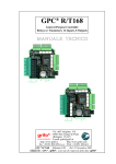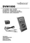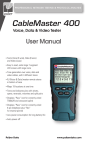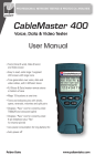
1
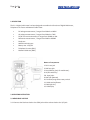
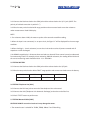
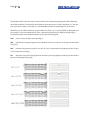
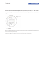
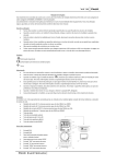
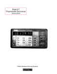
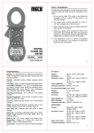
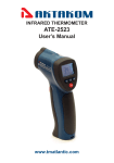
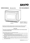
Network Multimeter
AM-1016
User’s Manual
www.tmatlantic.com
3DJH
RI
:::70$7/$17,&&20
1. SAFETY INFORMATION
WARNING
To ensure safe operation, and in order to exploit to the full
functionality of the meter, please follow the directions in this
section carefully.
This multimeter has been designed according to IEC-1010 concerning electronic measuring instruments
with an over voltage category CAT II 1000V, CAT III 600V and pollution2.
With proper use and care, the digital multimeter will give you years of satisfactory service.
Follow all safety and operating instructions to ensure that the meter is used safely and is kept in good
operating condition.
1.1 PRELIMINARY
1.1.1 When using the meter, the user must observe all normal safety rules concerning:
•
•
Protection against the danger of electrical attack
Protection of the meter against misuse
1.1.2 When the meter is delivered, check if it has been damaged in transit.
1.1.3 When harsh preservation or shipping conditions caused, inspect and confirm this meter without
delay.
1.1.4 Test leads must be in good condition. Before using, verify that the insulation on test leads is not
damaged and/or the leads wire is not exposed.
1.1.5 Full compliance with safety standards can be guaranteed only id used with test leads supplied. If
necessary, they must be replaced with the same model or the same class.
1.2 DURING USE
1.2.1 Never exceed the protection limit values indicated in specifications for each range of
measurement.
1.2.2 When the meter is linked to measurement circuit, do not touch unused terminals.
3DJH
RI
:::70$7/$17,&&20
1.2.3 When the value scale to be measured is unknown beforehand, set the range selector at the highest
position.
1.2.4 Before rotating the range selector to change functions, disconnect test leads from the circuit under
test.
1.2.5 When carrying out measurements on TV or switching power circuits, always remember that there
may be high amplitude voltages pulses at test points which can damage the meter.
1.2.6 Never perform resistance measurements on live circuits.
1.2.7 Always be careful when working with voltages above 60V dc or 30V ac rms. Keep fingers behind
the probe barriers while measuring.
1.3 SYMBOLS
Important safety information, refer to the operating manual.
European Union Directive. Earth Ground.
1.4 MAINTENANCE
1.4.1 Please do not attempt to adjust or repair the meter by removing the rear case while voltage is
being applied. A technician who fully understands danger involved should only carry out such actions.
1.4.2 Before opening the case of the meter, always disconnect test leads from all sources of electric
current.
1.4.3 To avoid the wrong reading causing electricity attack, when the meter displays
change the battery.
, you must
1.4.4 For continue protection against fire, replace fuse only with the specified voltage and current
ratings: F 200mAl250V (quick acting).
1.4.5 Do not use abrasives or solvents on the meter; use a damp cloth and mild detergent only.
1.4.6 ALWAYS set the power switch to the OFF position when the meter is not in use.
1.4.7 If the meter is to be stored for a long period of time, the batteries should be removed to prevent
damage to the unit.
3DJH
RI
:::70$7/$17,&&20
2. DESCRIPTION
The 3 in 1 digital multi-tester has been designed to combine the functions of Digital Multimeter,
Telephone Line Tester and Network Cable Tester.
•
•
•
•
•
•
•
•
•
DC voltage measurement, 5 ranges from 200mV to 1000V
AC voltage measurement, 5 ranges from 200mV to 700V
DC/AC current measurement, 5 ranges from 200MA to 10A
Resistance measurement, 7 ranges from 200Ω to 200MΩ
Diode test
Audible continuity test
Battery test: 1.5/6/9V
Telephone Line test (RJ11)
Network Cable test (RJ45)
Names of components
1. RJ 11 test jack.
2. RJ45 test jack.
3. Data hold key (only for multimeter).
4. AC/DC switch key.
5-8. input jacks.
9. RJ45 jack (Remote)
10. Function/range select rotary switch.
11. Cable test key/Resent.
12. Back light key.
13. LCD display
3. OPERATING INSTRUCTION
3.1 MEASURING VOLTAGE
3.1.1 Connect the black test lead to the COM jack and the red test lead to the V/Ω jack.
3DJH
RI
:::70$7/$17,&&20
3.1.2 Set the rotary switch at the desired "V' range position and connect test leads across the source or
load under measurement.
3.1.3 Put down the "AC/DC" when measuring the voltage. Meter will be transformed between DC and
AC range.
3.1.4 If you need data hold when measuring, you can put on "HOLD", it will hold the reading; if you put
the button again, data hold will not continue.
3.1.5 When only the figure"1 "is displayed, it indicates over range situation and the higher range has to
be selected.
3.2 MEASURING CURRENT
3.2.1 Connect the black test lead to the COM jack and the red test lead to the A jack for a maximum of
200mA. For a maximum of 10A, move the red lead to the 10A jack.
3.2.2 Set the rotary switch at desired "A" range position and connects test leads in series with the load
under measurement.
3.2.3 Put down the "AC/DC" when measuring the current. Meter will be transformed between DC and
AC range.
3.2.4 If you need data hold when measuring, you can put on "HOLD", it will hold the reading; if you put
the button again, data hold will not continue.
3.2.5 When only the figure"1"is displayed, it indicates over range situation and the higher range has to
be selected.
3.3 TESTING DIODE/CONTINUITY
3.3.1 Connect the black test lead to the COM jack and the red test lead to the V/ Ω jack. (NOTE: The
polarity of red lead connection is positive" + ")
3.3.2 Set the rotary switch at
position and connect the red lead to the anode, the black lead to the
cathode of the diode under testing. The meter will show the approx. Forward voltage drop of the diode.
If the lead connection is reversed, only figure"1"will be displayed. If continuity exists (i.e., resistance less
than about 70Ω), built - in buzzer will sound.
3.4 MEASURING RESISTANCE
3DJH
RI
:::70$7/$17,&&20
3.4.1 Connect the black test lead to the COM jack and the red test lead to the V/ Ω. jack. (NOTE: The
polarity of red lead connection is positive"+")
3.4.2 Set the rotary switch at desired Ω range position and connect test leads across the resistance
under measurement. Read LCD display.
NOTE:
1. For resistance above 1 MΩ, the meter may take a few seconds to stabilize reading.
2. When the input is not connected, i.e. at open circuit, the figure '1” will be displayed for the overrange
condition.
3. When checking in - circuit resistance, be sure the circuit under test has all power removed and all
capacitors are full discharged.
4. At 200MΩ range display is 10 counts when test leads are shorted. These counts have to be subtracted
from measuring results. For example, when measuring 100M Ω resistance, the reading will be 101.0 and
the correct measuring result should be 101.0 - 1.0 = 100.0 MΩ
3.5 TESTING BATTERY
3.5.1 Connect the black test lead to the COM jack and the red test lead to the V/Ω jack.
3.5.2 Set the rotary switch at the desired "BAT" range position and connect test leads across the battery.
Position
1.5 v
6v
9v
Load
27Ω
68Ω
100Ω
3.6 TESTING Telephone Line (RJ11)
3.6.1 Connect the RJ11 test jack to one end of the telephone line to be tested.
3.6.2 Connect the UAX (Telephone Unit Automatic Exchange) to the other end of the line.
3.6.3 Push "TEST”' button to perform test.
3.7 TESTING Network Cable (RJ45)
CAUTION! DO NOT use on the circuits as it may damage the tester.
• The network tester is suitable for T168A, T568B, 10Base-T and Token Ring.
3DJH
RI
:::70$7/$17,&&20
The Network Cable Tester will check a fault condition in the above descending order before detecting
other fault conditions. The detection and indication of the presence of a fault is handled on a. "one-pertest" basis. Once a fault is corrected, it is recommended the cable be tested again for other faults.
OPEN There is no "OPEN" indication. A typical cable may have 2, 3, or 4 pairs. OPENS are displayed as an
unlit symbol. The user will determine if a pair is present and continuous or OPEN by comparing the
illuminated symbol to the expected number of pairs that should be good.
SHO.
A short circuit condition exists (see Fig.1).
MIS. Indicates the improper assignment of individual wire pairs to pins for the wiring schemes tested
(see Fig.2).
REV. Reverse wiring means the pin for one wire in a pair is connected to the opposite pin for the pair
in the remote jack (see Fig.3).
SPL.
Split pairs occur when the tip (positive conductor) and ring (negative conductor) of two twisted
pairs are interchanged (see Fig.4).
3DJH
RI
:::70$7/$17,&&20
3.7.1 Connect the RJ45 test jack to one end of the cable to be tested.
3.7.2 Connect the remote unit to the other end of the cable.
3.7.3 Push TEST button to perform test. Example: The Cable Fault is a SHORT on Pair 1-2 and Pair 3-6,
the LCD status will be as follows:
Pair 1-2, Pair 3-6, Pair 4-5, Pair 7-8, SHIE and SHO will display at the same time.
3.7.4 Push TEST button again, Pair 1-2, Pair 3-6 and SHO will display. Continue to Push TEST button, the
next pairs will display.
4. SPECIFICATIONS
Accuracy is specified for a period one year after calibration and at 18 ⁰C to 28 ⁰C (64⁰F to 82 ⁰F) with
relative humidity to 80 %.
4.1 GENERAL
MAXIMUM VOLTAGE
FUSE PROTECTION
POWER SUPPLY
OPERATING TEMPERATURE
STORAGE TEMPERATURE
DIMENSION
WEIGHT
1000V DC or 700V AC
mA: F 200mA/250V 10A: no
9V battery, NEDA 1604 or 6F22
0 ⁰C to 40 ⁰C (32 ⁰F to 104 ⁰F)
-10 ⁰C to 50 ⁰C (14 ⁰F to 122 ⁰F)
185 x 85 x 44 mm
360 g
4.2 VOLTAGE
DC VOLTAGE
Range
Resolution
200m V
2V
0.1mV
1mV
20V
200V
10mV
100mV
1000V
1V
Accuracy
± 0.8 % of rdg ± 2 digits
± 1.2 % of rdg ± 3 digits
3DJH
RI
AC VOLTAGE
Range
Resolution
Accuracy
200mV
0.1mV
+ 1.2 % of rdg + 3digits
2V
1mV
20V
10mV
200V
100mV
700V
1V
± 0.8 % of rdg ±3 digits
+ 1.2 % of rdg + 5 digits
Input Impedance: 10MΩ
Frequency Range: 40Hz to 400Hz (for AC)
Response: Average, calibrated in rms of sine wave
4.3 CURRENT
DC CURRENT
Range
Resolution
Accuracy
200 μA
0.1 μA
2mA
1 μA
20m A
10 μA
200m A
100 μA
±1.5 % of rdg ± 2digits
10A
10mA
±2.0 % of rdg ± 5 digits
±0.8 % of rdg ± 3digits
AC CURRENT
Range
Resolution
Accuracy
200 μA
0.1 μA
+2.0 % of rdg ± 3 digits
2mA
1 μA
20mA
10 μA
200mA
100 μA
±1.8 % of rdg ± 3 digits
10A
10mA
±3.0 % of rdg ± 5digits
±1.0 % of rdg ± 3 digits
:::70$7/$17,&&20
3DJH
RI
:::70$7/$17,&&20
Overload Protection: F 200Ma/250V fuse for 200μA to 200mA ranges
Frequency Range: 40Hz to 400Hz (for AC)
Response: Average, Calibrated in rms of sine wave
4.4 RESISTANCE
Range
Resolution
Accuracy
200Ω
2KΩ
20KΩ
200KΩ
2MΩ
20MΩ
200MΩ
0.1Ω
1Ω
10Ω
100Ω
1KΩ
10KΩ
100KΩ
± 0.8 % of rdg ± 3 digits
± 0.8 % of rdg ± 2 digit
± 0.8 % of rdg ± 2 digit
± 0.8 % of rdg ± 2 digit
± 0.8 % of rdg ± 2 digit
± 1.0 % of rdg ± 2 digit
± 5.0 % of (rdg-10digits)
± 10 digits
Maximum Open Circuit Voltage: 700mV (3V for200MΩ range).
Note: On 200MQ range, if short input, display will read 1 MQ, this 1 MQ should be subtracted from
measurement results.
Overload Protection: 250V dc or 250V ac rms
4.5 DIODE/CONTINUTY
Range
Diode
Continuit
I Description
Shows the approximate forward
voltage drop
Built - in buzzer will sound, if the
resistance under test is less than
about 70Ω
Overload Protection: 250V dc or 250V ac rms
5. BATTERY & FUSE REPLACEMENT
If the sign"
"appears on the LCD display, it indicates that battery should be replaced.
Remove screws on the back cover and open the case (see the right photo). Replace the exhausted
battery with a new one.
3DJH
RI
:::70$7/$17,&&20
Fuse rarely need replacement and blow almost always as a result of the operator's error. Open the case
as mentioned above, and then take the PCB out from the front cover. Replace the blown fuse with same
ratings.
WARNING
Before attempting to open the case, be sure that test leads have been disconnected from measurement
circuits to avoid electric shock hazard.
For protection against fire, replace fuse only with specified ratings: F 200mA/250V