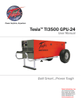
1
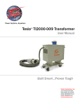
Power Anytime, Anywhere Tesla™ TI2000-308 3 kW Inverter System Pure Sine Wave Inverter User Manual Built Smart...Proven Tough Tesla™ Industries, Inc. 101 Centerpoint Blvd. New Castle, DE 19720 (302) 324-8910 Phone (302) 324-8912 Fax www.teslaind.com NOTE: All users must read this entire manual prior to operating the TI2000-308 3 kW Inverter System. The TI2000-308 3 kW Inverter System is a maintenance-free and sealed unit. No repairs are authorized. Warranty will be voided if unit is tampered with in any way, or if unauthorized repairs are made. For technical support please contact: TESLA™ INDUSTRIES INCORPORATED 101 CENTERPOINT BLVD. CENTERPOINT INDUSTRIAL PARK NEW CASTLE, DELAWARE 19720 PHONE: (302) 324-8910 FAX: (302) 324-8912 WEBSITE: www.teslaind.com EMAIL: [email protected] CAUTION Shock Hazard Potential Improper use or failure to follow instructions in this user manual can result in unit damage and/or injury or death by electrical shock. Any attempts to open or examine the inside of the TI2000-308 3 kW Inverter System via a tool or device (borescope, probe, etc.) can result in unit failure and/or injury by electrical shock. This Inverter System is maintenance free and should not be opened or disassembled for any reason. Always protect the unit from short circuit. Shipping Hazards: The TI2000-308 3 kW Inverter System does not pose a shipping hazard. No part of this manual may be reproduced or transmitted in any form or by any means, electronic or mechanical, including photocopying, recording, or any information storage and retrieval system, without prior written permission from Tesla™ Industries, Inc. Copyright © 2015 by Tesla™ Industries, Incorporated. All rights reserved. 11-13-15 Table of Contents Section 1 – Safety Review 1.1 – Safety Notices 1.2 – Symbols 1.3 – Hazards 1.4 – Important Safety Precautions 1.5 – Extreme Environments 1 1 2 2 2 2 Section 2 – Product Overview 3 2.1 – Introduction 3 2.2 – Indication of Terms: Shall, Should, May 3 2.3 - Front Panel Overview 4 2.4 – General Specifications 5 2.5 – Physical Dimensions 6-7 2.6 – Airflow Ports 7 2.7 – Operating Positions 7 2.8 – Active Output Circuit Breaker 8 2.9 – AC Output Cord 8 2.10 – AC Output Power Status LED Indicator 9 2.11 – 24 Vdc Input Connector 9 2.12 – DC Input Circuit Breaker 10 2.13 – DC Input Voltage LED Indicator 10 2.14 – DC NATO Cable Assembly 11 2.15 – Alarm LED Indicators 11 2.16 – Inverter Power Switch11 Section 3 – Pre-Operation 3.1 – General 3.2 – Operating Limits and Restrictions 3.3 – Performance 3.4 – Temperature Specifications 3.5 – Environmental 12 12 12 12 13 13 TI2000-308 3kW Inverter System 3.6 – Pre-Operation 3.7 – 20-30 Vdc Input Power 3.8 – Alarm LED Indications 14 11-15 16-17 Section 4 – Post-Operation 4.1 – General 4.2 – After Use 19 19 19 Section 5 – Unit Care and Maintenance 5.1 – Unit Care 5.2 – Unit Servicing 5.3 – Transporting Unit 5.4 – Packaging and Shipping 19 19 20 20 20 Section 6 – Troubleshooting and FAQ 6.1 - Frequently Asked Questions 6.2 - Basic Unit Troubleshooting 21 21 22 Section 8 – Optional Accessories 8.1 – Replacement Contacts and Tools 8.2 – Transportation Case 23 23 23 Repair Request Form 24 TI2000-308 3kW Inverter System Abbreviations and Symbols Abbreviations that may be used within the text, headings and titles of this manual. LIST OF ABBREVIATIONS Abbreviation ac AFT AWG amp or A cont °C °F dc EFF ft FWD GPU Hr Hz kg kHz kW LED max MΩ min MPU NEMA Ω PF PFC rms THD TMDE UAV Vac Vdc W Definition Alternating Current Airflow Technology American Wire Gauge Ampere Continuous Degree Celsius Degree Fahrenheit Direct Current Efficiency Feet Forward Ground Power Unit Hour Hertz Kilograms Kilohertz Kilowatts Light Emitting Diode Maximum megaohm Minimum Micro Power Unit National Electrical Manufacturers Association ohm power factor power factor correction root-mean-square Total Harmonic Distortion Test, Measurement, & Diagnostic Equipment Unmanned aerial vehicle Volts, Alternating Current Volts, Direct Current watts TI2000-308 3kW Inverter System on 1Section – Safety1Review – Safety Review Safety Notices 1.1 - Safety Notices otices appear Safety notices throughout appear this throughout manual to alert this manual the usertotoalert important the user information to important regarding information properregarding proper on, operation, installation, maintenance operation, and maintenance storage of the andunit. storage These of the notices, unit. as These illustrated notices, below, as illustrated contain abelow, contain a d that indicates key wordthe that level indicates of hazard theand levelaof triangular hazard and iconathat triangular indicates iconthe that specifi indicates c typethe of hazard. specific type of hazard. Indicates a condition, Indicates operating a condition, procedure operating or practice, procedure which or ifpractice, not which if not WARNING ! WARNING adhered to could adhered result intoserious could result injuryinorserious death. injury or death. CAUTION! NOTE ! Indicates a condition Indicates or operating a condition procedure, or operating which procedure, if not strictly which if not strictly CAUTION adhered to could adhered result intodamage could result or destruction in damageoforequipment. destruction of equipment. Indicates a condition, Indicates operating a condition, procedure operating or practice, procedure which or is practice, which is NOTE essential to highlight. essential to highlight. ymbols1.2 - Symbols wing symbols The following will appear symbols within willthe appear warning within triangles the warning to alerttriangles the usertotoalert the specifi the user c type to the of danger specific type of danger d. or hazard. ! ! ral WarningGeneral Warning Electrical HazardElectrical Hazard Explosion Hazard Explosion Hazard Fire Hazard Fire Hazard Battery WarningBattery Warning Guard from Moisture Guard from Moisture Figure 1.2.1 – Different Figure 1.2.1 types– of Different hazard types and caution of hazard symbols and caution symbols TI2000-308 3kW Inverter System 1 Safety Review 1 1.3 – Hazards WARNING Shock Hazard Potential Severe injury or death from electrical shock will occur if either the user or the TI2000-308 3 kW Inverter System is wet while operating the unit. Be sure to disconnect power from the AC Output Cable if the TI2000-308 3 kW Inverter System has come into contact with water. If the AC Output Circuit Breaker has tripped due to water infiltration, DO NOT try to reset circuit breaker until Inverter System has dried completely. WARNING Shock Hazard Potential Severe injury or death from electrical shock can occur when damp electrical plugs are connected to the TI2000-308 3 kW Inverter System. Make sure the electrical outlet is switched off before making any connections. Failure to use proper grounding can cause potential shock hazard! CAUTION Unit Damage Potential The unit will be damaged if unapproved dc power is applied. This Unit operates from 20-30 Vdc @ 250 Amps Max. CAUTION Unit Damage Potential Turn off dc input power before connecting or disconnecting dc input power. Failure to turn off dc power could cause voltage spikes that can permanently damage the Unit. 1.4 – Important Safety Precautions WARNING Fire/Explosion Hazard Potential Severe injury or death from fire or explosion can occur if electrical sparks are produced near fuel vapors. DO NOT CONNECT ac output power from Inverter System while operating or handling any type of fuel. 1.5 – Extreme Environments CAUTION Unit Damage Potential The TI2000-308 3 kW Inverter System is equipped with a temperature sensor that automatically disables Inverter functions when the internal temperature reaches above 150°F (65°C). This protects the unit from overheating and damage. If the unit shuts down, move the unit into a cooler climate such as shade or air conditioning when possible. 2 TI2000-308 3kW Inverter System Section 2 – Product Overview 2.1 – Introduction Thank you and congratulations on the purchase of your new TI2000-308 3 kW Inverter System. This System is one of Tesla™ Industries latest advancements in power technology development. The TI2000308 is a Pure Sine Wave Inverter System. The TI2000-308 3 kW Inverter System was designed to provide 120/240 Vac @ 12.5 amps of pure regulated AC power. This manual contains the complete operating instructions and procedures for the TI2000-308 3 kW Inverter System that the end user will need to safely and efficiently operate this system. Figure 2.1.1 – TI2000-308 3 kW Inverter System (pictured with optional case) 2.2 – Indication of Terms: Shall, Should and May Within this technical manual the word “shall” is used to indicate a mandatory requirement for proper operation and warranty purposes. The word “should” is used to indicate a non-mandatory but preferred method of accomplishment. The word “may” is used to indicate an acceptable method of accomplishment. TI2000-308 3kW Inverter System 3 2 Product Overview 2.3 – Front Panel Overview 1 2 9 8 5 7 6 3 4 1. 15’ Hardwired DC NATO Cable Assembly – Provides an Input of 20-30 Vdc @ 250 Amps Max. 5. Alarm LED Indicators - Alerts the user of overvoltages, under-voltages, over-temperatures, and overloads. 2. Inverter Power Switch – Acts as on “On/ Off” Switch for the TI2000-308 3 kW Inverter System. 6. Output Power Status Indicator – Displays the ac current load. 3. 25’ Hardwired AC Line Cord – Provides an Output of 240 Vac 60 Hz. @ 12.5 Amps / 120 Vac 60 Hz. @ 25 Amps 4. AC Output Circuit Breaker - Acts as on “On/ Off” Switch for the AC Output. 4 7. Input Voltage Indicator – Displays Input Voltage from a range of 20-30 Vdc. 8. 24 Vdc Input Receptacle – Provides an Input of 20-30 Vdc @ 250 Amps Max. 9. DC Input Circuit Breaker - Acts as on “On/ Off” Switch for the dc Input. TI2000-308 3kW Inverter System Product Overview 2 2.4 – General Specifications Electrical AC Output Power: • Provides Single Phase 120/240 Vac (+/- 5%) , 60 Hz • 12.5 Amps @ 240 Vac 60 Hz • 25 Amps @ 120 Vac 60 Hz DC Input Power: • 250 Amps Max • 20-30 Vdc 3 kW AC Inverter: • 120 Vac 60Hz Pure Sine Wave (+/- .05%) • 25 amps surge • 12.5 amps continuous power • <2% THD • Minimum Unit Efficiency: 85% Size of TI2000-308: • 36.33” long x 11.57” wide x 18.40” high • 922.7 mm x 293.9 mm x 467.4 mm Size of optional TI7000-223 Transportation Case: • 48.52” long x 23.99” wide x 15.71” high • 1232.3 mm x 609.4 mm x 399.0 mm Weight: • 106.5 lbs (48.3 kg) • 169.5 lbs (76.8 kg) with optional case Operating Temperature: • -20° C to +65° C • -4° F to +150° F Storage Temperature: • -40° C to +65° C • -40° F to +150° F TI2000-308 3kW Inverter System 5 2 Product Overview 2.5 – Physical Dimensions 11.57 [293.9] 18.40 [467.4] 14.03 [356.2] 7.83 [198.8] 30.82 [782.9] 36.33 [922.7] Figure 2.5.1 – TI2000-308 3 kW Inverter System physical dimensions 6 TI2000-308 3kW Inverter System Product Overview 48.52 [1232.3] 2 15.71 [399.0] 23.99 [609.4] Figure 2.5.2 – TI7000-223 Transportation Case Dimensions 2.6 – Airflow Ports Damage may occur if the TI2000-308 3 kW Inverter System’s air intake or outlet ports are obstructed. Ensure that ports are clear at all times. CAUTION When the TI2000-308 3 kW Inverter System is plugged into 20-30 Vdc input power, the internal cooling system will efficiently regulate unit temperature regardless of load. At room temperature (+77°F) the exhaust air will not exceed the ambient temperature by more than 5°F. In more extreme temperatures (greater than 90°F) the exhaust air will not exceed the ambient temperature by more than 10°F (See Figure 2.6.1). Figure 2.6.1 – Air intake, exhaust ports and internal air circulation 2.7– Operating Positions The TI2000-308 3 kW Inverter System is operated in horizontal position as shown. Make sure that the airflow is not obstructed from air intake and outlet. TI2000-308 3kW Inverter System 7 2 Product Overview 2.8 – AC Output Circuit Breaker This System is equipped with a 12.5 Amp AC Output Circuit Breaker (Shown in Figure 2.8.1) that acts as an “On/Off” switch for the AC Output. When the AC Output Circuit Breaker is active the LED will illuminate. Figure 2.8.1 - AC Output Circuit Breaker (outlined in blue) 2.9 – AC Output Cord The AC Output Cord (See Figure 2.9.1) is 25’ in length. It has a Hardwired Plug (2713 / Tesla™ part # TI250000-044). Contact Tesla™ Industries for additional plug configurations. Figure 2.9.1 Hardwired AC Output Cord with Plug (Plug # 2713) 8 TI2000-308 3kW Inverter System Product Overview 2 2.10 – Output Power Status LED Indicator The Output Power Status LED Indicator (See Figure 2.10.1) provides a way for the user to visually see the applied ac load that the TI2000-308 3 kW Inverter System is providing. This lets the operator know how much power that the equipment is drawing. Figure 2.10.1 - Output Power Status Indicator location (outlined in blue) 100% Output Max. Load 50% Output Load Less Than 20% Output Load 2.11 – 24 Vdc Input Connector The 24 Vdc Input Connector will support an Input Voltage range of 20-30 Vdc. This is a secondary connector. It is to be used if the 15’ DC NATO Cable Assembly is damaged. When the Input Connector is not in use, cover the receptacle with the protective cover (see Figure 2.11.1). This will protect the Input Connector from dust and foreign matter. Figure 2.11.1 24 Vdc Input Connector TI2000-308 3kW Inverter System 9 2 Product Overview 2.12 – DC Input Circuit Breaker This System is equipped with a 100 amp DC Input Circuit Breaker (Shown in Figure 2.12.1) that acts as an “On/Off” switch for the dc input. When the DC Input Circuit Breaker is active the LED will illuminate. ! CAUTION Turn off dc input power before connecting or disconnecting dc input power. Failure to turn off dc power may cause voltage spikes that can permanently damage the unit. Figure 2.12.1 - DC Input Circuit Breaker (outlined in blue) 2.13 – DC Input Voltage LED Indicator The DC Input Voltage LED Indicator provides a way for the user to visually see the voltage that the TI2000308 3 kW Inverter System is receiving. Figure 2.13.1 - Input Voltage Status Indicator location (outlined in blue) Input Voltage at 24 VDC 10 Input Voltage at 30 VDC TI2000-308 3kW Inverter System Product Overview 2 2.14 – DC NATO Cable Assembly The DC NATO Cable Assembly is 15’ in length. It has been Hardwired to the TI2000-308 3 kW Inverter System. ! NOTE Do not connect the Hardwired DC NATO Cable Assembly to the 24 Vdc Input Connector. Figure 2.14.2 Hardwired DC NATO Cable Assembly 2.15 – Alarm LED Indicators The Alarm LED Indicators alert the user of over-voltages (dc), under-voltages (dc), over-temperatures, and overloads (ac). When a problem occurs the proper LED will illuminate and an audible alert tone will sound and the Inverter Power Switch will trip, shutting off the Inverter. See Section 3.8 for explanations. Figure 2.15.1 - Alarm LED Indicator location (outlined in blue) 2.16 – Inverter Power Switch The Inverter Power Switch acts as an “On/Off” switch for the Inverter System. When switched to the “ON” position the Output will provide 120/240 Vac at 12.5 A, 60 Hz. Figure 2.16.1 - Inverter Power Switch location (outlined in blue) TI2000-308 3kW Inverter System 11 Section 3 – Operation Procedures This section deals with normal procedures, and includes all steps necessary to ensure safe and efficient operation of the TI2000-308 3 kW Inverter System. ! NOTE The ambient temperature may cause the unit’s protective “over-temperature” sensors to shut down the Inverter functions until the unit cools to normal operating temperatures. If the unit shuts itself down, get the unit into a cooler environment such as shade or air conditioning (if possible). Perform a full function check prior to continued use once the unit is allowed to cool. For continued use in extremely hot environments, it is advised to send the unit back to Tesla™ for recalibration for use in these environments. 3.1 – General Correct operation of the TI2000-308 3 kW Inverter System includes both pre-use and operational checks of the unit. Knowledge of the operating limits, restrictions, performance, unit capabilities and functions is fundamental to correct and safe operation. The operator shall ensure compliance with the instructions in this manual that affect operational safety and the warranty of the unit. 3.2 – Operating Limits and Restrictions The minimum, maximum and normal operating ranges result from careful engineering and evaluation of test data. These limitations must be adhered to during all phases of operation. 3.3 – Performance Refer to Section 7, PERFORMANCE DATA to determine the capability of the TI2000-308 3 kW Inverter System. Consideration must be given to changes in performance resulting from variations in ambient temperature and mode of operation. 3.4 – Temperature Specifications Cold/Hot Soaked Temperature The ambient temperature that a unit is exposed to for one (1) hour or more establishes the unit’s cold/hot soaked stabilization temperature. If the unit’s cold/hot soaked temperature is outside the normal operating temperature range, the unit must be stabilized prior to operation. For COLD SOAKED temperature 120% Ambient Percentage of Temperature Cell Capacity stabilization, the unit must be +40°C (+104°F) 110% ±5% placed in an environment with a 100% +25°C (+77°F) 100% ±5% temperature above +10°C (+41°F) +0°C (+32°F) 80% ±5% -20°C (-4°F) 65% ±10% for 3 hours or a temperature above -40°C (-40°F) 50% ±10% 80% +20°C (+68°F) for 2 hours. For HOT SOAKED temperature stabilization, the unit must be placed in an 60% environment with a temperature below +38°C (+100°F) for 1 hour. 40% +40°C +25°C +0°C -20°C -40°C Figure 3.4.1 Output power capability versus ambient temperature Figure-3.6.1 – Output power capability versus ambient temperature 12 TI2000-308 3kW Inverter System +40°C +25°C +0°C -20°C -40°C Figure 3.6.1 – Output power capability versus ambient temperature Operating Procedures 3 Hot Soaked or Cold Soaked Definition Simple terms: When a material is exposed to a change in temperature, its temperature will also change. Some material changes temperature quickly, others slowly. If the ambient temperature changes and is then held constant, the materials temperature will also change until its temperature stabilizes. Once the material temperature has stabilized, it is considered “soaked”. Example: A unit is moved from the cool shade into the hot sun. That unit’s temperature will increase until it stabilizes. Once stabilized, the unit would be considered “hot soaked”. ! NOTE The unit’s temperature switch automatically disables ac power functions when the internal temperature is above 150°F (65°C). This protects the unit from overheating and damage. If the unit shuts down, move the unit into a cooler climate, such as shade or air conditioning when possible. Perform a full function test prior to use after the unit has been allowed to cool. 3.5 – Environmental WARNING Shock Hazard Potential Operating any electrical equipment in the presence of moisture creates possible safety hazards and/or potential for equipment damage. Every effort has been made, within the scope of existing technology to prevent foreseeable safety hazards and make the TI2000-308 3 kW Inverter System moisture resistant to prevent damage or failure. If the TI2000-308 3 kW Inverter System is exposed to moisture, preventive measures and precautions shall be taken to: A. Prevent accumulation of moisture on ac and dc connectors/receptacles B. Minimize moisture entering forward inlet and AFT outlet cooling fan vent ports Unit inlet and outlet vent ports shall be covered from exposure. Unit shall be kept horizontal. TI2000-308 3kW Inverter System 13 3 Operating Procedures 3.6 – Pre-Operation 1. 2. 3. 4. Be sure to check that all input and output cables are not damaged. (See Section 5.1) Check unit carefully for any evidence of damage. (See Section 5.1) Make sure that airflow is not obstructed from air intake and outlet. (See Section 2.6) Check that all connections are secure and free from water. Figure 3.6.1 - TI2000-308 3 kW Inverter System 3.7 – 20-30 Vdc Input Power Connecting DC Power Cable from Inverter System to Vehicle ! 1. 2. 3. 4. 5. 6. 7. CAUTION Turn off DC Input Power before connecting or disconnecting DC Input Power. Failure to turn off DC Power could cause voltage spikes that can permanently damage the Unit. Place the DC Input Circuit Breaker to the OFF position. The Vehicle must be turned OFF (shut down). Plug NATO Adaptor into the NATO Connector on the Vehicle. Start the vehicle and allow it to warm up to operating temperature. Place DC Input Circuit Breaker to the ON position. Turn ON Inverter Power Switch. Turn ON AC Output Circuit Breaker. Figure 3.7.1 Attaching DC Power Cable to ground vehicle 14 TI2000-308 3kW Inverter System Operating Procedures 3 Disconnecting DC Power from Vehicle 1. 2. 3. 4. 5. Turn OFF AC Output Circuit Breaker. Turn OFF Inverter Power Switch. Turn OFF DC Input Circuit Breaker. Shut down Vehicle. Disconnect the DC NATO Plug from the NATO Connector on the Vehicle. Connecting DC NATO Plug to DC NATO Connector on the Front Panel of the Inverter System ! CAUTION ! NOTE 1. 2. 3. 4. 5. 6. 7. Turn off dc input power before connecting or disconnecting dc input power. Failure to turn off dc power could cause voltage spikes that can permanently damage the unit. Do not connect the Hardwired DC NATO Cable Assembly to the 24 Vdc Input Connector. Place the DC Input Circuit Breaker to the OFF position. Make sure dc ppower source is turned OFF. Connect NATO Cable from power source to Inverter. Turn ON dc power source. Place DC Input Circuit Breaker to the ON position. Turn ON Inverter Power Switch. Turn ON AC Output Circuit Breaker. Disconnecting DC Cable from the TI2000-308 3 kW Inverter System 1. 2. 3. 4. 5. Turn OFF AC Output Circuit Breaker. Turn OFF Inverter Power Switch. Turn OFF DC Input Circuit Breaker. Shut down dc power source. Disconnect the NATO Cable. TI2000-308 3kW Inverter System 15 3 Operating Procedures 3.8 – Alarm LED and Tone Indications Over-Voltage DC The Over-Voltage LED will illuminate if the operational voltage for the Inverter System exceeds the preset value of 30 Vdc Input power. This Alarm will only apply to the dc functions of The TI2000-308. Under-Voltage DC The Under-Voltage LED will illuminate if the operational voltage for the Inverter System has dropped below the preset value of 20 Vdc Input power. This Alarm will only apply to the dc functions of The TI2000-308. Over-Temperature The Over-Temperature LED will illuminate if the Inverter System is operating at a temperature exceeding the preset value of 150º F ( 65.5º C). Overload The Overload LED will illuminate if the ac voltage or ac current load of the Inverter System has exceeded 240 volts or 12.5 Amps. This Alarm will only apply to the ac functions of The TI2000-308. What to do if the Over-Voltage LED Illuminates 1. Turn OFF AC Output Circuit Breaker. 2. Turn OFF Inverter Power Switch. 3. Turn OFF DC Input Circuit Breaker. 4. Shut down DC Power Source. 5. Check the DC Input Power source. 6. Turn DC Input Circuit Breaker ON then OFF again. 7. Check DC Input Power Cable ensuring it is connected correctly and fully seated. 8. Check DC Input Connectors for foreign objects. 9. Check Positive and Negative Power Connectors for serviceability. 10.Reconnect all power cables to the Unit. 11.Turn ON DC Input Circuit Breaker. 12.Turn ON Inverter Power Switch. 13.Turn ON AC Output Circuit Breaker. 14.If the Over-Voltage LED illuminates again, shut the TI2000-308 3 kW Inverter System down and contact Tesla™ Industries. What to do if the Under-Voltage LED Illuminates 1. Turn OFF AC Output Circuit Breaker. 2. Turn OFF Inverter Power Switch. 3. Turn OFF DC Input Circuit Breaker. (Continued on next page) 16 TI2000-308 3kW Inverter System Operating Procedures 3 What to do if the Under-Voltage LED Illuminates (Continued) 4. Shut down DC Power source. 5. Check the DC Input Power source. 6. Turn DC Input Circuit Breaker ON then OFF again. 7. Check DC Input Power Cables ensuring they are connected correctly and fully seated. 8. Check DC Input Connectors for foreign objects. 9. Check Positive and Negative Power Connectors for serviceability. 10.Reconnect all Power Cables to the TI2000-308 3 kW Inverter System. 11.Turn ON DC Input Circuit Breaker. 12.Turn ON Inverter Power Switch. 13.Turn ON AC Output Circuit Breaker. 14.If the Over-Voltage LED illuminates again, shut the TI2000-308 3 kW Inverter System down and contact Tesla™ Industries. What to do if the Over-Temperature LED Illuminates 1. 2. 3. 4. 5. 6. 7. 8. 9. Turn OFF AC Output Circuit Breaker. Turn OFF Inverter Power Switch. Turn OFF DC Input Circuit Breaker. Move the TI2000-308 3 kW Inverter System to a cool place for a minimum of one hour. Reconnect all Power Cables to the TI2000-308 3 kW Inverter System. Turn ON DC Input Circuit Breaker Turn ON Inverter Power Switch. Turn ON AC Output Circuit Breaker. If the Over-Temperature LED illuminates again, shut the TI2000-308 3 kW Inverter System down and contact Tesla™ Industries. What to do if the Overload LED Illuminates 1. Turn OFF AC Output Circuit Breaker. 2. Turn OFF Inverter Power Switch. 3. Turn OFF DC Input Circuit Breaker. 4. Check the AC Output Cable Connector for serviceability. 5. Check the power demands of the unit you are powering. 6. Reconnect DC Input Power to the power source. 7. Reconnect AC Output Power. 8. Turn ON DC Input Circuit Breaker 9. Turn ON Inverter Power Switch. 10.Turn ON AC Output Circuit Breaker.. 11.If the Overload LED illuminates again, shut the TI2000-308 3 kW Inverter System down and contact Tesla™ Industries. TI2000-308 3kW Inverter System 17 Section 4 – Post Operation 4.1 – General Although the TI2000-308 3 kW Inverter System has been ruggedized and made weather resistant within the scope of unit’s intended use, it is essential that good general care be taken to maintain unit in good operating condition and to maximize unit’s operational life. 4.2 – After Use Unit should be protected from environmental elements and man-made hazards. Ideally unit should be secured inside the carrying case. 18 TI2000-308 3kW Inverter System Section 5 – Unit Care and Maintenance WARNING Severe injury or death from electrical shock will occur if either the user or the TI2000-308 3 kW Inverter System is wet while operating the unit with the AC Output power connected. CAUTION Damage may occur if an unapproved or modified AC line cable or input plug is attached to the Inverter System. Do not use any type of AC voltage converter. 5.1 - Unit Care Avoid Prolonged Exposure to Extremely Damp Environments Be sure to turn off the Inverter Power Switch and disconnect dc input power and ac output power from the Inverter System if the TI2000-308 3 kW Inverter System has come into contact with water. If the AC Output Circuit Breaker or the DC Input Circuit Breaker has tripped due to water infiltration, allow the unit to dry out before attempting to reset circuit breaker. Cover the unit to prevent water seepage. If the unit is operated in extremely damp conditions, it should be stored in an environmentally controlled building when not in use. Wipe unit clean periodically with a soft cloth to remove dust, dirt, etc. Protect Cables from Damage Do not cut, crush, or drag the input or output power cables when handling the TI2000-308 3 kW Inverter System. Always inspect cables prior to use. If no damage is evident, proceed to the next step. If damage is evident, contact Tesla™ Customer Service. Figure 5.1.1 – Damaged cable TI2000-308 3kW Inverter System 19 5 Unit Care and Maintenance 5.2 – Unit Servicing The TI2000-308 3 kW Inverter System is a maintenance-free, sealed unit. No repairs outside of Tesla™ are authorized. Warranty will be voided if unit is tampered with in any way including any damage to the WARRANTY VOID stickers located on the case (see Figure 5.2.1 below). If the unit requires maintenance, please contact Tesla™ Customer Service at (302) 324-8910. A Repair Request Form can be found in the back of this manual. Figure 5.2.1 – Warranty Void stickers on the TI2000-308 3 kW Inverter System 5.3 – Transporting Unit The TI2000-308 3 kW Inverter System has four affixed handles (See Figure 5.3.1) so that it can be carried for short distances by hand. If the area of operation is further then 45 meters (150 feet) the TI2000-308 3 kW Inverter System should be transported on a vehicle inside of the TI7000-223 Transportation Case. The case has been designed to be carried by two people. It has four permanently affixed handles. The case weighs 63 lbs (28.57 kg). Figure 5.3.1 Affixed Carrying Handles Figure 5.3.2 TI7000-223 Transportation Case 5.4 – Packaging and Shipping When returning the Inverter System, please ensure that it is properly packaged. The recommended method for transport is in it’s original Transportation Case (be sure to enclose the Repair Request Form). Return it to Tesla™ at the address listed below. Please contact Tesla™ Customer Service at (302) 324-8910 with any questions or concerns. TESLA™ INDUSTRIES, INCORPORATED 101 CENTERPOINT BLVD. CENTERPOINT INDUSTRIAL PARK NEW CASTLE, DELAWARE 19720 PHONE: (302) 324-8910 FAX: (302) 324-8912 Website: www.teslaind.com Email: [email protected] 20 TI2000-308 3kW Inverter System Section 6 – Troubleshooting and FAQ 6.1 – Frequently Asked Questions 1. Why should I buy a Tesla™ Power Inverter System? A Tesla™ Power Inverter System is an advanced piece of equipment and an ideal method of converting 20-30 dc voltage to pure usable 120/240 ac voltage. This system can be used in a tactical or non-tactical environment giving the user the needed flexibility to operate ac components (with approved connectors) like laptop computers, test measurement and diagnostic equipment, additional lighting, or any other item that requires ac voltage. This unit is man-portable, maintenance free, and can be operated from any 20-30 dc voltage power sources. Designed for military applications it is easily transported and is invaluable for times when ac power is required in a field environment. 2. How much power will my Inverter System provide? The TI2000-308 3 kW Inverter System will provide up to 12.5 amps continuous, regulated ac power at 120/240 Vac. 3. Is it waterproof? Water-resistant but not waterproof. 4. Are Tesla™ Power System’s used in shop maintenance and testing? Tesla™ systems are gaining popularity throughout maintenance facilities, instructional facilities, laboratories, manufacturing plants, aircraft hangars and many other locations. The reason is due to the precise flat line dc power, the small, portable and quiet nature of our systems and the maintenance free aspect of our Inverter Systems. We can custom tailor ground power systems to fit your individual requirements. 5. Can one person transport it? It is not recommended for one person to transport the TI2000-308 3 kW Inverter System. The system alone weighs 106.5 lbs, and when it is in it’s case it weighs 169.5 lbs. 6. How do I get my Inverter System serviced? Contact Tesla™ Customer Service at (302) 324-8910. You can also email us at [email protected]. Once we receive the unit at our facility, we will examine it. Systems that are protected under warranty will be repaired at no charge. If the warranty has expired, you will receive a quote for necessary repairs prior to work being done. Our turnaround time is 48 hours once repairs are authorized. 7. Can I make my own repairs to unit? During the warranty period, the unit can only be repaired by Tesla™ Industries for the warranty to remain in effect. Regardless, we strongly recommend allowing Tesla™ to repair any unit as we will analyze the complete system and recalibrate it. 8. What type of maintenance does the Tesla™ Inverter System require? The systems is maintenance free. Keep the vent areas clean and free of debris. Keep the unit in a protected environment when not in use (maintenance facility, shed). 9. What is included with my Tesla™ Inverter System? Customers will receive a hardwired fifteen (15’) foot DC Mechanized Cable Assembly, a hardwired twenty-five (25’) foot AC Cable Assembly and a full two year warranty. 10. Are there any HAZMAT issues or disposability problems? There are none. Contact Tesla™ if you have questions. TI2000-308 3kW Inverter System 21 6 Troubleshooting and FAQ 6.2 - Basic Unit Troubleshooting Fault Possible Cause Remedy 1. Output Power LED does not come on. A. AC Circuit Breaker has tripped. B. No dc input voltage. C. Input Power Switch has tripped. A. Reset AC Output Circuit Breaker Switch. B. Verify that dc input power is applied. C. If LEDs still do not illuminate, Please contact Tesla™ Customer Service at (302) 324-8910 2. Unit will not power from dc Input. A. DC Input cord is damaged or bad. A. Check if the Input cord is properly secured. B. Is dc Input cord fully plugged into unit. C. DC circuit breaker has been tripped. D. No DC power or under-voltage (less than 20 volts) at source. 3. Unit works then shuts down. A. Unit is overheating. B. Cooling fans and vents are obstructed or inoperable. B. Check to make sure DC Circuit Breaker is placed in the “ON” position. A. Move the unit to an area 10°-20° less ambient temperature. B. Clean and clear cooling vents, turn on unit and inspect if air is flowing through unit. If no airflow please contact Tesla. 4. Inverter Power Switch continuously trips A. Unit is overheating. B. Internal Short C. Operational voltage is above 30 Vdc. D. Operational voltage is below 20 Vdc. E. AC voltage has exceeded 240 volts. F. AC current load has exceeded 12.5 amps. A. Disconnect unit from dc input and ac output. B. Check Alarm LED and refer to Section 3.8. C. If LED still illuminates, please contact Tesla™ Customer Service at (302) 324-8910. 5. Unit does not output 240 Vac A. Unit is not connected. A. Plug unit into dc power source to maintain 240 Vac. B. Turn on Inverter Power Switch. C. Turn on AC Output Circuit Breaker. B. Inverter Power Switch is not ON. C. AC Output Circuit Breaker is not ON. 22 TI2000-308 3kW Inverter System Section 8 – Optional Accessories 8.1 – Cobra™ DC Replacement Contacts and Tools Cobra™ DC Plugs are designed to provide reliable high-power connections up to 3000 amps — even in the harshest conditions. Each plug is constructed from a rugged combination of advanced composite materials and corrosion-resistant alloys to maximize durability and connectivity. To extend the life of the Cobra Connector included with your Inverter System, replacement contacts and tools can be ordered through the Tesla™ Customer Service. TI2005-078 Cobra™ NATO Connector NSN: 6130-01-523-1270 (CL IX) TI2004-444 NATO Replacement Post For newer NATO plugs with new style post, indicated by the black tip. Replacement plug uses standard 3/4” deep well socket for installation. TI2005-121 TI2005-117 Cobra™ NATO Negative Contact Cobra™ NATO Positive Post TI2005-126 TI27000-082 Cobra™ NATO Negative Contact Insertion/Extraction Tool Cobra™ NATO Positive Contact Insertion/Extraction Tool NSN: 5999-01-525-0582 (CL IX) NSN: 5120-01-523-8761 (CL II) NSN: 5935-01-523-8914 (CL IX) NSN: 5120-01-527-7729 (CL II) 8.2 – Transportation Case The Tesla™ TI7000-223 Storage Case is designed especially to hold Tesla’s TI2000-308 3kW Inverter • Length: 48.52" (1232.3 mm) • Width: 23.99" (609.4 mm) • Height: 15.71" (399.0 mm) • Weight: 63 lbs. (28.57 kg) • Limited 2 Year Warranty Figure 8.2.1 TI7000-223 Transportation Case TI2000-308 3kW Inverter System 23 Repair Request Form Please complete the information below to ensure prompt and accurate service. Include this form with the unit you are returning. Thank you. Date of return: ________________________ Company name & ____________________________________________________________________ ____________________________________________________________________ ____________________________________________________________________ Billing address: ____________________________________________________________________ ____________________________________________________________________ ____________________________________________________________________ Contact person: ________________________________________________________________________________ Phone #: _____________________________________ Email: _______________________________________________________________________________________ Purchase Order #: Fax #: ______________________________________ ______________________________________________________________________________ Model #: ____________________________________ Serial #: ________________________________________ Model #: ____________________________________ Serial #: ________________________________________ Shipping method to Tesla™: ______________________________________________________________________ Description of shipping package: Description of problem: ________________________________________________________________ _________________________________________________________________________ _________________________________________________________________________________________________ _________________________________________________________________________________________________ _________________________________________________________________________________________________ Return to Tesla™ Industries, Inc. 101 Centerpoint Boulevard, New Castle, DE 19720 Attention: Repair Department 24 TI2000-308 3kW Inverter System Tesla™ Industries, Inc. 101 Centerpoint Blvd. New Castle, DE 19720 USA Tel: 302-324-8910 Fax: 302-324-8912 9475 Double R Blvd., Suite 2 Reno, NV 89521 Tel: 775-622-8801 Fax: 775-622-8810 www.teslaind.com