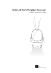
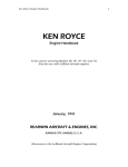
1
ACO5000 – USER MANUAL DANAHER MOTION S.A. La Pierreire 2, CH-1029 Villars-Ste-Croix Telephone +41-21-631 33 33, Telefax +41-21-636 05 09 E-mail: [email protected] www.danaher-motion.ch 21-02-05 S610-GB-0444 DANAHER MOTION S.A. Empty page Page 2 / 16 User Manual ACO5000 S610-GB-0444 DANAHER MOTION S.A. Table of content Safety instructions ..................................................................................................................................... 4 Information on the Operating Manual ...................................................................................................... 4 The Basic Safety Rules .............................................................................................................................. 4 First read the user manual................................................................................................................. 4 Electric drives are potentially dangerous........................................................................................... 4 Your qualification ............................................................................................................................... 4 Working instruction ............................................................................................................................ 5 Over speed protection ....................................................................................................................... 5 Overload protection ........................................................................................................................... 5 Proper installation .............................................................................................................................. 5 Responsibility..................................................................................................................................... 5 Product description.................................................................................................................................... 6 Highlights ........................................................................................................................................... 6 Power supply module ........................................................................................................................ 6 External braking resistor module ....................................................................................................... 6 Power Drive module .......................................................................................................................... 6 Power ratings..................................................................................................................................... 6 General technical data ............................................................................................................................... 7 Examples of product configuration and weight ...................................................................................... 7 Mounting and installation .......................................................................................................................... 8 Mechanical dimensions ............................................................................................................................. 8 Description and connection ...................................................................................................................... 9 Power terminals.......................................................................................................................................... 9 Input specifications ............................................................................................................................ 9 Output specification ........................................................................................................................... 9 How to unlock the power terminals........................................................................................................ 10 Power terminal coding ............................................................................................................................. 10 Front panel description............................................................................................................................ 11 Power supply module ...................................................................................................................... 11 Power Drive module ........................................................................................................................ 11 Control terminals description ................................................................................................................. 11 Control terminals description ................................................................................................................. 12 Sensor input.............................................................................................................................................. 13 7 Segments display .................................................................................................................................. 13 Codification of failure............................................................................................................................... 14 DECLARATION OF CONFORMITY .......................................................................................................... 15 Assistance and Trouble shooting........................................................................................................... 15 CAUTION DO NOT INSTALL THE WINDOW PROGRAMMING SOFTWARE BEFORE TO INSTALL THE USB PORT CONNECTION AND DRIVER. FOLLOW THE INSTRUCTION OF THE INSTALLATION CARD DELIVERED WITH THE WINDOWS SOFTWARE. S610-GB-0444 User Manual ACO5000 Page 3 / 16 DANAHER MOTION S.A. Safety instructions Information on the Operating Manual This operating manual applies to the ACO5000 frequency inverter family. It describes the connections and basic functions of the standard models. CAUTION! Danger of death by electrocution CAUTION! Absolutely essential Be careful! Incorrect operation, may lead to damage. The Basic Safety Rules First read the user manual Before installing and commissioning, it is important for such personal to read carefully the operating instructions and safety warnings. Electric drives are potentially dangerous Electrical voltages > 230 V/460 V High voltages may still be present up to 5 minutes after the power has been cut off. Therefore you must always check for presence of power and voltages! In STOP mode, the drive remains active and the motor terminals are at a potential of 300 VDC against the ground. Rotating parts Hot surfaces Your qualification Page 4 / 16 In order to prevent personal injury and damage to property, only personnel with electrical engineering qualifications may work on the device. According to IEC364, DIN VDE0100, the qualified personnel must be familiar with the User Manual Have knowledge of national standards and accident prevention regulations User Manual ACO5000 S610-GB-0444 DANAHER MOTION S.A. Working instruction During installation observe the following instructions: Always comply with the connection conditions and technical specifications. Comply with the standards for electrical installations, such as regarding wire gauges, grounding lead and ground connections. Without prior writing agreement you are not allowed to open the drive. If you do it, the warranty will be void. Over speed protection If an over speed protection is required, it must be provided by the motor manufacturer, as this function is not integrated in the drive. Overload protection The drive doesn't integrate any input line overload protection. An external overload protection is required for the AC main and the supplied 24 VDC. Proper installation Inverter drives are components that are intended for installation within electrical systems or machines. The inverter may not be commissioned or put into operation until it has been established that the machine as a unit complies with the provisions of the EC Machinery Directive (89/392/EEC) as well with the standard EN 60204 (Safety of machines). If the frequency inverter is used for special applications the specific standards and regulations for this environment must always be observed. Repairs may only be carried out by authorized repair workshops. Unauthorized opening and incorrect intervention could lead to physical injury or material damage. The warranty provided by DANAHERMOTION would thereby be void. If you have to do it, bear in mind that the converter control board uses a large number of MOS (Metal Oxide Semiconductor), which are highly sensitive to electrostatic charge. To avoid any damages to the control board: make sure you are working on an earthen anti-static floor use anti-static packing material only Responsibility Electronic devices are fundamentally not fail-safe. The company setting up and/or operating the machine or plant is itself responsible for ensuring that the drive is rendered safe if the device fails. The standard EN 60204-1/DIN VDE 0113 “Safety of machines”, in the section on “Electrical equipment of machines”, stipulates safety requirements for electrical controls. The requirements to comply with are intended to protect the integrity of personnel and machines and to maintain the function capability of the machine or plant. The function of an emergency off system does not necessarily have to cut the power supply to the drive. To protect against risk of injury, it may be more beneficial to maintain individual drives in operation or to initiate specific safety sequences. The emergency stop process may be assessed by means of a risk analysis of the machine or plant, including the electrical equipment to EN 1050. Part of this analysis is determined by the selection of the circuit category in accordance with EN 954 “Safety of machines – Safety related parts of controls”. We strongly suggest the use of the provided certified safety relay in accordance with the EN954-1 recommendations (see paragraph "Control terminals description"). S610-GB-0444 User Manual ACO5000 Page 5 / 16 DANAHER MOTION S.A. Product description Highlights PAM – Pulse Amplitude Modulation – a technology with regulated intermediate DC bus Traditional ACOMEL SHS – Selective Harmonic Suppression – modulation Windows based programming software Can be operated via Terminal Block, dedicated KeyPad KP5, CAN or Profibus Large number of free programmable parameters 32 complete sets of motor parameters can be stored and selected CE and UL (pending) Power supply module Input voltage 200 – 480 VAC, +10% / -15%, 50/60 Hz, auto-ranging DC power output max. 36 A Power IN connect to the bottom Integrated dynamic braking resistor, 330 Ω /1000 W peak Possibility to add an external braking resistor module 24 VDC, auxiliary power input supplied by customer, 2 to 4 A depending of the number of axis CAN port, internally interconnected to the drive(s) USB port, internally interconnected to the drive(s) RS485 port dedicated to remote KeyPad Article designation: ACO5000A External braking resistor module Same dimensions as the power supply module Internal connection to the power supply module Used when full braking power is required Rating 22 Ω / 1200 W (5 kW peak) Article designation: ACO5000R Power Drive module Internal connections to the power supply module Motor power OUT and PTC input connect to the bottom Pluggable screw terminals – see "Control terminals description" All "Control terminals" are opto-insulated CAN port PROFIBUS port (Option) Sensor feedback connector (not compulsory to drive a motor) 7 segments status display 4 power ratings: 5, 8, 12 and 20 A, 2 physical sizes Max output frequency 5000 Hz Article designation: ACO50xxD (see "Power ratings" table) Power ratings Drive ACO5005D ACO5008D ACO5012D ACO5020D Page 6 / 16 Nominal current 5A 8A 12 A 20 A Peak current Max output Power @ 230 V Max. Output Power @ 400 VAC Max. power dissipation 7.5 A 12 A 18 A 30 A 3 kVA 5 kVA 7 kVA 12 kVA 5 kVA 8 kVA 12 kVA 20 kVA 200 W 320 W 480 W 800 W User Manual ACO5000 S610-GB-0444 DANAHER MOTION S.A. General technical data Unit Hz Output frequency step Type of load Short-circuit protection between phases Ground short-circuit protection Efficiency at nominal load Max. ambient temperature Output power derating relative to the operating altitude Output power derating relative to the operating ambient temperature Relative humidity Storage temperature Shipping temperature % °C %/°C % °C °C Comment ≤ ± 0.5l of the set frequency Resistive / Inductive At terminals At power ON and at terminals 96 40 > 1000 m, derating of 5% per 1000 m. Max. operating altitude 2000 m – derating 10% 3% / °C over the ambient of 40°C Max. ambient temperature 50° C 15 … 85 not condensing -25 to +55 according VDE0160 -25 to +70 according VDE0160 Examples of product configuration and weight Designation ACO 5000A ACO 5005D ACO5-0005T ACO5-0005R ACO5-0008T ACO5-0008R ACO5-0012T ACO5-0012R ACO5-0020T ACO5-0020R 1 1 1 1 1 1 1 1 1 1 ACO ACO 5008D 5012D SINGLE AXIS ACO 5020D ACO 5000R 1 1 1 1 1 1 1 1 1 1 Size Weight kg 2 3 2 3 3 4 3 4 11.5 13.8 11.5 13.8 18.6 20.7 18.6 20.7 MULTI-AXIS ACO5-0055T 1 2 3 16.9 ACO5-0055R 1 2 1 4 19.2 ACO5-0085T 1 1 1 3 16.9 ACO5-5555T 1 4 5 27.6 ACO5-5555R 1 4 1 6 29.9 ACO5-0888R 1 3 1 5 24.5 ACO5-1255T 1 2 1 5 26.7 ACO5-1285R 1 1 1 1 1 6 29.0 ACO5-1212R 1 2 1 6 33.3 Any configuration up to size 6 (6 modules units) so far at any time, the sum of the currents doesn't exceed 36A as peak power. Any configuration exceeding the max. is not allowed, the power supply being not protected for overload. Only the drive(s) integrated a current limitation and an overload protection. S610-GB-0444 User Manual ACO5000 Page 7 / 16 DANAHER MOTION S.A. Mounting and installation Mechanical dimensions Module dimensions ACO5000A ACO5000R ACO5005D ACO5008D o Width 71 mm ACO5012D ACO5020D o Width 142 mm Mounting position vertical Cabinet integration: For proper cooling leave 10 cm free space on top of the inverter. Configuration A B "2 modules unit" made of: 1 ACO5000A 145 124 1 ACO5005D / 08D "3 modules unit" made of: one of the above and 216 195 1 ACO5000R, or 1 ACO5000A and 2 ACO5005D / 08D, or 1 ACO5000A, and 1 ACO5012D / 20D "4 modules unit" made of: any combination of 287 266 1 ACO5000A, drive(s) ACO50xxD and/or 1 ACO5000R "5 modules unit" made of: any combination of 358 337 1 ACO5000A, drive(s) ACO50xxD and/or 1 ACO5000R "6 modules unit" made of: any combination of 429 408 1 ACO5000A, drive(s) ACO50xxD and/or 1 ACO5000R Mounting screws: 4 x M6 NOTE: At any time, the sum of the current of any drive combination must not exceed 36A as peak power. 329 309 A B Page 8 / 16 User Manual ACO5000 S610-GB-0444 DANAHER MOTION S.A. Description and connection Power terminals TERMINAL BLOCK XA1 24 VDC INPUT 0V PE Principal Earth Mains input L3 L2 L1 All terminals 10 mm2 One block, removable External overload protection required TERMINAL BLOCK XD1 PTC INPUT PTC INPUT Earth W motor output V U All terminals 10 mm2 One block, removable ACO5000A ACO50xxD Input specifications AC line o Input voltage min. 200 V single phase –15% max. 3 phases 480 V 50 / 60 Hz o Single phase input connect to any 2 of L1, L2 or L3 o External overload protection (fuse) required, max. 32 A o Use copper conductors 75°C 24 VDC power supply o Voltage tolerances ±10% o Required power min. 1 A per module o External overload protection required if not short-circuit proof Output specification Motor power o Use power cable according to the recommendation of the motor manufacturer o Cable gauge according the motor current requirements PTC input o This input is over voltage proof up to 500 VAC o In case of use of temperature sensor, program the appropriate input calibration. S610-GB-0444 User Manual ACO5000 Page 9 / 16 DANAHER MOTION S.A. How to unlock the power terminals PRESS PULL Power terminal coding To avoid the risk of inverting the connectors of the power supply and the drive(s), both connectors are coded. The pictures show the coding position (white square) and the way to insert the coding tag (the right pictures show a half inserted tag). Coding of the power supply Coding of the drive(s) Page 10 / 16 User Manual ACO5000 S610-GB-0444 DANAHER MOTION S.A. Front panel description Power supply module D-sub 9 poles connector for the specific user interface. This option is currently under design an will be available Q2/2005 USB Port dedicated as service port to: Program the drive(s) Up-date the firmware Commission the installation Testing and debugging Internally connected to the drive(s) Note: Not to be used to operate the equipment in production. CAN Port IN This field bus is currently under design and will be available in 2005. This bus is connected internally to the drive(s). Power Drive module 7-segments display shows the current status of drive, used as fault indicator too. PROGRAM: a service push button used to upgrade the firmware via the USB port. Pressing this button at power ON or under power for more than 5 sec will initiate a point-to-point connection. This port is used to set the # of the drive(s) and their CAN or PROFIBUS adress. PROFIBUS D-sub 9 poles connector. This option is currently under design and a limited version will be available end of Q1 / 2005. This fieldbus is an option, not to be retrofit in the field. Ask for the specific user manual. CAN Port - this field bus is currently under design and will be available in 2005. This bus is connected internally to the drive(s). Ask for the specific user manual. SENSOR input for speed feedback. TTL encoder or magneto-resistive sensor Removable CONTROL TERMINALS See "Control terminals description" S610-GB-0444 User Manual ACO5000 Page 11 / 16 DANAHER MOTION S.A. Control terminals description NOTE: All digital and analogue inputs and outputs are opto-isolated. All outputs are short-circuit proof. Hardware enable input from PLC in accordance with the EN954-1 standard 24 VDC to power safety relay Safety relay floating contact, closed when drive is enabled Drive failure output. Floating contact, closed when ready 2 programmable analogue outputs 0 … 10 V Internal 10 VDC and analogue input 0 … 10 V for speed reference The +24 VDC OUT are common to the 24 VDC supplied and short-circuit protected +24V OUT 1 16 +24V OUT Enable IN 2 17 IN1 8 programmable 3 18 IN2 digital inputs 4 19 IN3 5 20 IN4 6 21 IN5 Function allocated START 7 22 IN6 by user STOP 8 23 IN7 RESET 9 24 IN8 0 V 10 25 0 V A OUT1 A OUT2 +10 VDC A IN 0V 11 12 13 14 15 26 27 28 29 30 OUT1 OUT2 OUT3 OUT4 0V 4 programmable digital outputs Function allocated by user X1-2 First terminal bloc section X1-1 All "0 V" are inter-connected # 1 Name 24V_OUT 2 ENABLE 3 EN_A 4 5 6 EN_A DR_R DR_R 7 START 8 STOP 9 RESET 10 0V 11 12 A_OUT1 A_OUT2 13 + 10 VDC 14 15 A_IN 0V Page 12 / 16 DESCRIPTION Same potential as the external supplied 24 VDC. Available to activate an input. This output is short circuit protected. This enable is given by the CNC or PLC once all START conditions are satisfied. Without this enable, a START is impossible as the drivers of the chopper and the output stage are locked. Apply 24 VDC to energise the safety relay. Note: If this function is not managed by the CNC or PLC, a jumper must be put between terminals X1-1/1 and X1-1/2. If the AC power is not applied to the drive when the "enable" is powered, an error message will be displayed. A RESET is then needed before to start. This NO relay contact will close when the "enable" is powered. This information has normally to be sent back to the CNC or PLC as status confirmation. This relay contact is potential free. Max contact load 230VAC /2A or 24VDC/2A This NO relay potential free contact will close when the drive is READY resp. the relay energized, The contact will be open in case of FAILURE. Maximal contact load 125VAC/0.6A resp. 30VDC/2A or 110VDC/0.6A Apply 24 VDC to START the drive. This function is active only if the drive enable has been powered (X1-1/2). The START can be activated with: A permanent signal An impulse signal, duration min. 5 ms The type of START is selected by program. The drive will STOP when the 24 VDC is not applied to this input. If you use a permanent signal to START, this input must be connected to 24 VDC by a jumper to terminal X1-1/1 for example. If not, the drive will not start and an error message will be displayed. Apply 24 VDC to reset. Need always to be done after a failure. Don't apply a permanent 24 VDC as the reset is triggered by the positive edge of the signal. Min. duration of the pulse: 5 ms Electronic ground of the drive, linked to the 0 V of the external 24 VDC 2 free programmable 0 to 10 V analogue outputs. Allocated parameters selected by program. Refer to 0 V, terminal X1-2/15. Max. load 10 mA, short-circuit proof. Available to connect a potentiometer between X1-2/13 and X1-2/15, with the cursor to the input A_IN to make a manual analogue speed reference. Use a 10 kΩ potentiometer. Analogue speed reference input 0 to 10 V, referred to 0 V – X1-2/15 Electronic ground of the drive, linked to the 0 V of the external 24 VDC User Manual ACO5000 S610-GB-0444 X1-4 X1-3 DANAHER MOTION S.A. # 16 17 18 19 20 21 22 23 24 25 Name 24V_OUT IN1 IN2 IN3 IN4 IN5 IN6 IN7 IN8 0V DESCRIPTION Same potential as the external supplied 24 VDC. Available to activate an input 26 27 28 29 30 OUT1 OUT2 OUT3 OUT4 0V 4 programmable digital outputs, function allocated by user 8 programmable digital inputs Function allocated by user All inputs are opto-isolated Insulated type 24 VDC VOFF [VDC] -0.3 - 5.0 @ 1 mA (max) VON [VDC] 15 - 30 @ 10 mA (typical) Electronic ground of the drive, linked to the 0 V of the external 24 VDC All outputs are opto-isolated, max. load 10 mA, 24 VDC By allocating the output frequency SDIG (6 times the output frequency) to one of these outputs, use a load resistors of max. 3.3 kΩ Electronic ground of the drive, linked to the 0 V of the external 24 VDC Sensor input 1 Sensor detect +5 VDC 9 RESERVED 2 NA 10 RESERVED 3 RESERVED 11 RESERVED 4 Input magneto-resistive sensor 12 INDEX 5 INDEX + 13 Channel B 6 Channel B + 14 Channel A 7 Channel A + 15 + 5 VDC power supply sensor 8 Ground 0 V The case must be connected to earth The sensor input accept either 5 V TTL encoder signals or the signal from a magnetoresistive sensor (Siemens – FP210 D 250-22 or FP212 D 250-22) 8 9 1 7 Segments display The drive is in STOP mode START mode: the segment is rotating clockwise or counter-clockwise according to the direction of the rotation of the motor E flashing indicates a failure. The display will show alternatively an "E" and an alphanumeric character indicating the type of failure. For detail see paragraph "Codification of failure" Indicate that the DC current braking is active (FCC) Indicate that the permanent DC braking current is active (FCP) The dot indicates that the serial connection via USB port is active point-to-point with this drive. This mode is activated by pressing the push button PROGRAM during more than 5 s. S610-GB-0444 User Manual ACO5000 Page 13 / 16 DANAHER MOTION S.A. Codification of failure Enable not released. This error is displayed when a START is given before the ENABLE has been released Converter overload. Short-circuit to ground Over voltage on intermediate DC-Bus. Indicate a voltage surge on the DC-bus exceeding 900 DC peak. This peak could come from the mains or back from the motor. Power fails. Will be shown when the ENABLE is activated and the AC voltage is missing. Auxiliary power supply failures. Indicates that one of the auxiliary voltages ± 15 VDC or 5 VDC is missing. External interlock is open Motor temperature too high (PTC) Motor temperature too high (NTC) Klixon contact open. Indicate that the temperature of the external braking resistor is too high or that this external module has been removed and the safety jumper not put in place. Motor overload, i.e. Im > Iref Regen/Accel: this indicates that the dynamic braking process has been activated during the acceleration. A START was probably activated when the motor was still spinning. Not allocated Not allocated Not allocated Not allocated Page 14 / 16 User Manual ACO5000 S610-GB-0444 DANAHER MOTION S.A. DECLARATION OF CONFORMITY We: Danaher Motion S.A La Pierreire 2 CH - 1029 Villars-Ste-Croix declare under our sole responsibility that the products of the family ACO5000, are exclusively designed for incorporation in an other machine. The operation of the product is submitted to the conformity of the complete equipment, following the provisions of the directive 89/392/EEC The conformity of the above specified products with the provisions of the Directive 73/23/EEC is supported by the respect of the standards CEI/IEC 1010-1 If the mounting and connecting instructions of the installation’s manual have been respected, this product will be conform to the standards EN 61000-6-4, EN 61000-6-2 and EN61800-3 +A11 relating to the EMC directive 89/336/EEC. Mounting instructions related to the EMC - directive 89/336/EEC 1. 2. 3. 4. 5. 6. The frequency converter must be mounted in a closed metal cabinet. The power connection between converter and motor must be made using shield cable. The control connection must utilize shielded cables. The shield of the cables must be grounded at both ends. Power connections and control connection must be placed in separated canals. No external input filter is required. Assistance and Trouble shooting All our products are manufactured in accordance with an accurate quality process. Before delivery they are checked for many hours under power. The quality system and production process guarantee that all products are shipped free of default. The respect of the installation procedure describes in this manual and a correct definition of the application should avoid any commissioning problems. Should you meet some problems during installation or commissioning of the frequency inverter our technical staff are available for assistance. Please contact your local supplier or the local DANAHER-MOTION subsidiary. Please includes following information: 1. 2. 3. 4. Description of the application Default or problem you met Copy of the programmed parameters Wiring diagram In case of emergency: Danaher Motion S.A. La Pierreire 2 CH - 1029 Villars-Ste-Croix Tel. +41 21 631 33 33 Fax. +41 21 636 05 09 E-mail: [email protected] NOTE: This user manual is subjet to modification without prior notice. S610-GB-0444 User Manual ACO5000 Page 15 / 16 DANAHER MOTION S.A. Danaher Motion SA MANUAL ACO5000_GB / printed in Switzerland © 02/2005 Subject to change without prior notice Page 16 / 16 User Manual ACO5000 La Pierreire 2 CH-1029 Villars-Ste-Croix Switzerland Tel +41 (0) 21 631 33 33 Fax +41 (0) 21 636 05 09 E-mail [email protected] Internet www.DanaherMotion.net S610-GB-0444