1
Description:
The Telescope Control System (TCS) in it's simplest form
just accepts a target and attempts to keep the telescope at that
target. Only a few commands are needed to use the TCS in its
simplest form. There are also a number of facilities to ease its use.
The following sequence is recommended to reduce the chance
of problems.
Start up:
--------1) MIU (Mechanical Interface Unit)
`
- located behind the observer's room, in electrical rack on floor
- turn the key to the 'AUTO' position.
- press the emergency stop 'RESET' button
2) COMPUTER
- the terminal is on desk to right of door.
- you can find the system in one of 4 states. Hit the <cr>
('RETURN') key on the terminal and check the prompt.
1. '72inch>' prompt. This is the program prompt. Hopefully
this is running and you can go on.
2. '-' (hyphen) prompt. This is the operating system. Type
'start' followed by a <cr> to start the program.
3. '.' (period) prompt. This is the BIOS. Either something
has gone wrong or it has been accidently left in this
state. Type 'b' followed by a <cr>. When the '-' prompt
appears, GOTO 2.
4. No response. Try turning off and on the terminal. If still
no response, locate the TELESCOPE CONTROL INTEL in the
rack, and press the red button on the lower left of the
computer, and go back to the terminal. An asterisk should
appear, followed by some diagnostics, followed by the '-'
prompt within a couple of minutes. GOTO 2.
A Few Things To Check:
---------------------- Make sure the dome mode is 'AUTO'. This has the TCS maintain the
dome opening in front of the telescope. The dome mode is displayed
near the top right of the screen.
- Ensure that the telescope epoch (above the telescope current
position) is the current date. If entering coordinates by hand,
ensure that the correct epoch for the objects is displayed
(above the object coordinates). See the command 'EPOCH'.
Use:
----
- use the command 'MOVE hh:mm:ss.ss +/-dd:mm:ss.s'. If the
target is in an available location, the telescope should
start moving at ~ 10% slewing speed, and the dome should
start rotating.
- Hold down the 'N' button on the hand paddle. This enables
the telescope to slew at full speed. Provided the telescope/
spectrograph isn't about to hit something, wait until the
telescope slows down and then release the 'N' button.
- In case of emergency (telescope or spectrograph about to hit
the North or South pier or clock case), release the 'N' button
and press the Emergency Stop button on the top of the hand
paddle. If this unlikely event happens, call the Assistant on
duty.
- When the telescope and dome status register 'On Target',
you are free to locate the object and start guiding.
The keypad keys 8,4,6 and 2 are used for guiding, and the 5 key
toggles the guide resolution which is displayed at the top right
of the TCS terminal.
Facilities:
----------- Auto precession. Entered coordinates are precessed from the
default (or object) epoch to the current epoch, negating
the need to precess coordinates separately. See the command
'EPOCH'.
- Get list. An observing list can be uploaded into the TCS,
allowing objects to be referenced by a number. This is quicker,
and less prone to errors in the wee hours of the morning.
USEFUL COMMANDS:
EPOCH (yyyy.yy)
Sets the epoch that coordinates entered with the 'move' command
will be precessed from. Year may be entered on command line, or will
be prompted for. Decimals are optional. If no year is given on the command
line, and the prompt is answered with only a carriage return, the epoch
will be set to current. This is the year on the screen above the 'OBJECT R.A.'.
see - move
GOTO (hh:mm:ss.ss dd:mm:ss.s)
Goto an Hour Angle and Declination. The telescope will not track.
If the motors were off and the brakes on, they will switch on and
off. If coordinates are not given on the command line, they will be prompted
for. Coordinates may be truncated, and colons must be used.
MOVE (hh:mm:ss.ss dd:mm:ss.s)
Move to a Right Ascension and Declination and begin tracking. If the
motors were off and the brakes on, they will switch on and off. If
coordinates are not given on the command line, they will be prompted for.
Coordinates may be truncated, and colons must be used.
PARK
Turns on the motors, and releases the brakes if not already so, then
moves the telescope to the normal park position (zenith). No parameters
required.
SETDATE [yy/mm/dd]
Sets the system date. Shouldn't normally be needed. If date
isn't entered on the command line, it will be prompted for.
SETST [hh:mm:ss]
Sets the sidereal clock. Shouldn't normally be needed. If time
isn't entered on the command line, it will be prompted for. Colons
are required.
SETUT [hh:mm:ss]
Sets the UT clock. Shouldn't normally be needed. If time isn't
entered on the command line, it will be prompted for. Colons are
required.
STOP
Turns off the motors and engages the brakes on both axis, regardless
of the state of the system (tracking, still or slewing). Used at the end
of the observing to turn things off and to 'reset' the system if it is
mis-behaving.
File: /home/sarty/public_html/Astronomy/dice.txt
How to start DICE:
> dice
Current detector: SITe-2
Current mode of observation: spectroscopy
Useful DICE commands:
autowrite_on autowrite_off
- turns on or off the autowrite function. Should be on
for most normal observing. Note that frames will be
written when cycling if autowrite is enabled
bye
- exits the controller environment. Should clear up
the windows. Should be entered in the controller
window.
cycle [exp_time]
- prompts for exp. time (if not entered on command line)
and number of items to take. Will write them if autowrite
is enabled.
observer [name]
- to enter the observer into the system. This will appear
in the FITS header.
quit
- stops a current exposure prematurely
raster [row_size col_size row_start col_start par_bin ser_bin]
- For changing the raster. If not all 6 parameters are on the
command line, all will be prompted for. Note slightly different
convention for rastering from Intel version.
save_default_raster
- will save the default raster in an init_dice_session
file so that raster is recommended each time DICE is
started up.
start [exp_time]
- starts an exposure of the detector. Will prompt for an
exposure time if not entered on the command line
The object name will be prompted for.
wcycle [exp_time]
- as cycle, but writes the frames even with autowrite not
enabled.
write
- causes the system to write the archive exposure. The
result of this appears in the status window. Files
can't be re-written.
Page: 1
NRC-HIA: Dominion Astrophysical Observatory
1 of 9
http://www.hia-iha.nrc-cnrc.gc.ca/dao/185_e.html
The Plaskett 1.85m Telescope,
Spectrograph and Imager
Newtonian Imaging
Technical questions? You can email us at
[email protected]
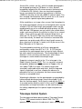
This telescope is known as the Plaskett Telescope, and since
1953 has held on its foundation pier a plaque commemorating
John Stanley Plaskett. The official naming of the telescope took
place on June 4, 1993.
Overview
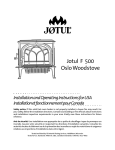
The 1.85-m diameter parabolic primary mirror of the telescope
feeds an f/5 light cone either onto a flat aluminum secondary to
illuminate an imaging focus, or alternatively onto a 0.5-m
hyperbolic convex secondary, to provide an f/18 Cassegrain
focus where the spectrograph is mounted. This telescope has
seen considerable evolution since it went into operation on May
6, 1918, and it is roughly true that only the tube and mounting
remain from the original telescope. The the all-reflection
Cassegrain spectrograph dates from 1967, the Cervit primary
mirror was installed in 1974, and the f/5 modified Newtonian
secondary and imager in 1991. The telescope encoders and
control system are the products of the last decade. Recent
evolution of the telescope has been driven by
"user-friendliness" and safety considerations: the original
centrifugal-governor clock drive has been retired from
operation, the dome shutters and windscreens are now
activated by a remote control handset, and most structures
protruding from the rotating dome have been removed. In late
1993, the telescope tube was enshrouded in a black canvas
mantle to shield out stray light at the imaging focus.
The current style of operation and complement of instruments
is comparable to equipment found at all major observatories,
thus enabling students to gain experience directly relevant to
the use of larger telescopes elsewhere. From the observer's
room on the north side of the observing floor, the Telescope
Control System (TCS) monitors the position of the telescope,
14/07/07 10:11 PM
NRC-HIA: Dominion Astrophysical Observatory
2 of 9
http://www.hia-iha.nrc-cnrc.gc.ca/dao/185_e.html
while a Unix workstation controls data acquisition with
instrument control software (DICE) that is uniform for all
detectors and telescopes at DAO. An adjacent Xterminal allows
field verification from the HST guide Star Catalogue or the
Digital Sky Survey, and permits immediate data transfer and
processing if desired. Routine observing operations can be
performed with ease by a single observer. Observing manuals
are available on-line to guide the observer.
The Cassegrain spectrograph is particularly versatile: its
various apertures, gratings and detectors allow spectroscopy of
objects down to 16th magnitude, at resolutions ranging from
0.4 to approximately 20 Å (lambda/Delta-lambda approximately
200-15000), with signal-to-noise ranging up to 150 or better.
The practical range for spectroscopy is 3600 Å to 9500 Å
subject to the constraints of atmospheric transmission. Long-slit
spectroscopy and sky subtraction features are provided by
using a conventional slit. Fe-Ar and Cd-Ne hollow cathode
sources provide wavelength calibrations, and a tungsten lamp
source provides flat-field calibrations for the spectrograph
configurations.
Telescope Control System
The TCS will automatically position the telescope and dome to
star coordinates of any designated epoch, as entered on the
keyboard. Alternatively, the TCS can set by star number from a
list on the UNIX netwark. See the section on Before You Come
... for the requirements for such a target or "get" list. The TCS
can also accept offsets from a reference star, which can be
useful for setting on very faint objects. The positional encoders
are accurate to approximately 1", but residual errors in the
system limit the whole-sky setting accuracy to something like
20".
For Cassegrain (spectroscopic) observing, the TCS terminal
also controls the light feed into the spectrograph and/or TV
viewer/guider. By choice of diagonal mirror above the Cass
focus, the monitor for the TV guider will display either:
view solid: a full 7' x 6' (alpha x delta) field to magnitude
17, to allow target identification and centering, or
view holey: the outer ring of the 7' x 6' field, to allow offset
guiding while the slit is illuminated by the target object, or
view slit: direct viewing of the slit or image slicer aperture,
to allow guiding on the target object itself. The field of
view is determined by the dekker length adjustment.
view solid or view holey: 1 sec exposure allows detection
to 17th magnitude; a 10 second exposure, to 18.5
magnitude.
view slit : 1 second exposure allows detection to 15th
14/07/07 10:11 PM
NRC-HIA: Dominion Astrophysical Observatory
3 of 9
http://www.hia-iha.nrc-cnrc.gc.ca/dao/185_e.html
magnitude.
Manual guiding of the telescope (either directly on the
slit/image slicer or offset on a guide star, as seen on the TV
guider screen) is accomplished with the keypad buttons on the
TCS keyboard. These buttons move the telescope stepwise by
preset amounts (usually 0.5" when guiding) in the north-south
or east-west directions for each keystroke. Alternatively, an
autoguider may be invoked at the TCS terminal for automatic
guiding on longer exposures.
The TCS will not allow you to set the telescope outside safe
limits: the permitted range of hour angle and declination is
plotted on the safe zone map. There are a number of potential
danger areas within the physical range of motion of the
telescope: collisions between the spectrograph and either pier,
the telescope tube and the north pier, the detector and the hour
angle drive housing and collision between the telescope tube
and the remaining portion of the Newtonian elevator access
platform on the dome. If the TCS accepts any given target
without returning a limit error to the user, it will automatically
negotiate the danger areas to set on that target. This often
results in an apparent slew to a "wrong" position which the TCS
has deemed to be a safe intermediate position; final slew will
begin immediately after the intermediate position is achieved.
In particular, on the safe zone map the telescope will move
from zone 7 to zone 2 through zone 1, from zones 2 to 6
through zone 3, and so forth. As presently cabled, the
telescope is used with the tube east of the piers and must not
be reversed, so it is not possible to circumvent the limits
imposed in the northeast and southeast directions.
It is possible to move either dome or telescope under manual
control with the handset, in which case the TCS will not impose
the plotted limits: instead the operator must use extreme
caution to ensure they are respected, and that the
spectrograph does not approach either pier. Tracking cannot
be engaged under manual control, so the TCS must be
returned to auto control for observing.
Spectrograph Configurations & Exposure
Times
The Cassegrain spectrograph is an all-reflective system, except
for the refractive field flattener just before the detector. Its
optical elements are a 1750-mm focal length off-axis (to avoid
internal obscuration) collimator, a diffraction grating, and a
538.7-mm (21-in) focal length f/5 camera, a diagonal mirror,
and the field flattener. The collimator and camera mirrors exist
as two interchangeable optics sets, differing in their reflective
14/07/07 10:11 PM
NRC-HIA: Dominion Astrophysical Observatory
4 of 9
http://www.hia-iha.nrc-cnrc.gc.ca/dao/185_e.html
coatings. The default set (designated "Al") has standard
aluminum coatings, and is useable over the entire range of the
spectrograph, or approximately 3000-9500 Å. The other optics
set is gold (Au) coated for better reflectivity in the red-near
infrared region, and is available if requested.
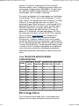
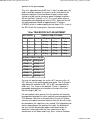
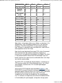
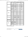
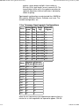
The various configuations of the spectrograph are listed below.
The designation "21181" refers to the combination 21-in focal
length camera, 18-hundred grooves per mm grating, 1-st order,
and so on. All these gratings are used in first order. The
wavelength of peak "blaze" efficiency is so designated; B,G,R
indicate peak efficencies in the blue, green, or red-IR regions.
Peak blaze efficiencies are typically around 80%. The last
column gives approximate exposure times in minutes for
approx. m=12 magnitude star exposed to approx. S/N=30 at
the wavelength of the blaze, with the SITe-5 CCD as detector.
See the section on digital detectors for a comparison of
detectors in their readout noise and spectral response
characteristics. In practice, exposure times also vary widely
according to detector binning, grating rotation, spectral type of
the star, spectrograph aperture, and with the quality of the night
("seeing" and transparency). The best guide for exposure times
is usually to check in the observing log book for an application
similar to your own (particularly spectrograph configuration,
wavelength and detector) and noting the exposure times and
counts.
1.8-m TELESCOPE SPECTROGRAPH
CONFIGURATIONS
NAME
21181
GRATING BLAZE
DISPERSION EXPOSURE
g/mm Angstroms Anstroms/mm minutes
1800
5000
10
60
21121B 1200
4100
15
40
21121R 1200
8000
15
40
2161G
600
5000
30
20
2161R
600
7500
30
20
2141
400
3925
45
15
2131B
300
4200
60
10
2131R
300
6500
60
10
21(3/2)1 150
5000
120
5
Slits & Image Slicers
The slit or one of several image slicers is mounted by wing
clamps at the Cassegrain focal plane, to form the entrance
14/07/07 10:11 PM
NRC-HIA: Dominion Astrophysical Observatory
5 of 9
http://www.hia-iha.nrc-cnrc.gc.ca/dao/185_e.html
aperture to the spectrograph.
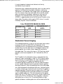
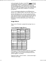
The slit is adjustable from 0.001 inch (1 thou) to wide open; the
width should be matched (in microns) to the resolution of the
detector employed. During conditions of poor seeing, wider
settings may be used to conserve speed, although resolution
will be sacrificed. Typically, a 1.5" slit is used, which allows a
comfortable oversampling with all the CCDs. Note that the 0.8"
slit (with projected slitwidth of approximately 37 microns
(FWHM)) results in undersampling for the larger CCDs, such as
the SITe-5 with 24 micron pixels, 48 micron resolution.
1.8-m TELESCOPE SLIT ADJUSTMENT
SLIT WIDTH
RESOLUTION AT FOCUS
Thou Arcsec microns 10Ang/mm 15Ang/mm 30Ang/mm
5
0.8
37
0.4 Ang
0.6 Ang
1.1 Ang
7
1.1
50
0.5 Ang
0.8 Ang
1.5 Ang
10
1.5
71
0.7 Ang
1.1 Ang
2.1 Ang
13
2.0
92
0.9 Ang
1.3 Ang
2.7 Ang
19
3.0
134
1.3 Ang
2.0 Ang
4.0 Ang
RESOLUTION AT FOCUS
60Ang/mm 120Ang/mm
2.2 Ang
4.4 Ang
3.0 Ang
6.0 Ang
4.2 Ang
8.4 Ang
5.4 Ang
10.8 Ang
8.0 Ang
16.0 Ang
For long-slit spectroscopy, the scale is 6.2" per mm at the slit,
20.1" per mm at the spectrograph focal plane. The slit length is
adjustable with a decker to 20", 40" or 60", corresponding to
widths of 1, 2 or 3 mm on the detector. There is, however, a
perceptible deterioration of resolution at the tips of the lines
with the longest (60") slit.
For well-guided stellar spectra, the sky spectrum will naturally
be exposed alongside the stellar spectrum and recorded on the
CCD detector. Because of the proximity of the city of Victoria,
mercury and sodium emission features from the sky will usually
be recorded on the spectra of stars around 12th magnitude and
fainter, depending on the quality of the night, the direction of
the star, and the wavelength region under observation. At
about the same magnitude, the solar spectrum can be a
contaminant at full moon under hazy skies. In these situations,
14/07/07 10:11 PM
NRC-HIA: Dominion Astrophysical Observatory
6 of 9
http://www.hia-iha.nrc-cnrc.gc.ca/dao/185_e.html
it is quite important to detect and subtract out the sky
contribution to your spectra.
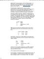
Richardson-type superpositioning image slicers may be used to
optimize slit efficiency at the higher resolutions, where sky
subtraction is not required. Four image slicers are available for
the 21-in camera: they have either blue (B) or red (R) coated
optics for maximum throughput, and come in two levels of
resolution. The resolution of the "very short image slicers"
(VSIS21) is approximately that of the 0.8 arcsec slit given in the
above table. Resolution of the regular (IS21) slicers is usually
limited by the pixel size of the detector.
1.8-m TELESCOPE IMAGE SLICERS
DESIGNATION
APERTURE
SIZE
PROJECTED SLIT
WIDTH
IS21B
3" x 5"
20 microns
IS21R
3" x 5"
20 microns
VSIS21B
4" x 4"
40 microns
VSIS21R
4" x 4"
40 microns
Newtonian Focus Imaging
The modified Newtonian system on the telescope allows direct
imaging at f/5 with any DAO CCD or IR detector. A flat
secondary mirror is installed below the Cassegrain secondary
to direct the axis of the light cone at a 30 degree angle to the
primary optical axis, to form a focus about half way up the
telescope tube. The scale at this focus is 22.5" per mm, which
provides a well oversampled 9.2' x 9.2' field with the SITe-5
CCD.
The TV guider for the Newtonian focus is operated from the
observer's room, and displays a field 7.5' x 6.5' (alpha x delta)
on the monitors. As controlled by the `point' command of the
TCS, the field by the TV guider can be either the the
co-ordinate position entered on the TCS (for field verification),
or else a guide field offset from the detector field, for guiding
during an exposure. Since the pointing errors of the telescope
are small compared to the detector field sizes, field verification
is usually unnecessary; hence the main use of the TV guider is
indeed for guiding! The offset from the center of the CCD field
is fixed: the guider position cannot be rotated or translated to
aquire suitable guide stars. The offset of center of the guider
field on the sky is 18.2 arcmin west and 3.2 arcmin south of the
center of the CCD or IR detector. The autoguider is effective
with guide stars as faint as m~15, but occasionally at high
galactic latitude no suitable guide stars will be found within the
14/07/07 10:11 PM
NRC-HIA: Dominion Astrophysical Observatory
7 of 9
http://www.hia-iha.nrc-cnrc.gc.ca/dao/185_e.html
guider field. For long exposures near the Galactic poles, it is
advisable to verify that guide stars are available before you
come to the telescope. See the `Before You Come' section
below for how to do this.
The photometric capability of the system has been
demonstrated to m=20, and may extend fainter if great care is
exercised in sky subtraction. When configured for CCD
imaging, a filter wheel holding four 50 x 50 mm filters (up to 7
mm thick) is mounted in front of the detector. Alternatively,
three filters and one clear glass aperture (so that the focus is
not shifted) may be used. Johnson-Cousins UBVRI filters are
available. Transformation coefficents to standard UBVRI values
for our filter set depend on the choice of detector. Approximate
transformation coefficent values for the (now defunct) SITe-1
CCD detector are as follows (courtesy of Dave Balam,
University of Victoria):
V coeff = 0.023
b-v
0.990
v-r
0.956 (all are +/- 0.02)
r-i
0.895
Approximate transformation coefficent values for the Tek-2
CCD detector, prior to the last realuminization of the mirror,
were:
V coeff = 0.005 +/- 0.008
b-v
0.944
0.015
v-r
1.014
0.011
Dave Balam, University of Victoria reports on extinction and
transformation coefficients for SITe-5, from the night of July 9,
1998, as follows:
k(v)
k'(bv)
V coeff
b-v
= 0.258
0.159
0.038 (all are +/- 0.01)
0.940
(solution from 13 Landolt standard stars and M92 standards)
The terms are defined by Hardie (Photoelectric reductions Stars and Stellar Systems)
CCD standards field on these pages. -->
For IR imaging, a cooled filter wheel accepting up to eleven 1/2
inch round filters is mounted within the Dewar itself. Infrared
filters available include J, H and Cowie K filters, with central
14/07/07 10:11 PM
NRC-HIA: Dominion Astrophysical Observatory
8 of 9
http://www.hia-iha.nrc-cnrc.gc.ca/dao/185_e.html
bandpasses of 1.25, 1.65 and 2.1 microns respectively.
Filter selection is controlled from the workstation in the
observer's room. Transmittance curves for the above filters are
available on request.
Before You Come ...
In preparing your observing program, the following points
should be kept in mind:
In addition to your base program, plan for a reduced or
expanded program: weather conditions (bad or good) will
often modify your hopes of what is achievable during your
observing run.
Have accurate coordinates; the telescope control system
will accept coordinates of any epoch.
Prepare adequate finding charts for faint objects or
crowded fields; these are mandatory for service observing
projects.
For ease of observing, particularly for projects with many
objects, it is advantageous to write a file containing your
program star list. The format for such a list is straightforward:
for each object, enter on one line the starname, right
ascension, declination, epoch and comments, with spaces or
tabs as delimitors between the fields. If there is a space in the
object name, enclose the name in double quotes; use colons
and leading zeroes in the coordinate fields. For example:
HD47129 06:32:02.4 +06:13:10 1900 V=6.1, Plaskett's star
"Epsilon-2 Lyrae A" 18:44:22.8 +39:36:46 2000 B comp. 2.3"
away; quad system
Lines should not exceed 80 characters. This file will permit
acquisiton of the star by selecting within a Graphical User
Interface (GUI). In order to transfer your file into the DAO
computer network, please contact an observing assistant.
In preparing for a run, it may be wise to prepare charts for field
verification, or to verify that suitable guide stars are located in
the TV guider field (located 18.2 arcmin west, 3.2 arcmin south
of the detector field for the guider at Newtonian focus), using
either the HST Guide Star Catalogue (GSC) or the Digital Sky
Survey (DSS). Both these resources are online at DAO, and
may be summoned at the telescope as needed if you do not
have time to check them before your run. The Digital Sky
Survey may be accessed directly, or from the CADC pages,
and shows stars to much fainter limits than the TV guider will
see, without direct photometric information. The stars of the
GSC, on the other hand, are all sufficiently bright to be suitable
14/07/07 10:11 PM
NRC-HIA: Dominion Astrophysical Observatory
9 of 9
http://www.hia-iha.nrc-cnrc.gc.ca/dao/185_e.html
for guiding with the Newtonian guider.
Published: 2003-06-12
Important Notices
14/07/07 10:11 PM
NRC-HIA: Dominion Astrophysical Observatory
1 of 5
http://www.hia-iha.nrc-cnrc.gc.ca/dao/detect_e.html
CCD Digital Detectors
NEWS
Technical questions? You can email us at
[email protected]
Charge-Coupled Devices (CCDs)
Because of their high quantum efficiency, low readout noise,
large dynamic range, wideband spectral sensitivity and excellent
dimensional stability, charge-coupled devices are now the
detectors of choice for most spectroscopic and imaging projects
on the telescopes. They do have pixel-to-pixel sensitivity
variations of the order of a few percent, which can readily be
calibrated and removed with flat-field exposures on some
uniformly bright source or, for spectroscopic applications, on
some featureless continuum spectrum.
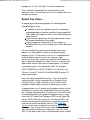
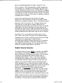
Several of our earlier CCDs (RCA, FA2048, PM512, SITe-1) are
permanently decommissioned, while others such as the Tek-1
and Tek-2 may be occasionally used on an emergency basis. At
the present time, the latter three of the four chips described
below are usually available for mounting at the telescopes:
DAO CCD DETECTOR CHARACTERISTICS
DESIGNATION
UBC-1
Manufacturer Loral
Commissioned Sept/94
SITe-2
SITe-4
SITe-5
SITe
SITe
SITe
Dec/95
Mar/00
June/98
Type
Thick
Thin
Thin
Thin
Illumination
Front
UV
coated
Backside
Backside
Cosmetics
Good
bad
column
V. Good
V. Good
# pixels
4096x200 1752x532 4096x2048 1024x1024
Pixel
15
size(microns)
15
15
24
14/07/07 10:13 PM
NRC-HIA: Dominion Astrophysical Observatory
2 of 5
DESIGNATION
http://www.hia-iha.nrc-cnrc.gc.ca/dao/detect_e.html
UBC-1
SITe-2
SITe-4
SITe-5
Chip size (mm) 61.4x3.0 26.0x8.0 61.4x30.7 24.58x24.58
Readout
noise(e-)
10
~12
6-7
Dark current
0.5
(e-/m)
~11
<0.3
Full well (Ke-) 60
Gain (e-/ADU) 1.5
~1
Range, bits
16
Range, ADU
64K
QE (400nm)
2%
35%
QE (500nm)
20%
70%
QE (600nm)
35%
72%
QE (700nm)
47%
70%
QE (800nm)
32%
57%
QE (900nm)
23%
33%
QE(1000nm)
6%
10%
~1.8
~5
69%
80%
48%
Abreviations in the above table are as follows: e- (electrons), Ke(kiloelectrons), ADU (analogue to digital units), QE (quantum
efficiency). The SITe-3 chip (SITe is a descendent company
from Tektronix) is identical in physical dimensions and similar in
other properties to the Tek-2 chip.
Note that thinned, backside-illuminated CCDs, when illuminated
with monchromatic light, display interference fringing in a
manner that is only partially removable by flat-fielding. The effect
is most pronounced at red and near-IR wavelengths (eg. the I
band), and limits the signal-to-noise achievable when such chips
are used for spectroscopy.
The DAO CCD's are fitted with identical dewars, and hence any
CCD may be used on the 1.85-m Newtonian focus, the 1.85-m
spectrograph, or either of the 1.22-m coudé spectrograph
configurations.
All the current CCDs operate with compatible hardware , and
DICE (DAO Instrument Control Environment) software, thus their
operation appears identical to the user. By the `raster' command,
the observer has control over the area of the CCD to be
sampled, and can invoke on-chip binning. For spectrographic
use, it is common to sample only that area of the detector which
is illuminated by the spectrograph, saving data storage space
14/07/07 10:13 PM
NRC-HIA: Dominion Astrophysical Observatory
3 of 5
http://www.hia-iha.nrc-cnrc.gc.ca/dao/detect_e.html
and readout time. On-chip binning permits pixels to be summed
together in either the serial or parallel direction while keeping the
read noise per sample the same. This feature permits the
sampling of larger areas of the detector without increased read
noise, but at the expense of spatial resolution and particularly
cosmic ray noise resolution, which can be a problem for longer
exposures. Note the values quoted in the table for dark current
and full well are for unbinned pixels, and will increase
proportionally with bin size.
Cosmic Ray Events
All silicon-based detectors record the passage of cosmic ray
muons, which pass relatively unattenuated through the dome
and detector housing. However, the bottom five kilometres of
atmosphere does provide shielding equivalent to about a metre
of lead: at 5000-m altitude there is approximately 1 muon event
per square mm per hour; at sea level this rate is halved. (The
rates also fluctuate with solar activity.) Thus, in cosmic ray
background, low-altitude sites such as DAO offer an appreciable
advantage over higher observatory sites.
Still, cosmic ray events will almost certainly be present on long
exposures taken with a CCD. Their spikes are usually quite
recognizeable in the data, being typically hundreds or thousands
of electrons in intensity, spread over only 1-3 adjoining pixels.
Thus they are easily removed during data reduction.
Cryogens
The CCD detectors are mounted in Dewar flasks which must be
refilled with liquid nitrogen at the start of the night, and also in
some cases during the night and when shutting down at dawn
(but not if another instrument is scheduled to go on the telescope
that day). The liquid nitrogen will be found in reserve flasks,
located on the observing floor near the 1.8-m telescope, and in
the coudé chamber of the 1.2-m telescope. These reserve
Dewars should be pressurized to 10 pounds per square inch
through a plastic hose connection from compressed nitrogen
tanks, in order to expedite filling of the detector Dewars from
them.
As the CCD's are heated from liquid nitrogen temperature up to
approx. -110 degrees C in order to maintain charge transfer
efficiency, their Dewars require regular refilling, typically about
every 8 hours. The CCD Dewars can be completely filled
through a very narrow tube inserted inside a retaining tube,
which requires about twenty minutes. When mounted on the
1.8-m Cassegrain spectrograph, the orientation of the CCD
Dewar is such that it can only be half filled in any case: in this
14/07/07 10:13 PM
NRC-HIA: Dominion Astrophysical Observatory
4 of 5
http://www.hia-iha.nrc-cnrc.gc.ca/dao/detect_e.html
situation a wider filling tube is used, reducing the filling time to a
couple of minutes, and reducing the hold time to about 4 hours.
HOWEVER, the hold time at operating temperature depends on
the individual CCD Dewar, the degree of vacuum of the Dewar
(which itself depends on the elapsed time since being pumped
down, and its thermal history during that interval) and the
orientation of the Dewar cannister at the telescope or
spectrograph (i.e., whether it can be fully filled or not). In normal
circumstances, the SITe-1 CCD at the 1.8-m imaging focus
should remain at operating temperture for up to 12 hours. For
the UBC-1 CCD at the 1.2-m coude focus, the cool-down time is
~3 hours, and the hold time ~7 hours. It is always best to consult
with telescope support staff as to the current hold time for your
particular detector, or look for messages in the observing room
from them on this matter!
The Dewars may require pumping to regain a high vacuum if
they do warm up. Daytime refilling of the CCD Dewars is usually
performed by the telescope support staff on weekdays. On
weekends, the observer is responsible. Automatic refilling of the
Dewars via a timer-controlled valve is an option available to
weekend observers.
For infrared observing, a NICMOS array detector is available;
contact the Telescope Group at
[email protected] for details.
Data Acquisition Computers
The acquisition of data from the CCDs and the IR array is
performed on Sun Workstations from the observer's rooms. The
DAO Instrument Control Environment (DICE) software presents
a graphic user interface that prompts the user for the required
operating commands. Most functions are performed by the click
of a screen button by the mouse. The DICE program allows the
user to define the area of the chip to be sampled, and initiates an
SAOimage window where the data frame is fully displayed.
Monitoring that the CCD remains at operating temperature
during the night can be performed by displaying row or column
plots of bias frames, or of data frames including the overscanned
strip.
The observer's rooms also have Xterminals with which data can
be transferred to an appropriate disk for further storage and
processing. The workstations and Xterminals are linked to the
the rest of the computer system via Ethernet fibre optic link.
14/07/07 10:13 PM
NRC-HIA: Dominion Astrophysical Observatory
5 of 5
Published: 2003-02-27
http://www.hia-iha.nrc-cnrc.gc.ca/dao/detect_e.html
Important Notices
14/07/07 10:13 PM
NRC-HIA: Dominion Astrophysical Observatory
1 of 2
http://www.hia-iha.nrc-cnrc.gc.ca/dao/filters_e.html
Interference Filters
The table below provides a summary of interference filters currently
available for use in the optical imaging camera of the 1.8-m
telescope. We will be adding detailed bandpass information as well
as transmission curves in the near future. For questions regarding
specific filters please contact [email protected].
Observers may also request to use any of a set of narrow-band 2" x
2" filters owned by Dr. Chris Pritchet (UVic). Interested users should
contact David Balam for additional information about the
characteristics and availability of these filters.
Filter
name
Central
Maximum
Bandwidth
wavelength
transmission
(Å)
(Å)
(%)
14/07/07 10:15 PM
NRC-HIA: Dominion Astrophysical Observatory
2 of 2
http://www.hia-iha.nrc-cnrc.gc.ca/dao/filters_e.html
Filter
name
Johnson
Central
Maximum
Bandwidth
wavelength
transmission
(Å)
(Å)
(%)
B - blue
~4238
~60%
V - violet
~5250
~85%
R - red
~5930
~80%
Iinfra-red
~7580
~88%
U - in
house
~3550
~65%
G
9207
R
Gunn
V
I
U
Ströemgren
B
4100
~160
V
4700
~190
Y
5500
~240
U
R
Kron-Cousins
Barr
I
H-Alpha
6564
Red-cont.
6650
PK50
[S-II]
6736
All Filters are 50.8mm square.
Published: 2003-02-27
Important Notices
14/07/07 10:15 PM
NRC-HIA: Dominion Astrophysical Observatory
1 of 8
http://www.hia-iha.nrc-cnrc.gc.ca/dao/12_e.html
Dominion Astrophysical Observatory
The 1.2-m Telescope and Spectrograph
Technical questions? You can e-mail us at
[email protected].
The spectrographs of the 1.2-m telescope are named in
commemoration of Andrew McKellar (1910-1960), who in 1941
made the first measurement of the radiation temperature of the
universe, which became recognized in 1965 as the primodial
cosmic microwave background, a direct remnant of the
cosmogenesis event. The telescope itself is commonly referred
to as the McKellar Telescope.
Overview
The 1.2-m telescope was inaugurated in March 1962, and a
new primary mirror was installed in April 1985. The current
primary mirror is a low-expansion borosilicate glass called
Ohara E-6; its coefficient of thermal expansion is about
two-thirds that of Pyrex. During optical shop testing of the
uncoated primary mirror in 1984, 70% of the light was
concentrated within 0.5 arcsecond, 90% within 0.8", and 98.5%
within 1.0" at prime focus. Thus the mirror quality considerably
excels over typical seeing-limited image sizes obtainable at the
DAO site.
As with the 1.8-m telescope, much effort in recent years has
gone towards making the telescope and its instruments
user-friendly and relevant to the training of students. The
telescope and dome are under computer control from the
ground-level observer's room. Automatic dome tracking is an
added advantage for long exposures.
The 1.2-m telescope is normally used at the coudé focus, with
high-reflectance coatings for the second, third, fourth and fifth
mirrors to optimize throughput. The three mirror sets are Super
Blue (3500-5300 Å), Aluminum (4500 Å-near IR) and Gold
(6500 Å-IR) optics. These mirror sets are rapidly
interchangeable and self-aligning, so that it is possible to
change from one set to another in about two minutes, without
the need to re-centre on the star being observed. The coudé
beam is f/145 after reflection from the hyperbolic secondary
14/07/07 10:34 PM
NRC-HIA: Dominion Astrophysical Observatory
2 of 8
http://www.hia-iha.nrc-cnrc.gc.ca/dao/12_e.html
(third to fifth surfaces are flat), while the coudé spectrographs
are designed to accept an f/30 beam, so a lens located
immediately following the fifth mirror converts the beam from
f/145 back to f/30. Actually, there are two interchangeable
lenses, one coated for maximum transmittance in the blue
(<5000 Å), the other for the red (>5000 Å) spectral region. The
lens selected should conform with the mirror set in use, and of
course with the spectral region being observed.
At the coudé focus, an image slicer ensures high throughput to
the coudé spectrograph, where one of two optical paths may be
selected. A 32-inch focal length spectrograph camera can be
combined with one of six available diffraction gratings (of 300,
600, 830 and 1200 grooves per mm) which have various blaze
angles, and some of which are efficient in either first or second
orders. These yield many possible reciprocal dispersions, of
which 6.5, 10, 18 and 41 Å per mm are the most commonly
used. Alternatively, the beam can illuminate a mosaiced 830
groove per mm grating and a 96-inch focal length camera to
give a spectrum in the red (1st order) at 4.8 Å per mm or in the
blue (2nd order) at 2.4 Å per mm.
The corresponding resolution of all these spectrograph
configurations ranges from 0.07 to 1.2 Å. A CCD may be
mounted at the spectrograph focal surface for highly efficient,
low-noise spectral measurements. The disadvantage of these
detectors is their small physical dimension, which allows
coverage of a rather modest wavelength range.
A popular instrument specific to the 1.2-m telescope is the
Radial Velocity Scanner (RVS). This is a versatile instrument
designed for photoelectric measurement of Doppler shifts of
stars about 7,000 K or cooler. The velocity range to be
searched is adjustable within wide limits, and the integrated
signal is displayed in real time, allowing the observer to
proceed to the next star whenever the measurement quality
reaches an acceptable level.
Wavelength calibrations for the spectrographs are provided by
hollow cathode discharge lamps; three are available: Fe-Ar
(best for the blue region), Cd-Ar (mainly used with the RVS, so
as to avoid conflict with the stellar Fe lines) and Th-Ar. Various
configurations of lamp illuminations can be used for detector
flat fielding, depending on the spectral region and precision
required.
Telescope Control System
The telescope and dome operate under a Telescope Control
System (TCS) commissioned in March 1995. The TCS
operates from a terminal in the observer's room, although both
14/07/07 10:34 PM
NRC-HIA: Dominion Astrophysical Observatory
3 of 8
http://www.hia-iha.nrc-cnrc.gc.ca/dao/12_e.html
telescope and dome can be moved under handset control from
the observing floor if required. The TCS accepts coordinates of
any specified epoch, and the commands it accepts are almost
identical to those used on the 1.8-m telescope. The setting
accuracy is currently about 15" over the whole sky (but much
more accurate over a restricted region of the sky). The
direct-viewing coudé field is only 3' diameter. A TV viewer
eases guiding on faint objects, but is not usually necessary for
m<10. The TV guider views either an area 3.1' × 2.4' in the field
or else 1.2' × 0.9' around the image slicer aperture.
The telescope cannot collide with the dome nor with any
obstructions on the observing floor (with the sole exception of
the ladder if it is improperly stowed). The polar axis is rotatable
through more than one complete rotation, but is ultimately
limited in travel by the cabling to the telescope. In the normal
position (with the telescope tube east of the pier at the
meridian), the limits in hour angle are 7.7 hours east to 20
hours west. If you plan to monitor a circumpolar object from
(say) 9 hours east through 3 hours east, you can still do so
without encountering these limits by reversing the telescope.
This is done by driving the telescope through the north pole,
and setting on a readout right ascension offset 12 hours from
the desired coordinate. In this case the hour angle range which
is attainable is also offset by 12 hours, viz. 19.7 hours east
through 8 hours west. Note there is also a limit switch in
altitude, which will cut off the telescope drive at 8 degrees
above the horizon. The above limits suggest that the entire sky
above 8 degrees altitude is accessible to the telescope. This is
not really achievable in practice, as trees obscure the eastern
and southern horizons to as high as approx. 20 degrees
altitude in some directions. A practical limit in declination (near
the meridian) is thus about -30 degrees.
Spectrograph Configurations & Exposure
Times
The coudé spectrograph optics are described in detail by E.H.
Richardson in JRASC 62, 313 (1968). Basically, there are two
separate spectrographs in the coudé room, each with its own
collimator/camera combination:
"96"
"32"
For highest dispersion, a 7600-mm focal length collimator
illuminates a mosaic of four identical 830.8 g/mm
gratings, whose dispersed light is focussed by a
2432-mm (96-in) focal length, on-axis camera at f/8.
For intermediate dispersions, one of two 4500-mm focal
length collimators illuminates one of six available
14/07/07 10:34 PM
NRC-HIA: Dominion Astrophysical Observatory
4 of 8
http://www.hia-iha.nrc-cnrc.gc.ca/dao/12_e.html
gratings, whose dispersed light is focussed by an
813-mm (32-in) focal length, on-axis camera at f/5. The
two collimators differ only in the aspheric correction for
spherical aberration; choice of collimator is dictated by
choice of grating.
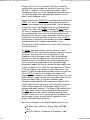
Spectrograph configurations are designated thus: 9682M for
96-in camera, 830 g/mm Mosaic, 2nd order, and so on. The
available configurations are:
1.2-m Telescope Spectrograph Configurations
Name
Grating Blaze
g/mm Ang
Range
Ang
Dispersion
Ang/mm
9682M 830M
4060 3500-5800 2.4
9681M 830M
8125 5800-9900 4.8
32121
5000 3600-6500 10.1
1200
32121H 1200H 6000 5000-8500 10.1
32122
1200H 3000 3200-4000 5.0
3282
830
4060 3500-6000 6.5
3281
830
8125 6000-9900 13.1
3261
600
4000 3200-5000 17.9
3261H 600H
7000 5000-9500 17.9
3262
600H
3500 3200-4200 9.0
3231
300
4200 3500-8000 40.9
Name
Exposure Exposure
CCD (min) Photo (min)
9682M 15.0
150
9681M 3.0
--
32121
3.0
20
32121H 2.0
30
32122
--
--
3282
3.0
30
3281
1.0
--
3261
1.0
10
3261H 2.0
15
3262
2.0
20
3231
0.5
4
where the last two columns give approximate exposure times in
minutes for a sixth magnitude star exposed to approx. S/N=30
14/07/07 10:34 PM
NRC-HIA: Dominion Astrophysical Observatory
5 of 8
http://www.hia-iha.nrc-cnrc.gc.ca/dao/12_e.html
at the wavelength of the blaze, for the SITe-2 CCD and Kodak
IIa photographic emulsions, respectively. Because of the wide
dynamic range of CCDs, actual exposure times may vary
considerably depending on the signal-to-noise required by the
observer. A single-scale exposure meter allows comparison of
exposures taken under different conditions of seeing and
transparency.
For the spectrograph configurations using 830 groove/mm
gratings such as 9682M, 9681M, 3282 and 3281 (which all use
gratings replicated from the same master grating), efficiency
curves are available here for first order reflection and second
order reflection to allow an informed choice of which order will
perform best at a given wavelength. On these plots, the
reflectance of a freshly aluminized surface is also shown for
comparison.
Image Slicers
There are four Richardson superpositioning image slicers as
follows:
1.2-m Telescope Image Slicers
Designation
Aperture
Actual
Range
Dimension Slit Width
Ang
"
microns
IS32B
5000
3.5 × 2.5
112
IS32R
>5000 3.9 × 2.5
112
ISRVS
<5000 3.8 × 5.6
250
IS96B
<5000 5.2 × 1.4
62
Projected Projected
Designation Width (32) Width (96)
microns microns
IS32B
20
36
IS32R
20
36
ISRVS
45
80
1596B
11
20
where the first number of the aperture dimension is the height
in arcseconds. As seen through the image slicer guiding
eyepiece it appears as the narrow vertical dimension of the
entrance aperture. The relation:
Projected slit width = Actual slit width × (Camera focal length /
Collimator focal length)
14/07/07 10:34 PM
NRC-HIA: Dominion Astrophysical Observatory
6 of 8
http://www.hia-iha.nrc-cnrc.gc.ca/dao/12_e.html
gives the tabulated projected slit widths for both 32- and
96-inch cameras. Since the projected slit width should match
the resolution (i.e., two pixels) of the detector, the IS32's are
normally adequate for either camera, and the IS32R should be
used for all red configurations in any case. Although the ISRVS
is intended for use with the Radial Velocity Scanner, the IS32B
may be used in its place as this results in a significant reduction
in guiding errors in velocity.
Image slicers greatly enhance the efficiency of coudé
observing, as they effectively increase the slit width fourfold
without loss of spectral resolution. That is, at the 5.6 arcsec per
mm "plate scale" of this focus, the 112 micron width of the
IS32's passes as much light as would a 450 micron slit,
neglecting internal reflective losses within the slicer. A second
advantage is that they enable light slices passing from the
grating to the camera to pass above and below the flat mirror
used to reflect light returning from the camera into the detector,
thereby avoiding internal obscuration from the on-axis design.
An ordinary slit is very inefficient for stellar sources at this
focus, and is rarely used. It may be used for spectroscopy of
extended sources such as cometary comae (where the image
slicer presents no advantage), in order to retain
one-dimensional spatial resolution along the slit. The ordinary
slit is adjustable for widths of 75 microns (0.003-inch) and
larger. When using the ordinary slit, the square mask on the
collimator should be replaced with a round one.
Radial Velocity Scanner
The Radial Velocity Scanner (RVS) is installed on the 9682M
spectrograph: a removeable diagonal mirror just before the
focal surface directs the light into the scanner. The instrument
is based on the prototype RVS built by Roger Griffin at
Cambridge Observatories. That is, a mask resembling an
ultrahigh-contrast negative of a late-type stellar spectrum is
scanned back and forth through the focal surface: when the
windows of the mask coincide in position with the principal
stellar absorption lines, a minimum amount of light is passed
through to a photomultiplier; the position at which this minimum
occurs is a measure of the Doppler shift of the star under
observation. The DAO RVS has a number of unique
refinements, however. One is that the masks are etched from
copper on glass, for maximum transmission. Also, the mask
windows or slits are not parallel, but are tilted slightly with
respect to the line of dispersion. By scanning the mask at a 45
degree angle in the focal surface the effect of the tilted lines is
to stretch or shrink the mask to maintain proper registration at
all velocities. Currently there are spectral masks based on
14/07/07 10:34 PM
NRC-HIA: Dominion Astrophysical Observatory
7 of 8
http://www.hia-iha.nrc-cnrc.gc.ca/dao/12_e.html
Procyon (F5) for F-stars, on Arcturus (K2) for G, K and M
spectral types, and a carbon-star mask for C-type stars. Thus
the RVS is suitable for all stars cooler than about 7,000 K.
Following the mask, sets of five superpositioning mirrors focus
the transmitted light onto a photocathode, whose small size
permits minimal detector noise.
Another feature of the DAO RVS is the Guiding Error Minimizer
(GEM). This consists of an image rotating prism located just
after the spectrograph slit in the coudé room. The two positions
of the prism result in two images of the slit, one inverted with
respect to the other. If the GEM is invoked, the RVS records
five scans in one position of the prism, followed by five scans in
the inverted position; thus if the star is de-centred on the slit
during this time, the non-uniform illumination will not result in a
velocity-like shift of the spectrum at the mask. Also, the RVS
mask position is continously monitored by an encoder which is
checked relative to the stepper motor position: if any
discrepancies or discontinuities occur, an on-screen warning is
sent to the observer.
The RVS is operated remotely from the observer's room.
Repeated scans over a preselected velocity range are summed
(to remove seeing and transmission fluctuations), and
displayed on an oscilloscope screen. When a well-defined
minimum is visible, the observer can interrupt the scan to
compute a velocity. Generally a two minute integration yields
precise velocities for magnitudes B<=9; somewhat longer
integrations (approx. 30 minutes) extend the observable range
as faint as approx. B=15. Since the Telescope Control System
(TCS) can acquire a star typically in one or two minutes, this
means it is quite feasible to observe about fifteen stars per hour
with the RVS, at least for stars brighter than about ninth
magnitude whose velocities are approximately known. For stars
whose velocity is quite unknown, it usually takes some time to
locate the velocity "dip". On-line data reduction yields
heliocentric radial velocities with a precision of about 0.2-0.3
km per second; these require only small zero-point corrections
(from a hollow cathode arc and standard velocity stars) to
become publishable velocities. The velocity "dip" profiles which
the RVS records are also transferred directly into an archive
area. This permits more sophisticated data reduction later if
needed; in most cases, this is necessary only for double-lined
spectroscopic systems of small velocity separation, which
display a blended velocity minimum.
For further information on the Radial Velocity Scanner, see:
Fletcher, Harris, McClure & Scarfe, 1982. PASP 94,
1017.
McClure, Fletcher, Grundmann & Richardson, 1985.
14/07/07 10:34 PM
NRC-HIA: Dominion Astrophysical Observatory
8 of 8
http://www.hia-iha.nrc-cnrc.gc.ca/dao/12_e.html
Stellar Radial Velocities, IAU Colloquium # 88, p.49.
Before You Come ...
If you will be using the RVS, you should enter your list of
program stars into a data file before your run commences, as it
will greatly expedite your observing procedure. The format for
such an observing list is the same as for the 1.8-m telescope.
Published: 2003-05-12
Important Notices
14/07/07 10:34 PM