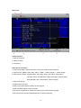
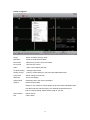
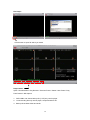
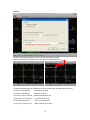
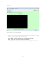
1
Thank you for purchasing our product.
Please read this User’s Manual before
using the product. Change without Notice
8 Channel Digital Video Recorder
User’s Manual
Safety Precautions
CAUTION
RISK OF ELECTRICAL
SHOCK. DO NOT OPEN !
CAUTION: TO REDUCE THE RISK OF ELECTRICAL SHOCK,
DO NOT REMOVE COVER (OR BACK), NO USER
SERVICEABLE PARTS REFER SERVICING TO
QUALIFIED SERVICE PERSONNEL.
The lightning flash with arrowhead symbol, within an equilateral
triangle, is intended to alert the user to the presence of insulated
dangerous Voltage within the product’s enclosure that may be
sufficient magnitude to constitute risk of electrical shock to persons.
The exclamation point within an equilateral triangle is intended to alert
the user to the presence of important operation and maintenance
(servicing) instructions in the literature accompanying the appliance.
WARNING: TO PREVENT FIRE OR SHOCK HAZARD, DO NOT
EXPOSE UNITS NOT SPECIFICALLY DESIGNED FOR
Attention: installation should be performed by qualified service
Personnel only in accordance with the National Electrical Code or
applicable local codes.
Power Disconnect. Units with or without ON-OFF switches have
power supplied to the unit whenever the power cord is inserted into
the power source; however, the unit is operational only when the
ON-OFF switch is the ON position. The power cord is the main power
disconnect for all unites.
Warranty
There are no serviceable parts for this unit, call for your agent for
details.
and Service
2
About this document
Before installing stand alone DVR, be sure to thoroughly review and follow the instructions in
this Users Manual. Pay particular attention to the parts that are marked NOTICE.
Also, when connecting with external application, first turn the power OFF and follow manual
instruction for appropriate installation.
Before reading this document
1. This document is intended for both the administrator and users of stand alone DVR
Model.
2. This manual contains information for configuring, managing and using stand alone
DVR Model.
3. To prevent fire or electrical shock, do not expose the product to heat or moisture
4. Be sure to read this manual before using stand alone DVR Model.
5. For questions and technical assistance of this product, contact your local dealer.
►Strong recommendation on installation of the DVR unit
1. Check electricity at the place you want to install the DVR unit is stable and meets our
electricity requirements. Unstable electricity will cause malfunction of the unit or give
critical damage to the unit.
2. Several chips on the main board of the DVR unit and hard disk drive inside the unit
generate heat, and it must be properly discharged. Do not put any objects just beside
exhaust port(fan) on the left side of the unit and do not close up an opening (fresh air
in-take) on the right side of the unit..
3. Put the DVR unit at well-ventilated place and do not put heat-generating objects on the
unit. When it is installed inside 19 inch mounting rack together with other devices,
please check built-in ventilation fan of the rack is properly running.
3
FCC Statement:
WARNING
This device complies with Part 15 FCC Rules. Operation is subject to the following two
conditions: (1) This device may not cause harmful interference. (2) This device must
accept any interference received including interference that may cause undesired
operation."
* Federal Communications Commission (FCC) Statement
WARNING
This Equipment has been tested and found to comply with the limits for a Class B digital
device, pursuant to Part 15 of the FCC rules. These limits are designed to provide
reasonable protection against harmful interference in a residential installation. This
equipment generates uses and can radiate radio frequency energy and, if not installed
and used in accordance with the instructions, may cause harmful interference to radio
communications. However, there is no guarantee that interference will not occur in a
particular installation. If this equipment does cause harmful interference to radio or
television reception, which can be determined by turning the equipment off and on, the
user is encouraged to try to correct the interference by one or more of the following
measures:
- Reorient or relocate the receiving antenna.
- Increase the separation between the equipment and receiver.
- Connect the equipment into an outlet on a circuit different from
that to which the receiver is connected.
- Consult the dealer or an experienced radio/TV technician for help.
* You are cautioned that changes or modifications not expressly approved by the party
responsible for compliance could void your authority to operate the equipment.
4
FRONT PANEL
1.
/
: Quad screen mode button
2.
CHANNEL 1 / 5
: Channel 1 / 5 full screen button
3.
CHANNEL 2 / 6
: Channel 2 / 6 full screen button
4.
CHANNEL 3 / 7
: Channel 3 / 7 full screen button
5.
CHANNEL 4 / 8
: Channel 4 / 8 full screen button
6.
LOCK
: Press this button to Key Lock function
7.
AUDIO
: Audio on or off button
8.
AUTO
: Auto sequence mode
9.
BACKUP
: Image backup button
10. UP / STOP
: Direction button UP / Playback stop button
/
11. DOWN / PAUSE
: Direction button down / Playback pause
12.
REW / LEFT
: Reverse playback choose button / play speed
/
13.
FF / RIGHT
: Forward playback choose button / play speed
/
/
14. ENTER
: Enter button or value change(+) / Shift mode(S)
15.
MENU BUTTON
: Press this button to display the menu setup
16.
ESC / PTZ
: Press this button to exit menu / PTZ mode
17.
T-SRH
: Press this button to playback time search
18.
PLAY BUTTON
: Press this button to playback
19.
+ BUTTON
: Increase + values change.
20.
REC BUTTON
: Press this button to start recording image
21.
- BUTTON
: Reduce - values change
22. USB 2.0
(Step play)
: Pan Driver slot
*User needs to plug in USB again if ActiveX loaded; image backup or version updated.
5
REAR PANEL
X
Power code in 12V/5A, power switcher (ON / OFF)
Camera 1 ~ 8 input BNC type
Monitor out
VGA out (Optional)
Audio channel input x 1 and output x 1
Alarm / Relay / RS 485 connector
RJ-45 (Network connector)
PS 2 type mouse connector
RS232/ISP: Not available
6
DVR Initialing
or detect a new hard disk
**Notice**
Please set HDD to Master if only one
installed.
Recording icon
Overwrite
Motion
Alarm
Live screen
Event (Motion / Alarm)
Video loss
Keypad lock * 111111 is the default password
On live, press Enter button to (Shift) mode + 1; 2; 3 ; 4 switch to 5; 6; 7; 8 full screen.
Hard Disk capacity; Hard Disk capacity used; Network Type and IP address information
7
Mouse Control
1 Screen display
○
1. Double-click of the left button on desired camera
to full channel
2. Double-click of the left button on desired camera
1
○
2
○
to 9 split screen
3
○
3 Menu display
○
1. One-click of the right button to menu OSD
2. Back to last OSD page
2 None
○
No function
1 Select
○
1. One-click on the item of OSD
2. One-click on the value of item
3. One-click on the Exit to quit and save menu
4. From right-up to left-below and the set motion
detect area
Operate:
MENU BUTTON
: Press MENU button to enter menu setup or exit
ESC / PTZ
: Press ESC button to exit menu / To PTZ control mode
ENTER BUTTON
: Press Enter button to confirm set or value change(+) / Shift mode
DIRECTION BUTTON : MENU item select
+ BUTTON
: Increase + values change
- BUTTON
: Reduce - values change
BACKUP
: To backup mode
(
) MOVE (ENT) SELECT (MENU) EXIT
8
Remote controller (Optional):
The key on the remote controller function control is same as DVR keypad. Only a few keys are
no avail.
Channel select 1 ~ 8 camera
XX
Quad / Split screen
X
X
PIP: Audio hot key
Auto: Channel sequence
X
UP / STOP : Direction button UP / Playback stop button
REW
: Reverse playback choose button
DOWN / PAUSE : Direction button down / Playback pause
FF
: Forward playback choose button
ENTER
: Enter button or value change / Shift mode
MENU BUTTON : Press this button to display the menu setup
BKUP
: Image backup button
ESC / PTZ
: Press this button to exit menu / PTZ mode
T-SRH
: Press this button to playback time search
PLAY
: Press this button to playback
REC BUTTON
: Press this button to start recording image
+ BUTTON
: Increase + values change
- BUTTON
: Reduce - values change
9
Main MENU – Camera Set
Right adjustment of each element will increase picture quarterly displayed. We recommend
you to adjust each element of cameras and monitor to be connected to the DVR unit.
Main MENU – Camera Set – Display (Channel mask, but it still do recording.)
10
Main MENU – Camera Set – Title
Camera title setup function allows 5 characters for each channel.
Select Shift to next page and then Enter to confirm camera title.
11
Main Menu – Record Set
Record Set – Record Framerate
Record Set – Record Quality
Record Set – Event Rec Duration
High / Normal / Low
5 / 10 / 15 / 20 / 25 / 30
Record Set – Auto Record
Record Set - Data Retention Set
After 1 ~ 8 minutes, auto start to record
1 ~ 15 days
if no operation.
12
Record Set – Schedule Record
Notice:
1. Each channel has own frame rate adjustment of each recording mode.
2. In 24 hours, user can adjust each channel frame rate of different record mode. Such as
schedule, motion detection, and alarm record more.
3. Press
button to change 4 different of record modes.
1. Schedule record mode
2. Motion record mode
3. Alarm record mode
4. Motion + Alarm + Schedule record mode
13
Notice:
The enable frame rate is from 3 fps to 60(NTSC) / 50(PAL) fps per single channel recording.
DVR takes a while (3 ~ 5 seconds) to play data from HDD if the frame rate sets to low.
Record Time Table: 80GB HD
Record Quality: Low. KB Range: Lowest: 13, Highest: 20. Average: 17.
REC FPS
60
30
15
10
REC Hour
22
44
87
131
Record Quality: Normal. KB Range: Lowest: 15, Highest: 28. Average: 22.
REC FPS
60
30
15
10
REC Hour
15
34
67
101
Record Quality: High. KB Range: Lowest: 19, Highest: 45. Average: 32.
REC FPS
60
30
15
10
REC Hour
12
23
46
69
Actual recording time is base on live environment. This table is only for reference.
14
Main Menu – Alarm Detection
Alarm Signal type depends on Alarm Sensor polarity define on NO (N/Open) or NC (N/Close)
mode. Alarm POP UP: Event channel jump to full screen when alarm triggered. Quad screen
with the alarm symbol if more than two cameras triggered.
Door closed
Door open
Relay: NO + COM or NC + COM
Alarm Signal type depends on Alarm Sensor polarity define on NO (N/Open) or NC (N/Close)
mode.
NO + COM: Normally, motion relay is NO + COM connector.
Relay action:
Relay: NO (Normal open)
NO
Alarm trigger
COM
Relay: NC (Normal Close)
NC
15
COM
Main Menu – Motion Detection
Main Menu – Motion Detection – Motion Area
cursor
Detected area
Motion POP UP: Motion channel jumps to full screen
when motion triggered. Quad screen with an alarm
symbol if more than two cameras.
Main Menu – Motion Detection – Motion area selection
Direction button Left or Right + ENTER to cancel detection area.
Select start (right-up corner) point and end (left-below corner) point of detect area.
Start
End
One-click of the mouse left button to cancel detect area.
Select start (right-up corner) point and end (left-below corner) point of detect area.
16
Main Menu – Screen – Border: Quad border On / Off display
Main Menu – Screen – Video Adjustment: Video screen position movement
Main Menu – Screen – VGA Frequency and VGA
After adjusted, press ENTER to see if it has change the dialogue resolution, press ENTER to
change, press ESC to cancel. If user does not make any change, the mode will change back to
last status after 15 seconds.
DVR needs to reboot if 1280x1024 resolution adjusted.
17
Main Menu – Audio Set
- If microphone, audio line in or any how, user please set the audio record mode to on and also
adjust volume input or output to right sound effects.
- Mute means live audio is turn on or quiet.
Main Menu – System Set – Hard Disk
Main Menu – System Set – Format HDD
Main Menu – System Set – Hard Disk Setup – Format HDD – Password
18
HDD was formatted successful.
- Before hard disk format, user needs to put the right password. The password is same as
unlock which is default 111111.
- Please set HDD to Master if only one installed. Second one to Slave.
- Hard Disk Master and Slave jumper pin must right, otherwise it makes DVR work fault.
Main Menu – System Set – Password Change
Default is 111111.
Shift to next page and enter to confirm new password.
19
Main Menu – System Set – Time Set
Select time zone and auto time synchronization with NTP server. Network is required on NTP
server. NTP server does not work under network DHCP mode. After time set or daylight mode
turns to on, user needs to Apply and confirm. 0 ~ 9 is repeatable with increase + button,
And decrease - button is opposite.
Main Menu – System Set – Dwell Time Setup (Channel auto sequence)
Main Menu – System Set – Network Settings
20
Network Settings – Local IP
Network Settings – Local IP – STATIC
Network Settings – Local IP – DHCP
Select static IP address / Gateway / Net Mask
Auto IP detected under IP sharing or router
Main Menu – System Set – Network – PPPOE
Main Menu – System Set – Network – PPPOE – ID
21
Main Menu – System Set – Network – PPPOE – Password
Input PPPoE account and password. And then save & exit menu. After a while, back to
network set again, user would see IP appears.
IP would not correctly appear on screen if any firewall or router authority management.
User type the IP to Net viewer or IE browser to view image via network.
Main Menu – System Set – Network – D/DNS set
22
Ex: Enter in www.dyndns.com to apply a free account and host name.
Click Create Account to make a new ID name.
Fill in all the personal information, password, email requested; please go to user’s email
account to active your new account. Return to DynDNS website; click Account to long in page.
cv1000
123456
Type your applied Username and Password
23
Logged In page
Click “My Services” icon
Click Add Host Services:
Click “Add Host Service”
24
Add static DNS Host:
Select Static DNS: add Static DNS Host
Type a Hostname user decided.
No useful
df6020
25
Add Host
Ex: Create a new df6020 host name, after add a new host name; DynDNS page shows a
confirm message page.
Enable :
YES
DNS Server: From ISP
DDNS Server: DynDNS.
HOST Name: Insert host name
User Name: Insert DynDNS username
Password:
Insert DynDNS password
On IE browser blank bar, type df6020.dyndns.org; and then user can get on line.
DNS address is required.
Network stream speed depends on the locality bandwidth.
Advice user apply network speed Upload 512K / Download 512K or more, to avoid image data
too big influence the remote quality.
26
Main Menu – System Set – RS-485
It follows the camera baud rate
Don’t care
Don’t care
Don’t care
Main Menu – System Set – Pan/Tilt Device
Control: Keypad, mouse
* Mouse control: press ESC to PTZ mode, press AUTO button, and then once-click left button
of mouse to control PTZ movement.
Press quad button + number 1 ~ 4 button to set presets, press AUDIO + 1 ~ 4 to call preset.
Press AUTO to start auto presets, AUTO again to cancel.
Up/Down/Left/Right: PTZ dome direction control
+ / - : Zoom in / Zoom out
27
Main Menu – System Set – F/W Upgrade
Stop all hard disk working before update, select F/W upgrade and then press ENTER to
search firmware.
Press PLAY to start version update.
DVR auto reboot after version update.
HDD needs to be installed before update.
28
Main Menu – System Set – BUZZER SETUP
Main Menu – System Set – Load Active-X Control
Stop all hard disk working before load Active-X control
1. Before DVR IE connection, please download the ActiveX to DVR hard disk from CD-ROM,
and then you can view DVR image via internet any PC.
Steps: CD disk Æ ActiveX ÆUSB pan drive Æ DVR (with hard disk) USB Æ
Menu - System Set – Load Active-X Control Æ ENTER button
2. Also install ActiveX to your personal computer. Net viewer is packaged with ActiveX.exe.
29
Main Menu – Search
Main Menu – Search – TIME LIST
Main Menu – Search – Event List
Main Menu – Search – Time Search
Press ENTER to select date and time. Direction left and right button to move value item.
ENTER or + / - button to change value.
30
Main Menu – Search – Time Search: after date and time select, go to Search and then
press ENTER to start playback.
Playing
Forward speed: x 2 / x 3 / x 4
(Direction right button)
Reverse speed: x 8 / x 16 / x 32 (Direction left button)
31
Backup mode: Before backup, USB pan driver is required.
Mode 1: On live mode, press backup button to file backup page.
Total hard disk date & time range
Select start and end time of backup
After select backup time, apply to count
data size. After size appears, press backup
button to USB page.
DVR is reading pan driver
After a while, all backup information display on screen, user now can press backup button to
start file backup.
32
Data is writing to USB pan drive, users please wait until backup complete. Press menu button
to quit USB page.
Mode 2: Press play button to start playback, the playback beginning time is the last one hour
record. Press + and – to select backup time. User only can increase seconds in this backup
way. Press backup button to USB page which is same as mode 1.
Mode 3: On mode 2, user can press T-SRH button to the page like mode 1, and then to
mode 3.
Here, user only can adjust End date and time, after the back way is same as mode 1.
33
Mode 4: On event list, choose an event record data, and then press backup button.
Pages go to USB page, after data size appears, press backup button to the page
which is same as mode 1
34
Main Menu – Language – English or Chinese
Main Menu – Exit
User needs to save changes if any function value has changed. And then exit menu.
Operate:
MENU BUTTON
: Press MENU button to enter menu setup or exit
ESC BUTTON
: Press ESC button to exit menu / PTZ mode
ENTER BUTTON
: Press Enter button to confirm set or value change(+) / Shift mode
DIRECTION BUTTON : MENU item select
+ BUTTON
: Increase + values change
- BUTTON
: Reduce - values change
BACKUP
: To backup mode
(
) MOVE (ENT) SELECT (MENU) EXIT
35
Net viewer
c
d
i
j
e
f
g
h
Viewer function:
1. Backup file player
2. Network viewer
3. Connection
DVR control via viewer:*
4. DVR screen: Split, Channel full screen / Key lock / Channel auto sequence.
5. DVR function: MENU / ESC / Play / REC / T-SRH / - values change / + values change
6. DVR direction button: Up (Item select, Play Stop) / Down (Item select, Play Pause)
Left (Item select, Play Reverse) / Right (Item select, Play Forward)
ENT (ENTER): Item confirm/select, values change)
7. DVR menu pop-up
8. Audio volume (PC site)
*Viewer control panel button is same as DVR keypad.
*Viewer and DVR display is synchronously.
*PTZ control is supported on viewer and control way is same as DVR keypad.
*PTZ control and movement speed depends on network streaming.
36
Viewer configures:
Player
Switch to backup file play mode
Netviewer
Switch to DVR network viewer
Disconnect
Network log out and connect canceled
Dvr Control
DVR function control
Audio
Audio volume adjust (PC site)
Local Recording
Viewing image record
Always On Top
Player or viewer always on top even other data folders open
Full Screen
Viewer change to full screen
Maximize
Full screen display
Aspect Ratio
Resolution 640 x 448 / 640 x 544 adjust
Options
Viewer function setup
Always on Top: Player or viewer always on top even other data folders open
Auto Reconnection: Reconnection if non artificial network disconnect.
Path for local recording: Please select a path of your PC.
About Viewer
Viewer version
Exit
Close viewer
37
File Player:
Click browser to open file which you saved
Player button
Open \ Fast Backward \ Play Reverse \ Previous Frame \ Pause \ Next Frame \ Play
Fast Forward \ Still Capture
1. DVR USB or net viewer backup file (*.VVF)only read in player
2. Local recording file only read in player, except transfer to AVI.
3. Backup file includes video and audio
38
Player Configure:
Player
Switch to backup file play mode
Netviewer
Switch to DVR network viewer
Open File
Open the backup file which saved in any path
Open Disk
Open the DVR hard disk which is installed to PC IDE slot
Export
Backup file to AVI files transform (Video + Audio). See AVI page
Close
Player Button control disable
Show time
Show the backup beginning time
Always on Top
Player always on top even other data folders opened
Playback
Play back mode and speed select. Same as Player button
Audio
Audio volume adjust (PC site)
Full screen
Player screen to full size
Maximize
Player to full of screen
Aspect Ratio
Player resolution adjust
Options
See Next page
About viewer
Version of viewer
Exit
Player and viewer exit
39
Options
User creates or selects a record path
Always on top: Player always on top even other data folders opened
Show time: Show the PC time of when user start recording backup file
On Screen display date/time (Show time) format: Please select the date format you want.
%Y/%m/%d %H:%M:%S:
2007/06/15 15:32:29
%y/%m/%d %H:%M:%S:
07/06/15 15:32:29
%Y/%m/%d %p %I:%M:%S: 2007/06/15 PM 03:32:29
%y/%m/%d %p %I:%M:%S:
07/06/15 PM 03:32:29
%b %d %H:%M:%S %Y:
JUN 15 15:32:29 2007
%b %d %p %I:%M:%S %Y:
JUN 15 PM 03:32:29 2007
40
VVF file export to AVI
Click audio on if the image includes audio.
Browse the file source
Browse a path for file output
File preview
Select a compression codec
Percentage of the export AVI progress
Users please wait until file export completed.
41
PTZ Control mode
Channel / Direction
Near / Far, Call OSD,
Menu confirm
Select camera channel
Set presets
Zoom -- / + : Lens, Near / Far
Menu: Call PTZ OSD
Enter: OSD value confirm
Channel: Select PTZ channel
Preset: Preset setup
Select preset 1 ~ 8, and then click SET to save. Click CALL to run preset.
Click AUTO to start all presets. Click STOP to terminate.
CLEAR, delete preset 1 ~ 8
42
IE browser:
IE control button is same as DVR keypad.
3. Before DVR IE connection, please download the ActiveX to DVR hard disk from CD-ROM,
and then you can view DVR image via internet any PC.
Steps: CD disk Æ ActiveX ÆUSB pan drive Æ DVR (with hard disk) USB Æ
Menu - System Set – Load Active-X Control Æ ENTER button
4. Also install ActiveX to your personal computer. Net viewer is packaged with ActiveX.exe.
43
Specification
Channel
8CH
Input
8 CH Inputs 1.0Vp-p, 75ohm unbalanced (BNC Type)
Output
Main monitor composite (BNC type) x 1
Horizontal Resolution
640x448 (NTSC) / 640x544 (PAL)
S/N Ratio
More than 40dB
Color
6.7 Million
Monitoring Method
Channel Display
Single / Quad channel / 9 split screen
Sequence Display
Available. 0 ~ 999 seconds.
Screen Quality
Display Rate
640(H)x 448(V) Active Pixels(NTSC);
640(H) x 544(V) Active Pixels (PAL)
240 fps (NTSC) / 200 fps (PAL)
Recording/ Play Function
Recording (Max) NTSC Max 60 fps(NTSC); Max 50 fps(PAL)
Recording Resolution
640x224(NTSC); 640x272(PAL)
Record Quality
High, Normal, Low
Compressed Picture
Storage: MJPEG, network / internet: MPEG4
Recording Control
Auto / manual / schedule / motion / alarm
Playback Mode
Time list / event list / Date & Time search
Other Function
Operation Mode
Record / Play / Network
Motion Detect
16 x16 grids camera for all channel
Alarm
Alarm in x 8 / Relay out x 1
Back-Up
USB 1.1/2.0 memory and network remote backup
Storage
HDD x2 (max:1T)
Audio Input
RCA x 1
Audio Output
RCA x 1
HDD Record Mode
Full stop / overwrite
Remote Backup
Through client application
PTZ Control
PELCO-D, PELCO-P, MERIT LI-LIN
Key Lock
Yes
Real Time clock (RTC) Support NTP (Network Time Protocol)
Remote Control
Support PHILIPS RC5, NEC
44
Network Function
Ethernet
10 /100 Base-T
Web interface
Support licensed software AP
Network Connection
TCP/IP, PPPoE, DHCP, DDNS
Client Application
Display/playback/DVR control
Power Supply
DC 12V / 5A
Weight
N.W./G.W. 3.06kg/3.68kg
Dimension
426(W) x 328.5(D) x 65(H) mm
Operating Temperature 41 ºF~104 ºF (5 ºC~+40 ºC)
Operating Humidity
Less than 90%
45