1
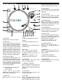
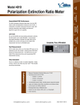
ST.15O DIGITAL TURNTABLE
OWNER S MANUAL
IMPORTANT SAFETY INSTRUCTIONS
1.
2.
3.
4.
5.
Read these Instructions – All the safety and operating instructions should be read before this product is operated.
Keep these Instructions – The safety and operating instructions should be retained for future reference.
Heed all Warnings – All warnings on the appliance and in the operating instructions should be adhered to.
Follow all Instructions – All operating and use instructions should be followed.
To reduce the risk of fire or electric shock, do not expose this apparatus to rain or moisture. The apparatus shall not
be exposed to dripping or splashing and that no objects filled with liquids, such as vases, shall be placed on the
apparatus.
6. Carts and Stands – The appliance should be used only with a cart or stand that is recommended
by the manufacturer.
An appliance and cart combination should be moved with care. Quick stops, excessive force, and
uneven surfaces may cause the appliance and cart combination to overturn.
7. Wall or Ceiling Mounting – The product should be mounted to a wall or ceiling only as recommended by the
manufacturer.
8. Heat – The appliance should be situated away from heat sources such as radiators, heat registers, stoves, or other
appliances (including amplifiers) that produce heat.
9. Power Sources – This product should be operated only from the type of power source indicated on the
rating label. If you are not sure of the type of power supply to your home, consult your product dealer or
local power company. For products intended to operate from battery power, or other sources, refer the
operating instructions.
10. Grounding or Polarization – This product may be equipped with a polarized alternation-current line plug (a plug
having one blade wider than the other). This plug will fit into the power outlet only one way. This is a safety feature. If
you are unable to insert the plug fully into the outlet, try reversing the plug. If the plug should still fail to fit, contact
your electrician to replace your obsolete outlet. Do not defeat the safety purpose of the polarized plug.
11. Power-Cord Protection – Power-supply cords should be routed so that they are not likely to be walked on or pinched
by items placed upon or against them, paying particular attention to the cord in correspondence of plugs,
convenience receptacles, and the point where they exit from the appliance.
12. Cleaning – The appliance should be cleaned only as recommended by the manufacturer.
Clean by wiping with a cloth slightly damp with water. Avoid getting water inside the appliance.
13. For AC line powered units – Before returning repaired unit to user, use an ohm-meter to measure from both AC plug
blades to all exposed metallic parts. The resistance should be more than 100,000 ohms.
14. Non-use Periods – The power cord of the appliance should be unplugged from the outlet when left unused for a long
period of time.
15. Object and Liquid Entry – Care should be taken so that objects do not fall and liquids are not spilled into the
enclosure through openings.
16. Damage Requiring Service – The appliance should be serviced by qualified service personnel when:
A. The power-supply cord or the plug has been damaged; or
B. Objects have fallen, or liquid has been spilled into the appliance; or
C. The appliance has been exposed to rain; or
D. The appliance does not appear to operate normally or exhibits a marked change in performance; or
E. The appliance has been dropped, or the enclosure damaged.
17. Servicing – The user should not attempt any service to the appliance beyond that described in the operating
instructions. All other servicing should be referred to qualified service personnel.
18. Ventilation – Slots and openings in the cabinet are provided for ventilation and to ensure reliable operation of the
product and to protect it from overheating, and these openings must not be blocked or covered. The openings
should never be blocked by placing the product on a bed, sofa, rug, or other similar surface. This product should not
be placed in a built-in installation such as a bookcase or rack unless proper ventilation is the manufacturer’s
instructions have been adhered to.
19. Attachments – do not use attachments not recommended by the product manufacturer as they may cause hazards.
20. Accessories – Do not place this product on an unstable cart, stand, tripod, bracket, or table. The product may fall,
causing serious injury to a child or adult, and serious damage to the product. Use only with a cart, stand, tripod,
bracket, or table recommended by the manufacturer, or sold with the product. Any mounting of the product should
follow the manufacturer’s instructions, and should use a mounting accessory recommended by the manufacturer.
IMPORTANT SAFETY INSTRUCTIONS
21. Lightning – For added protection for this product during a lightning storm, or when it is left unattended and unused for long
periods of time, unplug it from the wall outlet and disconnect the antenna or cable system. This will prevent damage to the
product due to lightning and power-line surges.
22. Replacement Parts – When replacement parts are required, be sure the service technician has used replacement parts
specified by the manufacturer or have the same characteristics as the original part. Unauthorized substitutions may result
in fire, electric shock, or other hazards.
23. Safety Check – Upon completion of any service or repairs to this product, ask the service technician to perform safety
checks to determine that the product is in proper operating condition.
CAUTION
CAUTION: To reduce the risk of electric shock, do not
remove any cover. No user-serviceable parts inside.
Refer servicing to qualified service personnel only.
The lightning flash with arrowhead symbol within the equilateral triangle is intended to alert the
use to the presence of un-insulated “dangerous voltage” within the product’s enclosure that
may be of sufficient magnitude to constitute a risk of electric shock.
The exclamation point within the equilateral triangle is intended to alert the user to the
presence of important operation and maintenance (servicing) instructions in the literature
accompanying this appliance.
CAUTION
To prevent electric shock, do not use this polarized plug with an extension cord, receptacle or other outlet
unless the blades can be fully inserted to prevent blade exposure.
•This device complies with Part 15 of the FCC Rules Operation is Subject to the following two conditions (1) This device may
not Cause harmful interference, and (2) this device must accept any Interference received. Including interference that may
cause Undesired operation.
•This Class B digital apparatus meets all requirements of the Canadian Interference-Causing Equipment Regulations.
•Unauthorized modification of this unit may cause it to no longer comply with FCC regulations and void your authority to use
this device.
•Cet appareil numérique de la classe B respecte toutes les exigencies du Rèsur le materiel brouilleur du Canada.
ASSEMBLY
Remove all the parts from the box. Please check to make sure the
following items are included with the main unit in the carton:
(1)
(2)
(3)
(4)
(5)
(6)
(7)
(8)
(9)
Platter
Slip mat
Counterweight
45-rpm adapter
680HP Cartridge and Headshell
AC cord
RCA cable
Target light
Operating instructions
CONNECTIONS
1. Connect the power cord to an AC outlet.
2. Connect the RCA cable to the PHONO input of your mixer. You can
also use a line input by setting the phono/line switch at the rear of the
turntable to Line.
Note: This turntable has separate analog and digital circuits. If you are
looking for a purely analog signal, use the Phono output. For access to
the Key correction feature use the Line output or S/P DIF output.
TONE ARM AND CARTRIDGE SETTINGS
The major cause of problems in sound and skipping on the vinyl is the
lack of proper set up of the needle and turntable adjustments. The needle
is designed to operate at a specific angle to the vinyl. The ST-150 has
several adjustments to correctly position the needle to the vinyl.
The first adjustment is the correct installation of the cartridge.
Your cartridge is to be mounted into the headshell as pre the mounting
instructions included with the cartridge. The Stanton 500,680 and 890
series of cartridges require the use of the two screw mounting into the
headshell. For your convenience, some of these products can be
purchased already mounted and pre-adjusted from your local Stanton
dealer. If you are using these 1/2” mounted products with a headshell in a
mobile application or you are doing heavy scratching, May want to use an
extra shell weight. The Master series of products (Trackmaster,
Groovemaster, etc.) are designed with their own mounting that eliminates
the need for a separate headshell and the wiring to the cartridge.
The body of the cartridge should be parallel with the centerline of the
headshell-tone arm, when viewed from the front to the back.
The second adjustment is at the installation of the
cartridge-head-shell assembly into the tone arm tube lock. Holding
the tone arm tube in one hand, insert the cartridge-headshell into the tube
lock with the other hand. Turn the lock ring clockwise (when viewed from
the rear) until the headshell is locked tightly into the tone arm. Remove
the needle protector from the cartridge and place the needle on record.
View the needle from the front and insure that the needle is perpendicular
to the record surface. If some adjustment is needed, simply loosen the
lock ring and rotate the cartridge-headshell until the needle is
perpendicular to the record surface. Then re-tighten the lock ring.
The third adjustment is the needle (or stylus) pressure. Start with the
cartridge-headshell assembly mounted into the tone arm. Remove any
needle protectors provided. With tone arm free, adjust the tone arm
counterweight by rotating the rear section until the tone arm floats in a
balanced condition above the record or mat. Do not allow the needle to
drop onto the mat or the turntable platter during this adjustment. You
might damage the needle tip. Now, carefully hold the tone arm in one
hand while rotating the numbered ring on the front of the counter-weight
with the other hand to the “0” setting. Next, without touching the
numbered ring, Rotate the rear counterweight until the desired needle
pressure reading is next to the line on top of the tone arm tube, See the
instructions. Included with your cartridge for proper settings.
The fourth and last adjustment is that of the tone arm height. This
will set the tone arm pivot and needle relation with the vinyl. Unlock the
tone arm base located in the base of pivot assembly. Rotate the height
adjust ring in the pivot base to read the correct setting for the height
adjust ring in the pivot base to read the correct setting for the height of
the cartridge that you are using. Check the cartridge/arm height table for
the correct setting. Be certain to re-lock the pivot base when adjustment
is completed.
PART NAMES & FUNCTIONS
22
21
20
19
the stylus onto the record as it may cause
damage to the diamond tip and to the record.
18
1
17
16
15
14
2
13
12
3
11
1
4
1) START/STOP
Press this button to start or stop the platter.
2) STROBE DOTS
The dots around the edge of the platter are
used in conjunction with the light located inside
the motor ON/OFF switch. While the platter is
in rotation, the dots help to indicate the speed
of rotation. The speed is lower than the
displayed speed (33,45,78) when the dots are
flowing to the right. It is higher than the
displayed speed (33,45,78) when the dots are
flowing to the left. When the strobe is stopped,
the platter is rotating at the displayed speed.
3) MOTOR ON/OFF SWITCH
As opposed to fully analog turntables, this is
not the power switch. This switch only turns on
or off the motor. Rotate clockwise to turn on the
motor. The platter will not start spinning until
the start/stop button has been pressed. Rotate
counter-clockwise during playback (off position)
for a slow winding down effect.
4) PLATTER REVOLUTION SPEEDS (rpm)
33 rpm - Press 33
45 rpm - Press 45
78 rpm - Press 33 and 45 buttons
simultaneously. To return to 33 or 45-rpm play
mode, just press the desired button.
5) TARGET LIGHT
Insert target light to the deck and it will light
up..
5
6
7
8
9 10
6) START
The Start time is adjustable from 0.2~6 sec.
7) BRAKE
The Brake time is adjustable from 0.2~6 sec.
8) REVERSE
This button is used to reverse the direction of
the platter rotation.
14) PITCH ON/OFF
The ON setting will allow use of the pitch adjust.
When set of OFF, the pitch control will be
locked at 0%.
15) TONE ARM BASE
The tone arm base includes the height
adjustment and tone arm rest. See ìtone arm
and cartridge settingsî for proper adjustments.
16) ANTI SKATE KNOB
When a record is playing, a force is generated
drawing the stylus towards the center of the
record. Set this knob to the same value as the
stylus pressure to offset this force.
17) COUNTERWEIGHT
Use this to balance the tone arm and to adjust
the stylus pressure. See ìtone arm and
cartridge settingsî for proper adjustments.
18) LINE OUT L & R
This is the standard analog output (RCA jacks)
which can be connected either to a phono or
line input on any DJ mixer, depending on the
setting of the phono / line selector.
Note: Key lock processing is only
available when the LINE output is used.
19) PHONO/LINE SWITCH
Note: Key lock and Digital output
processing is only available when the LINE
output is used.
9) KEY LOCK
Press to enable key lock. When key
lock is on, the pitch slider will only affect
the speed of the platter. The key (tone) will
remain at 0%
Note: Key lock processing is only
available when the LINE output is used.
20) DIGITAL OUT
Use this output to connect your ST-150 to any
SPDIF in equipped digital device such as a
CD-R or Computer.
10) PITCH SELECT
Press the button to switch between +/-8%,
+/-25%, or +/-50% pitch range.
22) POWER SWITCH
This switch turns the power on or off, including
the motor and audio signal.
11) HEADSHELL LOCKING NUT
Attach the headshell by inserting into the front
end of the tone arm. Turn the locking nut
clockwise with the head shell firmly held
horizontally.
12) PITCH SLIDER
The pitch slider is used to speed up or slow
down the turntable platter.
13) TONE ARM
This is a fully manual tone arm. To start
playback, gently place the stylus on the record
using the headshell finger support. Do not drop
21) POWER CORD CONNECTOR
Used to connect the included power cord.
SPECIFICATIONS
TURNTABLE SECTION
Starting Torque:
Motor:
Platter:
Pitch:
Brake:
TONE ARM SECTION
Tone arm type
Effective Arm Length
Tracking Force Adjust Range
Applicable Cartridge Weight
Frequency Response
Channel Separation
Channel Balance
Wow & Flutter:
S/N ratio:
Needle Pressure range
GENERAL SPECIFICATIONS
Dimensions:
Weight:
Power supply:
Power consumption:
More than 4.5kgf.com
16pole, 3phase, brushless DC motor
332mm dia. Aluminum diecast
+/-8%,+/-25%,+/-50%
Electronic Brake
Static balanced S -shaped tonearm
straight with detachable headshell
230mm
0-3g
13-18g
20 - 20 KHz
More than 15 dB
Within 2.5dB at 1 KHz
Less than 0.1% WRMS
(JIS WTD) with 33 1/3rpm
More than 60dB (DIN-B)
2-5g
450(W) x 353 (D) x 146 (H)mm
16.4Kg
Single Voltage:
AC 100V, 50Hz (For Japan)
AC 110V, 60Hz (For Taiwan)
AC 120V, 60Hz (For U.S.A.,Canada,Mexico)
AC 220V, 50Hz (For United Arab Emirates,Chile,Argentina)
AC 220V, 60Hz (For Philippines)
AC 230V, 50Hz (For Europe,New Zealand,South Africa,Singapore,Israel)
AC 240V, 50Hz (For Australia,U.K.)
14W
Stanton Magnetics, Inc. – Warranty Provision – Returns for Repairs or Replacement
WARRANTY
Through Stanton’s authorized dealers around the World, Stanton, or one of Stanton’s authorized distributors outside the U.S.,
will, without charge, repair or replace, at the sole discretion of the entity responsible for making the repair or providing the
replacement, any Stanton merchandise proved defective in material or workmanship for a period of one (1) year following the
date of original purchase. Exceptions to this warranty are as noted below:
The warranty for mechanical parts which are subject to wear and tear are limited to the earlier to occur of thirty (30) days
following the date of original purchase or the following number of cycles: Faders - 15,000; Rotary potentiometers - 10,000; and
Switches - 10,000.
Stanton will warrant all replacement parts and repairs for ninety (90) days from the date of original shipment. Repairs made
necessary by reason of misuse, alteration, normal wear, or accident are not covered under this warranty.
RETURNS
Authorized Stanton dealers are only authorized to sell and distribute merchandise within a specific country. All goods requiring
warranty repair or replacement must be returned (freight prepaid if not hand-delivered) to the authorized Stanton dealer from
whom the merchandise was purchased and in the same country where the merchandise was purchased. For purposes of
purchases made via the Internet, the merchandise must be returned to the authorized Stanton dealer in the country where the
authorized Stanton dealer which sold the merchandise to purchaser is located and not the authorized Stanton dealer in the
country where the purchaser is located or the country in which the merchandise was received. Any returns to a non-authorized
dealer or to an authorized Stanton dealer not in the same country as the merchandise was intended to be sold or as set forth
above will void this warranty.
To initiate a warranty repair, you must contact the authorized Stanton dealer from whom you purchased the merchandise, and
follow such authorized Stanton dealer’s return policy.
Stanton assumes no risk and shall be subject to no liability for damages or loss resulting from the specific use or application
made of the merchandise. Stanton's liability for any claim, whether based on breach of contract, negligence, infringement of any
rights of any party, or product liability, and relating to the merchandise shall not exceed the price received by Stanton from your
purchase of such merchandise. In no event will Stanton be liable for any special, incidental or consequential damages (including
loss of use, loss of profit and claims of third parties) however caused, whether by the negligence of Stanton or otherwise. To the
extent permitted by law and except as otherwise provided above, Stanton disclaims any express or implied warranties of
merchantability or fitness for a particular purpose.
The above warranty provides you with specific legal rights. You may also have additional rights, which are subject to variation
from state to state and country to country.
If there is a dispute regarding the warranty of merchandise that does not fall under the warranty conditions stated above, please
include a written explanation with the merchandise when returned pursuant to the terms and conditions set forth herein.
Please register your product online at www.stantondj.com or mail your completed warranty card to:
Stanton Magnetics, Inc, 3000 SW 42 St. Hollywood, Florida 33312.
Ground lift Operation
Due to the variety of power sources available to the DJ, Stanton has included a
ground lift switch to be used on the ST- 150/STR8-150 turntables. This will allow
the DJ to have the capability of changing the grounding scheme of the phono
cartridge to avoid ground hum that may occur when using the turntable. The ST150/STR8-150 Turntable has been designed to operate with third pin safety ground,
and should always be used when available. N E V E R R E M O V E T H I R D P I N
GROUND FROM THE POWER CORD PROVIDED, IF NECESSARY,
USE THE APPROPRIATE ADAPTER FOR PLUGGING INTO OUTLETS
WHICH DO NOT PROVIDE THIRD PIN GROUND TERMINALS.
For best operation of the ground lift, the following rules should be applied
W h e n t h i r d p i n s a f e t y g r o u n d i s u s e d , set the ground lift switch to the lift
position. This position will isolate the cartridge ground from connection to earth
ground.
When third pin safety ground is unavailable, set the ground lift switch to the
connected position. This will place the cartridge ground in connection with the
chassis ground, but since third pin grounding is not used, the cartridge ground will
not be in connection with earth.
cut along dotted line
State
Where did you buy this product?
Date of Purchase
Serial Number
Model Number
PRODUCT INFO
Telephone
Country
City
Address
Name
PERSONAL INFO
Zip
If you have internet access, please register your product at
www.stantondj.com. Otherwise, return this card completely filled
out in order to validate your warranty.
STANTON WARRANTY REGISTRATION CARD
PLACE
STAMP
HERE
Stanton Magnetics, Inc.
3000 SW 42nd Street
Hollywood, FL 33312
U.S.A.