1
Connecting keyboards
Keyboard switches are connected to 2 keyboard interfaces
(J1 and J2) and with optional keyboard scanners, or in
another words - expander boards, which is described in
Expanders section later in this manual.
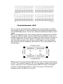
Two onboard 8x8 scanner drivers can be used if the
keyboard has “scanning diode matrix”, that's simple circuit,
made of diodes forming electric XY array of 8 rows and 8
columns. Usually all modern keyboards are equipped with it.
In fact it is integral part of the contacts board found beneath
the keys. Those kind of keyboards can work directly with
MIDI128 controller, as well as optional DMS-2K scanner.
Older keyboards, and especially those used in old analog
organs, usually don't have such a thing, so in order to use
8x8 scanner, you must solder the diodes to your contacts,
according to schematics on the right.
Table below shows scanner needed for different keyboards:
Keyboard type
MIDI128
DMS-2K
Independent switches, no
◊
connection to any circuitry
Switches organized in 8x8
●
matrix, with diodes
Switches organized in 8x8
◊
matrix, no diodes
Switches 5x12 and other
(Yamaha, Casio)
One common rail for all
switches
BBS
PEDSCAN
●
◊
‡
●
‡
◊
‡
●
● - can be used directly
◊ - with external diode matrix
‡ - some rewiring of original contacts circuit may be required
On the MIDI128 controller, as well as DMS-2K expander,
each 16-way connector covers one keyboard.
Schematic on the right side of this page shows
compatible diode matrix.