1
Connecting potentiometers
Pot inputs can be used as continuous controllers for things like volume, modulation
etc. Usually those inputs would be connected to potentiometers, but it's possible to
use them as analog inputs with range of 0..+5V. Applying voltage of 0V causes
MIDI128 to generate CC with lowest value, while +5V generates highest possible
value of assigned MIDI parameter. There are 8 available inputs, 7 of them user
configurable in terms of controller type and MIDI channel. Potentiometers are
connected to 1 smaller black connector (J7). 8th input (pin 10) is dedicated for
MIDI notes velocity setting. Below is schematic of potentiometers connections:
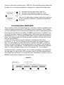
The pinout for J7 is as follows:
–
–
–
–
1 Vcc, connect to upper terminal of all 8 pots
2 GND, connect to lower terminal of all pots
3-9 CC inputs, connect wiper terminals of CC pots
10 velocity input, connect wiper of the pot controlling notes' velocity
If you don't use all 8 potentiometers, it is recommended to connect unused inputs
to VCC (pin 1 of J7). It's quite safe to leave them open, but in some cases it may
result in unwanted MIDI CC messages. The potentiometers must be linear taper
(non audio). Recommended resistance value is 10-50kohms.
Special functions
There can be numerous features ordered, but standard set is just transposition and
channel change. All of them are available on small 10-pin connector marked as J6
in the layout diagram. They are organized as follows:
2
GND
1
VCC
4
transpose +1
3
transpose -1
6
octave +1
5
octave -1
8
channel +1
7
channel -1
10
prog. ch. +1
9
prog. ch. -1
This is the look of the pins if the J6 was rotated left by 90 deg. from position shown
in the layout diagram. The numbers in this table correspond with wire number if
standard flat cable with IDC plug is used