1
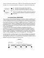
connect it with main controller board - MIDI128. The same diode matrix boards can
be used. Go to “Connecting keyboards” paragraph for details about diode matrix.
J1 – connector of 1st group of keys (1 to 64)
J2 – connector of 2nd group of keys (65 to 128)
J3 – connector linking this board with the main board
Close to J3 is little activity indicator, that blinks every time
a note is played or released in a keyboard connected to
this board
32 and 64 keys scanner - BBS64X, BBS32X
There's another family of keyboard scanners, especially suitable for keyboards with
single rod used as common bus for all switches in entire keyboard. This one does
not use diode matrix, and can be used with almost any type of switch arrangement,
it can also be controlled by logic gates. The BBSX boards come in 2 variants. They
can work with either positive or negative keying, which means that key pressed is
represented by 0V, or +5V, but proper BBS version must be selected when placing
order. The board can have less 16-pin connectors available, covering only 32 keys.
It's then called BBS32X.
In case of the big, 64-keys version, keyboard is connected to four 16-pin
connectors - J1, J2, J3 and J4 shown on the next page. Each of them covers 16
keys. The key contacts can have one common buss bar (with GND), or it can be
driven from logic IC outputs. 0V at an input means “key pressed”, +5V at input or
left open means “key released”. The BBS board can be also ordered with reversed
logic, i.e. positive voltage at input means “key pressed”, 0V - “key released”.
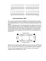
Keyboard should be connected to four 16-pin headers according to the diagram on
the next page. It's best to use 4 IDC connectors and 16-wire flat computer grade
cable. Each cable connects to 16 consecutive keys. Connection of all keys to pins in
BBS64X is also shown in diagram on the next page.
LAYOUT