1
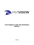
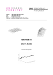
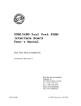
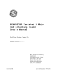
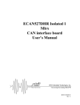
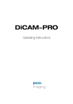
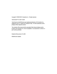
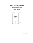
FASTCAMERA DVRP-VS
USER’S MANUAL
FVM-00400
1
COPYRIGHT NOTICE
Copyright © 2004 by FastVision LLC.
All rights reserved. This document, in whole or in part, may not be copied, photocopied,
reproduced, translated, or reduced to any other electronic medium or machine-readable form
without the express written consent of FastVision LLC.
FastVision makes no warranty for the use of its products, assumes no responsibility for any error,
which may appear in this document, and makes no commitment to update the information
contained herein. FastVision LLC. retains the right to make changes to this manual at any time
without notice.
Document Name:
FastCamera-DVRP User’s Manual
Document Number:
FVM-00400
Revision History:
1.0
July 29, 2004
Trademarks:
FastVision® is a registered trademark of FastVision LLC.
Channel Link™ is a trademark of National Semiconductor
Virtex™ is a trademark of Xilinx Inc.
Windows™, Windows 95™, Windows 98™, Windows 2000™, Windows NT™, and
Windows XP™ are trademarks of Microsoft
Video Savant, DVR Express, CL160 are registered trademarks of IO Industries.
All trademarks are the property of their respective holders.
FastVision LLC.
131 Daniel Webster Highway, #529
Nashua, NH 03060
USA
Telephone: 603-891-4317
Fax: 603-891-1881
Web Site:
http://www.Fast-Vision.com/
Email:
[email protected], or [email protected]
2
TABLE OF CONTENTS
HARDWARE
INSTALLATION…………………………………………………………………………5
OPEN SYSTEMS CHASSIS.......................................................................................................5
INSTALL DISK RACKS .............................................................................................................5
INSTALL BOARDS ....................................................................................................................7
REPLACE THE SIDE PANEL ....................................................................................................7
CONNECT FASTCAMERA TO FRAMEGRABBER..................................................................7
CONNECT THE PC CABLES: KEYBOARD, MOUSE, VIDEO DISPLAY, ETHERNET, AND
POWER.......................................................................................................................................7
INSTALLING FASTCAMERA-DVRP APPLICATION ...............................................................7
SETTING UP SCSI RAID DISK ARRAY....................................................................................8
CREATING AND EDITING CAMERA FILES ............................................................................9
VIDEO ACQUISITION AND DISPLAY.....................................................................................11
CREATING AND MANAGING VIDEO FILES..........................................................................13
FASTCAMERA CONTROL PROGRAM ..................................................................................15
VIDEO PLAYBACK AND STREAM PROCESSING ...............................................................18
ARCHIVING AND EXPORTING VIDEO DATA .......................................................................18
TROUBLESHOOTING .............................................................................................................23
FASTVISION TECHNICAL SUPPORT ....................................................................................24
CONTACTING TECHNICAL SUPPORT .................................................................................24
3
OTHER MANUALS
IO Industries manuals cover all aspects of CL160 hardware and software installation and
operation.
Call FastVision at 603-891-4317 and request the appropriate manuals from the list below if they
did not come in your FastCamera –DVRP shipment.
[1] Video Savant User’s Guide, Version 4.0
[2] DVR Express Digital Camera Interface and Recorder
[3] FVM-00400 FastCamera-40 User’s Manual
4
INTRODUCTION
This manual covers the FastVision, LLC FastCamera-DVRP system and software. It covers
hardware and software installation, systems configuration and application controls.
Proper operation of the FastCamera-DVRP relies on carefully selected hardware components
integrated in a well balanced computer system. Achieving the high sustained digital video rate
heavily depends on underlying hardware configuration. Generally, such a computer system is
classified as a computer server. It is recommended that no other computer or data movement
applications are running during video capture operations.
FASTCAMERA-DVRP SYSTEM
The FastCamera-DVRP is a digital recording system that is based on the FastVision FastCamera
connected by one standard CameraLink cable to the IO Industries CL160 framegrabber. The
CL160 framegrabber has direct connection to the RAID-0 array of SCSI hard disks.
Video data recording and playback is controlled by the Video Savant application that works under
Windows 2000 operating system. The FastCamera-DVRP system enables recording of video
captured by a FastCamera at the rate of 80 MB/sec for up to 40 minutes.
The FastCamera-DVRP also allows offline video playback and processing of image files that
were recorded by the FastCamera-DVRP system including exporting single frames and groups of
frames to standard image.
HARDWARE INSTALLATION
**NOTE: Hardware components of the FastCamera DVRP system are very sensitive to the
electrostatic discharge (ESD) and there can be irreversible damaged by improper
handling. Persons performing hardware installation should use a grounding strip and
strictly follow proper ESD procedures.
The following components of the FastCamera-DVRP are removed for shipment and must be
installed back in the system before first use in the listed order:
• SCSI and IDE disk racks,
• AGP8 graphics card,
• CL160 framegrabber board,
• SCSI cable,
• FastCamera cable,
• FastCamera power supply and cable
OPEN SYSTEMS CHASSIS
Remove screws holding side panel of the chassis closest to the fans in the back, slide the panel
out and put it away protecting from scratches and warping. The side panel should be replaced at
the end of the hardware installation procedure.
INSTALL DISK RACKS
•
Slide IDE disk rack in the upper and SCSI disk rack in the lower positions as depicted
below. Connect the IDE and power cable.
•
Before installing the SCSI rack, connect the terminated end of an LVDS SCSI cable to
the top disk in the SCSI rack and attach the two following connectors to the
corresponding disks as in the picture below. Be careful to thread the SCSI rack’s fan
5
power cord through the rack’s socket so it will not be pinched between the socket and the
rack.
•
Push locking level of each rack toward the front of the chassis until it locks.
•
Connect chassis power connectors to each disk and to the special power connector of
the lowest SCSI disk that feeds the SCSI rack fan.
IDE rack
AGP Graphics card
SCSI
rack
CL160 framegrabber
Fan Power cable
Special power
connector
Figure 1. FastCamera-DVRP chassis
6
INSTALL BOARDS
•
•
•
Place AGP8 graphics card in the AGP slot on the motherboard and affix rear bracket with
a screw.
Insert CL160 framegrabber board in the lowest PCI slot farthest from the AGP slot and
screw the rear bracket to the chassis.
Connect un-terminated end of the LVDS SCSI cable from the SCSI disk rack to the
internal SCSI connector on the CL160 board.
REPLACE THE SIDE PANEL
Reverse steps taken to open DVRP system chassis in the section above.
CONNECT FASTCAMERA TO FRAMEGRABBER
Connect a Camera Link cable to the rear bracket connector on the CL160 framegrabber board
and to the Camera Link connector on the back of FastCamera.
Connect FastCamera power cable to the round connector on the back of the FastCamera and
plug power cord in the FastCamera power adapter. The LED light on the adapter should glow
green when AC power is turned on.
CONNECT THE PC CABLES: KEYBOARD, MOUSE, VIDEO DISPLAY,
ETHERNET, AND POWER.
SOFTWARE INSTALLATION
INSTALLING FASTCAMERA-DVRP APPLICATION
The FastCamera-DVRP application includes drivers for the CL160 framegrabber, the DVR Disk
Manager, the Camera File Editor, the Video Savant recording and playback application and the
FastCamera Control Program. All these software components are installed from two CD-ROM
disks in two steps, first – the Video Savant 4.0 software, then Video Savant update and the
FastCamera Control Program.
In order to install the FastCamera-DVRP application software:
• Attach the Parallel Port protection key to the parallel port in the back of the chassis.
• Insert the Video Savant 4.0 installation CD-ROM into your CD-ROM drive.
• Access your CD-ROM drive, go to ”..\VSAVANT” directory and double click “setup.exe” .
• Follow the on-screen instructions to install Video Savant application and the Security
Key.
• After the installation is complete, reboot the PC System to complete the software
installation and the environment setup.
• Insert CD-ROM-2 with the Camera Control and Video Savant update CD-ROM into your
CD-ROM drive.
• Go to CD-ROM-2\CameraControl directory and click “setup.exe”.
• Go to the top of CD-ROM-2 and click on “vs4sp8b.exe”
• Copy CD-ROM-2\CAMFILES to C:\VSAVANT4\CL160\CAMFILES.
• Copy file CLSERIOI.DLL from the top folder of CD-ROM-2 to c:\WINNT\system32
• Reboot the DVRP system.
7
FASTCAMERA-DVRP OPERATION
OVERVIEW
This chapter focuses on essential tasks necessary to capture, display and manage video data
using FastCamera-DVRP system, namely:
•
•
•
•
•
•
pre-configuring DVRP system for video data acquisition by creating a set of Video Files
on the RAID disk array,
recording captured video data in Video Files,
setting up conversion of raw video data from Bayer filter format to RGB,
playing back and analyzing captured video data,
managing Video Files,
Exporting video images from the internal format of Video Files to standard image formats,
and importing standard format images into Video Files.
The six major components of the FastCamera-DVRP system are:
•
•
•
•
•
•
The FastCamera
The fast SCSI RAID disk array preserving captured and processed video data
A Video File allocated on the SCSI RAID array to hold a particular set of video data
A Camera File that defines permanent characteristics of the FastCamera used in
acquiring video data for the Video File
The FastCamera Control Program adjusting exposure and frame rate for video
acquisition
All other PC resources
Large number of streaming filters is included with application to perform assorted image
processing tasks, including conversion of raw Bayer filter images into the full color images,
performing geometric transformations, measuring image parameters, importing and exporting
images from the internal, raw format into standard image formats like TIFF and AVI.
The Video Savant SDK included in the FastCamera-DVRP package equips user with examples
and collection of DLL libraries with full C++ source code simplify addition of user-written plug-in
filters. Other similar filters can be developed in C/C++ or Visual Basic.
The full manual set includes the Video Savant User’s Guide and the DVR Express Product
Family User’s Guide that provide extensive coverage for more in-depth subjects like working with
multiple Video Files, Image Processing and Analysis, and for developing custom solutions using
Video Savant SDK.
SETTING UP SCSI RAID DISK ARRAY
The fast SCSI RAID disk array is essential for video data capture at high resolution and high
sustained frame rates. It must be created and configured before all other activities can proceed.
The main tool in that process is called Disk Manager. It performs two basic operations: writing
disk signatures and creation of Disk Array on the set of connected SCSI disk drives. Disk
Manager’s additional capabilities include deleting Disk Arrays and repairing damaged ones. Its
operations are simple and straightforward. The DVRP system administrator should start Disk
Manager and follow its directions. See its main dialog box in the picture below showing creation
of a single Disk Array out of three SCSI disks.
8
Figure 2. Creating RAID disk array in DVR Express Disk Manager
CREATING AND EDITING CAMERA FILES
A camera file describing format and parameters of the output signal from a camera is another
essential prerequisite for video data capture. Each Video File on the RAID disk array is tightly
bound to a camera file. Once camera file information is stored with a Video File, it can not be
changed, except by deleting and re-creating new Video File. Changes in a camera file made after
creation of a Video File will not make any difference. The FastCamera-DVRP system comes with
a full set of camera files describing FastCamera-40 and FastCamera-13 with black and white and
with color sensors:
Figure 3. Selecting Camera File
9
A camera file only describes FastCamera output signal. It doesn’t change or set the camera to
work in that mode. For video capture to work, the FastCamera must be configured into a
corresponding mode by the FastCamera Control Program. Video capture will not work if there is
a mismatch between camera definition memorized by a Video File and the actual FastCamera
operating mode.
A match between the Video File description and actual camera settings can be easily verified by
testing the camera file in the live video test. The user can open an existing camera file and click
Test Live in the resulting dialog box:
Figure 4. Testing Camera File with live video
An Image Display Area will show monochrome rendering of the raw captured video if settings do
match. No image data conversion will be used in the process. Capture of the Live video data
must be stopped by clicking Stop Live in order to make changes in the camera file.
One important parameter in a camera file conveys the presence of Bayer color filter in the
camera and thus warns acquisition software of a Bayer pattern structure of the camera output
signal. That structure allows recovery of color information and the mark triggers automatic use of
Bayer conversion filter when recorded video data are being played back, processed or exported.
Configuring such Bayer-to-RGB conversion filter using white balance is subject of a separate
treatment in a section below.
Figure 5. Marking camera as Bayer Filter color type
If changes have been made in the camera file during testing with the Camera File Editor, the user
will be asked to confirm saving these changes in the original camera file on exit from Program.
These changes will affect only Video Files
10
VIDEO ACQUISITION AND DISPLAY
The Video Savant application controls all operations of the FastCamera-DVRP system that deals
with capturing and replaying of video data. Immediately upon starting the Video Savant
application the users will see its work area. It consists of a large Image Viewing Area and
adjacent Control Panel: a large main window that can be positioned anywhere in the system
window. The Image Display Area displays video captured by the camera or stored in the RAID
array. Multiple control panels can be added to main window for access to the most often used
controls for capture and playback operating modes.
Image Display Area
Control Panel
Figure 6. Video Savant work area
All operations are centered on a primary Video File and Video Savant is useless until such file is
specified. The Video Savant memorizes primary Video File between sessions and automatically
restores capture parameters associated with that file every time application is started.
The Image Display Area works in two distinct modes: a single frame view as above and as a
multiple frames view (or thumbnail view) below.
11
Figure 7. Video Savant work area with thumbnail images
One of the most important properties of the Image Display Area is the handy Quick Menu
feature activated by a single right-mouse button click in the Area. The Quick Menu controls
Image Zoom and Export/Import among other important parameters.
Figure 8. Video Savant Quick Menu
The Quick Menu has different options in single-frame and thumbnail modes. In the single frame
mode Quick Menu supports Select Image Buffer command to image a particular frame. On
the other side, set of frames can be selected in the multiple frames view by using Select Image
Buffer range in the Quick Menu.
12
The User switches between these views by double-clicking left mouse button. Number of rows
and size of thumbnails in the multiple frames view is defined in the Thumbnails panel under
Display tab. The User should exercise caution in selecting the smallest, 32 pixel size: painting
and refreshing Image Display Area can take a really long and annoying -time in that setting.
The Video Savant activities are alternating between two self-descriptive distinct modes: Digital
Video Recording (DVR) or Digital Video Playback. The User can switch between these modes
very quickly and at will as long as they involve the same Video File. Each of these modes can be
additionally configured to support in-line streaming filter image processing and analysis.
Switching between different Video Files, i.e. selecting different Video File as primary will cause
hardware reconfiguration and the application will reboot.
There is significant complexity and richness in activities supported by the Video Savant.
Controlling these activities require navigation through the maze of control panels whose panels
alternate among various optional views. One combined view of all control panels can be seen in
Appendix A as a quick reference to control panels.
CREATING AND MANAGING VIDEO FILES
Depending on the application requirements, the user can treat video storage space provided by
the RAID disk array as a large single Video File or subdivide it in a set of Video Files. Each Video
File will preserve definition of camera settings including (optional) conversion filter and its
settings. In either case navigation inside Video File is done by a frame (image buffer) number.
Each Video File has a predefined number of frames
Advantages of only one Video File at a time can be designated as Primary and displayed in the
Image Display Area. Switching to another Video File causes hardware reconfiguration and
application reboot.
Figure 9. Video File selection
Deleting Video File will not destroy stored video data; they will pop-up in the newly created file if it
overlaps areas used by the deleted file. The User can apply Benchmark/Erase File operation to
completely wipe out old video data and prevent potential future confusion.
13
RECORDING VIDEO DATA
Once RAID disk array is set and primary Video File is selected, the FastCamera-DVRP system is
ready to record captured video data. The User starts by selecting DVR tab on the control panel
that brings DVR Control panel to foreground.
The left side of the DVR control panel of the Video Savant presents all essential recording
controls for the following actions:
•
•
•
•
Invoke dialog box to choose another Video File,
Define appropriate Stopping conditions (recording time or number of frames) for a
recording session,
Have Live video preview to adjust camera targeting and exposure,
Start and Stop actual recording.
Live video preview button toggles between starting and stopping video preview. It also puts
Image Display Area in the single-frame view mode.
Settings in the Display Tab will determine refresh frame rate of Live display during video
recording. The User might consider reducing frame display refresh rate or suspend Live frame
display altogether at higher recording frame rates to reduce memory contention and prevent
potential loss of frames.
Figure 10. DVR recording controls
At the completion of each recording (and playback) session Video Savant displays statistical
summary of the session parameters:
14
Figure 11. Recording session statistics
The error section of this summary will signal potential problems with video capture when
framegrabber hardware fails to keep up with camera video stream.
FASTCAMERA CONTROL PROGRAM
The FastCamera Control Program is necessary to set FastCamera in a mode matching the
camera file and to fine tune exposure and frame rate settings required by an application. Camera
controls are simple and self explanatory. Setting exposure and frame rate controls uses a
combination of slider and scale factor to cover wide range of available values.
Figure 12. FastCamera Control Program
15
The camera setting can be preset ahead of time and saved in one of eight locations in the
camera flash memory simplifying its use. The Index of saved camera settings can be recorded in
the Video File comment area and all necessary settings can be loaded at once in the beginning
of a working session. The FastCamera automatically loads settings from the area 1 at a power
boot time.
16
CONVERTING VIDEO IMAGES FROM BAYER TO RGB
The FastCamera captures color information in images by means of the Bayer color filter
deposited directly on the monochrome video sensor. Each pixel under Bayer filter carries
information only about one color component.
G
R
G
R
G
R
G
B
G
B
G
B
G
R
G
R
G
R
B
G
B
G
B
G
G
R
G
R
G
R
B
G
B
G
B
G
Figure 13. Bayer filter pattern
Images captured and stored in Bayer color format are considered by the Video Savant as a
foreign image format and require conversion to the standard RGB color image by a special
processing stage. Such processing is done inline before video frames are displayed, exported or
processed. An RGB image imported in a Bayer color image video file will be transformed in Bayer
format before storage in the Video File.
Usually Bayer conversion on video data in the Video File is specified directly in the camera file
associated with Video File (see discussion about camera files above).
Alternatively, conversion can be enabled after recording at a playback / processing time by
editing Video File properties, namely, Conversion field:
1
2
3
4
5
6
Right Click
to Complete
Selection
8
7
Figure 14. Configuring Bayer to RGB image conversion
17
The picture above shows all steps involved in defining and balancing Bayer-to-RGB conversion in
the Video File. Once conversion filter is set in the Video File, further adjustments of white balance
can be simplified by going through command sequence: Video File-> Setup Conversion
Filter…->White Balance.
NOTE: Depending on the implementation, speed of a Bayer-to-RGB conversion filter can
restrict playback speed.
VIDEO PLAYBACK AND STREAM PROCESSING
Playback of captured video data stored in the active Video File can be started at any time when
video recording or preview is stopped. Playback starts at position in the active Video File where it
was left by previous operation. This position can be changed by two methods:
•
•
Entering desired frame number directly in the Image Buffer edit box
Dragging slider control to the desired place in the record (Images of frames will pass in
the Image Display Area after a second delay if conversion filter is enabled)
Figure 15. DVRP playback controls
ARCHIVING AND EXPORTING VIDEO DATA
Video data stored in the RAID disk array are readily available to the Video Savant application
program but invisible to Host computer and its operating system and Host applications. If the
user needs to archive recorded data or transport them to a Host-resident application, these data
must be first exported to a Host-visible storage device.
There are two ways to do it:
• Using Quick Menu commands,
• Using Image File Types Control Panel.
The Quick Menu controls export and import of images. The first step in exporting video images
is selecting image set to be exported. By default, selected set includes a frame at the current
frame position in the Video File.
18
1. Invoking Quick Menu in a single-frame view mode designates currently displayed frame
(image buffer) for the export. Imported image will be converted and inserted at a current
frame position in the Video File as well.
2. Using Quick Menu in a multiple-frames view mode presents more options for these
operations. It allows selection of an image set either by the first / last frame numbers, or
by row / column, and even all frames in the file. Conversion will be invoked
automatically if it was defined in the Video File creation.
Figure 16. Selecting images for export
NOTE:
The User should exercise caution in exporting large image sets since
necessary image processing operations, especially conversion, can limit export to a
19
very low frame rates. Exporting tens of thousands of images could take hours and can
consume significant system resources.
Image format of exported files will be determined at the last step of selection:
Figure 17. Selecting image format for exported files
20
21
APPENDIX A – VIDEO SAVANT CONTROL PANELS QUICK REFERENCE
22
TROUBLESHOOTING
There are several things you can try before you call FastVision Technical Support for help.
_____
Make sure the computer is plugged in. Make sure the power source is on.
_____
Go back over the hardware installation to make sure that the system is properly
installed.
_____
Go back over the software installation to make sure you have installed all necessary
software.
_____
Run the Installation User Test to verify correct installation of both hardware and
software.
_____
Run the user-diagnostics test for your main board to make sure it’s working properly.
_____
Insert the FastVision CD-ROM and check the various Release Notes to see if there is
any information relevant to the problem you are experiencing.
The release notes are available in the directory:
C:\Program Files\FastVision LLC\FastViewer-3FF\alinfo
23
FASTVISION TECHNICAL SUPPORT
FastVision offers technical support to any licensed user during the normal business hours of 9
a.m. to 5 p.m. EST. We offer assistance on all aspects of processor board and PMC
installation and operation.
CONTACTING TECHNICAL SUPPORT
To speak with a Technical Support Representative on the telephone, call the number below and
ask for Technical Support:
Telephone:
603-891-4317
If you would rather FAX a written description of the problem, make sure you address the FAX to
Technical Support and send it to:
Fax:
603-891-1881
You can email a description of the problem to
[email protected]
Before you contact technical support have the following information ready:
_____ Serial numbers and hardware revision numbers of all of your boards. This information is
written on the invoice that was shipped with your products.
_____ Also, each board has its serial number and revision number written on either in ink or in
bar-code form.
_____ The version of the ALRT, ALFAST, or FASTCAMERA-DVRP software that you are using.
_____ The type and version of the host operating system, i.e., Windows 98.
_____ Note the types and numbers of all your software revisions, daughter card libraries, the
application library and the compiler
_____ Returning Products for Repair or Replacements
Our first concern is that you be pleased with your FastVision products.
If, after trying everything you can do yourself, and after contacting FastVision Technical Support,
you feel your hardware or software is not functioning properly, you can return the product to
FastVision for service or replacement. Service or replacement may be covered by your warranty,
depending upon your warranty. The first step is to call FastVision and request a “Return Materials
Authorization” (RMA) number. This is the number assigned both to your returning product and to
all records of your communications with Technical Support. When a FastVision technician
receives your returned hardware or software he will match its RMA number to the on-file
information you have given us, so he can solve the problem you’ve cited.
24
When calling for an RMA number, please have the following information ready:
_____
Serial numbers and descriptions of product(s) being shipped back
_____
A listing including revision numbers for all software, libraries, applications, daughter
cards, etc.
_____
A clear and detailed description of the problem and when it occurs
_____
Exact code that will cause the failure
_____
A description of any environmental condition that can cause the problem
All of this information will be logged into the RMA report so it’s there for the technician when your
product arrives at FastVision. Put boards inside their anti-static protective bags. Then pack the
product(s) securely in the original shipping materials, if possible, and ship to:
FastVision LLC.
71 Spit Brook Road, Suite 200
Nashua, NH 03060
USA
Clearly mark the outside of your package:
Attention RMA #90XXX
Remember to include your return address and the name and number of the person who should
be contacted if we have questions.
Reporting Bugs
We at FastVision are continually improving our products to ensure the success of your projects.
In addition to ongoing improvements, every FastVision product is put through extensive and
varied testing. Even so, occasionally situations can come up in the fields that were not
encountered during our testing at FastVision.
If you encounter a software or hardware problem or anomaly, please contact us immediately for
assistance. If a fix is not available right away, often we can devise a work-around that allows you
to move forward with your project while we continue to work on the problem you’ve encountered.
It is important that we are able to reproduce your error in an isolated test case. You can help if
you create a stand-alone code module that is isolated from your application and yet clearly
demonstrates the anomaly or flaw.
Describe the error that occurs with the particular code module and email the file to us at:
[email protected]
25
We will compile and run the module to track down the anomaly you’ve found.
If you do not have Internet access, or if it is inconvenient for you to get to access, copy the code
to a disk, describe the error, and mail the disk to Technical Support at the FastVision address
below.
If the code is small enough, you can also:
FAX the code module to us at 603-891-1881
If you are faxing the code, write everything large and legibly and remember to include your
description of the error.
When you are describing a software problem, include revision numbers of all associated
software.
For documentation errors, photocopy the passages in question, mark on the page the number
and title of the manual, and either FAX or mail the photocopy to FastVision.
Remember to include the name and telephone number of the person we should contact if we
have questions.
FastVision LLC.
131 Daniel Webster Hwy #529
Nashua, NH 03060
USA
Telephone: 603-891-4317
FAX: 603-891-1881
Web site:
http://www.FastVision.com/
Electronic Mail:
[email protected]
[email protected]
26