1
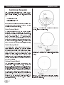
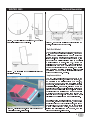
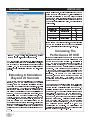
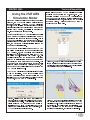
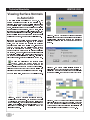
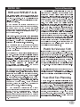
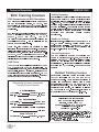
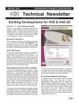
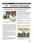
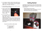
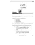
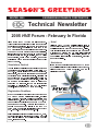
SEASON’S GREETINGS WINTER 2005 ENGINEERING DYNAMICS CORPORATION Technical Newsletter 2005 HVE Forum - February In Florida Plans for the 2005 HVE Forum are fully underway. This event is once again going to raise the bar for user education and experience. If you have never been to a HVE Forum before, you should come and see why the HVE Forum is such a successful event year after year. The 2005 HVE Forum offers workshops for beginning, intermediate and advanced users, in both hands-on and lecture style formats. In addition, the HVE White Paper session, Users Group meetings, and hosted social hours offer a great opportunity to network with other HVE users. Simulations Festival The Simulations Festival is an opportunity to showcase your talent for producing simulation movies using HVE or HVE-2D. Your simulations may be from actual cases, staged tests, or even examples that have been created to contribute to the Simulations Festival. All entries will be compiled onto a DVD which will be played during the 2005 HVE Forum social hours and activities. Prizes will be awarded for simulations voted as winners of categories by attendees. If you are interested in submitting a simulation for the HVE Simulations Festival, please contact EDC Customer Service. Registration Deadlines By now you should have received your copy of the 2005 HVE Forum Workshop Registration booklet, complete with workshop schedule, detailed descriptions and registration form. If you havent received a copy, you can download one directly from the 2005 HVE Forum page of the EDC website. There are links on the EDC website home page to go directly to the 2005 HVE Forum page, or enter this location into your browser: www.edccorp.com/service/hveforum.html. Early registration discounts expire January 15, 2005, but dont wait until the last minute to register. The hotel room block is filling up very quickly and it is on a first come, first served basis. Hotel All of the 2005 HVE Forum activities will take place at the Mayfair Hotel and Spa, a Kimpton brand all-suites hotel located in the heart of Coconut Grove, Florida. This ideal location is just 10 minutes from downtown Miami and 12 minutes from the Miami International Airport and South Beach. Within walking distance of the hotel is a large selection of restaurants, shopping and other activities. Assistance If you have any questions about the 2005 HVE Forum or would like assistance with selecting your workshops, please contact EDC Customer Service. See you in Florida in February! Technical Newsletter WINTER 2005 Technical Session This Technical Session introduces a suite of new tire-terrain models that greatly extend the capabilities for HVE vehicle simulation. The new tire-terrain models are: Ø Radial Spring Model Ø Sidewall Impact Model Ø Soft Soil Model Each of these models can be selected to replace the (default) Point Contact Model and provides a specific capability not previously available. Point Contact Model To better understand how the new models provide additional modeling capabilities, it is useful to understand something about the Point Contact Model. As its name suggests, the Point Contact Model assumes that the tire force, Fx’, Fy’, is a shear force applied at the ground plane at a single point directly beneath the wheel center. This assumption is good for a majority of conditions. In particular, the default model assumes a flat (not necessarily horizontal), rigid terrain. Radial Spring Model The Radial Spring Model models the tire as a series of springs lying in the tire plane and projecting radially outward from the wheel center (see Figure 1). Whereas the Point Contact Model may be thought of as a single spring projecting downward and interacting with the terrain at a single point, the Radial Spring Model provides numerous springs that may interact with multiple surfaces. This model is ideal for simulating tires mounting curbs and rolling over potholes (see Figures 2 and 3, respectively). Sidewall Impact Model The Sidewall Impact Model is an extension of the Radial Spring Model, described above. In the Sidewall Impact Model, each radial spring has additional springs projecting laterally outward from the wheel plane to the tire sidewall plane (see Figure 4 ). This model allows for the first time a rigorous modeling of the force applied to the sidewall of a tire. Because it is not limited by coulomb friction, the sidewall force may be significantly larger than the force at the tire contact patch. This provides a new and important modeling capability. An obvious application is the classic curb-tripped rollover (see Figures 5 and 6). 2 Figure 1 - The Radial Spring Model uses evenly spaced springs, instead of a single spring. Figure 2 - The Radial Spring Model is useful for simulating conditions in which there are multiple tire-terrain contact points. Figure 3 - The Radial Spring Model is also useful for simulating conditions in which the contact point is not directly beneath the wheel center. WINTER 2005 Figure 4 - The Sidewall Impact Model uses 2, 4 or 6 springs projecting laterally from the wheel plane. Figure 5 - The Sidewall Impact Model is ideally suited for simulating curb impact. Technical Newsletter Figure 7 - The Soft Soil Model allows the tire to sink into the terrain, producing a drag force on the tire. Soft Soil Model The Soft Soil Model is based on research performed by M.G. Bekker at the University of Michigan. The purpose of part of the original research was to predict the performance and tractive effort requirements of the lunar rover. In the Soft Soil Model (see Figure 7), tire sinkage into the soil is calculated using an empirical model developed by Bekker. Tire Fx’,Fy’ forces are calculated based on the sinkage. This model is ideal for calculating tire drag for a vehicle that has left the roadway and is traveling though soft dirt. The model is also useful for predicting soil-tripped rollover. Soil coefficients may be provided for individual surfaces using the Environment 3-D Editor. Implementation The new Tire-Terrain option has been added to the Event Editors Wheels Set-up dialog (see Figure 8), as an extension to the existing options (Tire Blow-out, Wheel Damage and Brake). Like the existing options, the new tire-terrain options may be applied separately to individual tires. For example, all tires may use the default point contact model. Alternatively, the left front tire may use the radial spring tire model, while the right rear inside tire (of a dual tire set) may use the soft soil model and the right rear outside tire might use the sidewall impact model. This approach allows total flexibility to model virtually any foreseeable situation. Figure 6 - Simulation of curb-tipped rollover using the new Sidewall Impact Tire-Terrain Model. Several new time domain results are produced when the new tire-terrain models are invoked. These results are included in the HVEs Variable Output, both in Key Results windows (Event Editor) and in the Variable Output Table (Playback Editor). These parameters include tire sidewall forces and moments, and tire sinkage and sinkage-related forces. 3 Technical Newsletter WINTER 2005 Since the language.rsc file contains almost every text string and parameter used in HVE, it is helpful to use the Find functionality of your text editor to quickly search for the string associated with the parameter you wish to edit. The following table contains the strings for the maximum simulation time value, as well as all driver table entries. Time Parameter String Values to Edit Simulation Time Brake Table Steer Table Throttle Table Gear Selection OpSimMaxTime BrakeTimeCol SteerTimeCol ThrottleTimeCol GearTimeDisplay 20.0 20.0 20.0 20.0 20.0 If you plan to work with other time-based functionality beyond the default limit of 20 seconds of simulation time, edit their limits in the language.rsc file, too. Figure 8 - Set-up Wheels, Tire-Terrain page, provides access to the new tire-terrain model parameters. EDC is presenting a technical paper, titled Simulation of Tire Interaction with Curbs and Irregular Terrain, at the upcoming SAE International Congress in Detroit on April 11 14. The paper provides technical details as well as sample simulations using the new tire-terrain models. Extending A Simulation Beyond 20 Seconds As the performance and capabilities of HVE continue to increase, such as just discussed in the Technical Session, users are developing simulations that look further into the conditions that led to the loss-of-control or crash incident. To do this may require the user to increase the Maximum Simulation Time assigned in the Simulation Controls dialog beyond the default limit of 20 seconds. The user may also wish to use time-based functionality such as Driver Controls (Steer, Brake, Throttle, Gear) and the Path Follower beyond the 20 second limit. In order to extend the limits, the user must edit the warning and error limit values for the appropriate parameters in the language.rsc file located in the supportFiles/sys folder. (Users are encouraged to review Appendix II in their Users Manual for more details about the warning and error limit values used by HVE). 4 Increasing The Performance Of HVE If you are considering the purchase of a computer with dual processors in hope that it will increase your performance when doing complex 3-D simulations in HVE, you need to read this column! At the time of printing of this newsletter, HVE does not utilize both processors and must be manually assigned to a single processor. This requires the user to launch the Windows Task Manager and assign the affinity of the hve.exe process to a specific processor each time HVE is started. You can run HVE on a dual processor computer, but you must be prepared to perform the extra step every time. And unless you have applications that can use dual processors, why pay the extra to have two? The best hardware guideline to follow if you are looking to achieve faster HVE performance (especially when performing SIMON simulations using the DyMESH 3-D collision algorithm) is to purchase the fastest P4 processor (3.6 GHz currently available) with the fastest front-side bus (1066 MHz) and the largest cache. Additionally, having the maximum amount of RAM, such as 2 GB, and a PCI Express graphics card will also increase performance. Preliminary testing indicates that a complex SIMON-DyMESH run that required about 20 minutes run time on a 3.0 GHz P4 computer now only takes about 8 minutes on a 3.6 GHz P4 configuration now available. We will publish more details about this testing in our next newsletter and also in our website at www.edccorp.com. WINTER 2005 Using the HVE ABS Simulation Model Since the majority of vehicles on todays roads are fitted with ABS, the HVE ABS simulation model provides an important capability. Using the HVE ABS simulation model, you can simulate the drivers ability to maintain directional control of the vehicle during maneuvers that involve heavy braking, especially in scenarios of pre-impact braking and loss of control. Technical Newsletter Information about the HVE ABS simulation model is available on our website at www.edccorp.com. You can also download a copy of SAE Technical Paper 2002-01-0559, A Simulation Model for Vehicle Braking Systems Fitted with ABS, directly from the Technical Reference Library. Please contact EDC Customer Service for more information. Another benefit of the HVE ABS Simulation Model is that a greater comparison of simulated tire marks to actual crash site tire marks is made possible. This is done by the calculation method varying the opacity of a simulated tire mark according to the current vertical tire load, the percentage of longitudinal tire slip and the percentage of lateral tire slip. Have you been taking full advantage of the HVE ABS Simulation Model? If you have been using SIMON in HVE Version 5.00, then most likely every simulation involving heavy braking has been using the HVE ABS Simulation Model. Beginning with Version 5.00, all vehicles selected from the database that were fitted with ABS as original equipment from the manufacturer have their ABS parameters turned on by default. This means that when you apply pressure to the brake pedal using the Driver Control Brake Table in the event, the brake system of the vehicle will behave according to the HVE ABS Simulation Model. Figure 10 - The Brake Table for the simulation shown below is used to assign a pedal force applied by the driver at the specified time during the simulation. Note that only a single hard application of the brakes is indicated. The HVE ABS Simulation Model is only implemented in a SIMON simulation. Even if the vehicles Brake System Data dialog shows that the vehicle has ABS Installed, the HVE ABS Simulation Model is not used in EDSMAC4, EDVSM or EDVDS simulations. Figure 9 - Clicking on the icon of the master cylinder and brake pedal in the Vehicle Editor displays the Brake System Data dialog for the vehicle. This dialog allows the user to quickly toggle the ABS parameters of the vehicle on (installed) and off. If the ABS Installed check box is selected for a vehicle involved in a SIMON simulation, the HVE ABS Simulation model will be used. Figure 11 - Lane-change simulations involving hard braking and steering with and without the use of the HVE ABS Simulation Model. The SIMON simulation on the left shows the results with the vehicle having ABS Installed. The SIMON simulation on the right has the same initial conditions and driver inputs, but without ABS Installed. 5 Technical Newsletter WINTER 2005 Viewing Surface Normals in AutoCAD When using terrain models in HVE or HVE-2D, the surface normals must point in the negative (-) Z direction, (i.e. upwards) so the vehicle is able to drive on the surface using GetSurfaceInfo(). For HVE-2D users, this is important for recognizing the friction factors assigned to the surfaces. For HVE users, this is important for recognizing not only friction factors, but also surface inclination and elevation. In simple terms, if the vehicles tires do not see the surface normal pointing back at them, then the surface will be ignored. If you have a CAD modeling program that allows you to view and modify surface normals, such as 3D Studio or Rhino, you can ensure the normals are oriented properly before using the model in HVE. If you have AutoCAD, you can view the direction of the surface normal by rendering the surfaces. However, you cannot modify the surface normal without rebuilding the surface. Remember, if a surface (polygon) is built by selecting vertices in a counter-clockwise manner, the surface normal will point towards you. If built in a clockwise manner, the surface will point away from you. To view the direction of the surfaces using AutoCAD, press the Render button on the toolbar. Then press the More Options button on the Render dialog to access the Render Options dialog. Click the checkbox to Discard back faces to display the direction of the surface normals in the rendered model. For more information, contact EDC Technical Support. Figure 12 - AutoCAD workspace showing the roadway, vehicles and example surfaces. The top roadway was built by mirroring the bottom roadway about the midpoint of the center median strip. The example surfaces are identified as built by vertex selection in a counter-clockwise (CCW) or clockwise (CW) direction. The vehicles are shown for illustrative purposes. 6 Figure 13 - AutoCAD workspace showing the objects after selecting the Render button on the toolbar and accepting the default settings. All faces are rendered and there is no distinction whether the view shows the front or the back of the face. Figure 14 - The Render Options dialog is accessed by selecting the More Options button on the Render dialog. To clearly view the surface normals that are properly point towards the vehicles, check the box to Discard back faces Figure 15 - AutoCAD workspace showing the objects after selecting to discard back face from rendering. Note there are many surfaces not displayed as rendered objects. These surfaces would have their normals pointing in the wrong direction when imported into HVE or HVE-2D. WINTER 2005 HVE and HVE-2D F.A.Q. This section contains answers to frequently asked questions submitted to our Technical Support staff by HVE and HVE-2D users. The EDC website also has an F.A.Q. Section with these and additional answers from previous newsletters. Q: I am exporting the Variable Output report to a graphing program and noticed that for some variables, the values shown are not smoothly interpolated between output time interval steps. This is especially apparent when plotting a trajectory graph using X, Y and Z position values. Why? A: In Version 5.00 there is a problem in the interpolation of values that may affect some results shown in the Variable Output report. This has been corrected in the next release. Contact EDC Technical Support for assistance with resolving case-specific issues. Q: My simulations seem to stop at random timesteps during the event. (This applies to users with Windows XP with Hyper-Threading Technology enabled and all Windows 2000 users) A: For Windows XP users: This behavior is caused by the Hyper-Threading Technology available in the latest Pentium 4 processors. Simply stated, it is disrupting the process of displaying the results of the physics calculations. This is easily overcome by disabling the Hyper-Threading Technology setting in your BIOS. If you require assistance in disabling your Hyper-Threading Technology setting, you need to contact your computer manufacturer. For Windows 2000 users: This behavior is caused by the Performance Options setting for your Windows 2000 operating system. Follow these steps to change your Performance Options : On your Windows desktop, click on Start, choose Settings, then Control Panel. In the browser that appears, double-click on the System icon. On the System Properties dialog that appears, click the Advanced tab. Under Performance, click the Performance Options button. Under Application Response, change the setting from Applications to Background Services. Apply these settings. Q: I am simulating a collision between a heavy commercial vehicle and a passenger car using SIMON and the DyMESH 3-D collision algorithm. During the simulation, the run terminates with a message indicating excessive suspension forces or a message indicating excessive tire deflection may have broken a rim. What can I do? Technical Newsletter A: The simulation model continuously compares the tire forces and deflections and suspension forces against the maximum values defined in the vehicle parameters. If these values are exceeded, they will result in an error message being displayed. However, there are couple of changes to event parameters you may want to try, before changing vehicle properties. First, you should reduce the vehicle trajectory integration timestep defined in the Simulations Controls dialog from the default value of 0.0025 to a value of 0.001 or smaller. Reducing the integration timestep may reduce the over prediction of tire or suspension forces by providing greater resolution of the vehicle position and dynamic loads during the calculations. The second suggestion is to try changing a DyMESH option to restrict the pushback to the vehicle x-y plane. This may reduce the amount of ramping of a vehicle geometry on top of the other during the simulation and avoid exceeding the maximum properties assigned for the vehicle components. If you find that these two suggestions are not sufficient, then contact EDC Technical Support for assistance. Patch for Version 5.00 If you are using HVE or HVE-2D Version 5.00 and you notice a 30 second delay in starting up your program, or discover that you are not able to see .jpg or .tif images in your environment models, you can easily correct these issues by downloading a zip file from the EDC website. The zip file contains six files that need to be placed in the hve or hve-2d folder on your computer. You can download the zip file directly from the following location: www.edccorp.com/support/downloads/Hve500PatchFiles.zip More details about the patch can be found on the FAQ page in the Support section of the EDC website. You can also contact EDC Technical Support for assistance with the downloading and installation of these files. Year-End Tax Planning A major year-end tax planning consideration is the expiration of the 50 percent bonus depreciation on new equipment purchases, which includes software such as HVE and HVE-2D. This substantial benefit will expire on January 1, 2005. However, there is still time to take advantage of this bonus depreciation by adding physics programs to your present HVE or HVE-2D software package, or by upgrading from HVE-2D to HVE before the end of the year. Please contact EDC Sales before December 20 to ensure time to complete your order and receive your software in time. 7 Technical Newsletter EDC Training Courses EDC Reconstruction & EDC Simulations EDC offers an excellent training course on the use of the EDC reconstruction program, EDCRASH. Both new and long-time users of EDCRASH agree that the EDC Reconstruction course is extremely beneficial and challenging. EDC also offers an excellent training course on the use of EDC simulation programs, such as EDSMAC, EDSMAC4, EDSVS and EDVTS. The EDC Simulations course offers the fastest way to learn what you really need to know how to efficiently use the program and get the right results. These one-week courses are designed to fully investigate the programs inner workings. Lectures are full of helpful hints gained from years of experience. During the course, students will use the programs (e.g. EDCRASH, EDSMAC4) in either the HVE or HVE-2D simulation environment to complete several workshops highlighting the capabilities of the programs. HVE Forum The HVE Forum is an excellent opportunity for HVE and HVE-2D users to jump to a new level of ability. By participating in workshops, attendees brush up on their present skills, learn new techniques, and learn how to use the latest advancements in the software. The HVE Forum also presents a great opportunity to meet other users and expand your network of resources. Engineering Dynamics Corporation Training Course Schedule EDC Simulations Los Angeles, CA . . . . . . . . . . January 17 -21, 2005 Miami, FL . . . . . . . . . . . .November 7 - 11, 2005 EDC Reconstruction Los Angeles, CA . . . . . . . . . . . . . .January 2006 Miami, FL . . . . . . . . . . . . . . . . . November 2006 Theoretical & Applied Vehicle Dynamics TBA. . . . . . . . . . . . . . . . . . . . . . . . . . . Fall 2005 2005 HVE FORUM Coconut Grove, FL. . . . . . .February 21 - 25, 2005 8 WINTER 2005 Vehicle Dynamics Theoretical and Applied Vehicle Dynamics extends the theory of the basic SAE course and includes direct applications using several vehicle simulation programs (e.g. SIMON, EDVSM) within the HVE simulation environment, as well as a solid theoretical background for such simulations. The course is focused towards vehicle design engineers and safety researchers with an interest in a greater understanding of vehicle dynamics and automotive chassis systems development. Hands-on Training Intensive hands-on training on how to use your HVE or HVE-2D system software, physics programs and databases is available. Contact EDC Customer Service for more information about bringing this two-day on-site course to your office. Course Registration You may register for a course by contacting EDC Customer Service at 503.644.4500, or by email to [email protected]. You can also visit the Training pages on our website and download a course registration form. All courses are eligible for Continuing Education and ACTAR credits. See you at our next course! Related Training Courses Northwestern University Center for Public Safety (NUCPS) is offering the COMPTAR and MATAR courses once again. These courses are designed to provide law enforcement officers with a better understanding of using EDCRASH and EDSMAC for accident reconstruction. For more information or to register for these courses, you will need to visit the NUCPS website at www.northwestern.edu/nucps or by contacting the NUCPS office at 847-491-5476. Engineering Dynamics Corporation 8625 SW Cascade Blvd, Suite 200 Beaverton, Oregon 97008 USA Phone 503.644.4500 / FAX 503.526.0905 Email: [email protected] Website: www.edccorp.com EDVAP, EDCRASH, EDSMAC, EDSMAC4, EDCAD, EDSVS, EDVTS, EDHIS, EDVSM, EDVDS, EDGEN, EDVDB, HVE, HVE-2D, HVE Brake Designer and GetSurfaceInfo() are trademarks of Engineering Dynamics Corporation. All Rights Reserved. SIMON and DyMESH (Patent number 6,195,625) are registered trademarks of Engineering Dynamics Corporation. All Rights Reserved. GATB is a trademark of Collision Engineering Associates, Inc.