1
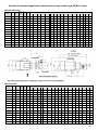
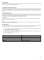
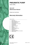
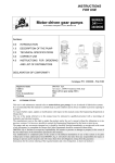
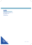
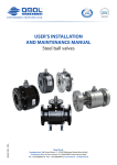
Motor Driven Gear
Pumps
User and
Maintenance Manual
Warranty Information
TABLE OF CONTENTS
1.
2.
3.
4.
5.
6.
7.
8.
9.
10.
11.
12.
13.
14.
15.
16.
17.
http://www.dropsa.com
INTRODUCTION
GENERAL DESCRIPTION
PRODUCT– MACHINE IDENTIFICATION
TECHNICAL SPECIFICATIONS
PUMP COMPONENTS
UNPACKING AND INSTALLING THE PUMP
INSTRUCTIONS FOR USE
TROUBLESHOOTING
MAINTENANCE PROCEDURE
DISPOSAL
ORDERING INFORMATION AND DIMENTIONS
HANDLING AND TRASPORTATION
OPERATING HAZARDS
PRECAUTIONS
WARRANTY INFORMATION
DECLARATION OF COMPLIANCE WITH STANDARDS
DROPSA LOCATIONS
Manual drafted in compliance with
EC Directive 06/42
C2010IE – WK 20/11
1. INTRODUCTION
This user’s and maintenance manual refers to motor-driven gear pumps 37000-3400000, 3410It is recommended that this manual is carefully kept in good condition and is always available to persons requiring to consult it.
To request further copies, updates or clarifications with respect to this manual contact the Engineering Department at Dropsa
SpA.
The use of the pump referred to in this manual must be entrusted to qualified personnel with a knowledge of hydraulics and
electrical systems.
The manufacturer reserves the right to update the product and/or the user’s manual without the obligation to revise previous
versions. It is however, possible to contact the Engineering Department for the latest revision in use. You can find additional
copies and newer revisions of this document from our website http://www.dropsa.com. Alternatively contact one of our sales
offices.
The pump, and any accessories mounted on it, should be carefully checked immediately on receipt and in the event of any
discrepancy or complaint the Dropsa SpA Sales Department should be contacted without delay.
DROPSA S.p.A. declines to accept any responsibility for injuries to persons or damage to property in the event of the nonobservance of the information presented in this manual.
Any modification to component parts of the system or the different destination of use of this system or its parts without prior
written authorisation from DROPSA S.p.A. will absolve the latter from any responsibility for injury or damage to persons and/or
property and will release them from all obligations arising from the guarantee.
Instructions for the correct ordering of the required model, and a list of importers, is shown in Section 4.
2. GENERAL DESCRIPTION
These new pump units have been designed as the result of over thirty years experience in the field of developing and
manufacturing gear pumps.
The application possibilities are numerous; the pumps are self-lubricating and are able to operate with oils or any other fluid
with proven lubricating capacity.
These pumps can therefore be utilised in the fields of lubrication, refrigeration, hydraulics and, more generally, for the
circulation of fluids for machines, motors and linear motion applications; these units can also be employed on recirculating
systems without the need for particularly fine filtering of the circulation fluid.
One of the most striking features of these pumps is the high degree of silentness in operation, obtained with the use of gears
specially designed for this type of unit.
Also, thanks to particularly precise machining and finishing, a significant improvement has been achieved in efficiencies
compared to all previous similar models produced.
To ensure an external seal the pumps have an “O” ring located between the pump body and the relative cover in addition to a
lip seal on the main shaft.
The body of the pump is produced in hydraulic cast iron and the gears and relative shafts in chrome-nickel steel – carburized,
hardened and ground.
The body of the low flow rate pump (up to 500 cc/min) is made of sintered steel; the shafts and gears in carburized and
hardened steel with a seal on the main shaft.
WARNING
For all the motor-driven pumps we have shown the applied power to the motors in function of the maximum pressure demand
indicated in the table. For higher pressures the motor must be suitably sized; accordingly, to obtain a quotation, state the
voltage, the maximum operating pressure and if the service will be continuous or intermittent. (Max pressure = 30 bar for
continuous service); (max. pressure = 60 bar for intermittent service); (For cylinder block versions from 1-30 bar it depends form
delivery and kW). Working temperature of the fluid –20 - +100 degrees with low to medium velocity oil.
On request flameproof motors can be supplied in various voltages.
Request availability from Dropsa SpA.
2
3. PRODUCT – MACHINE IDENTIFICATION
Pump identification label is located on the front side of the grease operating pump and contains pump serial number and details
of its operating parameters.
4. TECHNICAL SPECIFICATION
See chapter 11 “ORDERING INFORMATION”
5. PUMP COMPONENTS
3
6. UNPACKING AND INSTALLING THE PUMP
6.1 UNPACKING
Once a suitable location has been found to install the unit remove the pump from the packaging. Check the pump has not been
damaged during transportation or storage. No particular disposal procedures are necessary, however packing should be
disposed of in accordance with regulations that may be in force in your area or state.
6.2 INSTALLING THE PUMP
Allow sufficient space for the installation, leaving minimum 100 mm (3.9 in.) around the unit.
In order to avoid unnatural posture for personnel install the machine in a comfortable and easy-to-reach location.
Do not install the unit in aggressive/explosive/inflammable environments or on vibrating surfaces.
WARNING: At the end of all the connecting operations, make sure that pipes and wires are safe from impacts and carefully
fixed.
7. INSTRUCTIONS FOR USE
After fixing the pump at its support, fill the tank with pure oil.
Operate the pump until the oil comes out without air bubbles.
Attach the tubing to the pump taking care of blowing compressed air inside to remove any dirt.
Reactivate the pump until oil comes out from the pipes regularly and without bubbles.
Attach piping to the lubrication points
Always pay attention to the direction of rotation.
In case of direct connection, run the engine for a few seconds checking the direction of rotation, if it is wrong to
switch two power phases.
The pump must not work with the wrong direction of rotation.
In the event of a complete unit, pump with electric motor on support, they must be carefully balanced in both
directions, to ensure that whole function silently.
4
8. TROUBLESHOOTING
DIAGNOSTIC TABLE
INDICATION
The pump does not deliver oil or does not
deliver oil in the exact quantity prescribed
PROBABLE CAUSE
Drawing in air due to the tank
being empty
The splash filter is dirty or
blocked
The connections are loose
Pump has deteriorated
Pressure regulating valve loose,
so the oil returns immediately to
the tank before flowing through
the delivery valve
Release valve damaged
The pump does not deliver oil at the prescribed
pressure
Incorrect setting of the
regulating valve
Presence of dirt under the bypass valve
REMEDY
Refill the tank and purge air
from the system
Wash the filter and blow it
through with compressed air
Set all connections ensuring
there are no leakages
Replace the pump
Set the regulating screw until oil
exits from the delivery
Replace the valve
To the pump outlet connect a
tube approximately 30cm long
with a manometer connected to
the free end. Regulate the valve
by means of turning the screw
and reading the corresponding
pressure value on the
manometer
Disassemble the valve and clean
or replace it as necessary
5
9. MAINTENANCE PROCEDURE
The pumps require only minimal maintenance.
To facilitate maintenance it is suggested to install the pump in an easily accessible location
Periodically check piping joints to detect possible leaks.
The machine does not require any special tool for checking or maintenance tasks. However, it is recommended the
use only of appropriate and in good conditions tooling, protective devices (gloves) and clothing (in according to current
regulations) to avoid hazards to equipment or persons.
10. DISPOSAL
During maintenance or disposal of the machine care should be taken to properly dispose of environmentally sensitive items.
Refer to local regulations in force in your area.
When disposing of this unit, it is important to ensure that the identification label and all the other relative documents are also
destroyed.
11. ORDERING INFORMATION
Gear pumps for low flow rates with pressures of 30-70 bar.
Gear pumps for low flow rates can also be supplied assembled to the motors.
3 sizes are available: 0.35 – 0.5 – 1.2 litres/min. at 1500 rpm.
The direction of rotation is indifferent; simply invert the suction and delivery tubes.
The service can be either continuous or intermittent.
The following standard power supplies are provided for:
220/380 V – 50 Hz
240/440 V – 60 Hz
415V
_ 50 Hz
Other voltages and frequencies are available on request.
The motors have IP55 grade protection.
In addition, it is possible to order separately a suction filter c/w dip tube (400 mesh/cm2, filtering grade 260) of an overall length
of between 100 and 455 mm depending on the needs of different installations.
These gear pumps are suitable for operating with oils of a viscosity between 32 and 1000 cSt at fluid working temperatures in
the range of –20 - +100 °C.
The maximum useful pressure in intermittent service is 70 bar; for this the design rotation speed of the pump is 1500 or 3000
rpm.
Assembly Part N°
Pump for
external
3099127
3099004
3099131
Dimension H
Pump in tank
Flow rate in
litres/min
a 1500 rpm
3099129
3099130
3099133
0.35
0.5
1.2
38
40
47
6
LL
Suction filter assembly
Part N° 3088053
Part N°3088054
Part N°3088055
Part N°3088056
LL
Assembly
Part N°
Motor power
Flow rate
litres/min
Weight
Kg
size
kW
rpm
3405000
56
0.09
1500
0.50
3406000
63
0.25
3000
3407000
63
0.185
1500
3402002
56
0.09
1500
Length 165 mm
length 80 mm
length 415 mm
length 130 mm
Dimensions in mm
A
B
C
D
E
F
G
H
L
M
N
P
R
3.7
171
137
104
56
80
65
56
5.5
71
90
6
106
36
1.00
5.5
194
153
119
56
90
75
58
5.5
--
--
--
--
--
0.50
5.5
194
153
119
56
90
75
58
5.5
--
--
--
--
--
0.35
3.7
171
137
104
54
80
65
56
5.5
71
90
6
106
36
7
This assembly consists only of the motor and the gear pump.
Electric motor for
continuous operation
DropsA
Line
01
Intermittent
26
33V
By-pass
setting
2-20 bar
25-80 bar
25-80 bar
Standard
setting
5 bar
By-pass
with
nonreturn
valve
70 bar/
3 PH
50 bar/
3 PH
with
release
valve
Assembly
Motor power
Voltage
Flow
Dimensions
rate
*C
D
litres/mi *A *B
n
0.35
205 156 110 38
Size
kW
rpm
3404023
56
0.09
1500
220/380V-50 Hz
3404022
56
0.09
1500
220/380V-50 Hz
0.50
205
156
110
40
3404026
56
0.06
1500
110 V – 50 Hz
0.35
205
156
110
38
3404046
56
0.06
1500
110 V – 50 Hz
0.50
205
156
110
40
3405099
56
0.09
1500
220/380V – 50 Hz
0.35
205
156
110
38
3405101
56
0.09
1500
220/380V– 50 Hz
0.50
205
156
110
40
3405121
56
0.06
1500
110 V – 50 Hz
0.35
205
156
110
38
3415122
56
0.06
1500
110V – 50 Hz
0.50
205
156
110
40
3405098
56
0.12
1500
220/380V-50 Hz
0.35
187
156
110
38
3405100
56
0.12
1500
220/380V-50 Hz
0.50
187
156
110
40
3405123
56
0.06
1500
110 V – 50 Hz
0.35
205
156
110
38
3405124
56
0.06
1500
110 V – 50 Hz
0.50
205
156
110
40
* NON-STANDARD DIMENSIONS
This assembly is composed of a gear pump, an electric motor, a manometer and a valve block.
Thanks to a by-pass it is possible to regulate the working pressure in accordance with the requirements of the system to which
the pump is connected.
Also included in the valve block is a non-return valve or alternatively a release valve so that it can be adapted for use with the
different DROPSA systems (line 01, line 26, 33V System) or on other systems of a similar nature.
It is also possible to order separately an intake filter with a dip tube (400 mesh/cm2 filtering grade 260) of an overall length
variable between 100 and 455 mm depending on the differing requirements of the installation).
THE MOTOR VOLTAGE MUST ALWAYS BE STATED AT THE TIME OF ORDERING.
8
Gear pumps and electro-gear pumps, (pumps with horizontal fastening)
Max Pressure = 30 bar for continuous working – Max Pressure =60 bar for intermittent working.
Fluid working temperature = 20÷100 ºC with low and medium oil viscosity.
Note: For pumps either with clockwise rotation or bi-rotational with suction on left side, connect suction line to threaded port 1
and delivery line to threaded port 2 ;
For pumps either with counter - clockwise rotation or bi-rotational with suction on right side connect suction line to threaded
port 2 and delivery line to threaded port 1;
WITHOUT BY PASS
Liters
Rotation #
Left
2
3,5
37060
37036
10
19
Right
37021
37024
37040
32
37030
Dimensions (mm)
Weight
kg
Gas
D
E
F
G
H
J
K
L
M
N
O
P
Q
R
S
T
U
V
W
Z
0,9
1/4
40
8,7
10
25
3
11,2
44,5
45,5
25
48
65
8
60
60
14,5
…
…
6
…
1,9
3/8
54
12,3
12
30
4
13,5
57
61
35
60
82
10
80
80
18,5
…
…
9,5
…
3,2
1/2
65
15,2
14
32
5
16
67
73
44
74
96
10
90
98
25
…
…
9,5
…
5
3/4
77,5
18,9
16
34
5
18,8
72
79
50
84
110
10,5
108
116
25
…
…
11,5
…
# Looking at the pump from shaft side
WITH BY PASS
Liters
Rotation #
Left
2
3,5
37061
37111
5,5
10
Right
37022
37063
37039
37025
Dimensions (mm)
Weight
kg
Gas
D
E
F
G
H
J
K
L
M
N
O
P
Q
R
S
T
U
V
W
Z
1
1/4
40
8,7
10
25
3
11,2
44,5
…
25
48
65
8
60
60
14,5
45,5
58
6
…
2,1
3/8
54
12,3
12
30
4
13,5
57
…
35
60
82
10
80
80
18,5
61
78
9,5
…
# Looking at the pump from shaft side
REVERSIBLE
Liters
Sunction
Left
2
37070
3,5
37023
5,5
37071
10
37026
Right
Dimensions (mm)
Weight
kg
Gas
D
E
F
G
H
J
K
L
M
N
O
P
Q
R
S
T
U
V
W
Z
0,9
1/4
40
8,7
10
25
3
11,2
44,5
…
25
48
65
8
60
60
14,5
90
…
6
49,5
1,9
3/8
54
12,3
12
30
4
13,5
57
…
35
60
82
10
80
80
18,5
120,5
…
9,5
69
* Please ask to nearest Dropsa for availability
Dimensions and features may change without notice
9
Gear pump and electro-gear pumps (pumps with flange)
Max Pressure = 30 bar for continuous working – Max Pressure =60 bar for intermittent working.
Fluid working temperature = 20÷100 ºC with low and medium oil viscosity.
Note: For pumps either with clockwise rotation or bi-rotational with suction on left side, connect suction line to threaded port 1
and delivery line to threaded port 2 ;
For pumps either with counter - clockwise rotation or bi-rotational with suction on right side connect suction line to threaded
port 2 and delivery line to threaded port 1;
WITHOUT BY PASS
Liters
2
3,5
5,5
10
19
26
32
*45
Rotation#
Dimensions (mm)
Weight Gas
kg
D
Left
Right
E
F
G
H
J
K
L M N
O
P
Q
R
S
T U V Z
37066 37054
0,9
1/4 70 50 60 5,7 6,5 10 2 3 11,2 32
63
8,7 60 60 15 … … …
37001
37068 37056
1,9
3/8 100 70 84
7
8,5 12 3 4 13,5 42,5
85
12,3 80 80 19 … … …
37018 37004
37007
3,2
1/2 120 90 100
7
9 14 3,5 5 16 53,5 102 15,2 98 90 26 … … …
37058
5
3/4 140 100 120
9
10 16 4 5 18
59
113 18,9 116 108 34 … … …
37123 37010
37013
8
1 150 110 130 11,5 11 18 4 6 20,5 65,5 138,5 22,5 140 130 38 … … …
# Looking at the pump from shaft side
WITH BY PASS
Liters
2
3,5
5,5
10
19
26
32
*45
Rotation#
Dimensions (mm)
Peso Gas
kg
D
Left
Right
E
F
G
H
J
K
L M N
O
P
Q
R
S
T
U
V
37055
1
1/4 70 50 60 5,7 6,5 10 2 3 11,2 32 … 8,7 60 60 15
63
58
37002
37057
2,1 3/8 100 70 84
7
8,5 12 3 4 13,5 42,5 … 12,3 80 80 19
85
78
37016 37005
37082 37008 3,5 1/2 120 90 100
7
9 14 3,5 5 16 53,5 … 15,2 98 90 26 104
86
37059
5,5 3/4 140 100 120
9
10 16 4 5 18
59 … 18,9 116 108 34 117 102,5
37011
37014 8,2
1 150 110 130 11,5 11 18 4 6 20,5 65,5 … 22,5 140 130 38 138,5 113
# Looking at the pump from shaft side
Z
…
…
…
…
…
REVERSIBLE
Liters
2
3,5
5,5
10
19
26
32
Sunction
Dimensions (mm)
Weight Gas
kg
D
Left
Right
E
F
G
H
J
K
L M N
O
P
Q
R
S
37067
0,9
1/4 70 50 60 5,7 6,5 10 2 3 11,2 32 … 8,7 60 60
37020 37003
37069
1,9
3/8 100 70 84
7 8,5 12 3 4 13,5 42,5 … 12,3 80 80
37006
37009
3,2
1/2 120 90 100 7
9 14 3,5 5 16 53,5 … 15,2 98 90
37083
5
3/4 140 100 120 9 10 16 4 5 18
59 … 18,9 116 108
37012
T
U
V
Z
15
63
…
67,5
19
87,5
…
92
26 108,5 … 113,5
34 120,5 …
125
* Please ask to nearest Dropsa for availability
Dimensions and features may change without notice
10
Vertical or horizontal application motor-driven pumps–
motor type B5 4 pole
WITHOUT BY-PASS
Assembl.
Part N.
Liter
s
Power
KW
Press.
max
bar
Weig
ht
3410110
2
0.185
26
3410112
3.5
0.25
3410114
5.5
3410118
10
3410120
Dimensions (mm)
Kg
gas
D
E
G
H
K
I
L
M
N
O
P
Q
R
T
U
V
8.6
1/4
115
148
306
118
---
9
95
11
32
63
8.7
60
---
140
23
20
8.6
1/4
130
167
333
126
---
9
110
129
32
63
8.7
60
---
160
23
0.25
13
10.4
3/8
130
167
355
148
---
9
110
129
42
85
12.3
80
---
160
23
0.25
7
10.4
3/8
130
167
355
148
---
9
110
129
42
85
12.3
80
---
160
23
10
0.55
15
12.9
3/8
165
187
392
159
---
11
130
149
42
85
12.3
80
---
200
28
3410122
19
0.55
8
15.7
1/2
165
187
437
202
---
11
140
149
53
102
15.2
90
---
200
28
3410124
19
0.75
11
17.2
1/2
165
187
437
202
---
11
140
149
53
102
15.2
90
---
200
28
3410126
26
0.75
8
19.5
3/4
165
187
451
214
---
11
150
149
59
113
18.9
108
---
200
28
3410128
26
1.1
12
25
3/4
165
210
473
214
---
11
150
172
159
113
18.9
108
---
200
28
3410130
32
0.75
6
19.5
3/4
165
187
451
214
---
11
150
149
59
113
18.9
108
---
200
28
3410132
32
1.1
10
25
3/4
165
210
473
214
---
11
150
172
59
113
18.9
108
---
200
28
WITH BY-PASS
Assemb.
Part N:
Lite
rs
Pow.
KW
Press..
max
bar
Weig
ht
Kg
gas
D
E
G
H
K
I
L
M
N
O
P
Q
R
T
U
V
3410111
2
0.185
26
8.7
1/4
115
148
---
118
306
9
95
111
32
63
8.7
60
58
140
23
3410113
3.5
0.25
20
8.7
1/4
130
167
---
128
333
9
110
129
32
63
8.7
60
58
160
23
3410119
10
0.25
7
10.6
3/8
130
167
---
148
355
9
110
129
42
85
12.3
80
78
160
23
3410121
10
0.55
15
13.1
3/8
165
187
---
159
392
11
130
149
42
85
12.3
80
78
200
28
3410123
19
0.55
8
16
1/2
165
187
---
204
439
11
140
149
53
104
15.2
90
86
200
28
3410125
19
0.75
11
17.5
1/2
165
187
---
204
439
11
140
149
53
104
15.2
90
86
200
28
3410127
26
0.75
8
20
3/4
165
187
---
218
455
11
150
149
59
117
18.9
108
102.5
200
28
3410129
26
1.1
12
25.5
3/4
165
210
---
218
477
11
150
172
59
117
18.9
108
102.5
200
28
3410131
32
0.75
6
20
3/4
165
187
---
218
455
11
150
149
59
117
18.9
108
102.5
200
28
3410133
32
1.1
10
25.5
3/4
165
210
---
218
477
11
150
172
59
117
18.9
108
102.5
200
28
Dimensions (mm)
11
Vertical or horizontal application motor-driven pumps–motor type B3/B14 4 pole
WITHOUT BY-PASS
Assemb.
Part N.
Lite
rs
Pow.
KW
Press.
max
bar
Weig
ht
3410011
2
0.185
26
3410012
3.5
0.25
3410027
5.5
0.25
3410013
5.5
0.55
3410028
10
3410014
10
3410029
19
3410015
19
3410030
26
3410016
26
3410031
32
3410017
32
3410032
3410018
Dimensions (mm)
Kg
gas
D
E
F
G
H
K
I
Y
L
M
N
O
P
Q
R
S
T
U
V
8.6
1/4
80
127
155
306
118
-
63
7
8
111
32
63
8.7
60
100
-
120
100
20
8.6
1/4
90
140
173
333
126
-
71
7
9
129
32
63
8.7
60
112
-
136
110
13
10.4
3/8
90
150
173
355
148
-
71
7
9
129
42
85
12.3
80
112
-
136
110
29
12.9
3/8
100
166
192
392
159
-
80
9
10
149
42
85
12.3
80
125
-
155
125
0.25
7
10.4
3/8
90
150
173
355
148
-
71
7
9
129
42
85
12.3
80
112
-
136
110
0.55
15
12.9
3/8
100
166
192
392
159
-
80
9
10
149
42
85
12.3
80
125
-
155
125
0.55
8
15.7
1/2
100
203
192
437
204
-
80
9
10
149
53
102
15.2
98
125
-
155
125
0.75
11
17.2
1/2
100
203
192
437
204
-
80
9
10
149
53
102
15.2
98
125
-
155
125
0.75
8
19.5
3/4
100
210
192
451
218
-
80
9
10
149
59
113
18.9
116
125
-
155
125
1.1
12
25
3/4
100
216
216
473
218
-
90
9
11
172
59
113
18.9
116
140
-
174
128
0.75
6
19.5
3/4
100
210
192
451
218
-
80
9
10
149
59
113
18.9
116
125
-
155
125
1.1
10
25
3/4
100
216
216
473
218
-
90
9
11
172
59
113
18.9
140
140
-
174
128
45
1.1
7
28.5
1
100
222.5
216
494.5
239.5
-
90
9
11
172
65.5
138.5
22.5
140
140
-
174
128
45
2.2
15
48.5
1
140
238.5
238
570
248.5
- 100
12
12
196
65.5
138.5
22.5
140
160
-
196
170
Weig
ht
gas
WITH BY-PASS
Assemb.
Part N.
Liter
s
Pow.
KW
3410019
2
0.185
3410020
3.5
0.25
3410033
5.5
3410021
3410034
Pres.
max
bar
Dimensions (mm)
Kg
D
E
F
G
H
K
I
Y
L
M
N
O
P
Q
R
S
T
U
V
26
8.7
1/4
80
127
155
-
118
306
63
7
8
111
32
63
8.7
60
100
58
120
100
20
8.7
1/4
90
140
173
-
126
333
71
7
9
129
32
63
8.7
60
112
58
136
110
0.25
13
10.6
3/8
90
150
173
-
148
355
71
7
9
129
42
85
12.3
80
112
78
136
110
5.5
0.55
29
13.1
3/8
100
166
192
-
159
392
80
9
10
149
42
85
12.3
80
125
78
155
125
10
0.25
7
10.6
3/8
90
150
173
-
148
355
71
7
9
129
42
85
12.3
80
112
78
136
110
3410022
10
0.55
15
13.1
3/8
100
166
192
-
159
392
80
9
10
149
42
85
12.3
80
125
78
155
125
3410035
19
0.55
8
16
1/2
100
203
192
-
206
439
80
9
10
149
53
104
15.2
98
125
86
155
125
3410023
19
0.75
11
17.5
1/2
100
203
192
-
206
439
80
9
10
149
53
104
15.2
98
125
86
155
125
3410036
26
0.75
8
20
3/4
100
210
192
-
222
455
80
9
10
149
59
117
18.9
116
125
102.5
155
125
3410024
26
1.1
12
25.5
3/4
100
216
216
-
222
477
90
9
11
172
59
117
18.9
116
140
102.5
174
128
3410037
32
0.75
6
20
3/4
100
210
192
-
222
455
80
9
10
149
59
117
18.9
116
125
102.5
155
125
3410025
32
1.1
10
25.5
3/4
100
216
216
-
222
477
90
9
11
172
59
117
18.9
116
140
102.5
174
128
3410038
45
1.1
7
29
1
100
222.5
216
-
239.5
494.5
90
9
11
172
65.5
138.5
22.5
140
140
113
174
128
3410026
45
2.2
15
49
1
140
238.5
238
-
248.5
570
100
12
12
196
65.5
138.5
22.5
140
160
113
196
170
3410067
60
2.2
11
52
1
140
238.5
238
-
248.5
570
100
12
12
196
65.5
138.5
22.5
140
160
113
196
170
12
12. DIMENSIONS
See tables in charter 11 “ORDERING INFORMATION”
13. HANDLING AND TRANSPORTATION
Prior to shipping, the equipment is carefully packed in a cardboard package. During transportation and storage, pay attention to
the side on the cardboard packing. On receipt, check that the packing is not damaged. Then, storage the machine in a dry
location.
14. OPERATING HAZARDS
It is necessary to carefully read about the instructions and the risks involved in the use of lubrication machines. The operator
must know the machine functioning through the User and Maintenance Manual
Inflammability
The lubricant generally used in lubrication systems is not normally inflammable. However, it is advised to avoid contact with
extremely hot substances or naked flames.
Pressure
Prior to any intervention, check the absence of residual pressure in any branch of the lubricant circuit as it may cause oil
sprays when disassembling components or fittings.
15. PRECAUTIONS
No particular operating hazards characterize Motor Driven Gear pumps, except for the following precautions:
Contact with fluid to break/open feed pipe. The operator must use appropriate protective clothing, gloves and take all
necessary safety precautions (D. Lgs. 81/08).
Awkward postures . Follow instruction in section 6.2.
Contact with oil during refilling / maintenance. The operator must use appropriate protective clothing, gloves and take
all necessary safety precautions (D. Lgs. 81/08).
Using the wrong lubricants:
Fluids
Lubricants containing abrasive components
Lubricants containing silicon
Petrol – solvents – inflammable liquids
Corrosive products
Water
Food Products
Dangers
Premature wear of pump
Pump failure
Fire – explosion –seal damage
Pump damage - danger to persons
Pump oxidization
Contamination of the product
13
16. WARRANTY INFORMATION
All products manufactured and marketed by Dropsa are warranted to be free of defects in material or workmanship for a period
of at least 12 months from date of delivery. Extended warranty coverage applies as follows:
Complete system installation by Dropsa: 24 Months
All other components: 12 months from date of installation; if installed 6 months or more after ship date, warranty shall be
maximum of 18 months from ship date.
If a fault develops, notify us giving a complete description of the alleged malfunction. Include the part number(s), test record
number where available (format xxxxxx-xxxxxx), date of delivery and installation and operating conditions of subject product(s).
We will subsequently review this information and, at our option, supply you with either servicing data or shipping instruction
and returned materials authorization (RMA) which will have instructions on how to prepare the product for return. Upon
prepaid receipt of subject product to an authorized Dropsa Sales & Service location, we will then either repair or replace such
product(s), at out option, and if determined to be a warranted defect, we will perform such necessary product repairs or replace
such product(s) at our expense.
Dropsa reserves to right to charge an administration fee if the product(s) returned are found to be not defective.
This limited warranty does not cover any products, damages or injuries resulting from misuse, neglect, normal expected wear,
chemically caused corrosion, improper installation or operation contrary to factory recommendation. Nor does it cover
equipment that has been modified, tampered with or altered without authorization.
Consumables and perishable products are excluded from this or any other warranty.
No other extended liabilities are states or implied and this warranty in no event covers incidental or consequential damages,
injuries or costs resulting from any such defective product(s).
The use of Dropsa product(s) implies the acceptance of our warranty conditions. Modifications to our standard warranty must be
in made in writing and approved by Dropsa.
14
17. DECLARATION OF COMPLIANCE WITH CE STANDARDS
Dropsa Spa
Via Benedetto Croce, 1
20090 Vimodrone (MI)
Italy
Tel.:
Fax Sales:
E-mail:
Web site:
(+39) 02. 250.79.1
(+39) 02. 250.79.767
[email protected]
http://www.dropsa.com
DICHIARAZIONE
DI CONFORMITÁ/DECLARATION OF COMPLIANCE WITH STANDARDS/
DECLARATION DE CONFORMITE/ KONFORMITÄTSERKLÄRUNG DES STANDARDS /DECLARACIÓN DE
CONFORMIDAD/ DECLARAÇÃO DE CONFORMIDADE
La società Dropsa S.p.A., con sede legale in Milano, Via Besana,5/ Dropsa S.p.A., registered office in Milan, Via
Besana,5 / Dropsa S.p.A. au Siège Social à Milan, Via Besana,5/ Dropsa S.p.A., Sitz in Milano, Via Besana 5/ La
sociedad Dropsa S.p.a., con sede legal en Milán, Via Besana,5/ A Dropsa S.p.A, com sede em Milão, via Besana, nº 5
DICHIARA /CERTIFIES / CERTIFIE/ ZERTIFIZIERT, DASS/ DECLARA/ CERTIFICA:
che la macchina denominata/that the machine named / que la machine dénommée/ Die Maschine mit der
Bezeichnung/ que la máquina denominada/ que o equipamento denominado
ELETTROPOMPE AD INGRANAGGI TIPO 37000, 3400000, 3410...
è conforme alle condizioni previste dalle Direttive CEE /has been constructed in conformity with the Directives Of
The Council Of The European Community on the standardization of the legislations of member states/ a été
construite en conformité avec les Directives Du Conseil Des Communautes Europeennes/ Entsprechend den
Richtlinien des Rates Der Europäischen Union, für die Standarisierung der Legislative der Mitgliederstaaten,
konstruiert wurde/ cumple con las condiciones establecidas por las directivas comunitarias/ foi construído em
conformidade com as diretivas do Conselho das Comunidades Europeias:
2006/42 Direttiva macchine /Machinery Directive / 2006/42 Directive machines / Maschinenrichtlinien/
Maquinaria 2006/42/CEE /Directiva 2006/42 Máquinas;
2006/95 Bassa tensione/ Electrical Safety: Low Voltage Directive/2006/95 Sécurité électrique: Directive
Basse Tension/Elektrische Sicherheit: Niedrigspannungsrichtlinien/Seguridad eléctrica 2006/95:
Directiva de baja tensión/Segurança Elétrica 2006/95: Directiva de Baixa Tensão
Vimodrone (MI), April 2011
Technical Director:
Maurizio Greco
…………………………
Legal representative
Milena Gavazzi
…………………………
15
18. DISTRIBUTORS
Dropsa S.p.A.
Via B. Croce,1
20090 Vimodrone (MI) Italy.
Tel: (+39) 02 - 250.79.1
Fax: (+39) 02 - 250.79.767
E-mail: [email protected] (Export)
E-mail: [email protected] (National)
Dropsa Ame
23, Av.des.Morillons
Z.I. des Doucettes 91140
Garges Les Gonesse, France
Tel: (+33) 01 39 93 00 33
Fax: (+33) 01 39 86 26 36
E-mail: [email protected]
Dropsa (UK) Ltd
Unit 6, Egham Business Village,
Egham,Surrey,TW20 8RB
Tel: (+44) 01784 - 431177
Fax: (+44) 01784 - 438598
E-mail: [email protected]
Dropsa do Brazil Ind. E Com. Ltda
Rua Sobralia 175,
Sao Paulo, Brazil
Tel: (+55) 011-5631-0007
Fax: (+55) 011-5631-9408
E-mail: [email protected]
Dropsa USA Inc.
6645 Burroughs Ave
48314-2132 Srerling Hts,Mi Us -USA
Tel: (+1) 586-566-1540
Fax: (+1) 586-566-1541
E-mail: [email protected]
Dropsa Lubrication Systems
Nr 8 Dongxing Road,
Songjiang Industrial Zone
(Shanghai) Co., Ltd
Tel: +86 (021) 67740275
Fax: +86 (021) 67740205
E-mail: [email protected]
Dropsa Gmbh
Volmerswerther Strasse 80
40221 Dusseldorf 1, Deutschland
Tel: (+49) 0211/39 4011
Fax:(+49) 0211/39 4013
E-mail: [email protected]
Dropsa Australia Pty.
C20/148 Old Pittwater Road
Brookvale, NSW 2100
Tel: +61 (02) 9938 6644
Fax: +61 (02) 99 386 611
E-mail: [email protected]
Web site: http://www.dropsa.com - E-mail: [email protected]
16