1
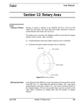
Fadal
User Manual
Section 9: Cutter Radius Compensation
Cutter Radius
Compensation
Cutter Radius Compensation (CRC) is used in a program to allow the operator
to alter the path of a cutter.
UNDERSIZED PART OUTLINE
GOOD PART OUTLINE
PFAD 1
PFAD 2
Figure 9-1 Cutter Radius Compensation
EXAMPLE:
After cutting the part with path 1, the operator measured the part and
determined that the part was undersized. By increasing the amount of the
diameter in the tool table and running the program again with another part in
the fixture, path 2 cut the part to the correct dimension.
Format 1
The H word in the program will pick up the tool length offset (TLO) and the tool
diameter offset. It should be used before using the G41 or G42 codes. The D
word can be used to pick up a new diameter, however, it is not necessary in
Format 1. If a D word is used, it should appear in the program after the H word.
Whatever diameter is picked up by the H word is then overwritten by the D
word. It can be used on the same line as the G41 or G42 codes.
Format 2
April 2003
M6 T1
G0 G90 S7500 M3 X-2. Y-1.
H1 M7 Z.1 The H will pick up the TLO and the diameter from the tool table
The H word in the program will only pick up the tool length offset (TLO). It
should be used before using the G41 or G42 codes.
Section 9: Cutter Radius Compensation
203
Fadal
User Manual
The D word must be used to pick up the tool diameter. It can be used on the
same line as the G41 or G42 codes or on any line before the G41 or G42 codes.
M6 T3
G0 G90 S800 M3 X3.641 Y-2.224
H3 D3 M8 Z.1 The H and the D words are used to pick up the TLO and the tool
diameter
G40 - Cancel Cutter
Radius
Compensation
See G42.
G41 - Climb Cut
(cutter left)
See G42.
G42 - Conventional
Cut (cutter right)
The G40, G41, or the G42 can be used before or after other codes in a line,
without changing what happens. G41 X1. G1 F35. and G1 X1. F35. G41 would
both function the same way.
G41: OFFSET THE CUTTER TO THE LEFT
OF THE PROGRAMMED PATH
G42: OFFSET THE CUTTER TO THE RIGHT
OF THE PROGRAMMED PATH
Figure 9-2 Conventional Cut
204
Section 9: Cutter Radius Compensation
April 2003
Fadal
Climb and
Conventional Cutting
User Manual
G41
G41
G41: CLIMB CUT THE PROGRAMMED
PATH
Figure 9-3 Climb Cutting
Climb cut the inside of a part by following a general counterclockwise path.
Climb cut the outside of a part by following a general clockwise path.
G42
G42
G42: CONVENTIONAL CUT THE
PROGRAMMED PATH
Figure 9-4 Conventional Cutting
Conventional cut the inside of a part by following a general clockwise path.
Conventional cut the outside of a part by following a general counter clockwise
path.
April 2003
Section 9: Cutter Radius Compensation
205
Fadal
User Manual
The H and the D
Word with CRC
H and D Word Use
Cutter Radius Compensation must be called with offset call. In Format 1 mode,
the offset number is selected by the use of an H word. In Format 2, the D word
is used. The amount applied will be 1/2 the diameter specified in the table.
Positive or negative diameters are allowed. A negative diameter will cause the
displacement in the opposite direction. In Format 2 mode, the cutter offset
specification in the tool data table may be changed to register diameter or
radius
(see Section 8, SETP). The D word in the program (Format 2) indicated which
offset to use. In Format 1, the use of the D word will override any diameter
offset selected by the last H word. The next H word will override the previous D
word.
The use of the H99 with the Q word, in Format 1, may be used to specify a
specific tool diameter. This diameter value given to the Q word is placed into
the tool table location 99. This new value will be used until a new H word or D
word is specified.
EXAMPLE:
Advantages of Climb
Cutting
206
M6 T1 (.506 E.M.
G0G90S200 M3 E1 X0Y0
H1 Z.1
G1 Z-1.
G41X3.
Y2.
H99 Q.5 This specified a tool diameter of .5
To reverse direction of cut the G41 or G42 mode can be switched without
canceling the other code. This can be used when kellering (cutting in both
direction to remove material).
When using climb cuts, the cutter will bend away from the wall being cut. This
will automatically leave stock on the wall. Because it will leave stock, this will
eliminate the need to program a different roughing pass around the part
outline. A roughing pass and a finish pass will result from using the same path
two times around the outline. After material has been removed on the first
pass, tool pressure is reduced and the tool will not bend on the second pass.
Sometimes more than two passes are required depending on the length and
type of cutter and on the type of material being cut. For a second pass use the
copy command to copy the program, or use subroutines or subprograms.
Section 9: Cutter Radius Compensation
April 2003
Fadal
User Manual
Simply increasing the diameter of the tool in the tool table will not always work
for a roughing pass. Inside radii could be a limiting factor. If the tool diameter is
increased to a size larger than an inside radius on the part outline, a “TOOL
DIAMETER TOO LARGE” message will appear.
.005/.015
FINISHED FLOOR
Figure 9-5
Note: The tool is bending the first time around, so program the tool to be .005
to .015 above any floors (the longer the tool the more it will bend). On the
second or final pass, program the tool to cut the floor. The second pass
may also use a different feedrate and spindle RPM.
Note: Because of the rigidity of a bed style vertical machining center, it is not
necessary to program a conventional cut around the part outline and then
finish the part with a climb cut. Although this is true for most materials,
plastics and hardened materials are the exception.
In most cases climb cutting will allow the tool to last longer. It is not
recommended to use climb cutting through a hardened surface, as in a
welded, flame hardened, flame cut, hard anodized, or a hot rolled surface.
Climb cutting allows a higher RPM to be used, and along with a higher RPM,
higher feed rates (as compared to conventional cutting).
The heat created at the tool and work piece is less with a climb cut than with a
conventional cut. With tools as short as possible and a high RPM, the chips will
take the heat away from the tool and the work piece.
Note: When using a higher RPM, use cutters with good chip clearance. Use
two or three fluted end mills in place of cutters with four or more flutes.
Advantages of
Conventional Cutting
April 2003
Use conventional cutting to “scoop out” or cut through hardened material. If
the cutter is deep enough to start the chip in soft material, the chip will
Section 9: Cutter Radius Compensation
207
Fadal
User Manual
continue to form up through the hard material. This will break down the cutter,
but it will last longer than using a climb cut.
The heat between the cutter and the work piece is greater with a conventional
cut, so a this cut is used for a finish cut for some plastics. It will leave a
smoother finish than a climb cut.
In some cases a conventional cut is used to push a flimsy part up against a
fixture. If a climb cut was used, the part would not have any support and would
bend because of the cutting action.
!
Guidelines for Using
CRC
WARNING: Climb cutting causes the cutter to bend away from the wall
being cut, and conventional cutting will cause the cutter to bend into the
wall being cut.
Use CRC (G41, G42) only when cutting a part outline (part path program).
Program motion of the center of the tool when cutting areas other than walls,
using G40 (CRC cancel). When programming the motion of the center of the
cutter (tool path program) using G40, the control will not alter the path.
PART PATH PROGRAM
(CRC IS USED)
G40
G41
TOOL PATH PROGRAM
(CRC NOT USED)
Figure 9-6 Using CRC
CRC (G41, G42) should only be used when cutting a part outline. Program the
outline of the part (using the print dimensions). The control will compensate for
208
Section 9: Cutter Radius Compensation
April 2003
Fadal
User Manual
the radius of the cutter being used and cut to leave the programmed part
outline.
TO CLEAN OUT THE POCKET
PROGRAM THE MOVEMENT OF THE CENTER
(TOOL PATH PROGRAM)
NUR CRC BENUTZEN UM DIE WÄNDE
(PART PATH PROGRAM)
Figure9-7
Note: Cutter Radius Compensation must be canceled prior to locating the
center line of the tool to a specific point.
General Rules
+
1
G41
2
4 +
G40
3
Figure 9-8 General Rules
1) G90 X-.4 Y.4
to be cut
Position the tool, at least the tool radius away from the wall
2) Y0 G41 G1 F10. With the move to the wall, use G41 to apply CRC
3) X3.01 Move along the wall
4) Y.4 G0 G40 With the move away from the wall being cut, use a G40 to
cancel comp
April 2003
Section 9: Cutter Radius Compensation
209
Fadal
User Manual
Note: The distance of the move up to the wall and away from the wall must be
greater than or equal to the radius of the cutter.
Examples of
Applying and
Canceling CRC
These examples represent part outlines and are intended to give general ideas
on applying and canceling cutter radius compensation.
G40
1
2
.
G41
Figure 9-9 Applying & Canceling CRC (1)
1) Position the tool, at least the tool radius away from the boss.
2) Apply CRC along with the move up to the boss.
3) Program the circular move.
4) Cancel CRC along with the move back to the first position.
G40
6
5
3 4
1
.
2
G41
Figure 9-10 Applying & Canceling CRC (2)
1) Position the tool, at least the tool radius away from the line from 2 to 3.
2) Apply CRC along with the move from position 1 to 2.
3) Complete the entire path.
210
Section 9: Cutter Radius Compensation
April 2003
Fadal
User Manual
4) Cancel CRC along with the move from position 5 to 6.
2
4
. 1
3
6
5
Figure 9-11 Applying & Canceling CRC (3)
1) The radius of the lead in lead out radius must be larger than the radius of
the tool to be used.
2) Apply CRC along with the move from position 1 to 2.
3) Complete moving around the path.
4) Cancel CRC along with the move from position 5 to 6.
4
1
G40
3
2
G41
Figure 9-12 Applying & Canceling CRC (3)
1) Apply CRC with the move from position 1 to 2. Position 1 must be at least
the radius of the tool to be used away from the edge of the circle to be cut.
Position 1 does not need be at the center of the circle.
2) Cut counter clockwise around the circle.
3) Cancel CRC along with the move away from the circle from position 3 to 4.
April 2003
Section 9: Cutter Radius Compensation
211
Fadal
User Manual
5
6
3
1
4
2
Figure 9-13 Applying & Canceling CRC (4)
1) The radius of the lead in lead out radius must be larger than the radius of
the tool to be used.
2) Apply CRC along with the move from position 1 to 2.
3) Complete moving around the path.
4) Cancel CRC along with the move from position 5 to 6.
12
1
G40
G41
11
2
3
4
10
5
6
9
7
8
Figure 9-14 Applying & Canceling CRC (5)
212
Section 9: Cutter Radius Compensation
April 2003
Fadal
User Manual
1) Apply CRC along with the move up to the part wall (from position 1 to 2).
2) Move around the part.
3) Cancel CRC along with the move away from the part (from position 11 to
12).
G41
G40
Figure 9-15 Applying & Canceling CRC (6)
1) Apply CRC along with the move up to the part wall. This move must be at
least the radius of the tool to be used away from the part.
2) Move in a general clockwise direction around the outside of the part (for
climb cut).
3) Cancel CRC along with the move away from the part. Again, this move must
be at least the radius of the tool to be used away from the part.
G40
G41
Figure 9-16 Applying & Canceling CRC (7)
1) Apply CRC along with a move up to an extended wall from the part. This
move must be at least the radius of the tool to be used away from the part.
April 2003
Section 9: Cutter Radius Compensation
213
Fadal
User Manual
2) Move in a general clockwise direction around the outside of the part (for
climb cut) to an extended line off the wall of the part.
3) Cancel CRC along with the move away from the extended line. Again, this
move must be at least the radius of the tool to be used away from the
extended line.
O-Ring Groove
Example
In an O-ring groove, consider both circles of the groove as separate walls.
1) Start at the midpoint between the walls.
2) Apply CRC (comp) moving to the first circle.
3) Cut the circle.
4) Cancel comp moving back to the midpoint.
Figure 9-17 O-Ring Groove
Following the general rule, always cancel CRC when leaving a wall. When going
from one wall to the other, cancel comp moving to the midpoint, then apply
comp again moving to the other wall.
5) Apply comp moving to the second circle.
6) Cut the circle.
214
Section 9: Cutter Radius Compensation
April 2003
Fadal
User Manual
7) Cancel comp moving back to the midpoint.
Perpendicular Rule
Figure 9-18 Perpendicular Rule
It is best to apply and cancel comp using moves perpendicular to the wall.
When perpendicular moves are used, the cutter will follow the programmed
move. Otherwise, the cutter will not follow the move to or away from the wall.
Moving perpendicular to and from a wall is best. When comp is on, the tool will
remain perpendicular (tangent) to the wall it is touching. Beginning and ending
the move perpendicular will keep the tool perpendicular for the entire
programmed path.
Comp can be applied with a move that is not perpendicular; however, the
actual move the tool will make when it is moving up to and away from the wall
cannot be predicted. Even though it is possible to turn comp on, with a move
that is not perpendicular the wall, this method is not recommended.
Any line, at any angle, that extends through the center of a circle is considered
perpendicular to the circle. When starting comp such a line is recommended
for contoured walls.
April 2003
Section 9: Cutter Radius Compensation
215
Fadal
User Manual
Fillet Radii and Step
Downs
Figure 9-19 Fillet Radii and Step Downs
All features on a print have tolerances. Inside corner radii (“fillet” or “blend”
radii) usually have more tolerance than other features. Take advantage of this
and program inside corner radii larger than the radius of the tool to be used for
cutting the part. Also remember, when a larger tool diameter is going to be
used for a roughing pass, program fillet radii larger than the intended tool
radius. In the drawing above, the tool radius in the tool table is too large for the
programmed fillet radius. In the drawing below, the programmed fillet radius is
larger than the tool radius in the tool table. The operator can increase the tool
radius in the table up to the smallest inside fillet radius.
Figure 9-20 Fillet Radius Larger than Tool Radius
In the drawing above, the step down distance is smaller than the radius of the
tool. The cutter will not be able to step down, and a TOOL DIAMETER TOO
LARGE message will appear. The picture below shows how to program a fillet
radius from the corner of the step and tangent to the bottom wall. Again make
the fillet radius large enough to accept a radius for a roughing pass.
Note: It is always better to program a fillet radius between two intersecting
features, rather than to leave them as steps and intersections.
216
Section 9: Cutter Radius Compensation
April 2003
Fadal
User Manual
Program Example
The print above shows the inside radii as .375 in four places. A .75 end mill
could be used to form the inside radii; however, if the end mill is used to form
the inside radii, the cutter will bend into the corners and chatter. By
programming an inside corner radius larger than the radius of the tool to be
used, the problem of bending into the corner and chattering will be eliminated.
Drilling out the corners, slowing down, speeding up or dwelling in the corners
will not work!
Sometimes the tolerances do not allow the programmer to program an inside
corner radius larger than a common sized end mill. For example, a print may
allow the corner to be no larger than .250. Using a .5 end mill would cause the
cutter to form the inside radius. When forming an inside radius with the radius
of the cutter is not desirable, use a .375 cutter or reground .5 end mill and
contour the .250 fillet radius.
Note: Never use a cutter to form an inside corner radius and expect good
results on the part!
Note: Always contour an inside corner radius!
EXAMPLE:
April 2003
N1 O1 (CRC RECTANGULAR WINDOW EXAMPLE
N2 L100 (POCKET
N3 Y-1.12
N4 X.875 Y-1.5 I.375 J0 G3
N5 X1.625
N6 X2. Y-1.125 I0 J.375
N7 Y-.875
N8 X1.625 Y-.5 I-.375 J0
N9 X.875
Section 9: Cutter Radius Compensation
217
Fadal
User Manual
N10 X.5 Y-.875 I0 J-.375
N11 M17
N12 M30
N13 (TOOL #1, 3/4 2FL EM (CRC)
N14 G0 G90 S5000 M3 E1 X.875 Y-.875
N15 H1 D1 M7 Z.1
N16 G1 Z-.4 F10. G8
N17 X.5 G41
N18 F35.
N19 L101
N20 F45.
N21 L101
N22 X.875 G40
N23 M5 M9
N24 G0 H0 G90 Z0
N25 M6 T2
The subroutine includes only the moves around the wall of the window.
Programming in this manner allows the subroutine to be called up two times for
two passes around the wall. The move up to the wall at N17 turns comp on,
and is using the feedrate from N16. A new feed at N18 is programmed and
then the sub is called one time at N19. A feedrate change is made at N20, then
the sub is called again at line N21. When running this program, the moves will
look as if they are continuous from the first time around to the second time
around. This is because all of these moves are preprocessed. The move away
from the wall, while turning comp off, is made at line N22.
Corner Rounding
When cutter radius compensation is applied, it can use two different methods
to move around a corner: rolling and intersectional.
Figure 9-21 Corner Rounding
218
Section 9: Cutter Radius Compensation
April 2003
Fadal
User Manual
M96 Cancel
Intersectional CRC
(Rolling)
Figure 9-22 Rolling
M97 Intersectional
CRC
The M96 or M97, as default codes, can be selected when using the SETP
command.
The M96 mode of CRC is more commonly used. In most cases it is also the
safer mode. Using this mode insures that the tool will always be touching the
programmed walls. An M97 allows the tool to move away from the
programmed walls, where it might gouge some other programmed feature.
These two codes are named by the way they move around any corner:
tangentially for M96 and intersectionally for M97.
When to use M96
and M97
Each code produces a different type of corner on the floor; however, both will
cut a mitered corner on all top edges.
Figure 9-23 Using M96 and M97
April 2003
Section 9: Cutter Radius Compensation
219
Fadal
User Manual
Figure 9-24 Rounded/Mitered Corners
M96 produces a rounded corner on the floor. M97 produces a mitered corner
on the floor.
Note: Some prints will specify the type of corner needed on the part. In most
cases the type of rounding used will only affect the part visually, not
functionally.
M96 and M97 are default codes, and can be established by using the SETP
command. M96 is more commonly used as default because M97 causes the
tool to bypass a corner which may cause the tool to bump into another portion
of the part.
If a part has steps, and blend radii were not used to move up and down the
steps, use M97. The control will accept the program better than in the M96
mode. As mentioned earlier in regards to fillet radii and step downs, it is better
to always program a fillet radius between two intersecting features, rather than
to leave these features as steps and intersections. If fillet radii are
programmed, use the M96 mode.
Grooves, slots, and O-ring grooves should use M96. This is most important
when the diameter of the tool is almost equal to the width of the slot or groove.
CRC & Z Axis Moves
220
While CRC is in effect, a Z move can be made to move to a new Z level or to
execute a helical move. The control will “look ahead” of Z moves and
compensate the cutter for the next X or Y move.
Section 9: Cutter Radius Compensation
April 2003
Fadal
User Manual
M6 T1 (TOOL #1, 1/2 DIA. FINISH EM (CRC)
G0 G90 S6000 M3 E1 X24.5 Y.3
H1 M7 Z-.5
X24.2 G41
Y-1.02 G1 F35.
Z-.2 Here is a move to a new Z level with CRC still in effect
Y-1.9 G5
Y-2.02
X24.5 G0 G40
Applying
Compensation with
a Z Move
CRC can be applied along with a Z move. When comp is applied with a Z move,
the cutter will offset tangent to the next X or Y axis move. The next line for the
control to move tangent to can be a linear move or a circular move.
Note: Format 1 and Format 2 apply the offset differently.
EXAMPLE:
Format 1
A G41/G42 in the same line with a Z move will offset the cutter before making a
Z minus move and after a Z plus move.
M6 T1 (TOOL #1, 3/4 DIA. EM (CRC)
G0 G90 S1500 M3 E1 X.6 Y-4.6
H1 Z.1 M7
Z-.52 G41 Here the cutter offsets first, then the Z move is made
X0 Y-3.7 G1 F15.
Y.02
Z.1 G0 G40 Here the Z move is made first, then comp is canceled
Note: The example program above will operate differently in Format 2. See the
next example program for Format 2.
EXAMPLE:
Format 2
In Format 2 the Z move and the offset move will be made together.
M6 T1 (TOOL #1, 3/4 DIA. EM (CRC)
G0 G90 S1500 M3 E1 X.6 Y-4.6
H1 Z.1 M7
Z-.52 G41 Here the offset and Z axis move at the same time
X0 Y-3.7 G1 F15.
Y.02
April 2003
Section 9: Cutter Radius Compensation
221
Fadal
User Manual
Z.1 G0 G40 Here the Z axis moves and the offset is canceled at the same time
EXAMPLE:
Format 1 & 2
The sample program below will operate in the same way for Format 1 and
Format 2.
M6 T1 (TOOL #1, 3/4 DIA. EM (CRC)
G0 G90 S1500 M3 E1 X.6 Y-4.6
H1 Z.1 M7
G41 Here the cutter offsets
Z-.52 Then the Z move is made
X0 Y-3.7 G1 F15.
Y.02
Z.1 G0 Here the Z move is made
G40 Then comp is canceled
222
Section 9: Cutter Radius Compensation
April 2003
Fadal
User Manual
Applying
Compensation with
a Z Move on a Circle
Figure 9-25 Cutter Offset
EXAMPLE:
Format 1 & 2
The sample program below will operate in the same way for Format 1 and
Format 2.
M6 T1 (TOOL #1, 3/4 DIA. EM (CRC)
G0 G90 S1500 M3 E1 X2.4 Y-1.2
H1 Z.1 M7
G41 Here the cutter offsets perpendicular to the circle
Z-.52 Then the Z move is made
X-1. Y-1.1225 I-1.4 J-4.8 G3 Here the circle cut is made
Z.1 G0 Here the Z move is made
G40 Then comp is canceled
April 2003
Section 9: Cutter Radius Compensation
223
Fadal
User Manual
Compensation
Example
Figure 9-26 Compensation Example
EXAMPLE:
Format 1 & 2
The sample program below will operate in the same way for Format 1 and
Format 2.
M6 T1 (TOOL #1, 1/2 DIA. EM (CRC)
G0 G90 S5000 M3 E1 X.332 Y-2.2 This moves to point one
H1 Z.1 M7
G41 Comp is applied perpendicular to the next move
Z-.27 Z moves down
X0 Y-1.625 G1 F30.
Y-.25
X.25 Y0 I.25 G3
Y.3 G40 G0 Comp is canceled along with the move away from the wall being
cut
Z.1
X1.75 This moves to point six
Z-.27
Y0 G41 Comp is applied with the move up to the wall to be cut
X2. Y-.25 J-.25 G3
Y-1.625
X1.668 Y-2.2
Z.1 G0 Z moves up perpendicular to position ten
G40 Comp is canceled and positions over point ten
224
Section 9: Cutter Radius Compensation
April 2003