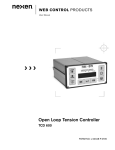
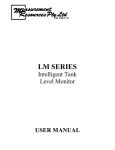
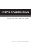
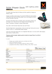
1
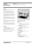
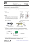
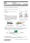
General
Specifications
US300FM
Ultrasonic Flowmeter
GENERAL
US300FM is a ultrasonic flowmeter that measures the flow in a
pipe fully filled with liquid.
It can be fixed to the wall or to the 2” (50mm) pipe with optional
pipe mounting fixture. The housing and the transducers are made
for rough industrial environment.
The measuring principle is based on the influence of the flowing
fluid to the travelling time of sound. The sound is transmitted
through the pipe and the transit time difference between the
forward and backward beams is used to determine the flow
velocity (transit time method).
The measurement is non-intrusive. No cutting of the pipe is
necessary. The measurement is independent of fluid pressure or
conductivity. Owing to its clamp on transducers the installation is
easy.
For the hygienic measurement, there is no risk of contamination
and suitable for ultra clean liquids as the transducers do not
touch the liquid. Also, there is no risk of corrosion when used
with aggressive media.
The instrument can work with up to two pairs of transducers.
This enables you to measure the average flow for disturbed flow
profile (two path measurement), the differential flow of two
independent flows, or simply two different flows independently.
FEATURES
• Maximum two channel inputs (two path measurement) possible
• Two current outputs maximum (The flow data and the sound
speed in the liquid can be assigned at the same time)
Small and light (depth about 7cm, weight about 2.8kg)
Wall mounting or optional 2” (50mm) pipe mounting
Intdractive set-up menu for easy installation
Three types of transducers cover the pipe size from 25mm to
6500mm. For the fluid temperature, one for general
temperature (up to 130 deg C) and the other for high
temperature (up to 200 deg C) is available.
• Owing to its unique digital signal processing the anti air bubble
performance is high.
•
•
•
•
YOKOGAWA
STANDARD SPECIFICATIONS
General
Fluid
: Liquid (Turbidity < 10,000 mg/L, fluid sound speed 800
to 3500m/s)
Tolerance to entrained air and/or solids is strongly
dependent upon pipe size and the size and distribution
of the air bubbles and particles
Measured quanties
: Volume flow, mass flow (by setting density), flow
velocity, sound speed in the fluid
Measuring principle
: Transit time method using ultrasonic signal
Pipe size
: 25 to 6500 mm
Pipe and lining material
: Carbon steel, Stainless steel, Grey cast iron, Ductile
iron, Copper, Glass, PVC, etc
Flow velocity range
: 0.01 to 25 m/s
Resolution
: 0.025 cm/s
Accuracy
: 1 to 3% of reading depending on application
Measuring cycle
: 100 to 1000 Hz (when only one channel input)
Straight pipe run in the upstream
: 10 to 50 diameters, depending on the kind of the flow
disturbance
GS 01G05B03-01E-H
1st Edition
2
ULTRASONIC FLOWMETER (US300FM)
Construction
Housing material
: Aluminium (powder coated)
Water and dust-proof
: IP54 (EN60529)
Mounting Method
Wall mounting
2” (50mm) pipe mounting
Input
Number of input channels
: 1 to 2 (Cannel A, Channel B).
Output
Current output
: 1 to 2 outputs
Range: 4 to 20mA, Flow velocity, volume flow, or
sound speed in the liquid can be freely
assigned
Frequency output
: 0 to 1 output (total output number of current and
frequency outputs is maximum 2)
Range: 0 to 1kHz
Contact type: Open-collector, 24V/4mA
The value indicates instantaneous flow rate.
Binary output (pulse or alarm)
: 0 to 2 outputs
Contact type: Open-collector, 24V/4mA
The output values are selectable for each output.
The pulse outputs indicate the total volume flow (0.01
to 1000/unit) with pulse width 80 to 1000 ms.
Terminal type
: Screw-type pillar terminals
Display and Setting
LCD display
: 2x16 characters LCD with back light.
Two values can be displayed at the same time.
Keyboard
: 15 keys (numeric and function keys).
Easy operation by the interactive menu display.
Parameter setting storage function
Function
: Storage of pipe and fluid parameters (Maximum 80
different settings)
Calculation function
Flow value
: Flow velocity
Volume flow or mass flow rate and totalization (both
positive and negative flow totalization)
Sound velocity
: Sound velocity in the fluid
Calculation for the two flow inputs
: Two values from average, sum, or difference of the
channel A and channel B inputs are freely available
Output assignment
: Calculated values above except for the wall thickness
can be freely assigned to the actual outputs (two
channel independent outputs available)
Output damping
: 0 to 100 seconds
GS 01G05B03-01E-H
Alarm
Alarm items
: High limit, low-limit, flow direction change, quantity
limit (for batch operation), error (measurement
impossible)
Output hold type
: Non-hold or Hold
Output contact direction
: Normal Open or Normal Close
Data logging function (for maintenance purposes only)
Function
: Store measured values in the internal memory
(used with communication function below)
Memory size
: 27,000 values
Communication function (for maintenance purposes only)
Function
: On-line/Off-line output of the measured values to
personal computers or serial printers. Communication
port is only accessible when the front cover is
removed.
Type
: RS232
Connector
: D-sub 9-pin connector, male
Time-programmable measurement function
Function
: Automatic start and stop of the measurement using
internal clock.
Can be used with data logging function or
communication
Power supply
Power supply type
: 100 to 240VAC or 24VDC
Power consumption
: less than 15W
Safety and EMC standard
General safety
: EN61010 (CE marking)
EMC regulation
: EN50081 (CE marking)
AS/NZS 2064 (C-Tick mark)
Operating conditions
Ambient temperature
:-10 to +60 deg C
3
TRANSDUCERS(US300FT)
ACCESSORIES
Type of usage
Dust and water-proof
: General purpose: IP65 (EN60529)
: Immersible: IP67 (EN60529)
Standard accessories for US300FM
: User’s Manual
Pipe size type
: Medium size: 25 to 400 mm
Large size: 100 to 2500 mm
Very large size: 2000 to 6500 mm
Fluid temperature
: General temp. type: -30 to +130 deg C
High temp. type: -30 to +200 deg C
Construction
Case material
: Stainless steel
Contact surface material
: General temp. type: PEEK (Poly Ether Ether Keton)
High temp. type: Polyimid
Cable protection material
: Stainless flexible tube (from sensor block to terninal
box)
Junction box:
: A junction box is equipped at the cable end
Others (fixing hardware, couplant, etc)
: Some are selectable in the model and suffix code
(see next page) of the main unit or transducers, or
separate orders are also possible
DATA TRANSFER SOFTWARE
Function
: Download and upload of the parameters or download
of logging data via RS232 communication port (for
maintenance purposes only)
Standard accessories
: RS232 cable and RS232 adapter 9/25
Operating system
: Windows 95, 98, ME, NT, 2000
Language
: English / German version
Optional extension cable (US300FC)
: Connection cable is used from the junction box to the
main unit. The length is from 1 to 300m.
GS 01G05B03-01E-H
4
MODEL AND SUFFIX CODE
Transducers
Model
Suffix code
Specification
US300FT . . . . . . . . . . . . . . . . . . . . . . . Transducers
Ultrasonic flowmeter
Model
Suffix code
Specification
US300FM. . . . . . . . . . . . . . . . . . . . . . Ultrasonic flowmeter,
Output
-A1. . . . . . . . . . . . One current output
-A2. . . . . . . . . . . . Two current outputs
Power Supply
1. . . . . . . . . . 100 to 240V AC
Adapter and AC cable 4 . . . . . . . . . 24V DC
-1. . . . . . . . One input ch. (one-path)
-2. . . . . . . . Two input ch. (two-path)
Electrical Connection
-4. . . . . . ISO M20 X 1.5 female
Option
/PU1. . One binary (pulse or
alarm) output (opencollector ) (Note)
/PU2. . Two binary (pulse or
alarm) outputs (opencollector) (Note)
/FQ1. . Frequency output
(open-collector, 0 to
1kHz) (Note)
/BGT. .Tag number on the
nameplate (in the
nameplate label,
maximum 16
characters)
/SCT. Tag number on
stainless steel tag plate
(max. 16 characters)
/PMT. Pipe mounting fixture
(Note) Option /PU1 and /PU2 are exclusive.
Option /FQ1 is not selectable for two current output (-A2)
models.
Connection cable
Model
Suffix code
US300FC. . . . . . . . . . . . . . . . . . . . .
Length
-Gxxx. . . . . . . . . . . .
Specification
Connection Cable
xxx. Cable length 001
to 300 (m)
Data transfer software
Model
Suffix code
US300SA. . . . . . . . . . . . . . . . . . . .
Language
-1. . . . . . . . . .
00. . . . . . .
GS 01G05B03-01E-H
Specification
Data transfer software
(Windows versions)
Including connecting kit
(RS232 cable for
connection with IBMPC, RS 232 adapter
9/25)
English / German version
Always 00
Usage
-G. . . . . . . . . . . . . General purpose (IP65)
-W. . . . . . . . . . . . . Immersible (IP67)
Pipe Size
BG. . . . . . . . . . Medium & General (with
/ Fluid Temperature
(with 3m cable) (Note)
BH. . . . . . . . . . Medium & High
(with 3m cable) (Note)
CG. . . . . . . . . . Large & General
(with 4.4m cable) (Note)
CH. . . . . . . . . . Large & High
(with 4.4m cable) (Note)
DG. . . . . . . . . . Very large & General
(with 12m cable) (Note)
(Note)
B: Medium size (25 to
400mm)
C: Large size (100 to
2500mm)
D: Very large (2000 to
6500mm)
G: General temp. (-30
to +130 deg C)
H: High temp. (-30 to
+200 deg C)
-N. . . . . . . . .Always N
Fixing band, strap
B. . . . . . . For 25 to 400mm
and clips
Two fixing straps
One strap of 10m length
Two clips of medium type
Two clips of large type
C. . . . . . . For 1400 to 2800mm
One strap of 20m length
Two clips of large type
D. . . . . . . For 2800 to 6500mm
One strap of 20m length
Two clips of large type
N. . . . . . . None
Acoustic couplant
G. . . . . General temperature
type (-30 to +130 deg
C)
H. . . . . High temperature type
(-30 to +200 deg C)
N. . . . . None
Options
/TTP. Transducer tag plate
maximum 16
characters)
/KM1.ATEX approved EExm II
T4-T6 for use in Zone 1
and 2 locations
5
ACCESSORIES
(for ultrasonic flowmeter US300FM)
Model
USPA201
Description
Pipe mounting fixture ( to add the option
/PMT)
ACCESSORIES
(for transducers US300FT)
Model
USPA001
USPA002
USPA011
ACCESSORIES (Others)
Model
USPA401
USPA402
USPA411
Description
RS232 cable
RS232 adapter 9/25
Measuring tape
USPA012
USPA021
USPA032
USPA033
USPA034
USPA054
USPA055
USPA057
USPA058
USPA073
USPA075
USPA081
USPA082
USPA091
USPA092
Description
Fixing strap (10m length)
Fixing strap (20m length)
Fixing clips
(medium type for pipe size 40 to 100mm)
Set of two clips
Fixing clips
(large type for pipe size 100 to 6500mm)
Set of two clips
Screwed clamp (fixing band)
(only for pipe size 25 to 50mm)
Fixing chain (and extension)
(2m length, one required for each 600mm
diameter)
Repair set for fixing chain
Fixing Chain Retaining Clips
set of two (for use with USPA032)
Mounting fixture standard type
(for transducers medium pipes size type,
temperature -30 to +200 deg C set of two
blocks)
Mounting fixture magnetic general
temperature type
(for transducers medium pipe size type,
temperature -30 to +100 deg C set of two
blocks)
Mounting fixture standard type
(for transducers large or very large pipe
size type, temperature -30 to +200 deg C
set of two blocks)
Mounting fixture magnetic general
temperature type
(for transducers large or very large pipe
size type, temperature -30 to +100 deg C
set of two blocks)
Additional magnets for mounting fixture
magnetic general temperature type
(for transducers medium pipe size type,
temperature -30 to +100 deg C set of two
magnets)
Additional magnets for mounting fixture
magnetic general temperature type
(for transducers large or very large pipe
size type, temperature -30 to +100 deg C
set of two magnets)
Ruler for mounting fixture
(marked length 120mm)
Ruler for the mounting fixture
(marked length 330mm)
Acoustic couplant for general temperature
(100g, -30 to +130 deg C)
Acoustic couplant for general temperature
(100g, -30 to +200 deg C)
GS 01G05B03-01E-H
6
INSTALLATION CONDITION
Notice for Installation
(1) The pipe must be always full with liquid.
(2) It is recommended to use an area of straight pipe run at the upstream and downstream direction of the transducers as shown below.
Piping layout and straight pipe run (D: Pipe diameter)
Type
90°-elbow
Upstream Direction
L>10D
Downstream Direction
L>5D
L>5D
L > 10 D
T-section
L>10D
L>50D
L > 10 D
L > 50 D
Diffuser
L>30D
L>5D
L > 30 D
Reducer
L>5D
L>10D
L>5D
L>5D
L > 10 D
Valve
L>40D
L>10D
L > 40 D
Pump
L > 10 D
L>50D
L > 50 D
P
F01.EPS
GS 01G05B03-01E-H
7
DIMENSIONAL DRAWINGS
Ultrasonic Flowmeter US300FM
Unit: mm (inch)
280 (11.0)
265 (10.4)
163 (6.4)
200 (7.9)
4-M4
4-M20x1.5 female
71 (2.8)
2" (50mm)Pipe Mounting bracket
(Option)
F01-E.eps
Weight: 2.8 kg (6.17 lb)
Transducers US300FT- w B w
59 (2.3)
X
V
VS
3
4
GN
5
6
RS
R
43 (1.7)
18
(0.7)
75 (3.0)
Y
22
(0.9)
80 (3.2)
F02-01E.eps
Transducers US300FT- w C w, US300FT- w D w
80 (3.2)
X
V
VS
3
4
GN
5
6
RS
R
60 (2.4)
30(1.2)
75 (3.0)
Y
34 (1.3)
59 (2.3)
F02-02E.eps
Transducers
X m (inch)
Y m (inch)
X+Y m (inch)
Weight kg (lb)
US300FT- hBh
2.0 ( 78.7) 1.0 ( 39.4)
3.0 (118.1)
0.9 (1.98)
US300FT- hCh
2.0 ( 78.7) 2.4 ( 94.5)
4.4 (173.2)
1.5 (3.31)
US300FT- hDh
5.0 (196.9) 7.0 (275.6)
12.0 (472.4)
2.5 (5.51)
T01-01E.eps
Connection Cable US300FC
Junction box side
Main unit side
55
(2.2)
60
(2.4)
US300FC-Ghhh
(The length is from 1 to 300m.)
ø12
(0.5)
F05-E.eps
Weight: approx. 167 g/m (0.37 lb/m)
GS 01G05B03-01E-H
WIRING
Terminal Layout
For DC power supply
PE
LL+
N
L1
PE
A+
BP1+
P2+
P3+
P4+
P5a
P6a
P7a
101
103
P1P2P3P4P5b
P6b
P7b
SB1
SB2
SB3
SB4
SA1
SA2
SA3
SA4
AV
AVS
AGN
ARS
AR
BV
BVS
BGN
BRS
BR
For AC power supply
F04-E.eps e
Terminal Designations
Terminal
Name
Terminal
Name
Description
AV
AVS
Upstream transducer signal for channel A
AR
ARS
Downstream transducer signal for channel A
BV
BVS
Upstream transducer signal for channel B
BR
BRS
Downstream transducer signal for channel B
SA1
SA2
SA3
SA4
Sensor ROM for channel A
(connected when shipped)
SB1
SB2
SB3
SB4
Sensor ROM for channel B
(connected when shipped)
Description
P1+
P1–
P2+
P2–
P5a
P5b
P6a
P6b
PE
N
L1
Earth
Neutral
AC power supply (100 to 240 V AC)
PE
L–
L+
(Earth)
DC–
DC+ (24 V DC)
Current output (+,–)
Current output (+,–) or Frequency output(+,–)
depending on the specification (optional)
Binary (pulse or alarm) output depending
on the specification (optional)
Same as above
T02-E.eps
Ordering Information
Specify the following when ordering.
1. Model, suffix and option code
(1) First, specify the main unit US300FM, the transducers US300FT (one pair of transducers when using only one channel, or two pairs
when using two channels), and the connection cable US300FC (one cable when using only one channel, or two cableswhen using two
channels) . The transducers and cables can be added later but the number of channels for the main unit can not be added later.
(2) Specify the accessories when necessary or suitable.
For example we may use “fixing chain” instead of “fixing strap” to fix the transducers to the pipe. Please consult us for the details.
2. Tag number (when necessary)
Maximum sixteen (16) characters for the cases below.
(1) In the nameplate label of the main unit US300FM (necessary to specify the option /BGT at the same time)
(2) In the stainless steel tag plate hanged onto the main unit US300FM (necessary to specify the option /SCT at the same time)
(3) In the tag plate for the transducers US300FT (necessary to specify the option /TTP at the same time)
EUROPEAN HEADQUARTERS
Yokogawa Europe B.V.
Databankweg 20
3821 AL AMERSFOORT
The Netherlands
Tel. +31-33-4641 611
Fax +31-33-4641 610
E-mail: [email protected]
www.yokogawa-europe.com
THE NETHERLANDS
Yokogawa Nederland B.V.
Hoofdveste 11
3992 DH HOUTEN
Tel. +31-30-635 77 77
Fax +31-30-635 77 70
YOKOGAWA
AUSTRIA
Yokogawa Ges.m.b.H.
Central East Europe
Franzosengraben 1
A-1030 WIEN
Tel. +43-1-206 340
Fax +43-1-206 34 800
FRANCE
Yokogawa France S.A.
Vélizy Valley
18-20 Rue Grange Dame Rose
78140 VELIZY VILLACOUBLAY
Tel. +33-1-39 26 10 00
Fax +33-1-39 26 10 30
ITALY
Yokogawa Italia S.r.l.
Vicolo D. Pantaleoni, 4
20161 MILANO
Tel. +39-02-66 24 11
Fax +39-02-645 57 02
BELGIUM
Yokogawa Belgium N.V./S.A.
Minervastraat 16
1930 ZAVENTEM
Tel. +32-2-719 55 11
Fax +32-2-725 34 99
GERMANY
Yokogawa Deutschland GmbH
Berliner Strasse 101-103
D-40880 RATINGEN
Tel. +49-2102-4983 0
Fax +49-2102-4983 22
SPAIN/PORTUGAL
Yokogawa Iberia S.A.
C/Francisco Remiro, N°2, Edif. H
28028 MADRID
Tel. +34-91-724 20 80
Fax +34-91-355 31 40
NORTHERN EUROPE
Yokogawa Nordic A.B.
Finlandsgatan 52, 2fl
SE-164 74 Kista
STOCKHOLM
Tel. +46-8-477-1900
Fax +46-8-477-1999
HUNGARY
Yokogawa Hungaria Ltd.
Alkotas Center 39 C
1123 BUDAPEST
Tel. +36-1-355 3938
Fax +36-1-355 3897
UNITED KINGDOM
Yokogawa United Kingdom Ltd.
Stuart Road, Manor Park,
RUNCORN
Cheshire WA7 1TR
Tel. +44-1-928 597100
Fax +44-1-928 597101
CENTRAL/EAST REGION
Via Yokogawa Ges.m.b.H.: Czechia,
Slovakia, Poland, Croatia, Slovenia,
Jugoslavia, Bulgaria, Romania,
Macedonia, Bosnia & Herzegovina
SOUTH AFRICA
Yokogawa South Africa (Pty) ltd.
67 Port Road, Robertsham
Southdale 2135, JOHANNESBURG
Tel. +27-11-680-5420
Fax +27-11-680-2922
Distributors in:
Denmark, Finland, Greece, Norway,
Portugal, Russian Federation,
Sweden, Switzerland and Turkey.
Block 01, 06-01
GS 01G05B03-01E-H
Subject to change without notice
Copyright©
Printed in The Netherlands, 01-109 (A) Q