1
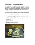
The Portable, Folding, Solar Battery Charging System
USER MANUAL
Model: SLP090F-12S and SLP130F-12S
Dear Customer,
Thank you for purchasing this Solarland product.
Please read the instructions carefully and thoroughly before using.
Index
1. Description of Functions
Page 1
2. Features
Page 1
3. Components
Page 3
4. Specifications
Page 4
5. Installation & Connection
Page 5
6. Display Functions in normal operation
Page 7
7. Trouble-shooting Guide
Page 8
6. Safety Recommendations
Page 9
9. Frequently Asked Questions
Page 10
10. Typical Battery Connections
Page 11
11. Incorrect Battery Connections
Page 12
1. Description of Functions
This Solar Battery Charging Kit is used to charge 12V lead-acid, AGM, or GEL batteries or
battery banks. The system includes the following items:
-Two folding solar panels
-Solar charge controller
-16’ of interconnect cable
-Ring terminal adapter
-Cigar lighter plug adapter
-Cigar lighter socket adapter
-Battery clip adapter
-Anchoring stakes
-Adjustable Support Legs
-Adjustable straps
-Carrying handle
-Padded, metal storage case
The Solarland solar charge controller protects the battery or battery bank from being
overcharged by the PV module. The charging characteristics include bulk, absorbtion, float and
PWM charging stages which Improve the charging efficiency of the system.
The Solarland Solar Battery Charging Systems are perfect for charging and maintaining 12V
battery systems in the following vehicles and devices:
-RV’s
-Boats and Marine
-Trailers (horse and travel)
-Cabins and Cottages
-Construction and farm equipment
-Material Handling equipment
-Camping
-Automotive
-Aircraft
-ATV and Snowmobile
-Motorcycle
-Disaster Preparedness
The Solarland Solar Battery Charging System is intended for use with almost any 12V battery
system.
2. Features
The Carrying Case
The Carrying Case is manufactured from high grade aluminum with
the inside finished with durable, padded foam providing excellent
protection against damage to the solar panels during transportation
and storage. Reinforced corner and gusset protectors are added
where they are most needed.
The Carrying Handle and Tamper Proof Fasteners
The heavy duty Carrying Handle is fitted to the Portable Solar Battery
Charging System using tamper-proof hardware. This configuration
provides the user with a comfortable way to carry the system and, at
the same time, a secure point to affix a security lock and cable (sold
separately).
1
Integrated Smart Solar Charge Controller with LED
Indication
The Solar Charge Controller is mounted behind the solar panels. The
Controller ensures that the battery charging is done safely and
correctly and without damage to the Solar System or the Battery Bank.
The Charge Controller employs a three stage PWM type charging
profile for optimal battery charging. A switch on the controller enables
the user to select between Lead-acid type batteries or GEL type. And, a protection circuit prevents
damage to the controller if the battery leads are accidentally connected incorrectly.
The Portable Solar Battery Charging System is completely automatic and designed to be
connected to the battery bank indefinitely.
Fold Away Adjustable Support Legs
A unique folding system of tilt legs are easy to open, close and adjust
by simply moving the belts and brackets behind the solar panels. This
keeps the solar panels at any desired tilt angle without slipping. By
adjusting the angle of the solar panels throughout the day, maximum
sun exposure is achieved yielding maximum power output and faster
battery charging.
Connecting Cables
The Portable Folding Solar Battery Charging System comes complete
with a 16’ cable that extends from the controller. The cable features an
in-line fuse and a two pin moulded connector enabling any one of four
battery connection adapters to be quickly added. The battery
connection adapters are as follows:
-Ring Terminal Adapter. This adapter attaches permanently to your
battery or battery bank and remains in place at all times, even when the Solar Panel System is not
in use. It is ideal for a battery that is inconveniently located or where the battery terminals are not
easily reached.
-Battery Clips. Use this adapter when temporary attachment to the battery bank is desired.
-Cigar Lighter Plug. Use this adapter when you wish to charge the battery using a cigar lighter
socket that might already be installed in the vehicle. This method can work well provided the cigar
lighter socket is ‘hot’ all all times and that the socket’s circuit is fused at 10 amps or higher.
-Cigar lighter socket. Use this adapter to charge a battery powered device where the device to be
charged is already equipped with a cigar lighter plug. It is important to point out that this will not
work with all devices. For example, some devices such as cell phones or laptop computers have
electronic circuitry between the device and the cigar lighter plug. This circuitry can sometimes
prevent the Solar Charge Controller from activating. If you have further questions about the use
of this adapter, or if you need further assistance, contact your nearest dealer.
2
3. Components
3
2
1
7
4
5
10
8
9
6
11
Number
1
Description
SLP090F-12S
SLP130F-12S
Folding 2 x 45w multi-crystalline
silicon solar panels
Folding 2 x 65w multi-crystalline
silicon solar panels
Qty
1set
2
Automatic smart solar change controller
1pc
3
Rubber Corner Protector
8pcs
4
Heave duty anodized aluminium folding support leg
2pcs
5
Adjustable belt for support legs
2pcs
6
Tent stake
2pcs
7
Heavy duty ABS handle
1pc
8
16’ cable with heavy duty male/female moulded connectors, polarity
keyed, plug/socket, fuse and fuse holder provided.
1pc
9
Battery wire with ring terminals
1pc
10
Battery wire with clamps
1pc
11
Car cigarette lighter plug/socket
1set
3
4. Specifications
Solar Panel
Type
Rated Power (Pm)
90W Multi-Crystalline
silicon solar cell
130W Multi-Crystalline
silicon solar cell
90W (2 x 45W panels in series) 130W (2 x 65W panels in series)
Operating Voltage (Vmp)
17.2V
17.2V
Operating Current (Imp)
5.23A
7.56A
Open Circuit Voltage (Voc)
21.6V
21.6V
Short Circuit Current (Isc)
5.75A
8.31A
±5%
±5%
-40°C~+85°C
-40°C~+85°C
Power Tolerance
Operating Temperature
Standard Test Conditions
Irradiance (E) -1000W/M2, AM 1.5 Spectrum,
Panel Temp.(Tc) =25°C
Solar Charge Controller
Type
12V/7A PWM Controller
12V/10A PWM Controller
Nominal Voltage
12V
13.8V(25°C)
Float Voltage
14.4V
Max. Charge Voltage
13.7V
Charge Restart
Max. Solar Panel Current
7A
Max. Load Current
7A
10A
10A
Self Consumption
<10mA
In-line Fuse
Type
Rated
Standard Glass Automotive
10A/32V
15A/32V
Recomended Batteries (not included)
Model
SLP090F-12S
SLP0130F-12S
Type
12V (60Ah~100Ah)
Lead-acid, GEL, or AGM type
12V (90Ah~150Ah)
Lead-acid, GEL, or AGM type
Dimensions
SLP090F-12S
SLP0130F-12S
Individual Solar Panel
670mm x 530mm x 40mm
26.38” x 20.86” x 1.57”
1010mm x 510mm x 40mm
39.76” x 20.08” x 1.57”
With Panels Folded
670mm x 530mm x 80mm
26.38” x 20.86” x 3.14”
1010mm x 510mm x 80mm
39.76” x 20.08” x 3.14”
With Panels Open
670mm x 1065mm x 40mm
26.38” x 41.92” x 1.57”
1010mm x 1045mm x 40mm
39.76” x 41.14” x 1.57”
Model
4
5. Installation & Connection
STEP 1: Location
Identify the best location for maximum sun exposure. The location should be free of obvious
hazards such as camp fires, rising water, high traffic areas. The front of the Portable Solar Panel
System should face generally ‘South’, located in full sun, all day, with little or no shade between
the hours of 9:00am and 3:00pm. During the summer months in North America, the number of
sun hours may be much longer permitting more energy production. A 25’ extension cord
accessory is available for purchase from Solarland if needed.
STEP 2: Set-up (No Tools Required)
A. Remove the Portable Solar System from
the metal carrying case.
B. Open the folding solar panels after
unlocking the two halves. Fold out the
support legs.
A B
C. Adjust the tilt legs to set the desired angle
C D
of the solar panel. Maximum power
generation occurs when the sun is
1
perpendicular to the face of the solar panel.
2
The ideal angle, for a fixed solar panel, is
3
determined by the seasonal time of year,
and your latitude. In general terms you
subtract 15 degrees from your latitude during summer, or add 15 degrees to your latitude during
winter. The angle can be measured using a common inclinometer available at most home
center stores. Another method to determine the angle is to tilt the solar panel, up and down,
and observe the shadow it casts behind it. Lock the tilt legs in place when the ‘tallest’ shadow is
observed. This ideal time to make this adjustment is at 12:00 noon.
D. Adjust the azimuth of the solar panel. In other words, the direction that the face of the solar
panel points. In general terms, the solar panel should face directly ‘South’. South can be
determined using a simple compass. Another way to adjust the azimuth is to observe the
shadow that the solar panel casts behind it. The edges of the shadow should align perfectly
with the edges of solar panel. The ideal time to make this adjustment is at 12:00 noon.
E. After making both the Tilt and Azimuth adjustments described in C and D above, re-adjustment
Is not required during the day. However, if you like to experiment, and take in interest in solar
energy production, you can increase your overall energy production by as much as 30% per day
by making Tilt and Azimuth adjustments about every two hours using the shadow method
described. Don’t worry about making a mistake. Just have fun.
STEP 3: Connect Panels
On the back of the solar panel, you will observe that the panel on the
left is already connected to the charge controller. Connect the panel
on the right to the
the charge controller using the provided cable and connectors. This
need only be done the first time you use your new Solar System. This
connection can remain in place permanently here after.
5
STEP 4: Connect to the Battery or Battery Bank
A. Be sure the charge controller is set to the correct battery type. Do this by selecting either
Lead-acid’ or ‘Gel’ using the switch on the back. For acid flooded wet cell batteries use the
‘ Lead-acid’ setting. For sealed Gel batteries use the ‘GEL’ setting. For sealed Absorbed Glass
Mat (AGM) batteries, use the ‘Lead-acid’ setting.
B. Unfurl the 16’ cord and attach the appropriate battery connection adapter. The ideal use of
each type is described earlier. Note the location of the in-line fuse.
C. When using the Battery Clips or the Ring Terminal Adapter, make the connections directly to
the battery terminals. IMPORTANT: OBSERVE POLARITY. This means you must be careful to
attach the red wire to ‘Positive’ or ‘+’, and the black wire the ‘Negative’ or ‘-’. If polarity is reversed
accidentally, no permanent damage will occur, but the in-line fuse will blow. In this case, correct
the polarity and replace the fuse.
D. It is generally considered ‘good practice’ to remove the batteries from the vehicle when
charging. This is because dangerous Hydrogen gas, given off by many types of batteries while
being charged, can build up inside confined spaces which could explode under certain
conditions. However, removal of the battery from the vehicle is not necessary provided the
battery is being charged in a well ventilated area. A well ventilated compartment, or a battery
bank tray that has good ventilation to the outside air, is adequate for charging the battery while
installed.
E. When connecting to a multi-battery system or ‘battery bank’, see section 10 for specific details.
F. It is best to attach the Portable Solar Panel System to the battery or battery bank at the
beginning of each camping event rather than to wait until the battery is dead before connecting.
This allows the Solar Panel System to ‘keep-up’ with the loads on the battery and fully charge it
each day. This leads to longer overall battery life and better electrical system operation.
Battery Clamp
Ring Terminals
The battery wire is first connected to battery.
There will be no power output from the Charge Controller until the unit is
connected to the battery.
When the Portable Solar Panel System is first connected to a battery or battery bank, and the
panels are exposed to full sun, the charge controller undertakes a self-check and configuration
routine. In some cases this may take up to 3 minutes during which the LED’s on the charge
controller will not be illuminated and the battery will not be receiving any charge. Once the
configuration and self-check procedure is complete, the system will engage, the charging process
will commence, and the Yellow LED will illuminate.
6
6. Display Functions in Normal Operation
The Charge Controller is equipped with 2 LED’s to indicate the battery State-of-Charge it is
currently in.
-Yellow = System charging. Current is flowing to the
battery or battery bank. Peak battery voltage may be
observed between 13.9 and 14.4 indicating the battery
is fully charged (temperature dependent).This condition
will continue for approx. 2 hours before the ‘float’ mode
engages.
Yellow LED
Green LED
-Green = Battery full. The Charge Controller has entered the ‘float’ mode. Current is still flowing
to the battery or battery bank. But, the voltage has been reduced for maintenance charging.
Battery voltage in this mode may be observed around 13.8V but could be slightly different
depending on temperature.
7
7. Trouble-shooting Guide
Please Note:
Your new Portable Solar System is maintenance free. There are no user-serviceable parts in this
unit. If you have any problems, please contact your dealer immediately. If the controller becomes
submerged, remove the connection to the battery, and shake as much water out of the controller
as possible. Leave the solar panel system face down in direct sun, with the controller directly in
the sun, for two full days. Next, check the in-line fuse, and then attempt to restore operation by
reconnecting to the battery. If the yellow light on the charge controller does not illuminate,
contact your Solarland dealer immediately for assistance.
The ‘CHARGING’ LED does not glow yellow.
-Ensure the solar panels are exposed to sunlight.
-Ensure all solar panel cables are connected correctly and free from damage.
-Ensure the 16’ cable between the Solar Controller and the battery is connected correctly and free
from damage.
-Check the battery voltage. If the voltage is less than 8V DC, the Solar Controller will not turn on.
-Be sure the polarity is correct. When using the Battery Clips or the Ring Terminal Adapter, be
sure the Red lead or Positive (+) is connected to the Positive post (+) on the battery. Then be
sure the Black lead or Negative (-) is connected to the Negative post (-) on the battery.
-Check the in-line fuse to be sure it is not burnt. If so, replace with a 10A fuse (90 Watt unit) or a
15A (130 Watt unit). If fuses continue to burn, the cause is either reversed polarity at the battery
terminals, or some other catastrophic charge controller failure. However, we have found that
almost all blown fuses to be the result of polarity errors.
The ‘FULL’ LED doesn’t glow Green.
-The battery is not fully charged. In certain circumstances where the battery or battery bank is
under constant load, the fully charged state may never be reached long enough for the ‘float’
mode to be engaged. This is common and normal in most RV and Marine applications.
There is no voltage output reading from the panel.
-The Solar Panel System must be connected to the battery or battery bank before the Charge
Controller will engage.
-Battery voltage is too low. Battery is completely dead, shorted, or has otherwise failed. A battery
voltage of 8V DC or higher must be present before the Charge Controller will engage. Replace
the battery.
Battery appears to fully charged with the Portable Solar Panel System connected, but goes dead
quickly.
-Battery has failed. This can happen to old batteries and even new ones if not properly cared for.
Confirm battery condition with a 100 Amp ‘Battery Load Tester’ obtained at any auto parts store
or ask your Solarland dealer to test the battery for you. Replace the battery if necessary.
8
8. Safety Recommendations
1. Read & completely understand this instruction manual before use. Always keep this manual in
a convenient location.
2. To reduce the risk of injury, charge only 12V lead acid batteries, AGM & GEL batteries. Other
types of batteries may be subject to bursting which can lead to personal injury & property
damage. If uncertain about types and/or charging procedures contact the battery
manufacturer 6V batteries wired for 12V operation are permitted.
3. Always use a well-ventilated space. Batteries emit explosive gases. These explosive gases
can be ignited by a spark, cigarette or naked flame such as a cigarette lighter or matches.
4. Make sure the voltage of the battery being connected is the same as the output voltage of the
solar controller.
5. Make sure to connect with correct polarity (positive pole to the positive post, negative pole to t
he negative post).
6. It is generally considered ‘good practice’ to remove the batteries from the vehicle when
charging. This is because dangerous Hydrogen gas, given off by many types of batteries while
they are being charged, can build up inside confined spaces which could explode under certain
conditions. However, removal of the battery from the vehicle is not necessary provided the
battery is being charged in a well ventilated area. A well ventilated compartment, or a battery
bank tray that has good ventilation to the outside air, is adequate for charging the battery while
installed.
7. Keep away from explosive gases, flames, smoke & sparks.
8. Keep away from any flammable substances.
9. Always adhere to battery manufacture’s recommendation when charging batteries.
10. Given sufficient light, solar panels always generate energy even when they are disconnected.
Accidental ‘shorting’ of the terminals or wiring can result in spark causing personal injury or a
fire hazard.
11. This unit is not intended for use by young children or infirm persons without supervision. Do not
allow unsupervised young children to play with this unit.
12. Always avoid charging an old, damaged, overly discharged, defective battery.
13. When testing or working on or around a battery it is advisable to wear protective eye glasses.
14. Have plenty of fresh water & soap available in case battery acid comes into contact with skin,
eyes or clothing.
15. If the battery acid makes contact with skin or clothing, flush immediately with large amounts of
water. In case of accidental eye contact with battery acid, flush eyes for at least 15 minutes
with clean water. The eyes should be submerged under water & kept open. See a doctor
immediately. Do not use eye drops or other medication unless instructed by a doctor.
16. When working with a lead-acid type battery, be careful not to short-out the battery with a metal
tool or object. Remove all personal items such as watches, rings, bracelets and necklaces.
The possibility of a short circuit exists, which can damage such items & cause severe burns
and/or personal injury.
17. It is important that the battery gets fully charged frequently (at least once per week). Otherwise
the battery can become permanently damaged. Partially charged batteries, especially in hot
weather, can quickly sulfate internally which is an irreversible condition. It is good practice to
prevent a battery from being discharged below 50%. Deeper discharging severely shortens
battery life.
18. Keep the surface of solar panels clean from dust & clean with a soft cloth. Do not walk on
modules.
18. Avoid solar panel contact with water, acid or alkali.
19. Do not scratch or bend solar panels.
20. Do not disassemble or open the solar panels & the solar controller. There are no
user-serviceable parts in this unit.
21. When mounting solar panels on a high location, adhere to all relevant safety regulations.
22. Do not pack heavy items on top the solar panels when storing or transporting.
23. High temperatures will reduce the performance of solar panels, and other solar components,
lowering power output. High quality solar cells, efficient Charge Controllers, proper wiring and
connectors, and good ventilation help mitigate these effects. Operating at cold temperatures
has the opposite, positive effects on your Portable Solar System and helps increase the power
output. Remember: Colder is better.
9
9. Frequently Asked Questions
How does the solar panel work?
The solar panel converts sunlight energy into DC electric power & can be used to charge a
rechargeable battery.
How many solar panels will it take to run my appliances?
As a general rule the user should establish the amps required to run the appliances & multiply
them by the expected module voltage.
Power Calculations:
Amp Hours (Ah) = Current (Amps) x Working Time (Hours)
Module Power (W) = Current (Amps) x Expected module voltage (V)
After completing these calculations the capacity of the solar panels can be established.
Example:
The following table represents a typical portable appliance configuration.
Watts
Voltage
Amps
Hours
Amp Hours
12V Fluorescent Light
8
12
0.67
4
2.6
12V B&W Television
20
12
1.67
1
1.67
12V Radio
5
12
0.42
1
0.45
12V Fan
4
12
0.33
5
1.65
12V Travel Iron
120
12
10
1/6
1.67
12V Fridge
45
12
3.75
6
22.5
Appliance
Estimated Consumption
30.51
Amps Hours: 30.51 Amp Hours per Day
Assumption: Solar panel is exposed to 6 hours of suitable sunlight each day.
The required current from the system would be 30.51 Amp Hours/6 Hours = 5.09 A.
The required watts of the system would be:
5.09A×17.2V÷0.8=110W (17.2V --- Module Vmp, 0.8 --- Power Consumption Factor)
In this example a 110 Watt panel is required to run the appliances for the desired time.
How much battery capacity is required?
Solar power systems are generally sized to give plenty of reserve (autonomy) from the
battery or battery bank.
Battery Capacity Calculation:
Current (Amps) x Hours = Amp Hours (Ah).
In the example above we have determined we required 30.51 Ah per day.
It is not good to run a battery all the way down to zero during each charge cycle as it severely
shortens the battery life. It is good practice to leave at least 50% charge in the battery. For
the example above, we need at least 30.51 Ah / 0.7 = 43.6 Ah. (0.7 or 30% is added in to the
equation to account for losses due to resistance and other system inefficiencies). If a typical
100 Ah, deep cycle, RV/Marine battery is used, this equates to about 43.6% depletion daily
and is adequate in this example.
10
10. Typical Battery Connections
CORRECT
Load
CORRECT
Load
CORRECT
Load
12V
6V
12V
6V
12V
Chassis
Ground
To
Accessory
Loads
Typical Series/Parallel
RV Installation
Fuse
CORRECT
6V
6V
6V
To
Inverter/
Charger
Typical Series/Parallel
RV Installation
CORRECT
To
Accessory
Loads
Fuse
6V
Shunt
Shunt
To
Inverter/
Charger
6V
6V
6V
6V
11
11. Incorrect Battery Connections
Typical Series/Parallel
RV Installation
To
Accessory
Loads
Fuse
INCORRECT
6V
6V
6V
6V
Typical Series/Parallel
RV Installation
INCORRECT
Shunt
To
Inverter/
Charger
To
Accessory
Loads
Fuse
Shunt
To
Inverter/
Charger
6V
6V
6V
6V
Chassis Ground
Liability Exclusion
The manufacturer shall not be liable for damage, especially on the battery, caused by use other
than as intended or as mentioned in this manual or if the recommendations of the battery
manufacturer are neglected. The manufacturer shall not be liable if there has been service or
repair carried out by any unauthorized person.
Subject to change without notice
Vertion:20111101
www.solarland.com
12
SOLARLAND
B11 Huayou Dong Rd.,
Huayou Industrial Area,
National High-tech Industrial Area,
Wuxi, 214028
Jiangsu, P.R.China
Tel: +86 510 82261100
Fax: +86 510 85203812
www.solarland.com
[email protected]
Chicago Office: PO BOX 6128,
Lindenhurst, IL 60046, USA
Tel : 847-282-4796
Cell: 847-274-8736
Fax: 847-245-8649
E-mail: [email protected]